Abstract
Deformation detection determines the quantified change of a scene’s geometric state, which is of great importance for the mitigation of hazards and property loss from earth observation. Terrestrial laser scanning (TLS) provides an efficient and flexible solution to rapidly capture high precision three-dimensional (3D) point clouds of hillside areas. Most existing methods apply multi-temporal TLS surveys to detect deformations depending on a variety of ground control points (GCPs). However, on the one hand, the deployment of various GCPs is time-consuming and labor-intensive, particularly for difficult terrain areas. On the other hand, in most cases, TLS stations do not form a closed loop, such that cumulative errors cannot be corrected effectively by the existing methods. To overcome these drawbacks, this paper proposes a deformation detection method with limited GCPs based on a novel registration algorithm that accurately registers TLS stations to the UAV (Unmanned Aerial Vehicle) dense image points. First, the proposed method extracts patch primitives from smoothed hillside points, and adjacent TLS scans are pairwise registered by comparing the geometric and topological information of or between patches. Second, a new multi-station adjustment algorithm is proposed, which makes full use of locally closed loops to reach the global optimal registration. Finally, digital elevation models (DEMs, a DEM is a numerical representation of the terrain surface, formed by height points to represent the topography), slope and aspect maps, and vertical sections are generated from multi-temporal TLS surveys to detect and analyze the deformations. Comprehensive experiments demonstrate that the proposed deformation detection method obtains good performance for the hillside areas with limited (few) GCPs.
1. Introduction
Deformation detection has been defined as the surveying of a region in different epochs and the identification of geometric differences based on the captured data [1]. Its purpose is to determine if the geometric state of the area of interest has changed as well as the quantified change. The detection of the deformations of hillside areas has been an active and important task in mitigating hazards and property loss in the field of earth observation. The continuous occurrence of hazard events increased the demand for new techniques for further measurement and analysis. From the past to the present, traditional surveying techniques (e.g., static GPS, Real-time kinematic: RTK, total station survey) and remote sensing based techniques, such as close-range photogrammetry, unmanned aviation vehicles (UAVs), and laser scanning, are widely used to capture the spatial data of hillside areas by integrating them with one another or applying them individually. TLS is gaining attention due to the high point density and spatial resolution data that can be acquired in a short time. Its application in unstable hillside areas may provide important information for achieving a more complete knowledge of the active processes that could forecast potential geo-disasters [2].
In the literature of deformation detection based on laser scanning points or dense photogrammetric image points, both the registration and deformation detection techniques have been covered from different angles. Therefore, these two aspects are reviewed in the following two sub-sections.
1.1. Registration Techniques of Point Clouds
The registration technique of 3D points has been applied in various applications (e.g., mobile robotics, object recognition, and 3D reconstruction). The registration methods have been widely classified into two categories: Coarse and fine registration. The coarse registration provides initial values for fine registration to avoid falling into the local minimum. The widely used coarse registration methods include: Point signature [3], spin image [4], shape context [5], fast point feature histograms (FPFH) [6], normal vectors/principal curvature/curvature change [7,8,9], geometric primitives [10,11,12], etc. The most popular fine registration method is the ICP algorithm [13,14] and its variants [15,16,17,18]. ICP is the iterative closest point algorithm. It optimizes the transformation between two point clouds, by minimizing the square errors between correspondences. Furthermore, there are also many other recent methods, including 4PCS (4-points Congruent Sets) [19], SLAM (Simultaneous Localization and Mapping) [20], probabilistic registration [21], genetic algorithm [22], etc.
Both coarse and fine registration algorithms can be further categorized into pairwise registration and multi-station registration methods. Pairwise registration determines the transformation between two adjacent point clouds while the multi-station registration takes multiple point clouds into account to correct the cumulative errors introduced by pairwise registration. Most of the above methods belong to pairwise registration. More recently, Tombari et al. proposed a 3D descriptor that encodes histograms of the normal vectors of points within a support, describing the local reference frame of a feature point [23]. Similarly, Guo et al. constructed a unique local reference frame and applied rotational projection statistics to describe it [24]. Contrastingly, Geng et al. defined a new function to measure feature similarity by calculating the distance function based on the neighborhood constraints of geometrical features [25].
The above pairwise registration methods have demonstrated their superior performance for two adjacent point clouds. However, they are ineffective for multiple stations since cumulative errors are not considered adequately. To address this issue, various multi-station registration methods have been proposed. Williams et al. applied a weighted matrix encoding the correspondence information to calculate the optimal transformation iteratively [26]. Huber et al. constructed a connected sub-graph to order the procedures of operation to reduce the cumulative errors [27]. Similarly, Zhu et al. sequentially registered each station to a model constructed by other stations [28]. Their transformations are sequentially refined by traversing all stations. Guo et al. proposed a weighted motion method to provide more reliable pairwise registration results, improving the accuracy of multi-station registration [29]. Moreover, the multi-station adjustment algorithm is another efficient method to correct cumulative errors. However, the existing multi-station adjustment methods mainly solve this problem based on a global closed loop constructed by multiple stations [30,31,32].
For mountainous areas, the existing pairwise registration methods do not work well for the following reasons: (1) Registration primitives encoding distinctive information are difficult to select; (2) the similarity of different points’ local information affects the determination of correspondences. Besides, in practice, it is difficult for TLS stations to form an efficient closed loop. The application of existing multi-station adjustment methods leads to compromised results that restrict their applications (e.g., deformation detection). Therefore, it is necessary that an efficient registration algorithm is developed.
1.2. Deformation Detection Methods
Various remote sensing techniques have been applied in the field of deformation detection. Passive space-borne imaging based solutions can collect optical images with a centimeter ground resolution. Then, traditional photogrammetry based data processing pipelines are adopted to generate ortho-images, DSMs (digital surface models), and DTMs (digital terrain models) for further deformation measurement. Compared with passive space-borne imaging based solutions, airborne based and terrestrial laser scanning provide a direct way to rapidly capture high density 3D surface coordinates, which can be processed using filtering operations, such as a slope-based filter (e.g., Vosselman, [33]), to separate ground points and non-ground points for DTM generation. Although photogrammetric DTMs generated from passive space-borne images are not usually as accurate and precise as LiDAR-based (Light Detection and Ranging) DTMs [34], they can still achieve a centimeter accuracy that meets the requirements of various applications [35].
Generally, traditional airborne- and satellite-based remote sensing techniques, such as differential InSAR (Interferometric Synthetic Aperture Radar), are suitable for the detection of deformations over large areas (e.g., multiple square kilometers, [36,37,38]). On the one hand, since each scene image of InSAR has wide coverage, the average cost of a large area is low. However, if used for a small specific area, the cost is relatively high. On the other hand, the temporal resolution (collection frequency) of InSAR data may affect its application of deformation detection. Because many InSAR datasets have a long or fixed revisit time, if fast-changing or large deformations occurred during the acquisition period, the problem of decorrelation may be caused [39,40,41,42].
The use of radio controlled mini-UAVs to collect the data of small specific areas is convenient, flexible, and cheap. In the last five years, they have been widely used to collect high geometric and temporal resolution data (e.g., images and point clouds) with a consumer grade optical camera or a light weight laser scanner (e.g., Velodyne VLP-16, 0.83 kg; RIEGL VUX-1LR, 3.5 kg). Thus, the use of mini-UAVs for the detection of deformations in mountainous areas is possible and cost affordable. Related researches have been published [43,44,45,46]. However, mini-UAVs apply a top-down acquisition method to collect data, making it difficult to collect the data from some steep areas. Although an oblique camera can be mounted on mini-UAVs, it generally has a lower accuracy since more parameters will be introduced in the photogrammetric procedures [47].
Plus, TLS can provide huge amounts of measurements in a short time. It enables flexible collection of dense 3D points in areas of interest, generating a more detailed description of the slope topography, thus improving our understanding of deformations in hillside areas. Most existing methods set up various retro-reflective targets (GCPs) in the environment to ensure geo-referencing and the alignment of different views’ stations [48,49,50]. However, the GCPs should be deployed in each TLS survey. The deployment is generally time-consuming and labor-intensive, and is sometimes very difficult when dealing with steep terrain. Few studies have investigated the detection of deformations using limited GCPs based on TLS points.
Overall, this paper utilizes the UAV dense image points as a reference frame work to register multi-temporal TLS surveys automatically and accurately. By reducing the GCPs of each TLS survey, more efficient and economic deformation measurements of slope topography are obtained. The main contributions of the proposed method are as follows:
- (1)
- We propose an efficient pairwise registration algorithm based on patch primitives to register adjacent point clouds of hillside areas coarsely. The main feature of the method is that the information of the trend and topographic undulation of the mountains together with multi-scale information of each patch are applied to determine the correspondences robustly.
- (2)
- We propose a novel multi-station adjustment algorithm to accurately register TLS and UAV dense image points, which corrects the cumulative errors based on locally closed loops formed by adjacent stations. The introduction of virtual points makes the linearization of the condition equation group possible, reaching the global optimal alignment of all TLS stations.
- (3)
- Based on the registration techniques, we generate DEMs, slope and aspect maps, and vertical sections of multi-temporal TLS surveys for deformation detection and terrain morphological analysis, thus demonstrating the effectiveness of the high resolution deformation detection method with limited GCPs.
The rest of this paper is structured as follows. Following this introduction, Section 2.1 and Section 2.2 describe the study area and data acquisition. Section 2.4 and Section 2.6 give a detailed description of the proposed pairwise registration and multi-station adjustment method. Then, the registration algorithms and deformation detection results are validated and discussed in Section 3 and Section 4. Finally, the conclusions and future research directions are presented in Section 5.
2. Materials and Methods
2.1. Experimental Area
The experimental area is located in a mountainous area near the East Sea, China (Figure 1). The area covers about 0.15 km2 and is distributed along the coastal zones with elevations ranging from 9.1 m to 109.0 m. The slope facing the East Sea is steep and harsh, and the top topography is relatively flat. A quad-rotor helicopter md4-1000 (Microdrones GmbH, Siegen, Germany) equipped with a digital camera consisting of an affordable remote sensing platform was adopted to collect the optical images over the study area. Besides, we set up TLS (Leica C10) near the coastal zones to collect 3D laser scanning points. The parameter descriptions of md4-1000, the digital camera, and the laser scanner are listed in Table 1. Based on the data of the flat areas (both UAV and TLS collect well), this paper takes the geo-referenced UAV image points as the framework, and registers multi-temporal TLS surveys to the UAV image points.
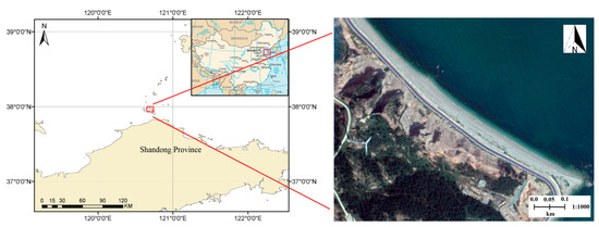
Figure 1.
The location of the study area and satellite image (The satellite is worldview-2; 8-band multispectral sensor was used; acquisition date: 19 September 2017).

Table 1.
Parameters for the md4-1000, digital camera, and Leica C10.
2.2. Data Acquisition: UAV Flying and Terrestrial Laser Scanning
We collected the optical images with a md4-1000 UAV equipped with SONY ILCE-7R. The geo-referenced UAV image points were used as the framework to align multi-temporal TLS surveys. The UAV flight was performed in September 2014, and the flight task was executed with a predefined flying routine (four strips) by a remote controlled computer (shown in Figure 2). The flight elevation was about 150 m with a ground resolution of 1.6 cm and the flight range was up to 20 minutes. The wind scale was less than force-3. Longitudinal overlap was over 70% and side overlap was over 55%. To attain a smaller image blur and better illumination, the shutter speed of the camera was set to 1/1000 s. Seven GCPs (two for check points) were set up to geo-reference the UAV dense image points accurately. These conditions together ensured the quality of the UAV image points (plane accuracy 3.2 cm, elevation accuracy 4.6 cm). Five periods of TLS surveys were performed from March 2013 to January 2015. The TLS (Leica C10) was set up near the coastal zone to capture the 3D point clouds of slope areas with an average point span of 0.08 m. For each survey, the TLS captures data with several scans, ranging from 3 to 6 stations.
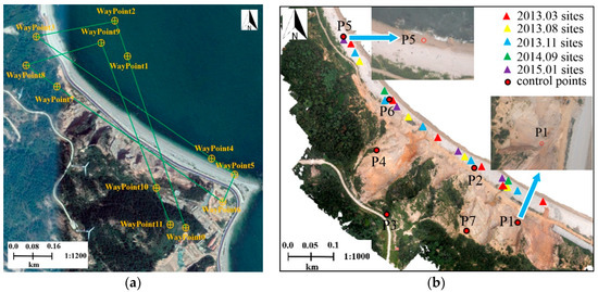
Figure 2.
UAV flight routine, and TLS sites and GCPs distribution: (a) UAV flight routine (WayPoint0 is the take-off position, WayPoint11 the is landing position); (b) TLS sites of different surveys and GCPs distribution on the dense 3D image points (P1–P7 are the positions of GCPs, P6 and P7 are selected as the check points).
Three main procedures were scheduled to ensure the quality of DEM (plane and elevation accuracy were less than 5.0 cm) generated using the drone-acquired data: (1) Designing the flight plan, referring to the desired flight height, ground sampling distance, and image overlap; (2) selecting the location of GCPs (well-distributed in bare-land, no-change area) based on geospatial data; and (3) placing and measuring GCPs on site. Seven GCPs were surveyed by GPS-RTK, the horizontal and vertical accuracy was expected to be within 0.10 m and 0.15 m, respectively.
2.3. Method Workflow
Two independent pipelines were deployed to process TLS point clouds and optical images before accurately registering TLS data to the UAV dense image points. The proposed method encompasses three key components: Patch based pairwise registration of TLS stations, multi-station adjustment of TLS and UAV points, and terrain deformation analysis. The workflow for the detection of deformation with the UAV and TLS data is shown in Figure 3.
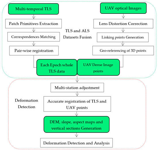
Figure 3.
Workflow for the detection of deformation with UAV and TLS data.
2.4. Pairwise Registration between TLS Stations
2.4.1. Patch Primitive Extraction and Multi-Scale Descriptor Construction
For a chaotic mountainous environment, mismatched correspondences are easily introduced since many points’ local geometric information at a single (predefined) scale is similar. Apart from the local geometric information, the trend and topographic undulation of mountains is also important information. To make full use of the information, we proposed the extraction of patch primitives to register mountainous data robustly. To ensure the completeness and consistency of patches, the operation of 3D smoothing is necessary. A 3D Gaussian kernel [51] was applied to smooth the 3D point clouds, written as:
where di denotes the distance from a given point to its neighborhood point, pi, and is the mean square root error. The larger is, the larger the smoothing region should be, and larger size features will be smoothed. Then, 3D point clouds were convolved with Gaussian kernel to realize the 3D smoothing. Based on the smoothed point clouds, the method below was used to extract patch primitives.
Select a seed point randomly, and take a fixed length as the clustering radius. The clustering radius is determined with respect to the median scene size of the stations, which is determined by the bounding box of each point cloud. Cluster points according to the normal vector of each point. The normal vector of each point is estimated by the principal components analysis (PCA) algorithm and the directions of normal vectors are unified by the consistent propagation algorithm. For each cluster obtained in the previous iteration, select the point with the largest curvature change, Mc, as the new seed point. The value of curvature change is calculated by the normal vectors of neighborhood points, as shown in Formula (2). Based on the new seed point, cluster again to get new clustered points. Repeat the above procedures until the clustered points are unchanged from the points of last iteration. For each patch, select the newest seed point as the feature point of this patch, and calculate the average normal vector as its normal vector. Figure 4 illustrates the curvature change rendering of two adjacent stations after smoothing. It demonstrates that the overlap areas have similar geometric information, suggesting that 3D smoothing ensures the consistency of patches from adjacent stations.
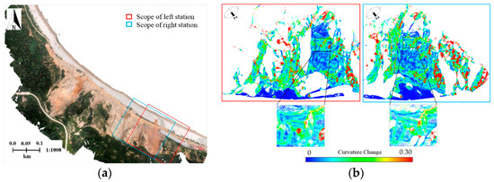
Figure 4.
Curvature change rendering of adjacent stations after smoothing: (a) Scopes of left and right stations; (b) curvature change rendering of 3D points from the left and right station (color ramp represents different values of curvature change).
Note that mountainous features have multi-level details, and this multi-scale information of different features has significant differences that can be used to accurately distinguish them. To describe this multi-scale information of a feature, multiple feature responses (e.g., the curvature, curvature change, or other geometric information) are calculated across a set of discrete scales. In this paper, for each patch, we calculated the curvature change values of its feature point within various neighborhood ranges to comprehensively describe its multi-scale information.
The specific steps are as follows: According to the corresponding relationship between the original points and the smoothed points, find the original points corresponding to each feature point of patches. Then, for each corresponding point, search the original points within various neighborhood ranges (e.g., the neighborhood radii of four scales are set as: 1.0 m, 1.5 m, 2.0 m, and 2.5 m, respectively) to calculate its curvature changes, forming the multi-scale descriptor of each patch.
2.4.2. Matching Strategy and Transformation
To improve the correct matching rate of patches, we applied the triple matching strategy. The detailed procedures are as follows:
- Step 1:
- Select three non-colinear patches from the left and right station, respectively. For each station, calculate the mixed product of the normal vectors of patches, and calculate three distances between them.
- Step 2:
- Judge whether the angles between the patches of the left station are identical with that of the right station by comparing their mixed products. If not, repeat Step 1.
- Step 3:
- Compare the multi-scale information of each patch feature point from two stations for equality. For each scale, the difference threshold is determined by the mean square error of all points within the patch. If three pairs of similar points cannot be obtained, repeat Step 1.
- Step 4:
- Compare the corresponding distances of two stations for equality. If three correspondences are obtained, repeat the above steps until enough matched points are obtained.
The pseudo-code of tripe matching strategy is listed on the next page.
We calculated the rotation and translation parameters separately to obtain the transformation parameters robustly. After the above matching, any four non-collinear pairs of feature points from patches are selected to form two lines. Inspired by the method of [52], the transformation parameters were calculated as follows. Let be the vectors of two lines from the left station. Then, we have:
where indicates a dot product, Cartesian coordinate frame, . Similarly, can be derived from the right station. The rotation matrix is:
Further, the voting principle was used to determine the final rotation parameters. Then, we calculated the translation parameters by the distance differences between the perpendicular midpoints of two pairs of lines (midpoints are unique and easily obtained). Then, the translation parameters were optimized with the voting principle again. Finally, the transformation parameters were obtained as the initial values for fine registration (multi-station adjustment).
| Algorithm Matching of triple patches |
| 1. lPts and rPts are feature point array of triple patches selected randomly |
| 2. lMixedP = (lPts[0].normal, lPts[1].normal, lPts[2].normal); |
| 3. rMixedP = (rPts[0].normal, rPts[1].normal, rPts[2].normal); |
| 4. //lPts[i].normal, rPts[j].normal are the normal vectors of corresponding patch, i∈[0,3], j∈[0,3] |
| 5. // lMixedP and rMixedP are the mixed products of normal vectors of triple patches. |
| 6. if | lMixedP- rMixedP | > Threshold then |
| 7. return |
| 8. end if |
| 9. //Match patches by the multi-scale informaiton of feature points |
| 10. for i from 0 to lPts.size()-1 |
| 11. for j from 0 to rPts.size()-1 |
| 12. if isimilar(lPts[i].multiscales, rPts[j].multiscales ) = = true then |
| 13. onePair.left = i; onePair.right = j; PairArray.push_back(onePair); |
| 14. break |
| 15. end if |
| 16. end for |
| 17. end for |
| 18. if PairArray.size() != 3 then |
| 19. return |
| 20. end if |
| 21. //Match patches by the distances between feature points |
| 22. flag = 0 |
| 23. for i from 0 to 2 |
| 24. for j from i+1 to 2 |
| 25. if distance(lPts[PairArray[i].left], lPts[PairArray[j].left]) = = |
| 26. distance(rPts[PairArray[i].right], rPts[PairArray[j].right]) |
| 27. then flag++ |
| 28. end if |
| 29. end for |
| 30. end for |
| 31. if flag != 3 then |
| 32. PairArray.erase(); //PairArray is the array of corresponding points |
| 33. end if |
2.5. Dense Image Points Generation from UAV Optical Images
Compared with traditional aerial photogrammetric surveying, UAV provides a flexible and cost-effective solution for capturing high spatial resolution images, however, the images may have orientation changes and distortions because of possible trembling of the light weight UAV. The 3D data generated from the images, if characterized by a proper accuracy and resolution, can be considered a faithful numerical description of the slope topography [53], which can be helpful to evaluate the deformations of the slope.
First, the blurred images were discarded, and the lens distortions of the captured images were corrected. Starting from at least two images with known EO (EO refers to the exterior orientation, it describes the position and orientation of the camera when the image is taken with six parameters: Projection center coordinates and the rotations around axes), image matching techniques were applied to generate linking points, whose spatial intersection gives general 3D coordinates in the control points’ coordinate system. The resulting set of 3D points constitutes the so-called point cloud. The remaining images were imported into the Pix4D software [54] for aerial triangulation adjustment (construction of free network) and multi-view stereo technology to obtain dense image points. Then, the GCPs were used to geo-reference the dense image points to the control points’ coordinate system. After processing, the check points show that the achieved dense image points were convincing (plane accuracy 3.2 cm, elevation accuracy 4.6 cm).
The TLS scans were pairwise registered considering Section 2.4. Then, the coarse registered TLS scans were accurately aligned with the dense image points by the multi-station adjustment algorithm in the next section.
2.6. Multi-Station Adjustment Based on a Locally Closed Loop
The registration of multi-temporal TLS surveys to the UAV dense image points can transform them into a uniform spatial reference framework. Particularly, using the UAV dense image points as the reference framework will also reduce the GCPs of the filed survey. Patch based pairwise registration in Section 2.4 was applied to provide initial values between the UAV dense image points and the pairwise registered TLS point clouds. Few patch primitives were extracted from motion-changed regions (e.g., collapse areas), ensuring the robustness of the patch based coarse registration.
On the other hand, cumulative errors were introduced since TLS point clouds were pairwise registered. TLS stations and UAV dense image points do not form an effective closed loop, such that traditional multi-station adjustment methods cannot be used to correct the errors. To register the TLS and UAV data of a hillside area accurately, we constructed a condition equation group that can be conveniently linearized for multi-station adjustment based on locally closed loops formed by adjacent stations.
Three-fold, or upwards of three-fold, overlap usually exists between TLS stations and UAV data. Taking three-fold overlap, for example, to minimize the cumulative errors, multi-station adjustment should be conducted under the constraints of the correspondences from three overlap regions. Suppose three stations are: T1, T2, and T3 (T1 is fixed), respectively. Provided by the initial values, the nearest neighbor search algorithm is used to obtain the corresponding points from each overlap region. Suppose and are the corresponding points of T1 and T2, and and are the corresponding points of T2 and T3, respectively. According to the correspondences, condition equations can be formulated:
Here, R12 and T12 are the transformation parameters between T1 and T2, and R23 and T23 are the transformation parameters between T2 and T3. According to the theory of vision, Formula (5) can be linearized. For instance, the linearized error equation of T1 and T2 can be written as:
Here, are the initial transformation parameters, , and are the residuals of the initial translation parameters and rotation angles. are the observations and are their corrections to balance Formula 6.
Suppose and are the corresponding points of T1 and T3. However, two sets of transformation parameters between T1 and T3 make it difficult for its condition equation to be linearized. To form new equations that can be linearized, we introduced a virtual point to transform the original condition equation into two condition equations, written as:
Here, is a virtual point in T2 that corresponds to and .
According to Formula (6), we constructed the error equation group as follows:
The matrix expression can be written as:
Here, similar to Formula (6), are the corrections of , and and are the corrections of and , respectively. These corrections are used together to balance Formulas (8) and (9).
Based on the initial values of registration, we calculated the residuals of R12, T12 and R23, T23 iteratively. For upwards of a three-fold overlap, multi-station adjustment can also be operated according to the above method. The locally closed loops are considered sequentially (the adjusted TLS stations are fixed) to optimize each TLS station separately, correcting the cumulative errors, and reaching the global optimal alignment of all TLS stations. Figure 5 shows the registration result of the UAV data and one TLS survey. Edge areas (red circles) demonstrate that good fusion of the TLS stations and UAV data was achieved, reflecting the effectiveness of the registration method.
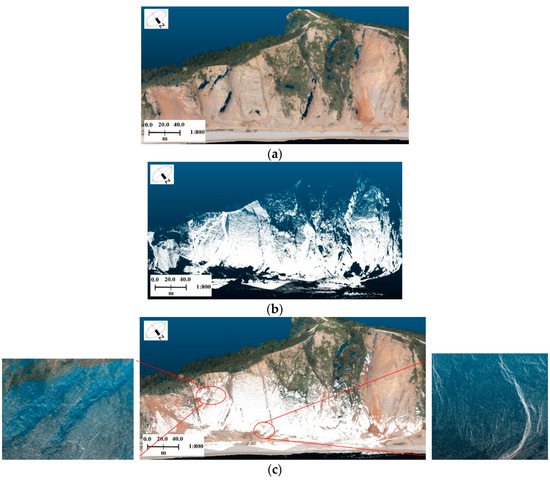
Figure 5.
Multi-station registration result of UAV and TLS data of one survey: (a) UAV dense image points (the color is rendered by RGB from images); (b) pairwise registered TLS stations of one survey; (c) multi-station adjustment result of UAV and TLS data.
2.7. DEM Generation and Deformation Comparison between Observations
DEMs of multi-temporal TLS datasets are usually used to analyze the deformations of areas of interest. To focus on the ground data of a hillside, we applied the progressive triangulated irregular network filtering algorithm [55] to filter the isolated vegetation before the construction of DEMs. The filter threshold varies based on the terrain smoothness, using a coarse-to-fine scheme. Regular grids of DEMs were created since it is the simplest and the most efficient approach in terms of storage and manipulation. The resolution of the generated DEM was 0.2 m (horizontal resolution), providing a detailed description of the scanned area. Since all the surveys were transformed into the control points’ coordinate system, it is feasible to compare the multi-temporal DEMs to measure and analyze the terrain deformations, and analyze the terrain surface of the areas of interest by marker pegs measured previously. The comparison was implemented in ArcGIS 10.5, where the elevation difference of each grid of the two-point clouds was measured to calculate the volumetric deformation of the changed areas.
In deformation detection, the slope and aspect are two vital geomorphic parameters, as they efficiently describe the relief and structure of the terrain surface. The slope of one surface point denotes the degree of the terrain surface inclination at this point, and the aspect represents the direction of the largest elevation change. For a given point on a terrain surface, z = f(x, y), the slope, S, and aspect, A, are defined as the function of the gradients in the X and Y directions (West-East and North-South):
where fx and fy are the gradients at the West-East and North-South directions, respectively. The key step in determining the slope and aspect of one surface point is the calculation of fx and fy. For one grid DEM, fx and fy are obtained by the finite differential of a local moving window (e.g., 7 × 7 window).
3. Results
3.1. Registration Experiments
3.1.1. Extraction of Patch Primitives
According to Section 2.4.1, to ensure the completeness and consistency of the patches extracted, the TLS point clouds were first smoothed by the 3D Gaussian kernel. Then, for the point clouds of each station, patch primitives were extracted, where the clustering radius of patch was set to 2.0 m according to the method mentioned above. The extraction results of six stations are shown in Figure 6. In Figure 6, clusters of points of each color represent one patch primitive (colors were rendered randomly).
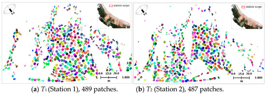
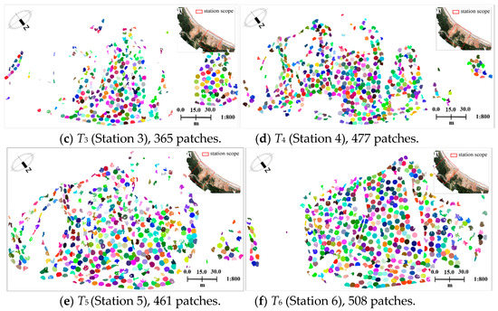
Figure 6.
Patch extraction results of six TLS stations from March 2013.
Figure 6 demonstrates that the trend and topographic undulation of the hillside area is described effectively by numerous patches in different directions. It also illustrates that the iterative patch extraction method ensures the similarity of patches in overlapping regions. The extraction results of six TLS stations suggest that lots of patches were extracted, ensuring a sufficient number of corresponding patches in the overlapping regions.
3.1.2. Accuracy Evaluation of Pairwise Registration and Multi-Station Adjustment
To evaluate the accuracy of the coarse registration (patch based pairwise registration) and fine registration (multi-station adjustment), we used the TLS data collected in March 2013 as an example. The errors of the coarse registration between the TLS stations are shown in Figure 7 (left columns). Based on the initial values provided by the pairwise registration, the errors of the multi-station adjustment are shown in Figure 7 (right columns). Figure 8 shows the error distribution of the multi-station adjustment between UAV dense image points and TLS stations. Table 2 shows the mean errors of the pairwise registration and multi-station adjustment. The mean errors were calculated by the mean distance of the nearest points in the overlap areas.

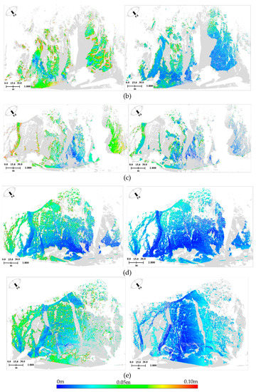
Figure 7.
Registration errors’ distribution of TLS stations from March 2013: (a–e), Pairwise registration errors and multi-station adjustment errors between T1 and T2, T2 and T3, T3 and T4, T4 and T5, and T5 and T6.
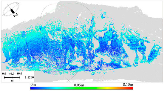
Figure 8.
Errors’ distribution of multi-station adjustment between UAV and TLS data.

Table 2.
Mean registration errors between UAV dense image points and TLS stations.
The left columns in Figure 7 suggest that the patch based pairwise registration can realize the coarse alignments between TLS stations. Table 2 shows that the mean errors of pairwise registrations can be controlled within 0.10 m. It illustrates the good robustness of this patch based registration method. The right columns in Figure 7 illustrate that the proposed multi-station adjustment can improve the registration accuracy effectively. The mean errors after multi-station adjustment can be controlled within 0.03 m (as shown in Table 2). This suggests that the initial values provided by pairwise registration are valid, thus preventing the multi-station adjustment from interfering with the local optimum. It also illustrates the effectiveness of the proposed multi-station adjustment method, which obtained the corrections of the registration parameters of each station by making full use of all locally closed loops, thus realizing a high accurate alignment between the TLS points and UAV dense image points. Moreover, Figure 7 and Table 2 show that the registration errors between station 2 and station 3 are relatively high (about 0.075 m). This is because extensive vegetation exists in the overlapping regions, leading to differences between the TLS stations from different views. However, the proposed method can still realize the registration between the stations, demonstrating a reliable and stable solution for the accurate registration of complex scenes.
3.1.3. Registration Results of Multi-Temporal TLS Surveys
According to Section 2.4 and Section 2.6, to reduce the GCPs and ensure the robustness of the registration, patch primitives were used to realize the coarse registration of TLS stations of the same period. Then, the UAV dense image points from September 2014 were taken as the reference framework to transform multi-temporal TLS point clouds into the control points’ coordinate system (WGS-84) by the proposed multi-station adjustment method. Finally, the mean registration errors between the UAV dense image points and multi-temporal TLS surveys were calculated to check the transformation accuracies. The registration results of the multi-station adjustment for each TLS survey are shown in Figure 9. The transformation results of the multi-temporal TLS surveys are shown in Figure 10. The mean errors between the UAV dense image points and five TLS surveys after multi-station adjustment are shown in Table 3, respectively.
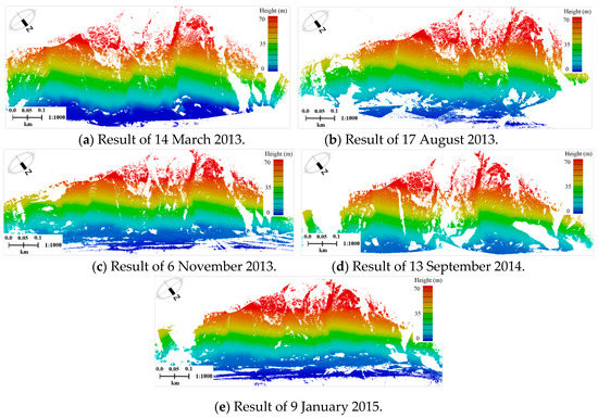
Figure 9.
Multi-station adjustment results of five surveys.

Figure 10.
Transformation results of multi-temporal TLS surveys (one color represents one temporal TLS point cloud).

Table 3.
Mean errors between UAV points and five TLS surveys after multi-station adjustment.
The statistical results in Table 3 demonstrate that the mean errors in the overlapping regions between five TLS surveys and the UAV dense image points are 0.023 m, 0.043 m, 0.016 m, 0.037 m, and 0.013 m, respectively, indicating that the registration between the TLS point clouds and UAV image dense points was achieved. In particular, visual checking found that the registrations between the cliff areas were also achieved. Such good registration results lay a solid foundation for the generation of high quality DEMs.
3.2. Experiments of Deformation Evaluation
DEMs of Each Survey and Deformation Maps between Multi-Temporal DEMs
Figure 11 shows the multi-temporal DEMs generated with a 0.2 m horizontal resolution of the study coastal area. To analyze the evolution of the terrain morphology, the terrain surface deformations over five time periods from March of 2013 to January of 2015 were calculated and are illustrated in Figure 12. The two adjacent temporal DEMs were also compared to investigate the extent of the deformation and are illustrated in Figure 13.
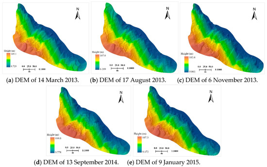
Figure 11.
Multi-temporal DEMs.
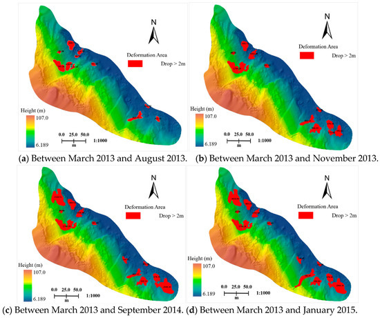
Figure 12.
Deformation maps with first survey.
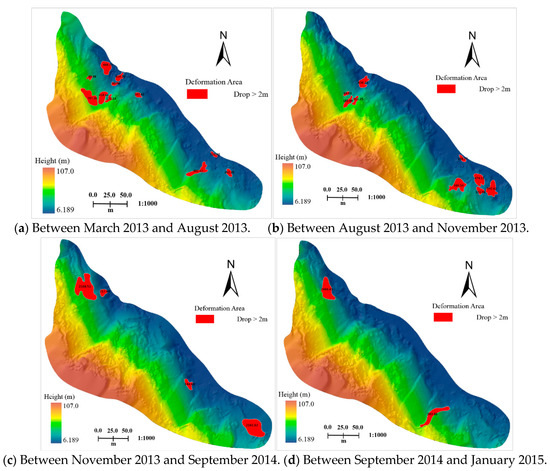
Figure 13.
Deformation between adjacent surveys.
As seen in Figure 11, the multi-temporal DEMs accurately reflect the elevations changes of each period time and describe the terrain relief and topography in detail. The terrain surface deformations for over half of the past two years were calculated in the whole study area from the five surveys, resulting in 14,024 m3 of total earthwork. Figure 12 shows that the terrain surfaces change obviously each year. The deformations are mainly located at the two sides of the mountain slopes, because these areas undergo large excavations every year, resulting in large terrain volume changes as illustrated in Figure 13a,c. Besides the influence of excavation activities, heavy rainfalls during the summer of 2013 also caused large topographic changes (Figure 13a).
4. Discussion
4.1. Slope and Aspect Maps of Multi-Temporal TLS Surveys
Slope and aspect maps for each survey were also made for the terrain morphological analysis. Both were derived from the above DEMs. The slopes were classified into nine classes ranging from 0° to 82°, with slopes greater than 82° merged into one class. The aspects were classified into 10 classes corresponding to the cardinal directions. Figure 14 illustrates the slope and aspect maps, respectively.
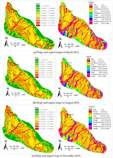
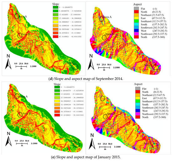
Figure 14.
Multi-temporal slope and aspect maps.
As shown in Figure 14, areas with slopes over 36° account for about 80% of the total study area. The aspect maps show that the largest areas are located in the northeast direction, contributing about 30% of the total area. Combining the slope and aspect maps, we found that the terrain relief is mostly along the northeast direction, which is also the main direction of the topographic changes. Besides, Figure 14 demonstrates that the slope and aspect maps also changed with the excavations or landslides. To demonstrate this clearly, we selected three areas (as the black circles show) from the areas of interest. Based on the slope and aspect information of the areas, the deformations of the slope and aspect are consistent with the topographic deformations shown in Section 3.2.
To demonstrate the topographic changes of the areas of interest further by combining the slope and aspect information, the aspect-slope scatter points’ maps of the first survey (March 2013) and last survey (January 2015) based on the slope and aspect maps of the three areas were provided. Figure 15 shows the aspect–slope scatter plot of these three areas.
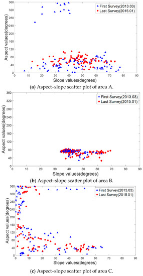
Figure 15.
Aspect–slope scatter plots of area A, B, and C (for each area, 100 points were selected uniformly from the aspect and slope map of the three areas).
Figure 15a shows that area A has a wide range of slope (from 10 to 80 degrees), and two main directions (northeast and northwest, 40 and 320 degrees). After the excavation or landslides, the aspect changed obviously. The direction of northwest (320 degrees) was changed to east (40 degrees). From Figure 15b, we can see that area B has a small change in the slope (from a range of 35–60 degrees to the range of 35–70 degrees), but little in the aspect. Figure 15c shows that both ranges of the slope and aspect are wide (0–65 degrees for slope, 0–360 degrees for aspect). It also suggests that area C is an isolated hill. From Figure 15c, it is shown that a small area has changed in both the slope and aspect (the top blue points disappeared).
4.2. Vertical Sections of Marker Pegs
The profiles of the filtered data from five surveys were further used for the terrain surface analysis of areas of interest. Five marker pegs were set at the areas of interest. These pegs were used to obtain vertical sections of each period of point clouds. The distribution of the marker pegs in March 2013 DEM is illustrated in Figure 16. For each peg position, the vertical section was interpolated along its aspect direction (as shown in Figure 17, each color represents each survey data).
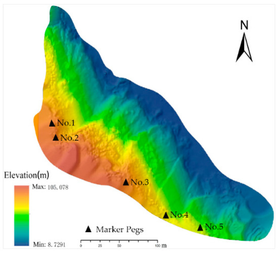
Figure 16.
Exhibition of the marker peg positions.
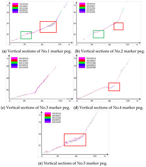
Figure 17.
Vertical sections of five marker peg positions.
Figure 17 illustrates that all the marker peg positions have large slopes, and the deformation areas are mainly located between 30 m and 70 m. The top portions of the vertical sections from the No.2 and No.3 marker pegs are missing. This is because dense vegetation exists there, and the filtered results do not affect the terrain analysis of the areas of interest. The green boxes in Figure 17a,b demonstrate that the No.1 and No.2 peg positions experienced obvious “erosion” that was mainly caused by excavation activities.
The red boxes in Figure 17a,e illustrate that the partial later surfaces are higher than the earlier surfaces, which suggests that serious landslides occurred there. Additionally, the red boxes in Figure 17b,d show that minor landslides occurred at the No.2 and No.4 marker peg positions. It is noteworthy that the portions above the four red boxes are very steep (slopes over 55°). Furthermore, comparison of the data shows that most of the landslides occurred between March and August 2013 (rainy season). Figure 17 demonstrates that the topographical changes of the marker pegs are consistent with the results in Figure 12 and Figure 13, demonstrating the accuracy and reliability of the proposed method.
5. Conclusions and Future Work
DEM analysis based on TLS datasets is a common method for deformation detection. To transform multi-temporal TLS surveys into the control points’ coordinate system, most existing methods depend on a variety of GCPs. However, the deployment of various GCPs is time-consuming and labor-intensive, and cumulative errors are not fully considered. Compared with the cumbersome deployment of GCPs, a mini-UAV with a consumer grade optical camera provides a more beneficial method. In this paper, we investigated a deformation method based on a new registration algorithm that accurately registers TLS scans to UAV dense image points with limited GCPs. To fulfill the task, we pairwise registered the TLS scans by extracting patch primitives, and introduced a locally closed loops based multi-station adjustment algorithm for the accurate alignment of TLS and UAV data. The captured data from TLS and UAV were then registered in a uniform spatial reference framework. Second, the deformations of the experimental area were detected and analyzed according to the results generated by the five period surveys. The statistical results demonstrated that the deformation areas and the terrain volumes changes were effectively located, showing the success and effectiveness of the proposed method. Compared with the control survey (error within 0.03 m), this method had less precision (considering the errors of dense image points and the registration errors, the error was about 0.10 m), but was adequate for the application of this paper.
Some issues are still worthy of attention. Such applications have only been focused on specific site locations, rather than allowinfgfor extensive use in a variety of study areas. This is due to the cumbersome nature of the TLS instruments, making it difficult to deploy them in harsh mountain environments.
Author Contributions
Y.Z. designed the algorithms as described in this paper, and was responsible for the main organization and writing of the paper. Other authors contribute to the data curation, investigation, and conceptualization.
Funding
Work described in this paper was jointly supported by National Science Foundation of China project under Grant No. 41701529, and University Science Research Project of Jiangsu Province, Grant No. 17KJB420004, and Startup Project for Introducing Talent of NUIST, Grant No. 2016r062, and OpenFund of State Laboratory of Information Engineering in Surveying, Mapping and Remote Sensing, Wuhan University, Grant No. 18S02.
Acknowledgments
The authors would like to thank Roderik Lindenbergh for providing the methods of topographic analysis.
Conflicts of Interest
The authors declare no conflict of interest.
References
- Lindenbergh, R.; Pietrzyk, P. Change detection and deformation analysis using static and mobile laser scanning. Appl. Geomat. 2015, 7, 65–74. [Google Scholar] [CrossRef]
- Guzzetti, F. Forecasting natural hazards, performance of scientists, ethics, and the need for transparency. Toxicol. Environ. Chem. Rev. 2016, 98, 1043–1059. [Google Scholar] [CrossRef] [PubMed]
- Salti, S.; Tombari, F.; Stefano, L.D. SHOT: Unique signatures of histograms for surface and texture description. Comput. Vis. Image Underst. 2014, 125, 251–264. [Google Scholar] [CrossRef]
- Lu, R.; Zhu, F.; Hao, Y.; Wu, Q. Simple and efficient improvement of spin image for three-dimensional object recognition. Opt. Eng. 2016, 55, 113102. [Google Scholar] [CrossRef]
- Kokkinos, I.; Bronstein, M.M.; Litman, R.; Bronstein, A.M. Intrinsic shape context descriptors for deformable shapes. In Proceedings of the 2012 IEEE Conference on Computer Vision and Pattern Recognition (CVPR), Providence, RI, USA, 16–21 June 2012; pp. 159–166. [Google Scholar]
- Rusu, R.B.; Blodow, N.; Beetz, M. Fast point feature histograms (FPFH) for 3D registration. In Proceedings of the IEEE International Conference on Robotics and Automation, 2009, ICRA’09, Kobe, Japan, 12–17 May 2009; pp. 3212–3217. [Google Scholar]
- Das, S.; Bhandarkar, S.M. Principal Curvature Guided Surface Geometry Aware Global Shape Representation. In Proceedings of the IEEE Conference on Computer Vision and Pattern Recognition Workshops, Salt Lake City, UT, USA, 18–22 June 2018; pp. 403–412. [Google Scholar]
- Bae, K.H.; Lichti, D.D. A method for automated registration of unorganised point clouds. ISPRS J. Photogramm. Remote Sens. 2008, 63, 36–54. [Google Scholar] [CrossRef]
- Bae, K.H.; Belton, D.; Lichti, D.D. A closed-form expression of the positional uncertainty for 3D point clouds. IEEE Trans. Pattern Anal. Mach. Intell. 2009, 31, 577–590. [Google Scholar]
- Ni, H.; Chen, S.; Gong, H.; Luo, Q.; Li, A. A Feature Point Based Registration of Brain Microscopic Images to the Reference Brain Atlas. In Proceedings of the International Conference on Photonics and Imaging in Biology and Medicine, Suzhou China, 26–28 September 2017; Paper W3A.84. Optical Society of America: Washington, DC, USA, 2017. [Google Scholar]
- Yang, B.; Zang, Y. Automated registration of dense terrestrial laser-scanning point clouds using curves. ISPRS J. Photogramm. Remote Sens. 2014, 95, 109–121. [Google Scholar] [CrossRef]
- Bosché, F. Plane-based registration of construction laser scans with 3D/4D building models. Adv. Eng. Inform. 2012, 26, 90–102. [Google Scholar] [CrossRef]
- Chen, Y.; Medioni, G. Object modeling by registration of multiple range images. In Proceedings of the IEEE International Conference on Robotics and Automation, Sacramento, CA, USA, 9–11 April 1991; pp. 2724–2729. [Google Scholar]
- Besl, P.J.; McKay, N.D. A method for registration of 3-D shapes. IEEE Trans. Pattern Anal. Mach. Intell. 1992, 14, 239–256. [Google Scholar] [CrossRef]
- Chen, J.; Belaton, B. An improved iterative closest point algorithm for rigid point registration. In Proceedings of the International Conference on Machine Learning and Cybernetics, Lanzhou, China, 13–16 July 2014; Springer: Berlin/Heidelberg, Germany, 2014; pp. 255–263. [Google Scholar]
- Dong, J.; Cai, Z.; Du, S. Improvement of affine iterative closest point algorithm for partial registration. IET Comput. Vis. 2016, 11, 135–144. [Google Scholar] [CrossRef]
- Li, W.; Song, P. A modified ICP algorithm based on dynamic adjustment factor for registration of point cloud and CAD model. Pattern Recognit. Lett. 2015, 65, 88–94. [Google Scholar] [CrossRef]
- Han, J.; Yin, P.; He, Y.; Gu, F. Enhanced ICP for the registration of large-scale 3D environment models: An experimental study. Sensors 2016, 16, 228. [Google Scholar] [CrossRef]
- Mohamad, M.; Ahmed, M.T.; Rappaport, D.; Greenspan, M. Super generalized 4PCS for 3D registration. In Proceedings of the 2015 International Conference on 3D Vision (3DV), Lyon, France, 19–22 October 2015; IEEE: Piscataway, NJ, USA, 2015; pp. 598–606. [Google Scholar]
- Kim, P.; Chen, J.; Cho, Y.K. SLAM-driven robotic mapping and registration of 3D point clouds. Autom. Constr. 2018, 89, 38–48. [Google Scholar] [CrossRef]
- Lawin, F.J.; Danelljan, M.; Khan, F.S.; Forssén, P.; Felsberg, M. Density Adaptive Point Set Registration. arXiv, 2018; arXiv:1804.01495. [Google Scholar]
- Zhu, J.; Meng, D.; Li, Z.; Du, S.; Yuan, Z. Robust registration of partially overlapping point sets via genetic algorithm with growth operator. IET Image Process. 2014, 8, 582–590. [Google Scholar] [CrossRef]
- Tombari, F.; Salti, S.; Stefano, L.D. Unique signatures of histograms for local surface description. In Proceedings of the European Conference on Computer Vision, Heraklion, Crete, Greece, 5–11 September 2010; pp. 356–369. [Google Scholar]
- Guo, Y.; Sohel, F.; Bennamoun, M.; Lu, M.; Wan, J. Rotational projection statistics for 3D local surface description and object recognition. Int. J. Comput. Vis. 2013, 105, 63–86. [Google Scholar] [CrossRef]
- Geng, N.; Ma, F.; Yang, H.; Li, B.; Zhang, Z. Neighboring constraint-based pairwise point cloud registration algorithm. Multimedia Tools Appl. 2016, 75, 1–18. [Google Scholar] [CrossRef]
- Williams, J.; Bennamoun, M. Simultaneous registration of multiple corresponding point sets. Comput. Vis. Image Underst. 2001, 81, 117–142. [Google Scholar] [CrossRef]
- Huber, D.F.; Hebert, M. Fully automatic registration of multiple 3D data sets. Image Vision Comput. 2003, 21, 637–650. [Google Scholar] [CrossRef]
- Zhu, J.; Li, Z.; Du, S.; Ma, L.; Zhang, T. Surface reconstruction via efficient and accurate registration of multi-view range scans. Opt. Eng. 2014, 53, 102104. [Google Scholar] [CrossRef]
- Guo, R.; Zhu, J.; Li, Y.; Chen, D.; Li, Z.; Zhang, Y. Weighted motion averaging for the registration of multi-view range scans. Multimedia Tools Appl. 2017, 77, 1–18. [Google Scholar] [CrossRef]
- Zheng, L.; Yu, M.; Song, M.; Stefanidis, A.; Ji, Z.; Yang, C. Registration of long-strip terrestrial laser scanning point clouds using Ransac and closed constraint adjustment. Remote Sens. 2016, 8, 278. [Google Scholar] [CrossRef]
- Xu, Y.; Gao, J. Research on point cloud registration error of terrestrial laser scanning. J. Geod. Geodyn. 2011, 31, 129–132. [Google Scholar]
- Ji, Z.; Song, M.; Guan, H.; Yu, Y. Accurate and robust registration of high-speed railway viaduct point clouds using closing conditions and external geometric constraints. ISPRS J. Photogramm. Remote Sens. 2015, 106, 55–67. [Google Scholar] [CrossRef]
- Vosselman, G. Slope based filtering of laser altimetry data. Int. Arch. Photogramm. Remote Sens. 2000, 33, 935–942. [Google Scholar]
- Baltsavias, E.P. A comparison between photogrammetry and laser scanning. ISPRS J. Photogramm. Remote Sens. 1999, 54, 83–94. [Google Scholar] [CrossRef]
- Martínez-Carricondo, P.; Agüera-Vega, F.; Carvajal-Ramírez, F.; Mesas-Carrascosa, F.J.; García-Ferrer, A.; Pérez-Porras, F.J. Assessment of UAV-photogrammetric mapping accuracy based on variation of ground control points. Int. J. Appl. Earth Obs. Geoinf. 2018, 72, 1–10. [Google Scholar] [CrossRef]
- Jebur, M.N.; Pradhan, B.; Tehrany, M.S. Using ALOS PALSAR derived high-resolution DInSAR to detect slow-moving landslides in tropical forest: Cameron Highlands, Malaysia. Geomat. Nat. Hazards Risk 2015, 6, 741–759. [Google Scholar] [CrossRef]
- Wang, S.; Chen, Y.; Chen, H.; Luo, S.; He, L.; Tong, L. Estimation of ground deformation in mountain areas with improved SAR interferometry. In Proceedings of the Geoscience and Remote Sensing Symposium, Beijing, China, 10–15 July 2016; pp. 5947–5950. [Google Scholar]
- Tang, Y. Small baseline subsets approach of DInSAR for investigating land surface deformation along the high-speed railway. Proc. SPIE 2014, 9260. [Google Scholar] [CrossRef]
- Ye, X.; Kaufmann, H.; Guo, X.F. Landslide monitoring in the Three Gorges area using D-InSAR and corner reflectors. Photogramm. Eng. Remote Sens. 2004, 70, 1167–1172. [Google Scholar] [CrossRef]
- Wei, M.; Sandwell, D.T. Decorrelation of L-band and C-band interferometry over vegetated areas in California. IEEE Trans. Geosci. Remote Sens. 2010, 48, 2942–2952. [Google Scholar]
- Klees, R.; Didier, M. Deformation measurements using SAR interferometry: potential and limitations. Geologie en Mijnbouw 1998, 77, 161–176. [Google Scholar] [CrossRef]
- Zhang, Y.; Meng, X.; Jordan, C.; Novellino, A.; Dijkstra, T.; Chen, G. Investigating slow-moving landslides in the Zhouqu region of China using InSAR time series. Landslides 2018, 1–17. [Google Scholar] [CrossRef]
- Niethammer, U.; James, M.R.; Rothmund, S.; Travelletti, J.; Joswig, M. Uav-based remote sensing of the super-sauze landslide: evaluation and results. Eng. Geol. 2012, 128, 2–11. [Google Scholar] [CrossRef]
- Nikolakopoulos, K.; Kavoura, K.; Depountis, N.; Kyriou, A.; Argyropoulos, N.; Koukouvelas, I.; Sabatakakis, N. Preliminary results from active landslide monitoring using multidisciplinary surveys. Eur. J. Remote Sens. 2017, 50, 280–299. [Google Scholar] [CrossRef]
- Torrero, L.; Seoli, L.; Molino, A.; Giordan, D.; Manconi, A.; Allasia, P.; Baldo, M. The Use of Micro-UAV to Monitor Active Landslide Scenarios. In Engineering Geology for Society and Territory—Volume 5; Springer International Publishing: Berlin/Heidelberg, Germany, 2015. [Google Scholar]
- Turner, D.; Lucieer, A.; De, J.; Steven, M. Time series analysis of landslide dynamics using an unmanned aerial vehicle (UAV). Remote Sens. 2015, 7, 1736–1757. [Google Scholar] [CrossRef]
- Peppa, M.V.; Mills, J.P.; Moore, P.; Miller, P.E.; Chambers, J.E. Accuracy assessment of a UAV-based landslide monitoring system. ISPRS-Int. Arch. Photogramm. Remote Sens. Spat. Inf. Sci. 2016, 41, 895–902. [Google Scholar] [CrossRef]
- Prokop, A.; Panholzer, H. Assessing the capability of terrestrial laser scanning for monitoring slow moving landslides. Nat. Hazards Earth Syst. Sci. 2009, 9, 1921–1928. [Google Scholar] [CrossRef]
- Johan, K.; Christophe, D.; Pascal, A.; Pierre, P.; Marion, J.; Eric, V. Application of a Terrestrial Laser Scanner (TLS) to the Study of the Séchilienne Landslide. Remote Sens. 2010, 2, 2785–2802. [Google Scholar] [CrossRef]
- Castagnetti, C.; Bertacchini, E.; Rivola, R. A reliable methodology for monitoring unstable slopes: The multi-platform and multi-sensor approach. In Proceedings of the SPIE, Earth Resources and Environmental Remote Sensing/GIS Applications V, Amsterdam, The Netherlands, 23–25 September 2014; Volume 9245, p. 92450J. [Google Scholar] [CrossRef]
- Yufu, Z.; Bisheng, Y.; Fuxun, L.; Xiongwu, X. Novel Adaptive Laser Scanning Method for Point Clouds of Free-Form Objects. Sensors 2018, 18, 2239. [Google Scholar]
- Brenner, C.; Dold, C.; Ripperda, N. Coarse orientation of terrestrial laser scans in urban environments. ISPRS J. Photogram. Remote Sens. 2008, 63, 4–18. [Google Scholar] [CrossRef]
- Haala, N.; Cramer, M.; Rothermel, M. Quality of 3D point clouds from highly overlapping UAV imagery. ISPRS—Int. Arch. Photogramm. Remote Sens. Spatial Inf. Sci. 2013, XL-1/W2, 183–188. [Google Scholar] [CrossRef]
- Fraser, R.H.; Olthof, I.; Maloley, M.; Fernandes, R.; Prevost, C.; Sluijs, J. UAV photogrammetry for mapping and monitoring of northern permafrost landscapes. ISPRS—Int. Arch. Photogramm. Remote Sens. Spat. Inf. Sci. 2015, XL-1/W4, 361. [Google Scholar] [CrossRef]
- Zhao, X.; Guo, Q.; Su, Y.; Xue, B. Improved progressive TIN densification filtering algorithm for airborne LiDAR data in forested areas. ISPRS J. Photogramm. Remote Sens. 2016, 117, 79–91. [Google Scholar] [CrossRef]
© 2019 by the authors. Licensee MDPI, Basel, Switzerland. This article is an open access article distributed under the terms and conditions of the Creative Commons Attribution (CC BY) license (http://creativecommons.org/licenses/by/4.0/).