Acceleration Compensation for Estimation of Along-Track Velocity of Ground Moving Target from Single-Channel SAR SLC Data


1
Department of Geoinformation Engineering, Sejong University, Seoul 05006, Korea
2
Department of Earth System Sciences, Yonsei University, Seoul 03722, Korea
*
Author to whom correspondence should be addressed.
Remote Sens. 2020, 12(10), 1609; https://doi.org/10.3390/rs12101609
Submission received: 30 March 2020
/
Accepted: 13 May 2020
/
Published: 18 May 2020
(This article belongs to the Special Issue Earth Observation from KOMPSAT Optical, Thermal and Radar Satellite Images)
Abstract
:Across-track acceleration is a major source of estimation error of along-track velocity in synthetic-aperture radar (SAR) ground moving-target indication (GMTI). This paper presents the theory and a method of compensating across-track acceleration to improve the accuracy of along-track velocity estimated from single-channel SAR single-look complex data. A unique feature of the proposed method is the utilisation of phase derivatives in the Doppler frequency domain, which is effective for azimuth-compressed signals. The performance of the method was evaluated through experimental data acquired by TerraSAR-X and speed-controlled and measured vehicles. The application results demonstrate a notable improvement in along-track velocity estimates. The amount of along-track velocity correction is particularly significant when a target has irregular motion with a low signal-to-clutter ratio. A discontinuous velocity jump rather than a constant acceleration was also observed and verified through comparison between actual data and simulations. By applying this method, the capability of single-channel SAR GMTI could be substantially improved in terms of accuracy of velocity, and moving direction. However, the method is effective only if the correlation between the actual Doppler phase derivatives and a model derived from the residual Doppler rate is sufficiently high. The proposed method will be applied to X-band SAR systems of KOMPSAT-5 and -6.
1. Introduction
A unique and popular application of synthetic-aperture radar (SAR) is the monitoring of moving targets [1,2,3,4,5,6], which is a SAR application field of ground moving-target indication (GMTI) [7,8,9,10,11,12]. The main topics of SAR GMTI are the detection of targets and the estimation of their velocities. In a normally focused SAR image in which stationary ground is presumed, it is well known that moving objects are rendered by azimuthal displacement, smearing, and range walking [1,2]. The movement of a target during the antenna observation period results in distortion of the Doppler centroid (or Doppler centre frequency) and Doppler rate (or azimuth chirp rate). The distorted Doppler centre frequency contributes to the azimuthal displacement in ordinary SAR images, and the image smearing in the azimuth is caused by the abnormal Doppler rate. The range walk reflects the distance moved by a target in range during the antenna integration time. Thus, there are two issues associated with ground moving targets observed by SAR: the first is to generate an improved SAR image in which moving targets are additionally focused and the position of the target is shifted to the true position through an accurate estimation of the Doppler parameters. Many papers discuss the SAR image signatures of moving targets and propose methods for residual focusing [12,13,14,15,16,17,18,19]. On the contrary, SAR GMTI focuses on the analysis of target motion itself rather than image correction. A number of papers propose various methods for SAR GMTI [8,20,21,22,23], and multi or at least dual-channel SAR systems are efficient and effective for the detection and velocity estimations of ground moving targets [8,10,11,12,17,24,25,26,27,28,29,30]. However, data of space-borne single-channel SAR systems are currently far more abundant and are easier to access by general users than space-borne multi or dual-channel SAR data. Therefore, it is far more practical to use space-borne single-channel SAR systems for SAR GMTI, although space-borne dual-channel SAR systems have a superior capabilities in terms of the detection rate and the accuracy of the retrieved velocity [5,18,31,32,33]. In addition, raw SAR signals of most current space-borne SAR systems are not available to general users because the total size of the raw signal data is too large to transfer to users. Instead of raw SAR signals, single-look complex (SLC) data are fundamental processed SAR data available to general users. This paper focuses on compensating across-track acceleration to improve the accuracy of the along-track velocity of ground moving targets from SLC data obtained by single-channel SAR systems.
Accurate measurement of the instantaneous Doppler phase plays a key role in target-velocity estimation and high-quality image focusing. The instantaneous Doppler phase is a function of relative distance between the SAR antenna and target. The distance between the antenna and target varies not only with antenna path, but also with target motion. The across-track velocity of a given target results in the distortion of the first-order Doppler phase in the azimuth time domain, or equivalently, in a shift in the Doppler centroid in the Doppler frequency domain. It is relatively straightforward to retrieve the across-track velocity by measuring the relative shift in the Doppler centre frequency from the SAR signals. On the contrary, it is more complicated to accurately estimate the along-track velocity from single or multi-channel SAR data. A number of methods have been proposed for the accurate estimation of the Doppler rate, such as methods using matched filter banks [9,25,29], methods based on a joint time-frequency (TF) analysis [16,34,35,36], and methods utilizing a fractional Fourier transform (FrFT) [31,37,38]. A principal tactic for Doppler rate estimation is to search the optimal Doppler rate that results in the highest compression of the target signal. Minimum entropy is commonly used as a criterion for optimal SAR focusing [39,40,41]. Difficulty arises from the fact that the along-track velocity and across-track acceleration commonly contribute to the second-order Doppler phase or the Doppler rate. Consequently, it is problematic to reconstruct two unknown parameters—the along-track velocity and across-track acceleration—from a single observation, the Doppler rate. Thus, most proposed GMTI methods and literature assume targets moving with constant velocity [8,9,11,19,20,21,42]. In reality, the across-track acceleration is often not negligible for both on-land vehicles [10,43] and vessels at sea [42]. While the across-track acceleration is not a main parameter of interest for most SAR GMTI applications, it is frequently a major source of error in the estimation of the along-track velocity component. The Doppler phase associated with target acceleration has been theoretically examined by various authors, including those of [1,13,44]. The effects of acceleration on velocity estimation, particularly from dual-channel SAR data, are well discussed in detail in [10]. Although the effects of acceleration are well known, an effective method of acceleration compensation is yet to be developed. This is mainly because of the fundamental limitation that the separation of across-track velocity from across-track acceleration cannot be achieved with a single parameter, the Doppler rate. Thus far, only one method has been proposed to compensate the effects of target acceleration [43]. Even the method proposed in [43], based on a joint time-frequency analysis through the Wigner–Ville distribution, is only effective for dual-channel SAR systems and requires azimuth-uncompressed signals. Thus far, to the authors’ knowledge, there are no papers that propose a method of effectively compensating the across-track acceleration in single-channel SAR SLC data.
This paper proposes a method of compensating the across-track acceleration in single-channel SAR GMTI to improve the estimation accuracy of the along-track velocity of ground moving targets. The method was applied to single-channel SAR SLC data. A unique feature of the proposed method is the estimation of the Doppler phase variation in the Doppler frequency domain instead of time-domain estimation. Combined with the Doppler rate obtained by conventional methods, additional information on the Doppler phase variation in the Doppler frequency domain compensates for the effects of across-track acceleration on the estimation of the along-track velocity in single-channel SAR GMTI. Since there are one-on-one relations between the azimuth time and the Doppler frequency, the variation in Doppler phase with respect to the Doppler frequency directly presents the time-varying Doppler phase, and vice versa. Consequently, the Doppler phase variation in the Doppler frequency domain provides information of time-varying, across-track velocity or average acceleration within a short period. For this purpose, the Doppler phase response of ground moving targets in the Doppler frequency domain is reorganized through the principle of stationary phase, as summarized in Appendix A. The frequency variation in the Doppler phase can be estimated efficiently by applying a rotational invariance technique (ESPRIT) algorithm, which was originally developed for the estimation of signal parameters in the time domain via rotational invariance techniques [45,46]. A modified version of ESPRIT is discussed in [33], particularly for Doppler frequency estimation from SAR signals. Once the frequency-varying Doppler phase is obtained, particularly around the Doppler centroid, the across-track acceleration can be effectively compensated to improve the estimation accuracy of the along-track velocity component.
The organization of this paper is as follows. In Section 2, the theoretical background of the proposed method is introduced. The Doppler phase of the azimuth-compressed SAR signal in the Doppler frequency domain is formulated and discussed. The relationship between the target’s motion parameters—velocity and acceleration—and the Doppler phase in the Doppler frequency domain is examined. Section 3 describes the ground truth data and the TerraSAR-X imagery used in this study. Speed-controlled vehicles were used for the experiment and their velocities were measured using a GPS system. Section 3 also outlines the processing flow for compensating across-track acceleration to improve the estimation accuracy of the along-track velocity from single-channel SAR SLC images. The results obtained by applying the proposed method to the experimental data are discussed in Section 4. The along-track velocity estimates before and after the acceleration compensation are compared to the GPS velocities, and the improvements achieved by the proposed method are demonstrated. Limitations of the method are also discussed. A summary of the proposed method and results are presented in the conclusions, followed by Appendix A, in which the Doppler phase of the azimuth-compressed SAR signals in the Doppler frequency domain is derived.
2. Theoretical Background
The one-dimensional SAR signal can be simplified as
where is a rectangular function with an azimuth integration time over a single target. The range between the antenna and a ground moving target is approximated up to the third order of the azimuth time given by (Sharma, 2006)
where is the range between the antenna and a target; the azimuth time or slow time; the ground range; the along-track velocity of the antenna; the azimuth (or along-track) and across-track velocity of the target, respectively; the azimuth and across-track acceleration of the target, respectively; and the time derivative of across-track acceleration of the target. Since the target velocity and acceleration terms are very small compared with the range,, the range can be further approximated as:
By substituting Equation (3) into Equation (1), the SAR signal is given by
where
and is the Doppler centre frequency, the Doppler frequency rate of the Doppler rate, and the antenna elevation angle. Parameters , are defined by Equations (8) and (9), respectively, according to the target motion.
The point target spectrum of the azimuth-compressed SLC signal in the Doppler frequency domain is given by
Thus, a compressed point target within the SLC is approximated to a function with a phase of a third-order polynomial in the Doppler frequency domain, as in Equations (10) and (11). Realistic ranges of , , and are summarized in Table 1, and the Doppler rate is approximately 5500 Hz/s. Considering the value range of each parameter, the linear, quadratic, and cubic phases are mainly governed by the residual Doppler centre frequency , residual Doppler rate parameter , and , respectively.
Under favourable signal-to-clutter ratios (SCR) in instances larger than 7.7 dB in the sea [42], it is normally possible to precisely estimate the coefficient of quadratic phase in Equation (12) or the residual Doppler rate
using only a few tens of azimuth samples around the target. There are various methods with which to estimate the quadratic phase term, such as a FrFT-based method in the time domain [31,37,38,47] or a Doppler-rate filter-bank method [9,25,29]. Both approaches search for a quadratic coefficient until the azimuth signals are optimally compressed. Minimum entropy is a popular criterion for optimal azimuth compression [39,40,41,48]. The sub-aperture method is also useful [13,27]; it does not require the criterion of optimal azimuth compression. However, the accuracy of the sub-aperture method is usually less than those of the FrFT or Doppler-rate, filter-bank-based methods. By applying a suitable method, the quadratic coefficient in Equation (12) can be estimated independently. The detailed discussion of these methods is beyond the scope of this research. The second term in the bracket of Equation (13) is less than the order of 10−3 and is negligible. As in Equation (8), the residual Doppler rate is usually dominated by the along-track velocity , provided there is a constant across-track velocity, and consequently, the along-track velocity can be retrieved from the estimate with the assumption of negligible across-track acceleration. However, as discussed in [10], it is difficult to separate the along-track velocity from the across-track acceleration if the across-track acceleration is significant from single or dual-channel SAR observation. While most applications are interested in the along-track and across-track velocity components , the non-negligible across-track acceleration frequently causes serious errors in along-track velocity estimation. It might not be possible to separate the distribution of the estimate in Equation (8) from that of without additional observations if the across-track velocity increase is ideally linear with a constant , as discussed in [10]. However, the variation in across-track velocity is not always linear in reality. In this paper, we show that the time variation in can be measured in the Doppler-frequency domain, and the measured time variation in is used for compensation of the over or under-estimation of the along-track velocity , initially calculated from the estimate with the assumption of a zero across-track acceleration.
Since there is a one-on-one relation between the slow time and the Doppler frequency, it is possible to determine the time variation in if the frequency variation in is estimated. Now, let us consider the phase derivative of Equation (12) to yield
The quadratic phase in Equation (12) is the residual Doppler rate caused by the azimuth velocity and across-track acceleration. After estimation of the residual Doppler rate coefficient, the average slope in the Doppler-frequency domain is given by
The linear phase model (Equation (15)) can be easily obtained from estimated through an optimal residual compression. However, it must be emphasized that the residual Doppler rate parameter estimated on the basis of optimum azimuth compression represents a global average of the residual Doppler rate over the full azimuth integration time caused by the target motion. If the Doppler phase derivatives in Equation (14) are subtracted from the quadratic frequency phase model (Equation (15)), then the residual Doppler phase derivative is given by
The relationship in Equations (3), (12) and (16) is derived on the basis of an ideal target motion, which assumes that the target moves at a constant across-track velocity with a linear increasing or decreasing rate of over the entire antenna integration time. Then, is a function of the along-track velocity and the across-track acceleration of the target defined by Equation (8). If the behaviour of ground target motion is ideal, as explained, the residual Doppler phase derivative in Equation (16) must be a simple quadratic function. However, the deviation in from the simple model of Equation (15) is significantly higher for most real targets. The deviation mainly accounts for a variation in the Doppler centre frequency with respect to frequency, or equivalently to slow time. Changes in the across-track velocity naturally result in changes in Doppler centre frequencies, as in Equation (5).
The velocity and acceleration model assumed in Equation (2) is a linear velocity variation such that
However, the velocity variation in ground moving targets is often irregular or discontinuous, rather than exhibiting a linear increase or decrease. Instead of a linear variation in velocity with a constant acceleration, here we consider a general velocity variation model such that
where is the time-varying deviation from mean velocity . This velocity model accommodates the local or instantaneous variation in target velocity during the antenna integration time, regardless of whether the variation is linear. The core idea behind the proposed approach is that a realistic behaviour of target motion over the full integration time is either non-linear or discontinuously deviated from a mean velocity, rather than exhibiting an ideal linear increase or decrease. In fact, we found that a discontinuous model is frequently more practical for a real ground target, and a typical example is shown in the following section. Then, the across-track acceleration can be considered an accumulated effect of across-track velocity variation. The across-track velocity variations around the broadside time of the antenna-boresight crossing time are particularly interesting. The across-track velocity variation is more easily and precisely estimated as a variation in in the Doppler frequency domain because the value range of is far larger than other coefficients in Equation (16). Instead of a direct measurement of acceleration or linear slope of velocity change, here we estimate the time-varying velocity or equivalent at each corresponding frequency. Now, let us introduce a frequency-varying, residual Doppler centre frequency from Equations (5) and (18), defined by
where
and are normally well satisfied.
A main advantage of the estimation of phase derivatives in the Doppler frequency domain rather than in the time domain is as follows: the peak-to-clutter spectrum ratio around the residual Doppler centre frequency in the frequency domain is superior to that in the time domain. This can be explained by the fact that the clutter signals seriously affect the target signals according to the distance and the clutter power. This causes a serious limitation in the total number of useful azimuth samples around the target for estimation, and a total observation time that is often too short to estimate the velocity variation or acceleration from azimuth-compression SLC data. On the contrary, the clutter spectrum in the frequency domain spreads over entire frequencies, whereas the target signal is concentrated around the residual Doppler centre frequency ; therefore, a wide bandwidth can be used for the estimation in the Doppler frequency domain. There is a one-on-one relationship between the azimuth time and Doppler frequency
where represents an absolute value and the azimuth time is assumed zero at the antenna boresight crossing the target. Consequently, a wide bandwidth for the estimation implies that the total observation time for velocity variation or acceleration increases proportionally to the bandwidth involved in the estimation. In addition, a sample interval for phase differentiation can be easily handled by zero padding before taking a discrete Fourier transform.
By substituting Equation (19) into Equation (16), we have
up to the first order of . The first term is a constant and is not of interest. The constant term of the Doppler phase derivatives is governed not only by the average across-track velocity , but also by the position of the target due to the time-shift property of the Fourier transform. Consequently, the constant term is practically meaningless to examine. The residual Doppler centre frequency is normally determined by phase differentiation in the time domain or a peak of the Doppler spectrum in the frequency domain. The quadratic coefficient of Equation (22) is usually very small, as in Table 1 and Equation (9), for most targets. However, its contribution is sometimes not negligible when the along-track acceleration is unusually large. In such a case, the asymmetric feature of the compressed azimuth signal is significant; a typical example is shown in the following section. The second term—the residual Doppler centre frequency as a function of frequency—is our main interest. For general ground moving targets, the variation in is a measure of the time-varying across-track velocity , as in Equation (20). The behaviour of around is particularly informative. Conditions for the estimation of from Equation (22) are discussed in the next section. Thus, it is possible to retrieve a residual across-track acceleration if the variation in residual Doppler centre frequency is estimated in the Doppler frequency domain.
Now, let us define an across-track acceleration equivalent as follows.
where is a certain bandwidth for the estimation around the residual Doppler centre frequency, which can be determined by considering the noise level of the Doppler spectra. The acceleration defined in Equation (23) is an average acceleration over the period of centred at . The time length can be extended to a full antenna integration time but is practically limited by considering the SCR of each target. The difference in Doppler centre frequency variation in Equation (23) can be measured from Equation (22) such that
Since , the second term of Equation (24) is very small compared with the first term, and is negligible for most cases, unless , or equivalently, the along-track acceleration , is very large. However, a target with a very large is sometimes dominant in the Doppler phase derivatives of Equation (22). In such a case, the Doppler phase derivatives and the model from the residual Doppler rate in Equation (16) have a low correlation, and a different tactic is required. In the practical implementation of Equation (24), it is better to apply the method of least squares over the bandwidth of to determine the variation in residual Doppler centre frequency. Although the acceleration estimated by Equation (23) may not be sufficiently precise to account for actual across-track acceleration, it is very useful to compensate for the over or under-estimated along-track velocity . From Equation (8), the acceleration-compensated along-track velocity is computed by
To perform the phase derivations of Equation (14) in the Doppler frequency domain, it is effective to apply the ESPRIT method [33,45,46] with a certain length of sliding window to the Fourier-transformed SAR SLC data. Various lengths of sliding window were tested, and a quarter of a full-length Doppler spectrum, N/4, was the most effective with a Hamming window function. The interpretation of Equation (14) is similar to joint time-frequency analysis because there is a one-to-one relation between the Doppler frequency and the azimuth time for a given target. However, there is a difference in the dependent variable between the joint time-frequency analysis and Equation (14). The joint time-frequency analysis is carried out in the time domain, and consequently, the resulting dependent variable is a Doppler frequency according to the azimuth time. However, Equation (14) has phase derivatives in the Doppler frequency domain, and consequently, the dependent variable is a Doppler phase derivative in the frequency domain according to Doppler frequency, or equivalently, the azimuth time. Thus, Equation (14) presents the variation in residual Doppler centre frequency according to the azimuth time; the changing rate and pattern for a given bandwidth are meaningful, whereas the absolute value is meaningless.
A flat earth is assumed for the derivation of Equation (25). However, it is mandatory for a space-borne SAR system to apply an orbital configuration on computation of the velocity variation from the variation in Doppler centre frequency. This is achieved by applying the configuration explained in [49]. Correction for an orbital SAR system was applied to all results in this study.
3. Data and Processing
3.1. Field Experiment and Data
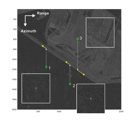
SAR SLC data acquired by TerraSAR-X strip-map mode were used to validate the proposed method. To obtain ground truth data, two truck-mounted corner reflectors were operated with a controlled speed along a straight coastal road during TerraSAR-X data acquisition, as seen in Figure 1. The speed-controlled trucks equipped with corner reflectors are denoted “1” and “2” (hereafter referred to as vehicle 1 and vehicle 2), respectively, in Figure 1. They had a common along-track velocity of −6.11 m/s, as listed in Table 2. The along-track velocity of the vehicle denoted “3” (hereafter referred to as vehicle 3) in Figure 1 was +10.11 m/s. Vehicle 3 was not equipped with a corner reflector. The negative sign of the along-track velocity represents the movement direction of the vehicle approaching the antenna, whereas the positive sign represents the direction away from the antenna. For more details concerning the field experiment, refer to [7]. The speed of the vehicle was measured by an onboard GPS system that recorded position and speed at a time-interval of one second. Although the GPS data interval of one second is sufficient to examine the average velocity of the moving target, it is not sufficiently short to analyse the instantaneous acceleration of the moving target. The antenna-integration time for the point target was approximately 0.7 s.
3.2. Processing for Acceleration Compensation
The processing flow of the proposed method for compensating the along-track velocity of a ground moving target from single-channel SAR SLC data is summarized in Figure 2. Detection of ground targets within a given SAR SLC image is the first step. There are various tactics for SAR GMTI, and the sub-aperture mismatching method is popular [13,27]. However, a detailed description of the detection method is beyond the scope of this paper. Once a ground moving target is detected in a SAR SLC image, data of a sub-window are taken for the next velocity estimation. This study used a sub-window of 129 by 3 in azimuth and range, respectively. For ordinary vehicles on land, three to five range bins are sufficient for velocity estimation, but the number of range bins for the sub-window can be increased freely as required, depending on the size and speed of target. The next step is to estimate the Doppler parameters of the residual Doppler centroid and Doppler rate. Numerous tactics and methods have been developed for the Doppler centroid estimation. Some popular conventional methods are [50,51,52,53]. In addition to these conventional methods, additional sophisticated approaches include [20,34,36,54,55]. Recently, an approach based on a combination of ESPRIT and linear least squares was proposed in [33], in which the advantages and disadvantages of different methods are discussed in detail. Conventional approaches based on image-blurring caused by Doppler rate mis-matching, such as [7,15,56] and matched filter banks [9,25,29], have been used for Doppler rate estimation. Joint time-frequency analysis is also popular for estimating the Doppler rate [16,20,34,57]. Other methods based on the cubic-phase function proposed by [58,59,60] have significantly improved the computational efficiency and performance. FrFT has a great advantage in Doppler rate estimation, particularly when applied to azimuth-compressed SLC data [31,37,38,42,47]. Doppler rate estimation methods such as the filter-bank method and FrFT-based method search an optimum Doppler parameter until the signals from the target reach maximum compression. It is then necessary for a criterion to determine the degree of chirp signal compression. The minimum entropy is commonly used as a criterion of SAR focusing [39,40,41,48], and was adopted in this study.
After the Doppler centroid and residual Doppler rate were estimated in the time domain, a one-dimensional Fourier transform in the azimuth dimension with a length of N was applied to the sub-windowed signals. Doppler phase derivatives were then obtained by applying a sliding window of simplified ESPRIT. After numerous tests, the length of N/4 was found to be the most effective length of the sliding window.
From the residual Doppler rate estimated in time, a linear phase model in the Doppler frequency domain is given by Equation (15), and it is subtracted from the Doppler phase derivatives, as in Equation (16).
4. Application Results and Discussion
The first example is of a speed-controlled, on-land vehicle with a typical behaviour of velocity variation. Figure 3 presents the results from the speed-controlled vehicle 1 in Figure 1, whose velocity was measured by an onboard GPS system. In Figure 3a, the solid black line represents the Doppler spectrum, and its Doppler centre frequency was determined by the mass centre of the Doppler spectrum and by the ESPRIT method [45,46] in the time domain. The Doppler phase derivatives in the Doppler frequency domain are displayed with a blue line in Figure 3a, which also shows the variation pattern around the Doppler centre frequency. The solid red line in Figure 3a was obtained by the residual Doppler rate estimated in the time domain and has a squared correlation coefficient of 0.97 with the Doppler phase derivatives.
In fact, the proposed method is only valid with a high correlation between the residual Doppler rate model and the Doppler phase derivatives, and here we set 0.9 as the lower boundary for a valid squared correlation coefficient. Note that the phase derivatives deviate from the model straight line around the Doppler centre frequency, and the deviation contributes to the across-track acceleration. After subtracting the residual Doppler rate model (red solid line) from the Doppler phase derivatives (blue solid line), as in Equation (21), and multiplying by the residual , the residual is given as Figure 3b. The velocity variation around the beam centre crossing time, or equivalently, around the Doppler centre frequency, can be estimated from the average slope, as in Figure 3b. In this case, a bandwidth of 1717 Hz, or equivalently, 0.316 s around the Doppler centre frequency, was used for estimation of the across-track acceleration. The estimated across-track acceleration was 0.0681 m/s2, from which the along-track velocity was corrected from −8.54 to −6.89 m/s. The GPS-measured along-track velocity was −6.61 m/s (−23.8 km/h), and the absolute error was reduced by 1.65 m/s (5.94 km/h), from 1.93 m/s to 0.28 m/s, through the proposed acceleration compensation.
A simulation was carried out to confirm the estimation, as summarized in Figure 4. From the estimated acceleration of 0.681 m/s2 and the shape of the residual velocity variation (blue solid line in Figure 3), we assumed a velocity variation as a step function as in Figure 4a, rather than a linear model. The velocity variation model in Figure 4a presents a velocity jump of 0.03 m/s over 0.45 s, from −13.618 to −13.648 m/s.
All parameters for the simulation were adopted from the actual data from header information or estimated data from the SLC data used: the system and residual Doppler rate were 5438.1 and −11.2 Hz/s, respectively, with a PRF of 3815.5 Hz. Raw signals were simulated first, and then a general azimuth compression was applied to simulate the SLC data. As shown in Figure 4b, the Doppler phase derivatives obtained from the velocity jump model (red dashed line) match very well with that of the actual SAR data (blue solid line) with a squared correlation coefficient of 0.999. On the contrary, linear velocity increase or decrease models simply change the slope of the straight line, which does not account for the actual velocity variation pattern in Figure 4b.
The second example summarized in Figure 5 is also a frequently observed typical case of vehicles on land. The vehicle denoted “3” (hereafter referred to as vehicle 3) showed a low SCR of 9.7 dB. Under low-SCR conditions, the signals from a given target are seriously distorted by surrounding clutter. Compared with vehicles 1 and 2, which were imaged on the water surface, the SCR of vehicle 3 was only 9.7 dB, as in Table 2. Since the estimation of the Doppler rate in time or Doppler frequency domain is the average value over the antenna integration time, it often leads to an incorrect value when the signals are distorted by those from neighbouring strong scatterers or clutter. As in Figure 5a, the Doppler spectrum (black solid line) was seriously corrupted by clutter, and its antenna beam pattern was largely distorted at high Doppler frequencies. However, the Doppler spectrum is well preserved around the Doppler centre frequency (black dashed line), and it is better to estimate the along-track velocity only around the centre frequency (i.e., at antenna boresight crossing time) rather than over a full bandwidth (or full antenna integration time). The initial estimate of the Doppler rate (red solid line in Figure 3a) was significantly overestimated, and consequently resulted in a large error in along-track velocity. The Doppler phase derivative (blue solid line) significantly deviated from the Doppler rate model, but maintained a high correlation of 0.99 between the model and the actual Doppler phase derivatives over 45% of the full bandwidth around the Doppler centre frequency, as seen in Figure 5a. The estimated across-track acceleration was −0.155 m/s2. The estimation error of the along-track velocity significantly reduced from 5.27 to 1.49 m/s by compensating the cross-track acceleration as in Table 2. This example demonstrates a main advantage of the proposed method such that the estimation using limited bandwidth around the Doppler centre frequency provides an improved accuracy compared to estimation over the full antenna integration time.
The improvement by adopting the proposed method is obvious, as summarized by the two resulting velocity vectors in Figure 6. The ground truth along-track velocity was 10.11 m/s. While the initial estimate of the along-track velocity was 15.38 m/s without acceleration compensation, the along-track velocity was reduced to 11.60 m/s after applying the proposed acceleration compensation. Through the acceleration compensation, the total velocity reduced from 25.2 m/s (90.8 km/h) to 23.1 m/s (83.2 km/h). With correction of the along-track velocity, the heading direction was adjusted by 7.5° and became parallel to the road. An improved heading direction provides very useful information for the interpretation of ground moving targets when compared with roads or other ground structures.
The third example in Figure 7 is for the case of vehicles with cubic or higher-order motion. The vehicle denoted “2” (hereafter referred to as vehicle 2) in Figure 2 was one of the speed-controlled trucks for the field experiment. The speed and heading direction were designed to be identical to those of vehicle 1. However, the vehicle apparently moved with slightly different behaviour. While the Doppler spectrum of vehicle 3 (Figure 7a) is very similar to that of vehicle 1 (Figure 3a), the shape of the phase derivatives is not linear, as in Figure 7a. Consequently, the residual Doppler rate model (blue solid line) based on Equation (14) does not accurately account for the actual Doppler phase derivatives (red solid line) with a very low squared correlation coefficient of 0.11. Since the squared correlation coefficient is far lower than 0.9, the proposed method is not effective for the estimation of across-track acceleration.
The proposed method is only valid if the squared correlation coefficient between the Doppler rate model and the actual Doppler phase derivatives is sufficiently high; for instance, it was 0.9 in this study, over the bandwidth of estimation involved. For vehicle 2, cubic-phase motion was apparently significant, as seen in Figure 2. In such a case, the Doppler phase derivative is used for analysis of a cubic-phase motion and residual compression instead of estimating the across-track acceleration. The Doppler phase derivatives in Figure 3a imply that the contribution of the last term in (21) is significant. Recall that is a function of the along-track acceleration and time derivative of the across-track acceleration, as defined in Equation (9), which are not the main features of interest for this study or most users. However, this parameter—if not small—is useful for residual compression; a best-fitted cubic-phase model was obtained using 50% of the full bandwidth around the Doppler centre frequency, as in Figure 3b. Figure 8 displays the original and residual compressed signals. An optimal quadratic phase was first estimated on the basis of the minimum entropy criterion, and then a residual compressed signal (blue solid line) was obtained by removing the quadratic phase from the original SLC signal (black solid line). This residual compression is a general residual compression process and results in a slightly further compressed signal of vehicle 2, as in Figure 8. Entropy is a popular criterion for evaluating residual focusing quality of a point target, and is defined in [39,40].
where
and is a two-dimensional summation of the power image, and an SLC data at the nth azimuth sample and mth range bin within a sub-scene.
The values of the original model and the model with the removed quadratic-phase signals in Figure 8 are 2.646 and 2.627, respectively, which implies that the residual compression by the optimal quadratic-phase model is not large. On the contrary, the entropy significantly reduced to 2.148 after the residual compression by the cubic-phase model, as seen in Figure 8. The original SLC signals rendered two peaks around the centre of the target. The residual compression by the quadratic-phase model slightly reduced the left peak, while increasing the right peak; however, it remains unclear whether there are two peaks or one peak with asymmetric side-lobes. After the residual compression by the cubic-phase model, it is clear that the target consists of one point target in the shape of typical sinc function. The results strongly support that the along-track acceleration was dominant at moment of SAR observation, while the across-track acceleration was not significant. Since the residual compression was done by a cubic-phase model, there exists asymmetry of the second and higher-order side-lobes, as discussed in [7].
In summary, the motion of ground vehicles or other moving targets in reality is complicated. A simple model of continuous and linear acceleration often cannot account for the actual motion of the ground moving target; however, accurate measurement of acceleration is usually neither easy nor a main interest of most SAR applications. Moreover, most onboard GPS systems are not suitable for measuring acceleration occurring over less than one second. Instead, it is necessary for most SAR ground-moving target applications to measure velocity as accurately as possible. Appropriate across-track acceleration compensation for the correction of the along-track velocity component is a major concern of this study. The proposed method is effective and efficient for the correction of along-track velocity as a consequence of the precise estimation of across-track acceleration from single-channel space-borne SAR SLC data.
5. Discussion
The proposed method has various advantages. First, no method has been proposed thus far (to the authors’ best knowledge) for estimation of across-track acceleration from a single-channel SAR SLC data, although a few methods have been proposed to utilize raw or range-compressed signals from multi-channel SAR systems. However, raw SAR signals obtained by multi-channel SAR systems are rarely available to general users, whereas single-channel SAR SLC data are currently abundant. In addition to data availability, the proposed method utilizes the estimation in the Doppler frequency domain rather than that in the time domain. This approach to utilization of the Doppler frequency domain has not been proposed previously. Before azimuth compression, the signals of a given target extend easily up to several thousands of samples. However, the signals of a target in SLC data extend to only less than a few tens of samples because the range and azimuth are already compressed, which makes it difficult to precisely measure the acceleration of the target using a limited number of samples. On the contrary, the Doppler spectrum of a ground moving target usually maintains its antenna pattern over a considerable portion of Doppler bandwidth. While the Doppler spectral energy of neighbouring weak scatterers and clutter spread out over the entire bandwidth, the spectral power from a target concentrates around the residual Doppler centre frequency, following the antenna beam pattern. The total number of samples in the Doppler frequency domain can also be managed simply by padding zeros before the Fourier transform. Thus, the estimation in the Doppler frequency domain has a great advantage over that in the time domain.
However, the proposed method has some limitations. As in Equation (15), the method should first remove the linear slope obtained independently as an optimum residual Doppler rate or quadratic-phase model in terms of entropy. This residual Doppler rate model must have a high correlation with the actual Doppler phase derivatives in the frequency domain at least around the residual Doppler centre frequency. In this study, the low bound for the correlation coefficient was set to 0.9. If the correlation coefficient between the model and actual Doppler phase derivatives is lower than 0.9, then it is not suitable to apply the method of estimation of across-track acceleration. In such a case, for instance, vehicle 2 in this study, it is not possible to precisely measure the across-track acceleration. This may occur when the value of that is a function of along-track acceleration and a time derivative of across-track acceleration is comparatively large. Under such conditions, it is not recommended to apply the method for estimation of across-track acceleration. Instead, cubic or higher-order phase models can be obtained for residual azimuth compression. The other limitation depends on the SCR of the given sub-scene. The Doppler spectrum should maintain a smooth antenna beam pattern of the target. As in the case of vehicle 3, Doppler spectra are often seriously distorted by neighbouring strong backscatterers and clutter. Even under such conditions, the Doppler spectra of a target around the Doppler centre frequency (or antenna-boresight crossing time) are usually well preserved. Then, the question remains: how much bandwidth (or antenna integration time) should be included for estimation. In this study, approximately 45–55% of the full bandwidth was empirically used for the estimation. However, this depends on the quality of the Doppler spectra of each target. An optimum bandwidth for acceleration estimation needs to be determined on a target-by-target basis. Thus, it is necessary to set up a criterion based on SCR to automatically determine the optimum bandwidth in future studies.
6. Conclusions
Across-track acceleration is often a major error source in the estimation of the along-track velocity of ground moving targets from SAR. To improve the estimation accuracy of the along-track velocity component, this paper proposes a method that compensates the effects of across-track acceleration in single-channel SAR GMTI. The novelty of the method is the utilisation of Doppler phase derivatives in the Doppler frequency domain, which has never been attempted. A general formula of Doppler phase in the Doppler frequency domain was derived in this study. The estimation of acceleration in the Doppler frequency domain rather than in the time domain is particularly effective for azimuth-compressed SAR SLC data. Since the signal is already compressed, it is very difficult to trace the temporal variation in velocity components in the joint time-frequency domain and in the time domain. On the contrary, the Doppler phase is sensitive to the across-track velocity in the Doppler frequency domain, whereas the clutter spectrum is widely spread. Thus, the proposed approach provides detailed and precise behaviour of across-track velocity variation around the antenna-boresight crossing time. Results from speed-controlled vehicles and TerraSAR-X clearly demonstrate the performance of the proposed method. The absolute error of the estimated along-track velocity reduced significantly, for instance from 5.27 m/s to 1.49 m/s for a reference velocity of 10.11 m/s. Improvement depends on not only the actual behaviour of motion, but also the quality of signals associated with SCR. The actual motion of the ground target is frequently more complicated than a simple model such as a constant acceleration, which has a linear velocity increase. A discontinuous velocity jump model might be more suitable than a constant acceleration model for certain targets; this was validated by comparison between the actual Doppler phase derivatives and the simulated ones. The application results clearly demonstrate the theoretical validity and capability of the proposed acceleration compensation by significantly improving the accuracy of the along-track velocity estimated from single-channel SAR SLC data. However, there are some limitations to the method on application: The correlation coefficient between the actual Doppler phase derivatives and a model derived from the residual Doppler rate must be higher than or equal to 0.9. In addition, velocity improvement is limited when a cubic or higher-order motion is significant. The proposed method will be applied to X-band SAR systems of KOMPSAT-5 and 6, and other high-resolution SAR systems, including TerraSAR-X and COSMO-SkyMed.
Author Contributions
Conceptualization, J.-S.W.; methodology, J.-S.W. and S.-W.K.; validation, S.-W.K.; formal analysis, S.-W.K. and J.-S.W.; investigation, S.-W.K. and J.-S.W.; data curation, S.-W.K. and J.S.W.; writing—original draft preparation, J.-S.W.; writing—review and editing, J.-S.W. and S.-W.K.; visualization, S.-W.K. and J.-S.W.; project administration, J.-S.W. and S.-W.K.; funding acquisition, J.-S.W. and S.-W.K. All authors have read and agreed to the published version of the manuscript.
Funding
This research was financially supported by the Korea Institute of Marine Science and Technology Promotion funded by the Ministry of Ocean and Fisheries for the “Base research for building a wide integrated surveillance system of marine territory” project.
Acknowledgments
The authors sincerely appreciate all graduate students involved in the field experiments. The authors also thank the TerraSAR-X Science Team who provided the TerraSAR-X data to J.-S. Won as a part of TerraSAR-X Science Team Project (PI number. COA0047).
Conflicts of Interest
The authors declare no conflict of interest.
Appendix A
SAR signals from a point target are simplified as
where is a rectangular function with an azimuth integration time over a single target. Backscattering coefficient and other amplitude components of the target and system are neglected. The range between the antenna and a ground moving target is approximated up to the third order of the azimuth time given by (Sharma, 2006)
where is the range between the antenna and a target; the azimuth time or slow time; the ground range; the along-track velocity of the antenna; the azimuth (or along-track) and across-track velocity of the target, respectively; the azimuth and across-track acceleration of the target, respectively; and the time derivative of the across-track acceleration of the target. Since the target velocity and acceleration terms are very small compared with the range, , the range can be further approximated to
The point target spectrum in the Doppler frequency domain is obtained by the Fourier transform given by
where
and
and is the antenna elevation angle. Values of the four parameters for typical space-borne SAR systems and ground moving targets are as follows: Doppler rate with an order of 10+3; residual Doppler centre frequency or centroid ; parameter contributing to a residual Doppler rate with an order of ; and parameter —the third-order polynomial term of the Doppler phase with an order of .
An approximated solution of the integration (A4) is obtained by the principle of stationary phase, and a stationary point satisfies the following relation:
Thus, it is necessary to solve the quadratic equation given by
The general solution of the quadratic equation of
is very well known. However, if the value of a is very small, then the general quadratic solution is infinite. Instead of the general quadratic formula for the roots of the quadratic equation, there is an alternative quadratic formula used in Muller’s method [61]
which is particularly useful when the value of a is close to zero. In this problem, only the root with a negative sign in the denominator is possible for a stationary point because that with a positive sign is infinite when the ratio of is very small close to zero. Thus, the stationary point is given by
where
from Equation (7). Since and , the Taylor series of the stationary point t0 in (A12) approximates to
Thus, the Doppler phase in the frequency domain can be obtained by the principle of stationary phase,
In Equation (A18), all amplitude terms are neglected. Substituting Equation (A17) into Equation (A5), we have
Approximating up to the first order of and ,
After azimuth compression by multiplying
and removing the constant phase terms of the stationary target through the SAR image formation, the SLC signal in the frequency domain is finally given by
where is the Doppler bandwidth.
References
- Raney, R.K. Synthetic Aperture Imaging Radar and Moving Targets. IEEE Trans. Aerosp. Electron. Syst. 1971, 7, 499–505. [Google Scholar] [CrossRef]
- Chen, C.C.; Andrews, H.C. Target-Motion-Induced Radar Imaging. Trans. Aerosp. Electron. Syst. 1980, 16, 2–14. [Google Scholar] [CrossRef]
- Barbarossa, S. Detection and Imaging of Moving-Objects with Synthetic Aperture Radar. Part 1: Optimal Detection and Parameter-Estimation Theory. IEE Proc. F Radar Signal Process. 1992, 139, 79–88. [Google Scholar] [CrossRef]
- Soumekh, M. Moving target detection in foliage using along track monopulse Synthetic Aperture Radar imaging. IEEE Trans. Image Process. 1997, 6, 1148–1163. [Google Scholar] [CrossRef] [PubMed]
- Kirscht, M. Detection and imaging of arbitrarily moving targets with single-channel SAR. IEE Proc. Radar Sonar Navig. 2003, 150, 7–11. [Google Scholar] [CrossRef]
- Tunaley, J.K.E. The Estimation of Ship Velocity from SAR Imagery. In Proceedings of the IGARSS 2003, Toulous, France, 21–25 July 2003; pp. 91–93. [Google Scholar]
- Abatzoglou, T.J. Fast Maximum-Likelihood Joint Estimation of Frequency and Frequency Rate. IEEE Trans. Aerosp. Electron. Syst. 1986, 22, 708–715. [Google Scholar] [CrossRef]
- Gierull, C.H.; Livingstone, C. SAR–GMTI Concept for RADARSAT-2. In The Applications of Space–Time Processing; Klemm, R., Ed.; IEE Press: Stevenage, UK, 2004; pp. 177–206. [Google Scholar] [CrossRef]
- Livingstone, C.E.; Sikaneta, I.; Gierull, C.H.; Chiu, S.; Beaudoin, A.; Campbell, J.; Beaudoin, J.; Gong, S.; Knight, T.A. An airborne synthetic aperture radar (SAR) experiment to support RADARSAT-2 ground moving target indication (GMTI). Can. J. Remote Sens. 2002, 28, 794–813. [Google Scholar] [CrossRef]
- Sharma, J.J.; Gierull, C.H.; Collins, M.J. The influence of target acceleration on velocity estimation in dual-channel SAR-GMTI. IEEE Trans. Geosci. Remote Sens. 2006, 44, 134–147. [Google Scholar] [CrossRef]
- Suwa, K.; Yamamoto, K.; Tsuchida, M.; Nakamura, S.; Wakayama, T.; Hara, T. Image-Based Target Detection and Radial Velocity Estimation Methods for Multichannel SAR-GMTI. IEEE Trans. Geosci. Remote Sens. 2017, 55, 1325–1338. [Google Scholar] [CrossRef]
- Baumgartner, S.V.; Krieger, G. Multi-Channel SAR for Ground Moving Target Indication. In Academic Press Library in Signal Processing; Sidiropoulos, N.D., Gini, F., Chellappa, R., Theodoridis, S., Eds.; Elsevier: Amsterdam, The Netherlands, 2014; Volume 2, pp. 911–986. [Google Scholar]
- Ouchi, K. On the multilook images of moving targets by synthetic aperture radars. IEEE Trans. Antennas Propag. 1985, 33, 823–827. [Google Scholar] [CrossRef]
- Guarnieri, A.M. Residual SAR focusing: An application to coherence improvement. IEEE Trans. Geosci. Remote Sens. 1996, 34, 201–211. [Google Scholar] [CrossRef]
- Meyer, F.; Hinz, S.; Laika, A.; Suchandt, S.; Bamler, R. Performance Analysis of Spaceborne SAR Vehicle Detection and Velocity Estimation. In Proceedings of the Symposium of ISPRS Commission III Photogrammetric Computer Vision PCV ’06, Bonn, Germany, 20–22 September 2006. [Google Scholar]
- Kersten, P.R.; Jansen, R.W.; Luc, K.; Ainsworth, T.L. Motion analysis in SAR images of unfocused objects using time-frequency methods. IEEE Geosci. Remote Sens. 2007, 4, 527–531. [Google Scholar] [CrossRef]
- Cerutti-Maori, D.; Sikaneta, I.; Gierull, C.H. Optimum SAR/GMTI Processing and Its Application to the Radar Satellite RADARSAT-2 for Traffic Monitoring. IEEE Trans. Geosci. Remote Sens. 2012, 50, 3868–3881. [Google Scholar] [CrossRef]
- Park, J.W.; Kim, J.H.; Won, J.S. Fast and Efficient Correction of Ground Moving Targets in a Synthetic Aperture Radar, Single-Look Complex Image. Remote Sens. 2017, 9, 926. [Google Scholar] [CrossRef] [Green Version]
- He, X.P.; Liao, G.S.; Zhu, S.Q.; Xu, J.W.; Guo, Y.F.; Wei, J.Q. Fast non-searching method for ground moving target refocusing and motion parameters estimation. Digit. Signal Process. 2018, 79, 152–163. [Google Scholar] [CrossRef]
- Barbarossa, S.; Farina, A. Detection and Imaging of Moving-Objects with Synthetic Aperture Radar. Prat 2: Joint Time Frequency-Analysis by Wigner-Ville Distribution. IEE Proc. F Radar Signal Process. 1992, 139, 89–97. [Google Scholar] [CrossRef]
- Soumekh, M. Moving target detection and Imaging using an X band along-track monopulse SAR. IEEE Trans. Aerosp. Electron. Syst. 2002, 38, 315–333. [Google Scholar] [CrossRef]
- Cerutti-Maori, D.; Klare, J.; Brenner, A.R.; Ender, J.H.G. Wide-Area Traffic Monitoring With the SAR/GMTI System PAMIR. IEEE Trans. Geosci. Remote Sens. 2008, 46, 3019–3030. [Google Scholar] [CrossRef]
- Soumekh, M.; Majumder, U.; Barnes, C.; Sobota, D.; Minardi, M. Analytical SAR-GMTI Principles. In Proceedings of the SPIE Defense+Secirity: Algorithms for Synthetic Aperture Radar Imagery XXII, Baltimore, MD, USA, 17–21 April 2016. [Google Scholar]
- Meyer, F.; Hinz, S.; Laika, A.; Weihing, D.; Bamler, R. Performance analysis of the TerraSAR-X Traffic monitoring concept. Isprs J. Photogramm. 2006, 61, 225–242. [Google Scholar] [CrossRef]
- Gierull, C.H. Ground moving target parameter estimation for two-channel SAR. IEE Proc. Radar Sonar Navig. 2006, 153, 224–233. [Google Scholar] [CrossRef]
- Chapin, E.; Chen, C.W. Airborne Along-Track Interferometry for GMTI. IEEE Aerosp. Electron. Syst. Mag. 2009, 24, 13–18. [Google Scholar] [CrossRef]
- Brusch, S.; Lehner, S.; Fritz, T.; Soccorsi, M.; Soloviev, A.; Van Schie, B. Ship Surveillance With TerraSAR-X. IEEE Trans. Geosci. Remote Sens. 2011, 49, 1092–1103. [Google Scholar] [CrossRef]
- Cerutti-Maori, D.; Sikaneta, I. A Generalization of DPCA Processing for Multichannel SAR/GMTI Radars. IEEE Trans. Geosci. Remote Sens. 2013, 51, 560–572. [Google Scholar] [CrossRef]
- Gierull, C.H.; Sikaneta, I.; Cerutti-Maori, D. Two-Step Detector for RADARSAT-2’s Experimental GMTI Mode. IEEE Trans. Geosci. Remote Sens. 2013, 51, 436–454. [Google Scholar] [CrossRef]
- Ao, D.Y.; Datcu, M.; Schwarz, G.; Hu, C. Moving Ship Velocity Estimation Using TanDEM-X Data Based on Subaperture Decomposition. IEEE Geosci. Remote Sens. 2018, 15, 1560–1564. [Google Scholar] [CrossRef]
- Pelich, R.; Longepe, N.; Mercier, G.; Hajduch, G.; Garello, R. Vessel Refocusing and Velocity Estimation on SAR Imagery Using the Fractional Fourier Transform. IEEE Trans. Geosci. Remote Sens. 2016, 54, 1670–1684. [Google Scholar] [CrossRef]
- Huang, Y.; Liao, G.S.; Xu, J.W.; Li, J. GMTI and Parameter Estimation via Time-Doppler Chirp-Varying Approach for Single-Channel Airborne SAR System. IEEE Trans. Geosci. Remote Sens. 2017, 55, 4367–4383. [Google Scholar] [CrossRef]
- Won, J.S. Doppler Frequency Estimation of Point Targets in the Single-Channel SAR Image by Linear Least Squares. Remote Sens. 2018, 10, 1160. [Google Scholar] [CrossRef] [Green Version]
- Barbarossa, S.; Farina, A. Space-Time-Frequency Processing of Synthetic-Aperture Radar Signals. IEEE Trans. Aerosp. Electron. Syst. 1994, 30, 341–358. [Google Scholar] [CrossRef]
- Chen, V.C.; Ling, H. Joint time-frequency analysts for radar signal and image processing. IEEE Signal Process. Mag. 1999, 16, 81–93. [Google Scholar] [CrossRef]
- Park, J.W.; Won, J.S. An Efficient Method of Doppler Parameter Estimation in the Time-Frequency Domain for a Moving Object From TerraSAR-X Data. IEEE Trans. Geosci. Remote Sens. 2011, 49, 4771–4787. [Google Scholar] [CrossRef]
- Chiu, S. Application of fractional Fourier transform to moving target indication via along-track interferometry. Eurasip J. Appl. Signal Process. 2005, 2005, 3293–3303. [Google Scholar] [CrossRef] [Green Version]
- Elgamel, S.A.; Soraghan, J. Enhanced monopulse tracking radar using optimum fractional Fourier transform. IET Radar Sonar Navig. 2011, 5, 74–82. [Google Scholar] [CrossRef] [Green Version]
- Kragh, T.J. Monotonic Iterative Algorithm for Minimum-Entropy Autofocus. In Proceedings of the 14th Adaptive Sensor Array Processing (ASAP) Workshop, Lexington, MA, USA, 6–7 June 2006. [Google Scholar]
- Zeng, T.; Wang, R.; Li, F. SAR Image Autofocus Utilizing Minimum-Entropy Criterion. IEEE Geosci. Remote Sens. 2013, 10, 1552–1556. [Google Scholar] [CrossRef]
- Zhang, S.X.; Xing, M.D.; Xia, X.G.; Guo, R.; Liu, Y.Y.; Bao, Z. A Novel Moving Target Imaging Algorithm for HRWS SAR Based on Local Maximum-Likelihood Minimum Entropy. IEEE Trans. Geosci. Remote Sens. 2014, 52, 5333–5348. [Google Scholar] [CrossRef]
- Back, M.; Kim, D.; Kim, S.W.; Won, J.S. Two-Dimensional Ship Velocity Estimation Based on KOMPSAT-5 Synthetic Aperture Radar Data. Remote Sens. 2019, 11, 1474. [Google Scholar] [CrossRef] [Green Version]
- Sharma, J.J.; Gierull, C.H.; Collins, M.J. Compensating the effects of target acceleration in dual-channel SAR-GMTI. IEE Proc. Radar Sonar Navig. 2006, 153, 53–62. [Google Scholar] [CrossRef]
- Carrara, W.C.; Carrara, W.G.; Goodman, R.S.; Majewski, R.M. Spotlight Synthetic Aperture Radar: Signal Processing Algorithms; Artech House: Norwood, MA, USA, 1995. [Google Scholar]
- Roy, R.; Kailath, T. Esprit—Estimation of Signal Parameters Via Rotational Invariance Techniques. IEEE Trans. Acoust. Speech 1989, 37, 984–995. [Google Scholar] [CrossRef] [Green Version]
- Roy, R.; Paulraj, A.; Kailath, T. Esprit—A Subspace Rotation Approach to Estimation of Parameters of Cisoids in Noise. IEEE Trans. Acoust. Speech 1986, 34, 1340–1342. [Google Scholar] [CrossRef]
- Almeida, L.B. The Fractional Fourier-Transform and Time-Frequency Representations. IEEE Trans. Signal Process. 1994, 42, 3084–3091. [Google Scholar] [CrossRef]
- Xi, L.; Guosui, L.; Ni, J.L. Autofocusing of ISAR images based on entropy minimization. IEEE Trans. Aerosp. Electron. Syst. 1999, 35, 1240–1252. [Google Scholar] [CrossRef]
- Raney, R.K. Doppler Properties of Radars in Circular Orbits. Int. J. Remote Sens. 1986, 7, 1153–1162. [Google Scholar] [CrossRef]
- Madsen, S.N. Estimating the Doppler Centroid of Sar Data. IEEE Trans. Aerosp. Electron. Syst. 1989, 25, 134–140. [Google Scholar] [CrossRef] [Green Version]
- Bamler, R. Doppler Frequency Estimation and the Cramer-Rao Bound. IEEE Trans. Geosci. Remote Sens. 1991, 29, 385–390. [Google Scholar] [CrossRef] [Green Version]
- Li, F.K.; Held, D.N.; Curlander, J.C.; Wu, C. Doppler Parameter-Estimation for Spaceborne Synthetic-Aperture Radars. IEEE Trans. Geosci. Remote Sens. 1985, 23, 47–56. [Google Scholar] [CrossRef]
- Wong, F.; Cumming, I.G. A combined SAR Doppler centroid estimation scheme based upon signal phase. IEEE Trans. Geosci. Remote Sens. 1996, 34, 696–707. [Google Scholar] [CrossRef]
- Li, W.C.; Yang, J.Y.; Huang, Y.L. Improved Doppler parameter estimation of squint SAR based on slope detection. Int. J. Remote Sens. 2014, 35, 1417–1431. [Google Scholar] [CrossRef]
- Li, Y.K.; Liu, B.C.; Wang, L.; Chen, H.M.; Nie, L.S.; Zeng, L.N.; Bi, G.A. An Accurate Imaging and Doppler Chirp Rate Estimation Algorithm for Airborne CSSAR-GMTI Systems. IEEE Access 2019, 7, 170077–170086. [Google Scholar] [CrossRef]
- Peleg, S.; Porat, B. Linear Fm Signal Parameter-Estimation from Discrete-Time Observations. IEEE Trans. Aerosp. Electron. Syst. 1991, 27, 607–616. [Google Scholar] [CrossRef]
- Kersten, P.R.; Toporkov, J.V.; Ainsworth, T.L.; Sletten, M.A.; Jansen, R.W. Estimating Surface Water Speeds With a Single-Phase Center SAR Versus an Along-Track Interferometric SAR. IEEE Trans. Geosci. Remote Sens. 2010, 48, 3638–3646. [Google Scholar] [CrossRef]
- O’Shea, P. A new technique for instantaneous frequency rate estimation. IEEE Signal Process. Lett. 2002, 9, 251–252. [Google Scholar] [CrossRef] [Green Version]
- O’Shea, P. A fast algorithm for estimating the parameters of a quadratic FM signal. IEEE Trans. Signal Process. 2004, 52, 385–393. [Google Scholar] [CrossRef] [Green Version]
- O’Shea, P. On Refining Polynomial Phase Signal Parameter Estimates. IEEE Trans. Aerosp. Electron. Syst. 2010, 46, 978–987. [Google Scholar] [CrossRef]
- Muller, D.E. A Method for Solving Algebraic Equations Using an Automatic Computer. Math. Tables Aids Comput. 1956, 10, 208–215. [Google Scholar] [CrossRef]
Figure 1.
TerraSAR-X image of the test site and speed-controlled or GPS-measured vehicles. Green squares represent the shifted positions of the vehicle in the image, whereas the true positions are at the tips of the white arrows. The yellow arrows represent the movement direction of each vehicle.
Figure 1.
TerraSAR-X image of the test site and speed-controlled or GPS-measured vehicles. Green squares represent the shifted positions of the vehicle in the image, whereas the true positions are at the tips of the white arrows. The yellow arrows represent the movement direction of each vehicle.

Figure 2.
Processing flow for along-track velocity compensation of ground moving target from single-channel SAR single-look complex (SLC) data.
Figure 2.
Processing flow for along-track velocity compensation of ground moving target from single-channel SAR single-look complex (SLC) data.

Figure 3.
Application results from speed-controlled vehicle 1 in Figure 2. (a) Doppler spectrum (black solid line), Doppler phase derivatives (blue solid line), and residual Doppler rate model (red solid line) in the Doppler frequency domain. The residual Doppler centre frequency is represented by a black dashed line and a black square. (b) The across-track acceleration estimated through the least-squares regression applied to the residuals. A bandwidth of 1717 Hz or 0.316 s around the Doppler centroid is used for acceleration estimation, as seen in (b). Note that the correlation is 0.97 between the Doppler phase derivatives and the model from the residual Doppler rate.

Figure 4.
Comparison between the actual SAR observation of vehicle 1 and a simulated signal. (a) A discontinuous velocity jump model with a velocity increase of 0.03 m/s in the negative direction (i.e., increased approach velocity to the antenna). (b) Doppler phase derivatives of SAR SLC data (blue) and a simulated result based on the velocity variation model of (a). A velocity was simulated as a negative increase from –13.618 m/s to –13.648 m/s over a period of 0.45 s. The Doppler rates of Ka = 5438.1 (Hz/s) and ΔK = −11.20 (Hz/s) were used for the simulation. The correlation between the results of the actual SAR data and the simulation was 0.999 with a root-mean-square error of 3.06 × 10⁻⁴. All parameters used for the simulation were derived from the velocities and accelerations estimated by the method proposed in this paper.

Figure 5.
Across-track acceleration estimation for vehicle 3 in Figure 2: (a) Doppler spectrum (black solid line), residual Doppler rate model (red solid), and Doppler phase derivatives (blue solid lines). (b) An across-track acceleration of −0.155 m/s2 was obtained by the proposed method using 45% of full bandwidth around the Doppler centre frequency. The slope modelled from the residual Doppler rate (red solid line in (a)) was significantly different from the slope of the best fitted line (pink dashed line in (b)) to the Doppler phase derivatives.

Figure 6.
Comparison of two velocity vectors before and after the proposed acceleration compensation for vehicle 3. By compensating the acceleration, the total velocity reduced from 25.2 m/s (90.8 km/h) to 23.1 m/s (83.2 km/h). In addition, the heading direction was adjusted by 7.7° from 52.4° to 59.9° after along-track velocity correction. The zero angle is set to the azimuth direction.

Figure 7.
Analysis of acceleration and cubic-phase motion for vehicle 3 in Figure 2. (a) Doppler spectrum (black solid line), residual Doppler rate model (red solid line), and Doppler phase derivatives (blue solid line). (b) Estimation of cubic phase. There was a very low correlation of 0.11 between the residual Doppler rate model and the Doppler phase derivatives, as in (a), and consequently, it was not possible to estimate an across-track acceleration component. On the contrary, the shape of the Doppler phase derivatives indicates a cubic-phase motion. The best-fitted cubic-phase model in (b) was used for residual compression of the target signals.

Figure 8.
Comparison of residual azimuth compression for vehicle 2: signals of original SLC (black solid line); result of the residual compression achieved by an optimal quadratic phase model (blue dashed line); result of residual compression after applying a cubic-phase model (red dot-dashed line). Note the asymmetric side-lobes after applying the cubic-phase model. Amplitude was normalized by the peak value of the original signal. The entropies of the original model, compressed by quadratic-phase model, and cubic-phase model, were 2.646, 2.627, and 2.148, respectively.


Table 1.
Practical and extreme values of parameters.
| Practical Value | Extreme Value 1 | Unit | |
|---|---|---|---|
| fdc | 10+(1~2) | ~ 2 × 10+3 | (Hz) |
| β | 10−(2~3) | ~ 5 × 10⁻¹ | - |
| γ | 10−(5~6) | ~ 7 × 10⁻⁴ | (1/s) |
1 Assumed υx = υy = 55.6 (m/s), ax = ay = 5.6 (m/s2), and V = 7700 (m/s).
Table 2.
Comparison of estimated along-track velocities before and after across-track acceleration compensation.
Table 2.
Comparison of estimated along-track velocities before and after across-track acceleration compensation.
| Target No. | GPS Measured υx (m/s) | υx (m/s) Before Correction | Absolute Error (m/s) | υx (m/s) After Correction | Absolute Error (m/s) | SCR (dB) |
|---|---|---|---|---|---|---|
| 1 | −6.61 | −8.54 | 1.93 | −6.89 | 0.28 | 27.3 |
| 2 | −6.61 | −5.92 | 0.69 | −5.92 | 0.69 | 31.3 |
| 3 | 10.11 | 15.38 | 5.27 | 11.60 | 1.49 | 9.7 |
© 2020 by the authors. Licensee MDPI, Basel, Switzerland. This article is an open access article distributed under the terms and conditions of the Creative Commons Attribution (CC BY) license (http://creativecommons.org/licenses/by/4.0/).
Share and Cite
MDPI and ACS Style
Kim, S.-W.; Won, J.-S. Acceleration Compensation for Estimation of Along-Track Velocity of Ground Moving Target from Single-Channel SAR SLC Data. Remote Sens. 2020, 12, 1609. https://doi.org/10.3390/rs12101609
AMA Style
Kim S-W, Won J-S. Acceleration Compensation for Estimation of Along-Track Velocity of Ground Moving Target from Single-Channel SAR SLC Data. Remote Sensing. 2020; 12(10):1609. https://doi.org/10.3390/rs12101609
Chicago/Turabian StyleKim, Sang-Wan, and Joong-Sun Won. 2020. "Acceleration Compensation for Estimation of Along-Track Velocity of Ground Moving Target from Single-Channel SAR SLC Data" Remote Sensing 12, no. 10: 1609. https://doi.org/10.3390/rs12101609
Note that from the first issue of 2016, this journal uses article numbers instead of page numbers. See further details here.