
Elimination of Irregular Boundaries and Seams for UAV Image Stitching with a Diffusion Model
1
Computer Network Information Center, Chinese Academy of Sciences, Beijing 100083, China
2
School of Computer Science and Technology, University of Chinese Academy of Sciences, Beijing 100049, China
3
Aerospace Information Research Institute, Chinese Academy of Sciences, Beijing 100094, China
4
School of Electronics and Communication Engineering, Guangzhou University, Guangzhou 510006, China
*
Author to whom correspondence should be addressed.
†
These authors contributed equally to this work.
Remote Sens. 2024, 16(9), 1483; https://doi.org/10.3390/rs16091483
Submission received: 25 March 2024
/
Revised: 8 April 2024
/
Accepted: 15 April 2024
/
Published: 23 April 2024
(This article belongs to the Topic AI and Data-Driven Advancements in Industry 4.0)
Abstract
:Unmanned aerial vehicle (UAV) image stitching refers to the process of combining multiple UAV images into a single large-format, wide-field image, and the stitched image often contains large irregular boundaries and multiple stitching seams. Usually, irregular boundaries are addressed using grid-constrained methods, while seams are optimized through the design of energy functions and penalty terms applied to the pixels at the seams. The above-mentioned two solutions can only address one of the two issues individually and are often limited to pairwise stitching of images. To the best of our knowledge, there is no unified approach that can handle both seams and irregular boundaries in the context of multi-image stitching for UAV images. Considering that addressing irregular boundaries involves completing missing information for regularization and that mitigating seams involves generating images near the stitching seams, both of these challenges can be viewed as instances of a mask-based image completion problem. This paper proposes a UAV image stitching method based on a diffusion model. This method uniformly designs masks for irregular boundaries and stitching seams, and the unconditional score function of the diffusion model is then utilized to reverse the process. Additional manifold gradient constraints are applied to restore masked images, eliminating both irregular boundaries and stitching seams and resulting in higher perceptual quality. The restoration maintains high consistency in texture and semantics. This method not only simultaneously addresses irregular boundaries and stitching seams but also is unaffected by factors such as the number of stitched images, the shape of irregular boundaries, and the distribution of stitching seams, demonstrating its robustness.
1. Introduction
To obtain images with a broader field of view, image stitching is a necessary preprocessing step in unmanned aerial vehicle (UAV) remote sensing applications [1]. The common issues involved in stitched images include irregular boundaries and stitching seams due to the inability to achieve perfect alignment of multiple images. For UAV image stitching, accumulations of stitching seams and irregular boundaries often occur because more than two images are required to be stitched through multiple stitching processes, and these two phenonmena can be clearly seen in Figure 1.
Existing image stitching methods often optimize global or local geometric distortions to enhance alignment between different images, while irregular boundaries and stitching seams still exist [2,3,4,5]. For the UAV image stitching task, Guo et al. [6] combined shape-preserving with global alignment, achieving higher alignment accuracy when compared with many advanced methods. Cui et al. [7] proposed a strategy to fully utilize features extracted by transformers for point matching, which can reduce positional errors when stitching images containing inconspicuous features, such as forests, bare land, and rivers, thus achieving promising performance. Lin et al. [8] introduced an image stitching method based on Vector Shape Preserving (VSP) deformation, which can achieve high-precision alignment. Although the above-mentioned methods have achieved much better image stitching performance, they still cannot ensure smooth transitions between the overlapping image regions, and they also suffer irregular boundaries. Recently, methods have been proposed to address irregular boundaries such as rectangular cropping of stitched images, resulting in significant loss of field of view. Some pioneer researchers employed the two-stage grid deformation method based on grid search and grid optimization [9,10,11]. Although this type of method can preserve linear structures, they often introduce serious distortions in nonlinear structures.
To tackle the irregular boundary problem, an intuitive method is the use of image completion, which requires the design of masks to guide the completion of missing regions. This idea has not been adopted for this task up to now. For stitching seams, there are two main types of methods. One type of method involves designing various energy functions and introducing penalty terms to achieve a natural transition of the overlap region’s boundaries [12,13,14,15,16,17]. The other type of method defines a seam loss, aiming to find the optimal image alignment transformation by minimizing this loss [18,19,20,21]. These methods have strict requirements on the geometric features of the images, and a lack of sufficient geometric features may seriously degrade their performance and even lead to failure in some cases.
To the best of our knowledge, there is no unified method that can simultaneously address irregular boundaries and stitching seams. If one wants to eliminate both stitching seams and irregular boundaries, an intuitive and straightforward method is to handle the two problems in parallel or in series. This cannot guarantee the optimal performance because these two problems are solved independently without joint optimization. After considering that irregular boundaries can be solved by image completion and that seams can be eliminated by generating images near the stitching seams, these two problems can be unified into one problem, i.e., the mask-based image completion problem. Accordingly, this paper proposes a unified method that treats both irregular boundaries and stitching seams as image completion problems. The proposed method is expected to prevent the introduction of cumulative errors, achieve smooth transitions in overlapping regions, and generate completely rectangular images.
The goal of image completion is to fill in missing areas of an image. These repaired regions need to coordinate consistently with other parts of the image and maintain semantic consistency; thus, the image completion task often requires a powerful generative model. Inspired by non-equilibrium thermodynamics in deep unsupervised learning [22], a generative model called the diffusion model [23,24] is introduced, and Dhariwal et al. [25] have demonstrated its superior image generation capabilities compared with many state-of-the-art GAN (Generative Adversarial Network)-based methods. Most existing image completion methods focus on training for specific mask distributions, limiting their generalization ability to different tasks such as image stitching for UAV images. Some pioneering studies [26,27,28] have shown the impressive performance of the diffusion model in mask-based image restoration tasks.
This study provides the first attempt to adopt the diffusion model into the image stitching task to address both irregular boundaries and stitching seams. There exist two main steps in the proposed method. Firstly, we generate a unified mask for irregular boundaries and stitching seams when stitching multiple images. Secondly, during the inverse process of the trained diffusion model, we introduce the constraint of manifold gradients. This method utilizes the unconditional score function and applies additional constraints to achieve high-quality image restoration with good generalization capabilities [28]. Additionally, when considering that the diffusion model can only handle fixed-size input–output situations and that the size of stitched images is often uncertain, we further introduce the local implicit image function (LIIF) method proposed by Chen et al. [29] to address these issues. By doing so, the proposed method can represent images continuously to obtain results for arbitrary resolutions, and we can then adjust the size of the stitched images to match the diffusion model in an arbitrary way. Compared with other state-of-the-art methods, the proposed method treats stitching seams and irregular boundaries as one unified problem. This allows us to handle irregular boundaries and seams of arbitrary distribution, and the final restoration quality is less affected by low-level semantic features such as geometric structures in the image restoration region, indicating the more versatile and robust performance of the proposed method when compared with many state-of-the-art methods.
Experimental results show that the proposed method can effectively eliminate stitching seams and irregular boundaries, improving the visual effects of the stitched images and demonstrating promising generalization. Our contributions are summarized as follows: Firstly, a specially designed mask for irregular boundaries and stitching seams is proposed for the diffusion model to improve the quality of stitched UAV images. Secondly, by designing suitable masks, we treat the two problems of stitching seams and irregular boundaries as one unified problem, avoiding the use of two different methods to separately address these two problems, thereby reducing potential uncertainties and cumulative errors.
2. Related Work
2.1. Image Rectangling and Seam Cutting
The pioneering method for obtaining rectangular stitched images involves optimizing linear grid deformation [9], while its energy function can only preserve linear structures. Considering the potential existence of nonlinear structures in image stitching, Li et al. [10] later refined the energy term from preserving straight lines to preserving geodesic lines. It is well known that geodesic lines are difficult to directly detect from stitched images; thus, its application in image stitching is limited. Zhang et al. [11] integrated rectification and image stitching into a unified optimization process, aiming to reduce distortion in the stitched rectangular images. They relaxed the constraints on rectangular shapes and adopted segmented rectangular boundaries. Nie et al. [30] proposed a grid-based deep learning method for rectification, establishing probably the first deep learning approach and achieving state-of-the-art performance. However, for UAV image stitching scenarios, the above-mentioned methods still cannot fully rectify the stitched images and fail to solve the unnatural transitions caused by imperfect alignment as depicted in Figure 2b.
Typically, seam cutting is regarded as a post-processing step in image stitching. Traditional methods can be categorized into two types: One involves introducing penalty terms by defining a generalized energy function to handle seams. These penalty terms include Euclidean color difference [12], gradient difference [15,16], motion and exposure-aware differences [17], saliency differences, and so on. By minimizing these energy functions, seam fusion is performed at the seams using graph-cut optimization. The second type defines seam losses and aims to find the best image alignment warping by minimizing these losses [18,19,20,21]. Nie et al. [31] synthesized stitched images at seams through unsupervised learning of seam-driven composite masks, achieving state-of-the-art performance with perfect transitions at seams. It seems that the stitched images still exhibit many irregular boundaries as depicted in Figure 2c.
2.2. Denoising Diffusion Probabilistic Models
Inspired by non-equilibrium thermodynamics, a generative model known as the diffusion model is proposed [22]. Building upon this, a denoising diffusion probability model has been demonstrated to be effective for high-quality image generation [23]. In this paper, we introduce diffusion models [23] as a generative method. Similar to other generative models, the denoising diffusion probability model (DDPM) learns the distribution of images given a training dataset. The inference process includes sampling a random noise vector and progressively denoising it until a high-quality output image is achieved. During the training process, the DDPM method has a diffusion process, transforming the image into white Gaussian noise having a mean of zero and a standard deviation of one, i.e., , over T time steps. Each step in the forward direction is given by,
where the sample is obtained by adding i.i.d. Gaussian noise with variance at time step t and scaling the previous sample using based on the variance table.
The DDPM is trained to reverse the process presented in Equation (1). The inverse process is modeled by a neural network, which predicts the parameters and variance of a Gaussian distribution, given by
The learning objective of the model is derived through the variational lower bound on the log-likelihood between the reverse process and the diffusion process. This involves the use of variational inference to establish an objective function that the model aims to maximize during the learning process, which can be described as
As pointed out by Ho et al. [23], the optimal approach for the parameterized model is to predict the cumulative noise added to the current image , and for the predicted mean , it can be given by
With in Equation (4), a simplified training objective function was derived by Ho et al. [23], which can be given by
where is the white Gaussian noise added to the image through random sampling. represents the parameters of the model undergoing training, which is responsible for predicting the noise level of the image sample at time step t. Therefore, we can efficiently train the model using data and generate image data that conform to the distribution of interest through the process of reverse sampling.
3. Methods
For a set of UAV images , the target of stitching is to obtain a broader field of view. As mentioned above, irregular boundaries and stitching seams can adversely affect the visual perception of the result. This section presents the proposed method that can stitch a set of images, addressing irregular boundaries and stitching seams simultaneously. The overall diagram of the proposed method is illustrated in Figure 3. The proposed method has the following three main parts:
- (1)
- Compute masks for irregular boundaries and stitching seams that occur during image stitching, determining the areas that need to be repaired;
- (2)
- Adjust the input and output image sizes in an adaptive way to match the input and output dimensions of the diffusion model;
- (3)
- Employ the diffusion model to perform inverse diffusion on the stitched image with masks, repairing the masked regions.
3.1. UAV Image Stitching and Mask Computation
To handle the irregular boundaries and stitching seams in the stitched images, this paper designs an efficient method for computing masks. Using this method allows us to obtain masks for stitching seams and irregular boundaries simultaneously for the UAV image stitching task.
The process of computing the mask corresponding to stitching seams involves transforming each target image through its corresponding cumulative matrix. By calculating the lines between the transformed rectangular vertices, the position of the stitching seam mask can be determined. The process of calculating the mask for irregular boundaries involves determining the minimum rectangle of the overlaid image on the source image based on the positions of the transformed rectangular vertices. The irregular boundary is then the complement of the overlaid image within this minimum rectangle. Through these steps, a unified mask computation scheme for irregular boundaries and seams is obtained to facilitate the repairment task. The following two parts introduce the two important steps of the proposed method in detail: UAV image alignment and calculation of masks for stitched images.
3.1.1. UAV Image Alignment
In order to obtain stable feature points, this paper utilizes the Scale-Invariant Feature Transform (SIFT) method [32] to extract features from pairs of images with overlapping regions, resulting in feature description vectors D and keypoint position vectors P. After that, the paper calculates the feature points for the matching image pairs and . To achieve sufficient accuracy with less time consumption, the Hierarchical Navigable Small World (HNSW) method [33] is employed to build and search the graph of feature vectors. Based on the relationship between feature vectors and keypoints, RANSAC is utilized to calculate a convergent homography matrix for the transformation from image to . The overall process is shown in Figure 4.
3.1.2. Computation of Masks for Stitched Images
To transform onto and simultaneously calculate the corresponding positions for irregular boundaries and seams to generate masks, the cumulative matrix needs to be computed from to , which is
Simultaneously, to obtain the smallest possible irregular boundary while maintaining the integrity of the range of the stitched image, we define a translation matrix , which can be given by
where and are the minimum values between the vertices after transforming the target image and the source image vertex coordinates. The translation matrix is then superimposed on the cumulative matrix to obtain the final transformation from and .
The position of the seams is calculated by determining the location of the vertices after transforming the image through the cumulative matrix, and a mask is generated accordingly. To ensure consistency between the designed masks and the stitched images, each time the stitching occurs, the target image is placed on top of the source image. Accordingly, when each target image undergoes transformation, a mask of the same size as the target image is generated. This mask undergoes the same transformation as the target image to determine the range that needs to be placed on top of the image. The specific steps are summarized in Algorithm 1.
| Algorithm 1 Stitching and Mask Calculation |
| Input: UAV images , and its corresponding blank mask Output: Stitched image and masks of seam and irregular boundary
|
3.2. Irregular Boundaries and Stitching Seam Repairment with a Diffusion Model
For a forward diffusion process , we set where represents the data distribution of the image of interest and with approximates a completely Gaussian distribution without data information. The process can be defined by the following stochastic differential equation (SDE) [34]:
where is the linear drift function, is a scalar diffusion coefficient, and w denotes the standard Wiener process. The forward SDE is coupled with the following reverse SDE:
where denotes the infinitesimal negative time step and defines the standard Wiener process running backward in time. The reverse SDE defines the generation process through the score function . When the parameters of the score function’s parametric model are estimated, it can be substituted into the score function in Equation (10), enabling the solution of the reverse SDE. This can be expressed as follows:
As reported by Ho et al. [23], the optimal approach is to predict the cumulative noise added to the current image, as described in Equation (5). However, unlike unconditional generation, our goal is to recover unknown pixels from known observational values :
where H is the mask matrix having m rows and n columns and is the noise in the observed values.
The inverse problem that we aim to solve is to recover the image x at the masked positions of the stitched image with masks y. According to Bayesian theorem, we should replace the score function in Equation (10) with . However, this would lead to the need for retraining the score function because the conditions change, making it unable to generalize for masks with different distributions in stitched images. Recent studies on conditional diffusion models [28,34,35] have utilized unconditional score functions, but they often only rely on a projection-based measurement constraint to impose the conditions. The Manifold Gradient Constraint (MCG) [28] has demonstrated much better performance in image recovery, which can be expressed as
where and W depend on the noise covariance. The specific form of the Manifold Gradient Constraint is expressed as follows:
where denotes the local projection mapping of onto the manifold and denotes the Jacobian matrix of the vector f. We pre-train the diffusion model using the UAV image dataset. For any stitched images, applying the Manifold Gradient Constraint (MCG) during its inverse diffusion allows obtaining high-quality restoration images. The process is illustrated in Figure 5.
3.3. Image Dimension Adaptation
Due to varying spatial correspondences between images, different image stitching may result in generating images with different sizes. The diffusion model is trained using images having a specific size, making a single diffusion model ineffective for handling images having multiple different sizes. Training models separately for all possible sizes of stitched results is extremely difficult if not impossible. This requires the adaptation of images to match the demanded size of the model before using the diffusion model.
Directly resizing images using interpolation methods is one solution, while such methods may result in some information loss. In contrast, deep learning-based methods can achieve better reconstruction quality. However, most of such methods are trained only for fixed magnification mapping, making it unable to handle cases where images need arbitrary resolution scaling. To address this issue, Chen et al. [29] proposed the Local Implicit Image Function (LIIF). This method trains an EDSR encoder and a shared function using a neural network. The EDSR encoder maps the image to a two-dimensional feature , as shown in Figure 6.
The shared function can be queried to obtain the pixel value for any continuous coordinate in the image, which enables arbitrary resolution adjustment of the image, producing high-quality results while minimizing potential information loss associated with interpolation methods. The shared function can be given by
where and , respectively, represent the neighboring encoding and coordinates in the feature . Each latent code z in represents a local segment of the continuous image. It is responsible for predicting the signal for a set of coordinates closest to itself.
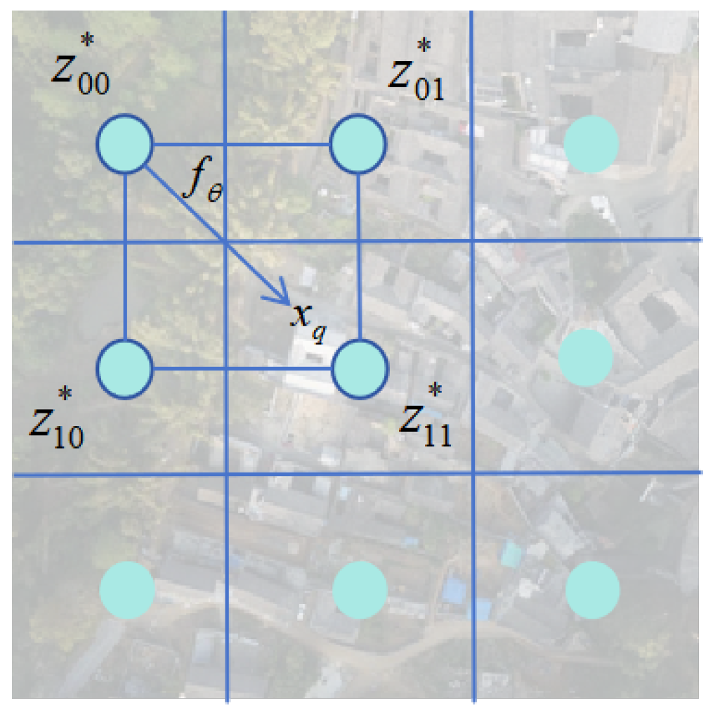
The pixel-based representation of LIIF is plotted in Figure 7. In this figure, represents the central coordinates of the pixel to be queried, and is the obtained RGB value from the query. Due to the different aspect ratios between stitched images and the diffusion model, directly resizing stitched images may cause stretching and deformation. To avoid this problem, before adjusting the image size, padding is applied to adjust the ratio of the length and width of the stitched images to match the trained diffusion model, which is
The padded image is then used to calculate the central coordinates of each pixel with a scaling factor . LIIF is employed for querying to achieve adjustment to match the size of the diffusion model. For the results after restoration through the diffusion model, the size is similarly restored using LIIF, and the padded areas are cropped to obtain the restored image.
4. Experiment
4.1. Data Preparation
We conducted on-site aerial photography using a UAV, capturing a total of 1008 images at a resolution of 6000 × 4000 pixels. From these, 48 images were set aside as a validation set denoted as dataset 3. Each set of 6 images within this validation set was designated as a stitching object, resulting in a total of 8 groups. Due to the significant difference in data dimensions compared to the diffusion model, we downsampled the images to a resolution of 480 × 320 pixels. The remaining 960 images were cropped into squares, downsampled to 256 × 256 pixels, and subjected to random flips or exchanges, resulting in 1920 images to form the training dataset denoted as dataset 1 for the diffusion model. The original high-resolution dataset denoted as dataset 2 was utilized as the training dataset for the Learning-based Inpainting with Fourier Features (LIIF) model.
4.2. Model Training Details
4.2.1. Diffusion Model Training
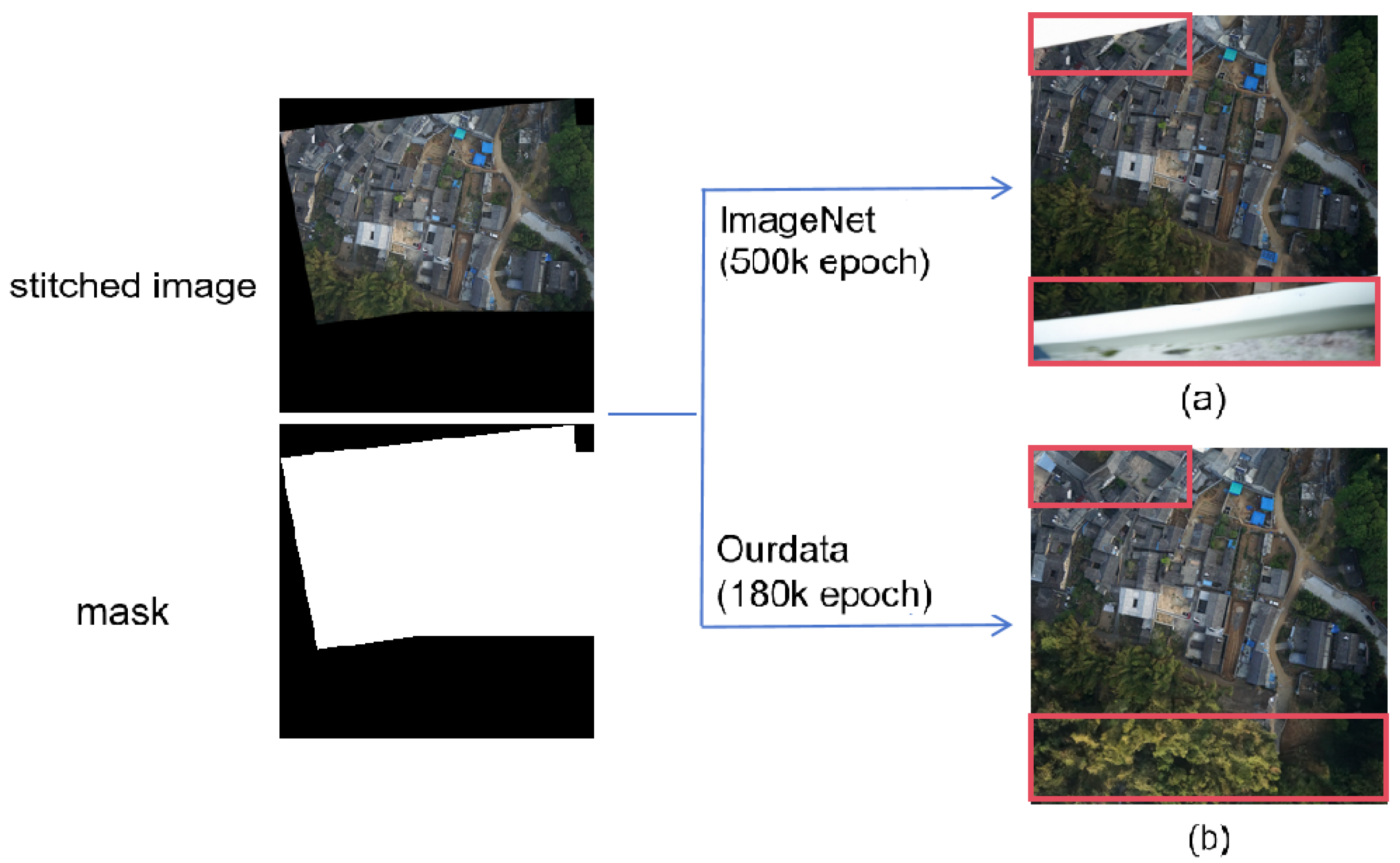
The network model used in this paper is a U-Net model with temporal injection, as shown in Figure 8. The backbone network is a residual network with attention layers. To enable the model to learn sufficient details for image restoration, we set the channels of the residual block to 256. Within the same-scale module of the U-Net, the number of residual blocks was set to 2, and the number of heads in the attention module was set to 64. This paper compares the restoration results of two models trained on ImageNet 256 × 256 and our dataset 1 of UAV images, respectively. The goal is to investigate the generalization and fitting of the models in the restoration task. We conducted training on an NVIDIA RTX 3090 GPU (Santa Clara, CA, USA) with a batch size of 1. As shown in Figure 9, the model trained on the ImageNet dataset for 500k epochs occasionally produced counterintuitive images when the mask proportion was high. In contrast, the model trained solely on our dataset 1 for 180k epochs demonstrated excellent inference capabilities, consistently generating high-quality images.
4.2.2. LIIF Training
This part compares the performance of a pre-trained model [29] with a model fine-tuned with our dataset. Although using this pre-trained model for image size adjustment directly has shown significant improvement when compared with direct interpolation methods, some features such as the direction of roof tiles are still over smoothed. We fine-tuned the pre-trained model with our dataset (dataset 2) and compared the final results with the pre-trained model. One can observe that, at the adjustment of ×23 in image size for downsampling and upsampling, using the pre-trained model directly leads to the loss of many texture details. After fine-tuning the pre-trained model with our dataset, the model exhibits richer texture details, as shown in Figure 10. If only at a smaller scale adjustment, such as 2.3×, the difference in image details is difficult to observe when compared with the ground truth, as shown in Figure 11.
4.3. UAV Image Stitching Results and Analysis
4.3.1. Overall Results Comparison
We evaluated the performance of many stitching and restoration methods using the UAV images taken from dataset 3. The proposed method was compared with AANAP [36], UDIS++ [31], and Deep Rectangling [30]. The comparison results are shown in Figure 12. From this figure, it is obvious that the proposed method performs better than the competing methods in terms of both image completeness and transition smoothness.
4.3.2. Seam Repairment Details
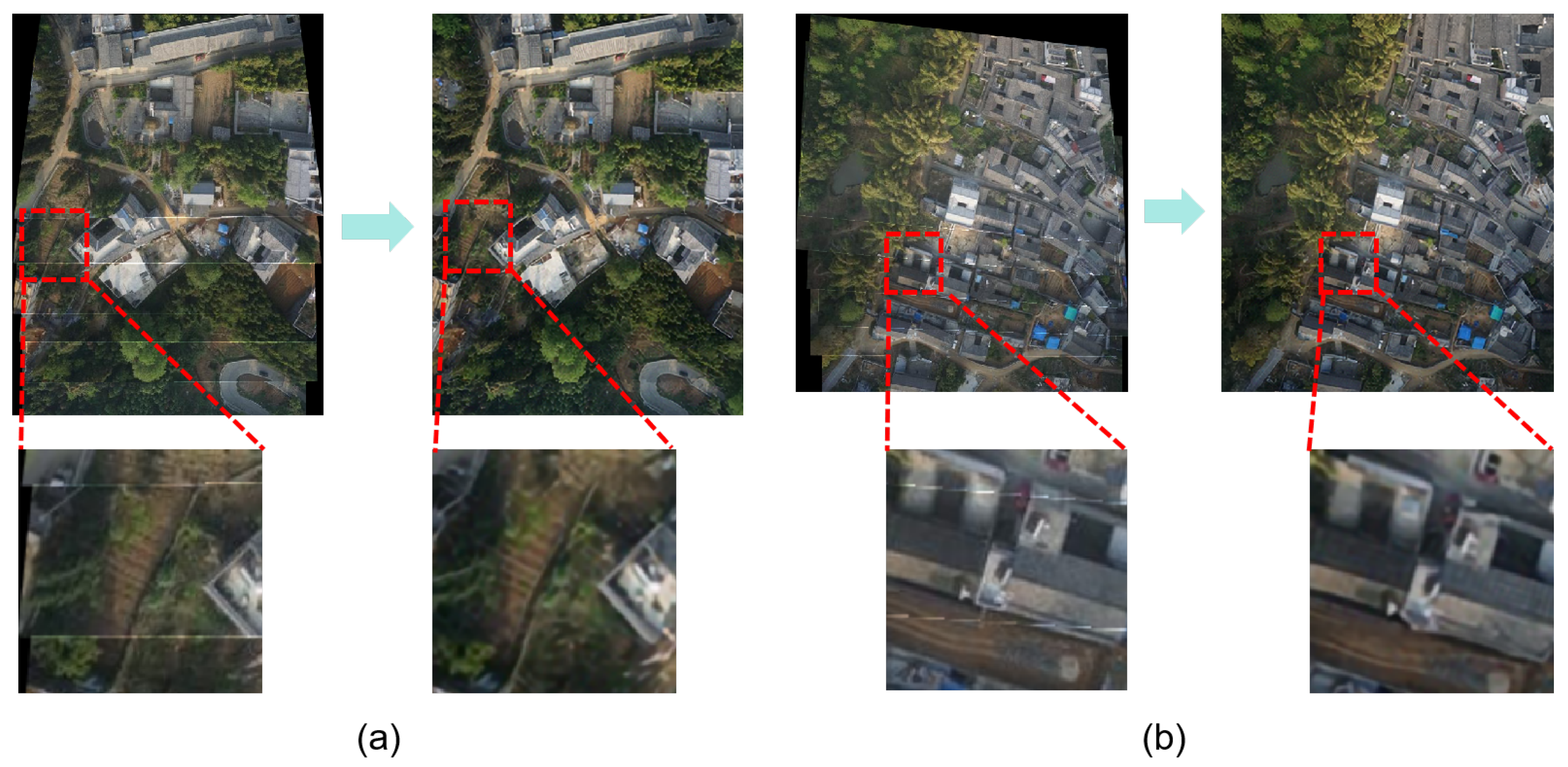
We compared the repairment details at the image seams in our results, as shown in Figure 13. It can be observed that, although high-quality repairment results were achieved, some small textures at the seams were altered.
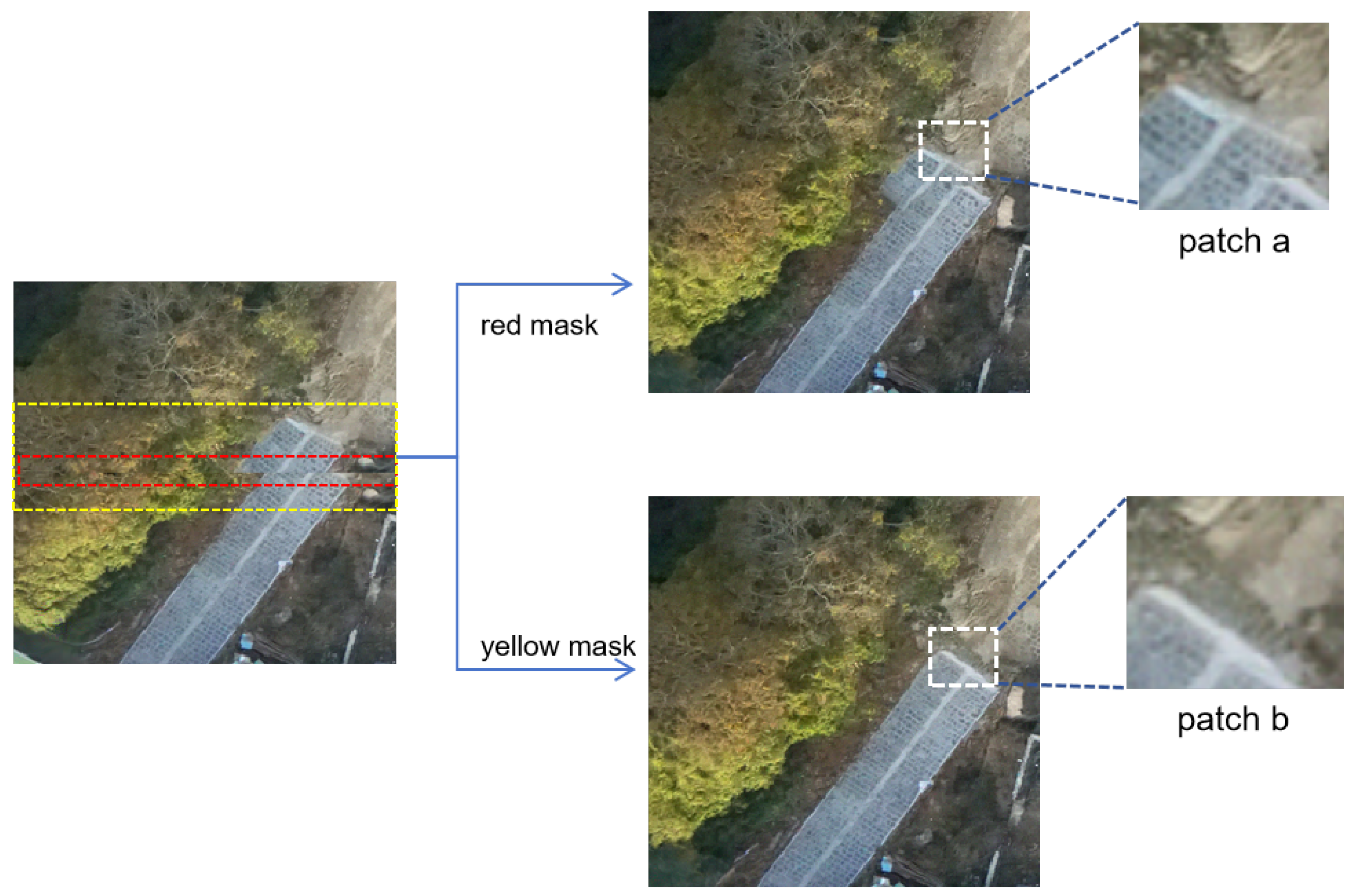
Furthermore, we compared the results of repairing seams with different widths of masks for the same degree of misalignment as shown in Figure 14. We can observe that when using the red mask, which cannot completely cover the misaligned area, the repairment result is relatively poor. On the other hand, when using the yellow mask, which can entirely cover the entire misaligned area, the repairment effect is promising but comes with the trade-off of accepting some changes in fine textures within the masked region when compared with the ground truth. Through experiments conducted on the training dataset as the preliminary experiments, we found that setting the mask width to be between 1/60 and 1/80 of the total pixels can achieve a balanced performance. For practical applications, adjustments can be made based on the actual displacement at the seams, which is out of the scope of this paper.
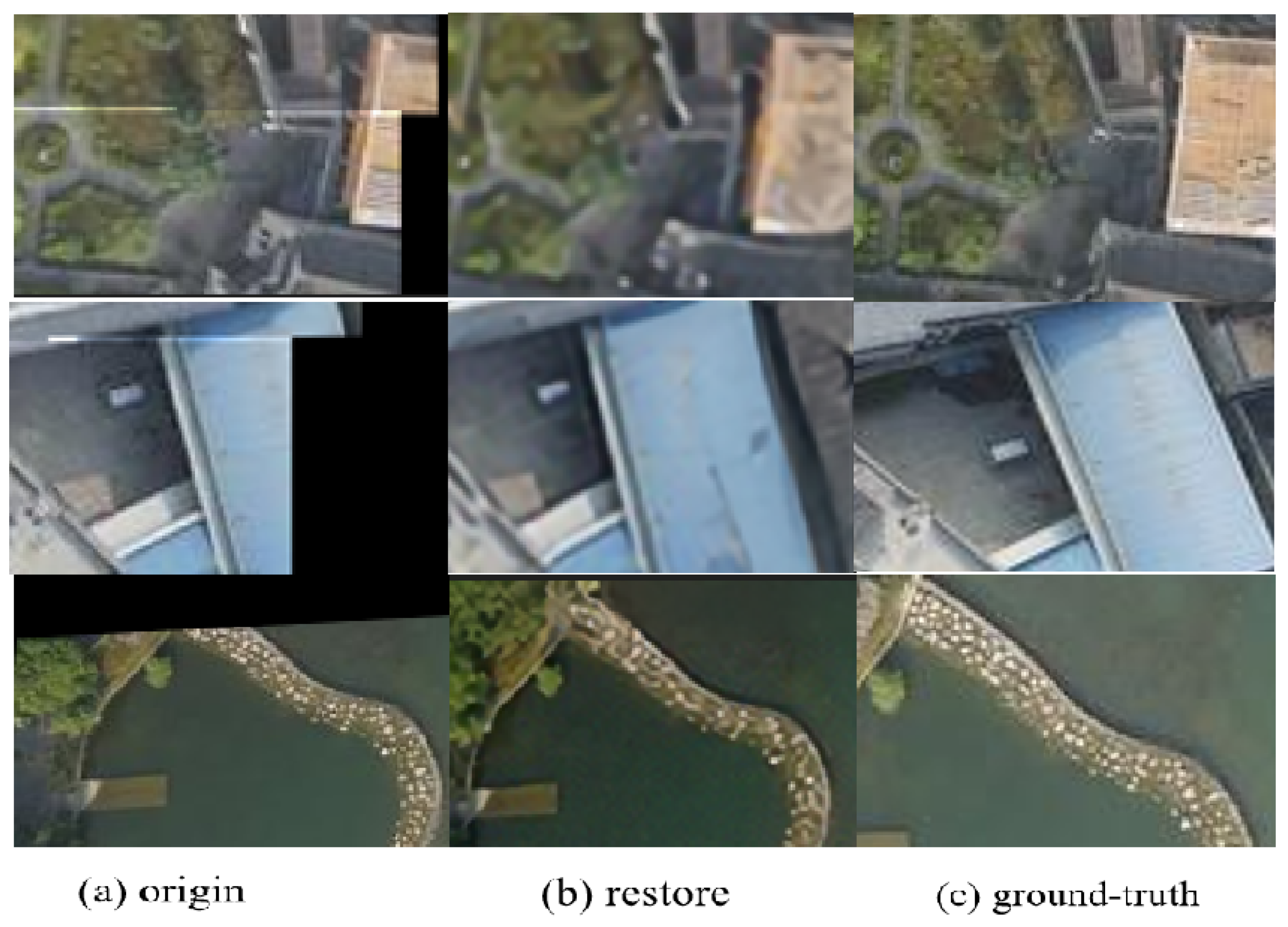
For the repairment of irregular boundaries, we captured additional images from a perspective roughly similar to the stitched result. We identified corresponding content for some irregular boundaries in these images and used them as ground truth for comparison with our repair results. The repair outcomes exhibit a consistent alignment with the ground truth in terms of both texture extension and semantics, as depicted in Figure 15.
4.4. Quantitative Evaluation
Due to the difficulty in obtaining globally accurate reference values for the repaired images, we manually selected image patches as the ground truth for comparison with the results before and after restoration. This allows us to assess the overall quality of the images. In this study, we used the SSIM and PSNR metrics to compare the similarity between the images before and after restoration and the reference values. We manually selected image regions from the stitched images as reference values and calculated the average similarity scores before and after restoration using the above-mentioned metrics. The results are presented in Table 1. The similarity scores after restoration showed a significant improvement, attributed to the high level of agreement between the repaired generated images and the reference values in terms of texture and semantics.
Due to the limited comparison conducted in certain regions of the images and the absence of the global ground-truth reference, we further compared the quality of the images in an intuitive way. Our results repaired the texture at seams, making transitions smooth, and eliminated large irregular boundaries. However, due to the upsampling and downsampling during the restoration process, resolution could be decreased, which adversely affects the evaluation of our restored results. We further employed a non-intrusive perceptual image quality assessment tool, e.g., PaQ-2-PiQ [37], to solve the problem of the absence of the global ground-truth reference. It should be mentioned that PaQ-2-PiQ utilizes a large subjective quality database for training and can infer globally to locally and locally to globally, and it focuses more on the overall subjective perception of images rather than just sharpness. It also provides more consistent evaluation results with human perception, especially for “more blurred but more visually pleasing” images. When using PaQ-2-PiQ to evaluate different methods, the proposed method was compared with UDIS++, AANAP, and Deep Rectangling. The PaQ-2-PiQ scores are summarized in Table 2. The quantitative results double confirm that the proposed method outperforms many existing SOTA methods in terms of perceptual quality, which is consistent with the visual results presented in Figure 12. For methods that require multiple stitching operations, such as AANAP and UDIS++, numerous cumulative errors might be inevitably introduced during repeating the stitching process several times, resulting in their scores being even lower than the original stitched results.
4.5. Ablation Studies
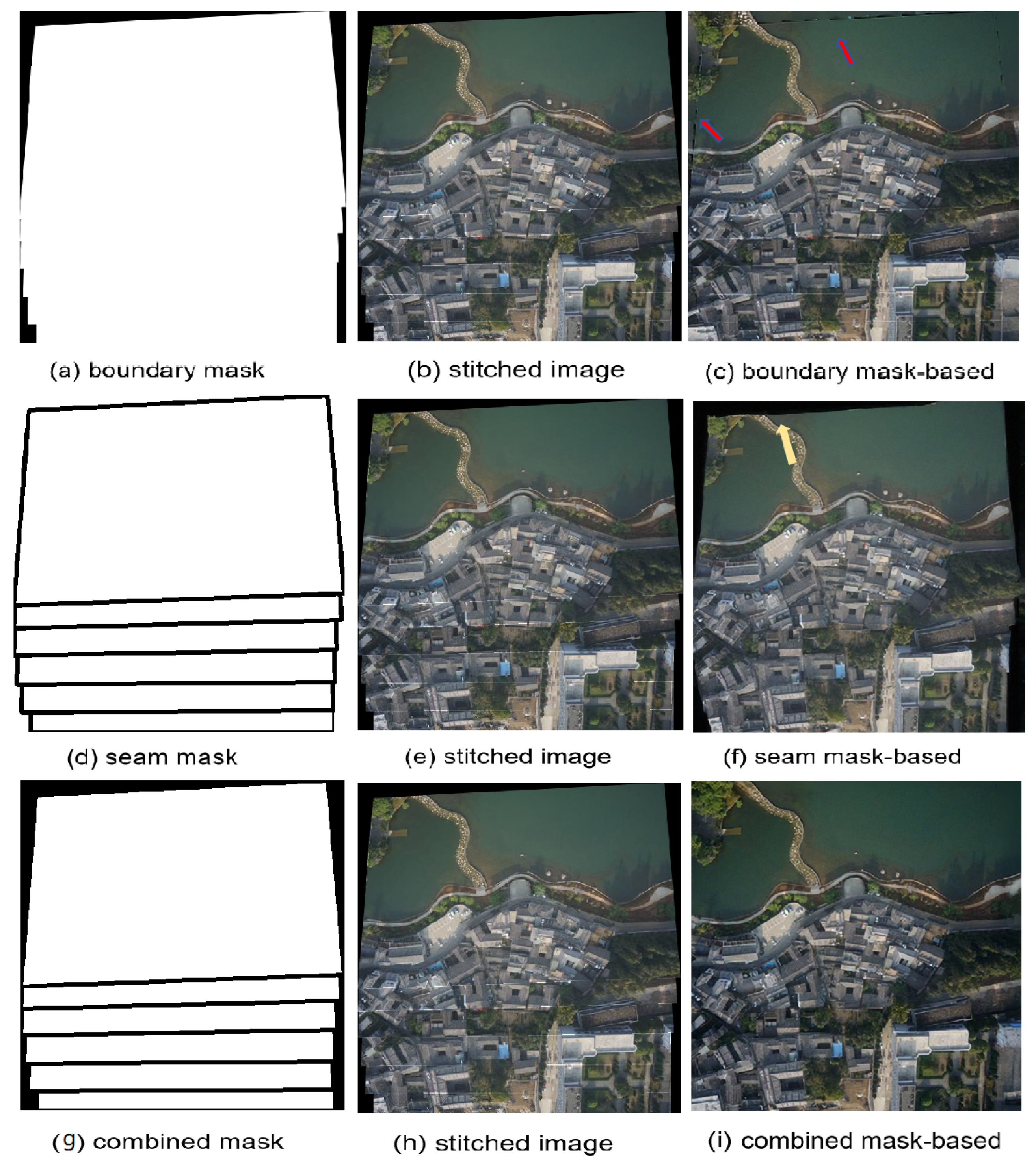
To demonstrate the effectiveness of using the combined mask including the boundary and seam masks, we compared the three restoration results: using only the irregular boundary mask, only the seam mask, and the two masks combined.
Boundary Mask. If masks are only computed for dealing with irregular boundaries, the proposed method can only be expected to reduce the irregular boundaries, while the seams cannot be solved. In this case, there might be unnatural transitions at the junctions between irregular boundaries and image edges, as indicated by the arrows in Figure 16a–c.
Seam mask. If masks are computed only for seams, the proposed method can only be expected to reduce the seams, while it is unable to achieve promising results with a rectangular field of view, and nonlinear distortion still occurs at the edges of irregular boundaries as shown in Figure 16d–f.
When using the combination of the boundary and seam masks, it is expected that the proposed method can reduce both the irregualr boundaries and seams. This is the case that can be seen from Figure 16g–i. From Figure 16, we can conclude that if we separately compute masks for irregular boundaries and seams, unnatural transitions and nonlinear distortions often occur at some edges of the image. Moreover, if we repair the remaining parts continuously, the masks calculated earlier cannot accurately correspond to the repaired results.
5. Conclusions
We addressed the irregular boundaries and stitching seams for the UAV image stitching task by devising a method to generate masks during image stitching, and a processing framework based on the diffusion model was developed, in which the unconditional score function of the diffusion model is ultilized during the inverse process. We also applied additional manifold gradient constraints to repair masked images, aiming to eliminate irregular boundaries and stitching seams, resulting in improved perceptual quality.
Unlike those often-used methods based on grids or energy minimization functions, our proposed method is data-driven, considering the overall distribution of pixels. It does not strictly require specific geometric structures or texture features near irregular boundaries and stitching seams. Therefore, even in challenging scenarios with complex shapes of irregular boundaries, multiple seams, and insufficient geometric and texture features, our proposed method can still achieve high-quality results. Moreover, due to the powerful learning and inference capabilities of the diffusion model for data distribution, training on a small dataset of UAV images can obtain a high-quality model for the restoration of stitched images, facilitating its potential applications.
Note that our proposed method may introduce some perceptually acceptable but “unrealistic” or artificial noise locally into the mask. In scenarios where strict authenticity requirements for data are essential, such as in ultra-high-resolution map drawing, introducing small unrealistic/artificial noise may be intolerable. Yet, for scenarios with a higher tolerance for realism, such as VR/AR applications, our proposed method may provide an alternative way to improve the quality of the stitched images. Evaluating and quantifying the introduced unrealistic noise as well as determining its acceptability still lack quantitative analysis tools. Future research can focus on how to quantitatively evaluate these introduced unrealistic noise components and solve this problem in an efficient way.
Author Contributions
Conceptualization, J.C., J.W., J.L. and Y.L.; methodology, J.C. and Y.L.; software, Y.L., H.T. and J.C.; validation, Y.L.; formal analysis, J.C. and Y.L.; investigation, Y.L. and J.C.; resources, J.C.; data curation, J.C.; writing—original draft preparation, Y.L. and J.C.; writing—review and editing, J.C. and Y.L.; funding acquisition, Y.T. and J.C. All authors have read and agreed to the published version of the manuscript.
Funding
This research was funded by The National Natural Science Foundation of China (Grant No. 42327801).
Data Availability Statement
The data presented in this study are available on request from the corresponding author. The data are not publicly available due to privacy restrictions. Our trained model can be accessed from the following page: https://huggingface.co/xhehe/uav_diffusion/tree/main, accessed on 24 March 2024.
Conflicts of Interest
The authors declare no conflicts of interest.
Abbreviations
The following abbreviations are used in this manuscript:
| LIIF | Local Implicit Image Function |
| DDPM | Denoising Diffusion Probabilistic Models |
| HNSW | Hierarchical Navigable Small World |
| SIFT | Scale-Invariant Feature Transform |
| UAV | Unmanned Aerial Vehicle |
| GAN | Generative Adversarial Network |
References
- Gómez-Reyes, J.K.; Benítez-Rangel, J.P.; Morales-Hernández, L.A.; Resendiz-Ochoa, E.; Camarillo-Gomez, K.A. Image mosaicing applied on UAVs survey. Appl. Sci. 2022, 12, 2729. [Google Scholar] [CrossRef]
- Chen, Y.S.; Chuang, Y.Y. Natural image stitching with the global similarity prior. In Proceedings of the European Conference on Computer Vision, Amsterdam, The Netherlands, 11–14 October 2016; pp. 186–201. [Google Scholar]
- Lee, K.Y.; Sim, J.Y. Warping residual based image stitching for large parallax. In Proceedings of the IEEE/CVF Conference on Computer Vision and Pattern Recognition, Seattle, WA, USA, 13–19 June 2020; pp. 8198–8206. [Google Scholar]
- Lin, W.Y.; Liu, S.; Matsushita, Y.; Ng, T.T.; Cheong, L.F. Smoothly varying affine stitching. In Proceedings of the CVPR 2011, Colorado Springs, CO, USA, 20–25 June 2011; pp. 345–352. [Google Scholar]
- Zaragoza, J.; Chin, T.J.; Brown, M.S.; Suter, D. As-projective-as-possible image stitching with moving DLT. In Proceedings of the IEEE Conference on Computer Vision and Pattern Recognition, Portland, OR, USA, 23–28 June 2013; pp. 2339–2346. [Google Scholar]
- Guo, D.; Chen, J.; Luo, L.; Gong, W.; Wei, L. UAV image stitching using shape-preserving warp combined with global alignment. IEEE Geosci. Remote Sens. Lett. 2022, 19, 8016005. [Google Scholar] [CrossRef]
- Cui, Z.; Tang, R.; Wei, J. UAV image stitching with Transformer and small grid reformation. IEEE Geosci. Remote Sens. Lett. 2023, 20, 5001305. [Google Scholar] [CrossRef]
- He, L.; Li, X.; He, X.; Li, J.; Song, S.; Plaza, A. VSP-Based Warping for Stitching Many UAV Images. IEEE Trans. Geosci. Remote Sens. 2023, 61, 5624717. [Google Scholar] [CrossRef]
- He, K.; Chang, H.; Sun, J. Rectangling panoramic images via warping. ACM Trans. Graph. 2013, 32, 1–10. [Google Scholar] [CrossRef]
- Li, D.; He, K.; Sun, J.; Zhou, K. A geodesic-preserving method for image warping. In Proceedings of the IEEE Conference on Computer Vision and Pattern Recognition, Boston, MA, USA, 7–12 June 2015; pp. 213–221. [Google Scholar]
- Zhang, Y.; Lai, Y.K.; Zhang, F.L. Content-preserving image stitching with piecewise rectangular boundary constraints. IEEE Trans. Vis. Comput. Graph. 2020, 27, 3198–3212. [Google Scholar] [CrossRef] [PubMed]
- Kwatra, V.; Schödl, A.; Essa, I.; Turk, G.; Bobick, A. Graphcut textures: Image and video synthesis using graph cuts. ACM Trans. Graph. 2003, 22, 277–286. [Google Scholar] [CrossRef]
- Li, N.; Liao, T.; Wang, C. Perception-based seam cutting for image stitching. Signal Image Video Process. 2018, 12, 967–974. [Google Scholar] [CrossRef]
- Chen, X.; Yu, M.; Song, Y. Optimized seam-driven image stitching method based on scene depth information. Electronics 2022, 11, 1876. [Google Scholar] [CrossRef]
- Agarwala, A.; Dontcheva, M.; Agrawala, M.; Drucker, S.; Colburn, A.; Curless, B.; Salesin, D.; Cohen, M. Interactive digital photomontage. In ACM SIGGRAPH 2004 Papers; Association for Computing Machinery: New York, NY, USA, 2004; pp. 294–302. [Google Scholar]
- Dai, Q.; Fang, F.; Li, J.; Zhang, G.; Zhou, A. Edge-guided composition network for image stitching. Pattern Recognit. 2021, 118, 108019. [Google Scholar] [CrossRef]
- Eden, A.; Uyttendaele, M.; Szeliski, R. Seamless image stitching of scenes with large motions and exposure differences. In Proceedings of the 2006 IEEE Computer Society Conference on Computer Vision and Pattern Recognition (CVPR’06), New York, NY, USA, 7–22 June 2006; Volume 2, pp. 2498–2505. [Google Scholar]
- Lin, K.; Jiang, N.; Cheong, L.F.; Do, M.; Lu, J. Seagull: Seam-guided local alignment for parallax-tolerant image stitching. In Proceedings of the Computer Vision–ECCV 2016: 14th European Conference, Amsterdam, The Netherlands, 11–14 October 2016; pp. 370–385. [Google Scholar]
- Gao, J.; Li, Y.; Chin, T.J.; Brown, M.S. Seam-driven image stitching. In Proceedings of the Eurographics, Girona, Spain, 6–10 May 2013; pp. 45–48. [Google Scholar]
- Zhang, F.; Liu, F. Parallax-tolerant image stitching. In Proceedings of the IEEE Conference on Computer Vision and Pattern Recognition, Columbus, OH, USA, 23–28 June 2014; pp. 3262–3269. [Google Scholar]
- Li, J.; Zhou, Y. Automatic color image stitching using quaternion rank-1 alignment. In Proceedings of the IEEE/CVF Conference on Computer Vision and Pattern Recognition, New Orleans, LA, USA, 8–24 June 2022; pp. 19720–19729. [Google Scholar]
- Sohl-Dickstein, J.; Weiss, E.; Maheswaranathan, N.; Ganguli, S. Deep unsupervised learning using nonequilibrium thermodynamics. In Proceedings of the International Conference on Machine Learning, Lille, France, 6–11 July 2015; pp. 2256–2265. [Google Scholar]
- Ho, J.; Jain, A.; Abbeel, P. Denoising diffusion probabilistic models. Adv. Neural Inf. Process. Syst. 2020, 33, 6840–6851. [Google Scholar]
- Nichol, A.Q.; Dhariwal, P. Improved denoising diffusion probabilistic models. In Proceedings of the International Conference on Machine Learning, Virtual, 18–24 July 2021; pp. 8162–8171. [Google Scholar]
- Dhariwal, P.; Nichol, A. Diffusion models beat gans on image synthesis. Adv. Neural Inf. Process. Syst. 2021, 34, 8780–8794. [Google Scholar]
- Zhu, Y.; Zhang, K.; Liang, J.; Cao, J.; Wen, B.; Timofte, R.; Van Gool, L. Denoising Diffusion Models for Plug-and-Play Image Restoration. In Proceedings of the IEEE/CVF Conference on Computer Vision and Pattern Recognition, Vancouver, BC, Canada, 17–24 June 2023; pp. 1219–1229. [Google Scholar]
- Kawar, B.; Elad, M.; Ermon, S.; Song, J. Denoising diffusion restoration models. Adv. Neural Inf. Process. Syst. 2022, 35, 23593–23606. [Google Scholar]
- Chung, H.; Sim, B.; Ryu, D.; Ye, J.C. Improving diffusion models for inverse problems using manifold constraints. Adv. Neural Inf. Process. Syst. 2022, 35, 25683–25696. [Google Scholar]
- Chen, Y.; Liu, S.; Wang, X. Learning continuous image representation with local implicit image function. In Proceedings of the IEEE/CVF Conference on Computer Vision and Pattern Recognition, Nashville, TN, USA, 20–25 June 2021; pp. 8628–8638. [Google Scholar]
- Nie, L.; Lin, C.; Liao, K.; Liu, S.; Zhao, Y. Deep rectangling for image stitching: A learning baseline. In Proceedings of the IEEE/CVF Conference on Computer Vision and Pattern Recognition, New Orleans, LA, USA, 8–24 June 2022; pp. 5740–5748. [Google Scholar]
- Nie, L.; Lin, C.; Liao, K.; Liu, S.; Zhao, Y. Parallax-tolerant unsupervised deep image stitching. In Proceedings of the IEEE/CVF International Conference on Computer Vision, Paris, France, 2–6 October 2023; pp. 7399–7408. [Google Scholar]
- Ng, P.C.; Henikoff, S. SIFT: Predicting amino acid changes that affect protein function. Nucleic Acids Res. 2003, 31, 3812–3814. [Google Scholar] [CrossRef] [PubMed]
- Malkov, Y.A.; Yashunin, D.A. Efficient and robust approximate nearest neighbor search using hierarchical navigable small world graphs. IEEE Trans. Pattern Anal. Mach. Intell. 2018, 42, 824–836. [Google Scholar] [CrossRef] [PubMed]
- Song, Y.; Sohl-Dickstein, J.; Kingma, D.P.; Kumar, A.; Ermon, S.; Poole, B. Score-based generative modeling through stochastic differential equations. arXiv 2020, arXiv:2011.13456. [Google Scholar]
- Kadkhodaie, Z.; Simoncelli, E. Stochastic solutions for linear inverse problems using the prior implicit in a denoiser. Adv. Neural Inf. Process. Syst. 2021, 34, 13242–13254. [Google Scholar]
- Lin, C.C.; Pankanti, S.U.; Natesan Ramamurthy, K.; Aravkin, A.Y. Adaptive as-natural-as-possible image stitching. In Proceedings of the IEEE Conference on Computer Vision and Pattern Recognition, Boston, MA, USA, 7–12 June 2015; pp. 1155–1163. [Google Scholar]
- Ying, Z.; Niu, H.; Gupta, P.; Mahajan, D.; Ghadiyaram, D.; Bovik, A. From patches to pictures (PaQ-2-PiQ): Mapping the perceptual space of picture quality. In Proceedings of the IEEE/CVF Conference on Computer Vision and Pattern Recognition, Seattle, WA, USA, 13–19 June 2020; pp. 3575–3585. [Google Scholar]
Figure 1.
Irregular boundaries and stitching seams are present in the stitched images of the unmanned aerial vehicle. In the (a,b) results, the areas enclosed by the red and yellow boxes, respectively, represent portions of stitching seams and irregular boundaries.
Figure 1.
Irregular boundaries and stitching seams are present in the stitched images of the unmanned aerial vehicle. In the (a,b) results, the areas enclosed by the red and yellow boxes, respectively, represent portions of stitching seams and irregular boundaries.

Figure 2.
Comparison of different solutions: (a) Raw stitched image; (b) Nie et al.’s retangling [30]: most areas are rectangularized, but this method cannot completely eliminate irregular boundaries; (c) Nie et al.’s UDIS++ [31]: this method can achieve perfect transitions at seams but exhibits large irregular boundaries; (d) our method: the proposed method provides perfect transitions at seams and completely eliminates irregular boundaries.

Figure 3.
The overall diagram of the proposed method. The framework consists of two stages: stitching and restoration. In the stitching stage, the boundary and seam masks for each stitched image are also computed. In the restoration stage, the inverse process of the pre-trained diffusion model is used to restore the raw stitched image with the help of the masks computed in the stitching stage.

Figure 4.
Stitching process. The first UAV image is used to initialize input 1, and the remaining UAV images to are used in order as input 2. After stitching the two images, i.e., input 1 and input 2, there are two ouputs: One is output 1 indicating the stitched image, and the other output is the masks. Ouput 1 is repeatedly used as input 1 until all UAV images are used in the image stitching stage. Accordingly, the final output consists of the stitched image and the masks for irregular boundaries and seams.

Figure 5.
The inverse process of the diffusion model for restoration: ① The initial sampling of inverse diffusion; ② performing inverse iteration using the manifold gradient constraint; ③ taking the orthogonal complement with the mask; ④ sampling from and adding to the orthogonal complement.
Figure 5.
The inverse process of the diffusion model for restoration: ① The initial sampling of inverse diffusion; ② performing inverse iteration using the manifold gradient constraint; ③ taking the orthogonal complement with the mask; ④ sampling from and adding to the orthogonal complement.

Figure 6.
LIIF representation with local ensemble.

Figure 7.
Pixel-based representation of LIIF.

Figure 8.
U-Net model with time injection. Each layer of the U-Net consists of a ResNet with different sizes.
Figure 8.
U-Net model with time injection. Each layer of the U-Net consists of a ResNet with different sizes.

Figure 9.
Comparison of the model trained on ImageNet and that trained on dataset 1 in terms of perceptual quality: (a) model trained on ImageNet with two patching errors (red boxes); (b) model trained on dataset 1.
Figure 9.
Comparison of the model trained on ImageNet and that trained on dataset 1 in terms of perceptual quality: (a) model trained on ImageNet with two patching errors (red boxes); (b) model trained on dataset 1.

Figure 10.
Comparison of the details of LIIF after data augmentation under large-scale adjustment. (a) Ground truth data; (b) details of the image at 23.4× downsampling and upsampling using the pre-trained model; (c) details of the image at 23.4× downsampling and upsampling using the fine-tuned model.

Figure 11.
Comparison of the details under small-scale adjustments after model enhancement. (a) Ground truth data, (b) details of downsampling and upsampling by ×2.3 with the enhanced model.
Figure 11.
Comparison of the details under small-scale adjustments after model enhancement. (a) Ground truth data, (b) details of downsampling and upsampling by ×2.3 with the enhanced model.

Figure 12.
Comparison of the final results from different methods.

Figure 13.
Comparison of seam repairment details with and without the proposed seam repairment method. (a) The first example, (b) the second example. The images with and without the proposed method for each example are placed on the left and right parts, repsectively.
Figure 13.
Comparison of seam repairment details with and without the proposed seam repairment method. (a) The first example, (b) the second example. The images with and without the proposed method for each example are placed on the left and right parts, repsectively.

Figure 14.
Comparison of the repair effects of different width masks on the same seam. (patch a) Solving the seam with the red mask, the transition is natural, but misalignment still exists. (patch b) Solving the seam with the yellow mask, misalignment and seam repair are good, but it may introduce unrealistic changes.

Figure 15.
Comparison between repaired values and ground truth for irregular boundaries.

Figure 16.
The ablation study using different masks. (a–c) show the importance of using boundary masks; (d–f) show the importance of using seam masks; (g–i) show the importance of using both boundary and seam masks.
Figure 16.
The ablation study using different masks. (a–c) show the importance of using boundary masks; (d–f) show the importance of using seam masks; (g–i) show the importance of using both boundary and seam masks.


Table 1.
Measurement of similarity between images with and without the proposed restoration method and the reference image.
Table 1.
Measurement of similarity between images with and without the proposed restoration method and the reference image.
| Method | SSIM↑ | PSNR↑ |
|---|---|---|
| Origin | 0.361 | 12.724 |
| Restore | 0.434 | 17.011 |
Table 2.
Comparison of PaQ-2-PiQ before and after restoration.
| Method | PaQ-2-PiQ↑ |
|---|---|
| Stitched image | 0.741 |
| AANAP | 0.684 |
| UDIS++ | 0.734 |
| Deep Rectangling | 0.743 |
| Ours | 0.766 |
Disclaimer/Publisher’s Note: The statements, opinions and data contained in all publications are solely those of the individual author(s) and contributor(s) and not of MDPI and/or the editor(s). MDPI and/or the editor(s) disclaim responsibility for any injury to people or property resulting from any ideas, methods, instructions or products referred to in the content. |
© 2024 by the authors. Licensee MDPI, Basel, Switzerland. This article is an open access article distributed under the terms and conditions of the Creative Commons Attribution (CC BY) license (https://creativecommons.org/licenses/by/4.0/).
Share and Cite
MDPI and ACS Style
Chen, J.; Luo, Y.; Wang, J.; Tang, H.; Tang, Y.; Li, J. Elimination of Irregular Boundaries and Seams for UAV Image Stitching with a Diffusion Model. Remote Sens. 2024, 16, 1483. https://doi.org/10.3390/rs16091483
AMA Style
Chen J, Luo Y, Wang J, Tang H, Tang Y, Li J. Elimination of Irregular Boundaries and Seams for UAV Image Stitching with a Diffusion Model. Remote Sensing. 2024; 16(9):1483. https://doi.org/10.3390/rs16091483
Chicago/Turabian StyleChen, Jun, Yongxi Luo, Jie Wang, Honghua Tang, Yixian Tang, and Jianhui Li. 2024. "Elimination of Irregular Boundaries and Seams for UAV Image Stitching with a Diffusion Model" Remote Sensing 16, no. 9: 1483. https://doi.org/10.3390/rs16091483
Note that from the first issue of 2016, this journal uses article numbers instead of page numbers. See further details here.