Article

Live Coral Cover Index Testing and Application with Hyperspectral Airborne Image Data

by
Karen E. Joyce
1,2,*,
Stuart R. Phinn
2 and
Chris M. Roelfsema
2
1
Research Institute for the Environment and Livelihoods, Charles Darwin University, Casuarina Campus, Darwin, NT 0810, Australia
2
Centre for Spatial Environmental Research, School of Geography, Planning, and Environmental Management, University of Queensland, St Lucia, QLD 4072, Australia
*
Author to whom correspondence should be addressed.
Remote Sens. 2013, 5(11), 6116-6137; https://doi.org/10.3390/rs5116116
Submission received: 8 October 2013 / Revised: 13 November 2013 / Accepted: 18 November 2013 / Published: 20 November 2013

Abstract

:
Coral reefs are complex, heterogeneous environments where it is common for the features of interest to be smaller than the spatial dimensions of imaging sensors. While the coverage of live coral at any point in time is a critical environmental management issue, image pixels may represent mixed proportions of coverage. In order to address this, we describe the development, application, and testing of a spectral index for mapping live coral cover using CASI-2 airborne hyperspectral high spatial resolution imagery of Heron Reef, Australia. Field surveys were conducted in areas of varying depth to quantify live coral cover. Image statistics were extracted from co-registered imagery in the form of reflectance, derivatives, and band ratios. Each of the spectral transforms was assessed for their correlation with live coral cover, determining that the second derivative around 564 nm was the most sensitive to live coral cover variations(r2 = 0.63). Extensive field survey was used to transform relative to absolute coral cover, which was then applied to produce a live coral cover map of Heron Reef. We present the live coral cover index as a simple and viable means to estimate the amount of live coral over potentially thousands of km2 and in clear-water reefs.

Graphical Abstract

1. Introduction

1.1. Spectral Mixing Challenges in Coral Reef Remote Sensing

Coral reef remote sensing has been a topic of research and application since the late 1970s. The field has expanded from the development of aerial photo interpretation cues such as pattern, texture and tone for habitat classifications [1] to the incorporation of satellite data through the initial testing of Landsat MSS/TM and SPOT data for geomorphic or broad habitat classifications [26]. As high spatial resolution imagery has become increasing available, it has become possible to move beyond the classification of broad geomorphic zones through to identifying coral colonies and providing details of coral structure to a much greater detail [713], and employing object based image analysis techniques [1416]. However, the majority of these mapping applications deliver a categorical classification product, which does not address the inherent spatial heterogeneity in coral reef environments and the image pixels by which they are represented.
The scales of heterogeneity in benthic feature types on coral reefs are such that the spatial dimensions of most contemporary remote sensing systems will result in a pixel size that is greater than the feature of interest (L-resolution). Spectral mixing at the pixel scale has been identified in the past and continues to be a significant challenge in coral reef mapping [1723]. To address this, Hochberg and Atkinson [17] assessed the theoretical limits of currently available remote sensing systems to classify coral, algae and sediment mixed spectra through simulations based on field spectrometry data. Similarly, Hedley, Mumby [20] conducted an ex situ experiment to collect and analyze the combined spectra of up to three different benthic types within a single field of view using a field spectrometer. Both studies assumed simple linear mixing and achieved successful results with hyperspectral data in the absence of water column and atmospheric attenuation.
In the image domain, Goodman and Ustin [21] present a refinement and test case of the algorithm developed by Lee, Carder [24] to retrieve bottom albedo and water depth using AVIRIS hyperspectral data over Kaneohe Bay, Hawai’i. This technique produced promising results for bathymetry, water column properties and relative cover of coral, algae and sand. Hedley and Mumby [19] document a similar output by modifying spectral unmixing to estimate depth as well as extract benthic type. This method has worked well on simulated data but requires knowledge of the diffuse attenuation coefficient of the water body at the site. Most recently, Hamylton [22] has had success using linear unmixing to map four different benthic feature types, in addition to depth, using a combination of derivative and raw hyperspectral spectra as well as extensive field survey for calibration and validation. Thus, it can be seen that in its early testing phases, spectral unmixing in coral reef environments is proving to be a valid approach for mapping at the L-resolution scale, though is disadvantaged by the need to define all benthic types or “endmembers” within an image, including the inherent optical properties of the water column, and still requires a large number of spectral bands to be effective.

1.2. Spectral Indices and Coral Reef Mapping Potential

Spectral unmixing is not the only approach available to account for environmental heterogeneity within an image. Spectral indices were also developed in part to address this heterogeneity and the shortfalls of mapping with per-pixel categorical classifications. Indices have been used extensively in terrestrial and oceanic environments to provide biophysical information such as vegetation cover [25], leaf area index [26], and ocean color [27]. These image transforms present a simpler method of retrieving information about the relative coverage of target features, and can be implemented rapidly and with little user expertise [28]. In addition, they output a dataset corresponding to a continuous variable able to be linked to a biophysical variable (e.g., leaf area index or chlorophyll content) rather than a thematic map, which assumes a discontinuous distribution at the scale of image pixels.
The development of spectral indices for benthic habitat mapping in submerged environments is in its infancy. Mumby [29] used satellite multispectral (SPOT XS and Landsat TM) and airborne hyperspectral (CASI) data to estimate seagrass standing crop with band ratios and spectral derivatives. Minghelli-Roman, Chisholm [30] also used band ratios to discriminate between different coral genera, based on field spectrometry. A simple ratio using SPOT image data to estimate the areas of shallow (<5 m) reef covered by live coral has also been tested [31]. More recently, Collin, Hench [32] have also begun testing the viability of band ratios with Worldview-2 imagery. However, none of these studies have provided a comprehensive testing of a large number of band ratios and derivatives with image data to determine the most effective index for live coral mapping.
Previous research has shown that the extent of live coral cover and its change over time may be a suitable indicator of coral reef health able to be mapped with remotely sensed data [33,34]. Therefore, the methods described by Bour, Dupont [31], and Mumby, Hedley [35] are particularly relevant. While Bour, Dupont [31] map coral cover with a simple two-band ratio and present a successful result, they had limited spectral data with which to work (SPOT XS blue and red channels), thus it is not possible to determine if a more accurate result could be achieved with increased spectral resolution. Mumby, Hedley [35] used spectral derivatives of hyperspectral airborne (CASI) image data to map various stages of coral mortality, but required independent bathymetric data to pre-stratify the image. They also state a requirement for clear water and note that increasing depth will decrease substrate discrimination, though the specific domain of their method was not described.
The development of a spectral index for mapping live coral cover has been previously described [33]. This involved extensive modeling and comprehensive testing of the relationship between spectral reflectance and live coral cover using various mixtures of in situ spectra that were compiled to represent real benthic type mixtures evident on a coral reef. Further testing of band ratios and spectral derivatives involved simulations with Hydrolight 4.1 to ascertain wavelengths least likely to be affected by water column (depth and quality) variations. Results showed that the second derivative around 564 nm was the most sensitive to variations in live coral cover within a window of minimal water column attenuation, and was thus termed the live coral index. However, this was not tested using image data for the purpose of mapping.
This paper takes the logical and necessary next step in determining the applicability of the aforementioned live coral index by further testing and assessing its accuracy when applied to CASI-2 hyperspectral (19 bands) image data obtained over Heron Reef [36]. To introduce an effective and validated index that is simple to implement would be highly useful for the long term management and monitoring of coral reefs. Hence, in this paper, the objective is to further test, apply, and validate the live coral cover index [33] on Heron Reef using CASI-2 airborne hyperspectral image data.

2. Data and Methods

2.1. Study Area

This study utilized a mosaic of 45 flightlines of CASI-2 hyperspectral (19 bands) image data acquired over Heron Reef, southern Great Barrier Reef (Figure 1) [36]. These data were acquired with a 1 m ground resolution element over two days in July 2002. The spectral response of this image data was detailed in Joyce and Phinn [33]. Corresponding field survey data of benthic composition for calibration and validation of the coral cover index were obtained over three field seasons in April 2001, November 2002 and June 2003 (Figure 1). A portion of these data (n = 22) was used for classification training (calibration sites), with the remainder (n = 273) used for accuracy assessment (validation sites). The calibration sites were considered to be the least variable data obtained in order to train the model. Due to time and financial constraints, it was not possible to obtain all field data coincident with image acquisition. While this is not the ideal situation, there was no known major change in substrate composition between data collection periods. No significant bleaching event, storm or cyclone in that could cause large habitat shifts was recorded in the area. The methods of data collection at the field sites are described in the following sections.

2.2. Field Data Collection

Photo surveys were conducted to characterize benthic feature type variability on Heron Reef, and in particular to map areas with varying proportions of live coral coverage for calibration and validation of the CASI-2 image data. As this study was part of an ongoing larger project in coral reef remote sensing, the collection of field data was for multiple purposes, thus, the goal of each field session was slightly different. As such, the data collection technique over the three dates was modified, in part to reflect the increased knowledge, skill, experience and capability in the field. The different methods of field survey for calibration and validation of remotely sensed imagery have been assessed in a separate study [38]. The three methods used here were: Long photo transects 1–5 km; short photo transects (50 m); and detailed photo grid (5 m × 5 m) (Figure 2). These are discussed in detail below. Each method acquired georeferenced photos of the benthos, with the benthic cover estimation methods for each photo being described later in this section.

2.2.1. Long Photo Transects: 1–5 km

In April 2001, the objective of field data collection was to cover large and variable areas of the reef within the time constraints of two days, as part of a larger campaign to map several of the Capricorn Bunker Reefs [39]. To achieve this goal, transects were selected to run perpendicular to the observed geomorphic reef zonation [40], and to cross all zones running from north to south, on both eastern and western ends of the reef (Figure 1). As the primary objective was to cover large areas, detailed surveys were impossible, and a sampling interval of 50 m was selected. This was based on logistics and the observed spatial variability from high-resolution (0.45 m) airborne image data [41]. At 50 m intervals, photos were taken from each the side of a boat using a digital camera submerged just below the surface (Figure 2A). Depth and location were recorded using a weighted tape measure and a 12-channel GPS receiver respectively (n = 218). The depth could also be used to calculate the area covered by each photo, given the known field of view of the camera. While these photo transects provided a great deal of information about the composition of different reef regions, they were inadequate for revealing fine scale spatial detail and variations. In addition, this method resulted in large gaps in data coverage across the reef, and relied on the assumption that the photo taken at each location was representative of a larger surrounding area that can be reliably located on the corresponding image data.

2.2.2. Short Photo Transects (50 m)

In November 2002, the methods were revised to overcome the spatial detail limitations of the previous year. Individual 50 m transects were laid in representative areas of the reef. Digital photos were taken at 2 m intervals along both diving and snorkeling transects (Figure 2B). At each dive site, four 50 m transects were laid in either a cross or parallel orientation, to maintain a constant depth and avoid reverse profile diving. An automatically logging GPS receiver in a floating dry-bag and buoy was attached to one of the divers or snorkelers to track the movement on the transect lines. Dive sites were selected on this occasion to characterize Heron Reef on the southern and eastern reef slopes, while the snorkel sites were focused on the reef crest. In total 55 sites were visited, consisting of 48 snorkel sites and seven dive sites (Figure 1). These surveys provided more detailed information on the spatial variations of reef benthos within a 50 m transect than the cross-reef boat based surveys from April 2001, but with more limited areal coverage.

2.2.3. Detailed Grid Photo (5 m × 5 m)

The remaining fieldwork completed in May and June 2003 was part of a project sponsored by the World Bank Global Environment Facility—Coral Reefs Project and thus employed field methods defined by that project that were again slightly different. Sites considered to exhibit low, medium and high benthic heterogeneity were identified from previous field experience, and surveys were conducted in deep (10–12 m) and shallow (5 m–6 m) reef slope locations. At each site a 5 m × 5 m grid was rolled out over the substrate by two divers and pegged into place (Figure 2C). The grid was subsampled into 1 × 1m quadrats, and a digital photo of each quadrat was then taken in turn to build a continuous surface of the entire grid (i.e., 25 photos). The grid was then shifted along the substrate 2 m in both × and y directions and the process of taking photos was repeated. An automatically logging GPS receiver attached to a buoy was connected to the corner of each grid. Eleven dives (22 grids) were completed in this manner. This dataset provided the most detailed information of benthic feature patterns at this scale, but the smallest areal coverage.

2.3. Field Data Processing and Benthic Photo Analysis

All data collected in the field were entered into a spread sheet, where distance between sites and photographic scale (based on the camera’s field of view and distance from the substrate) could be calculated [41]. Twelve evenly spaced points were then laid over the photos in turn, and the feature directly below each point was assigned a class and entered into Microsoft Access database [39]. The class assigned was based on Reef Check benthic classification scheme and included: Live Coral classes: Massive, Branching, Encrusting, Plate, Foliose and Other Algae classes: Turf and Macro Substrate classes: Sand, Rubble, Rock and Silt [42]. Twelve points were selected as the “optimum” number for sampling after testing from one up to 40 points and observing the trade-off between live coral cover estimation accuracy and time spent on the analysis. This represented the number of points at which live coral cover estimates stabilized, or had the lowest variability.
Summary statistics (minimum, maximum, mean, and standard deviation) of live coral cover were extracted from each field survey transect conducted in November 2002 and 5 × 5 m grid conducted in May–June 2003. As the data obtained in April 2001 were from discrete locations, summary statistics could not be calculated. The field survey summary statistics were analyzed to determine those sites that represented the most homogenous (low standard deviation in live coral cover) transects or grids with varying degrees of (mean) live coral cover from very low (<10%) to very high (>90%). Relatively homogenous sites were selected as training sites to reduce the error associated with mis-registration between field and image data sets, and to enable selection of adequately representative field sites.

2.4. Image Data Pre-Processing

An extensive sequence of image calibration was undertaken to provide the highest quality image data mosaic, with as few distortions (sensor and environmental) as possible [43]. This was not only done for the present study, but so that the data may be used for a number of other projects. Applying geometric, radiometric, atmospheric, and air-water interface correction techniques produced image data in physically meaningful units referenced to a known datum, projection and coordinate system. In combination, these corrections allowed integration of image data with corresponding spatially referenced field survey data. The main series of pre-processing steps that were undertaken included correction for cross-track illumination effects, atmospheric and air-sea interface attenuation, geometric distortion, and sunglint at the water’s surface [44].

2.5. Live Coral Cover Index calibration

To calibrate the live coral cover index, it was necessary to establish a link between the imagery and field survey data. To do this, the GPS and benthic survey data for each field site were overlaid on the fully corrected CASI-2 image data. A circular buffer region around each field-survey data site was then determined. This included discrete points from boat based cross-reef survey, transect line from dive and snorkel transects and corner points from 5 m × 5 m grid. The resultant polygon was considered representative of the area on the ground from which the field data were sampled. The buffer distance was determined to take into account non-vertical alignment of the GPS receiver (from diver to surface), errors with geometric correction of the CASI-2 image data, and any mis-registration between field and image data. Buffer distances of 20 m, 5 m and 15 m were selected for the waypoint, transects, and grid based sample sites respectively (Figure 3). These distances were based on a qualitative estimation of location uncertainty. Where buffers around individual points within a transect (November 2002) were overlapping, these were joined to make a single polygon representative of the entire transect (Figure 3).
The buffer polygons associated with the field survey sites identified as homogenous from analysis of their mean coral cover levels (low standard deviations) were then overlaid on the co-registered CASI-2 image data. The mean pixel value in each CASI spectral band (n = 18, i.e., NIR band lost to sun-glint correction) was extracted from the image data corresponding to each polygon. These resultant average image spectra were then considered to be representative of the selected field site. These data were used together with the field survey summary statistics at each site for index calibration. Based on ensuring a range of live coral cover in relatively homogenous areas, 22 transects/grids out of a possible 88 were selected for the live coral cover index calibration from November 2002 and May–June 2003. The remaining transect and grid field sites in addition to all individual waypoints were used for model validation (n = 273).

2.6. Live Coral Cover Index Application

Pearson’s linear correlation coefficient (r) between the field observed coral cover and (a) reflectance; (b) first derivative; and (c) second derivative in each image spectral band was then determined [33,45]. Simple band ratios for all possible combinations of the 18 bands in the reflectance domain (n = 306) were calculated for every pixel within the buffered region, and the strength of linear correlation with live coral cover was also tested.
The linear correlations for the relationship between live coral cover and individual bands, band ratios and derivatives were compared to the in situ field spectrometry simulations previously acquired [33]. Information from both the field spectrometry simulations and the image based testing contained herein were used to select the transformation to be applied. The equation of the line of best fit was determined and the resultant equation was then applied to the CASI-2 mosaic of Heron Reef to convert the relative transformation to an absolute estimate of coral cover.

3. Results and Discussion

3.1. Field Data Collection and Processing

Field surveys confirmed that the live coral cover varied considerably across Heron Reef, with index calibration data showing the full range of 0%–100% coral cover (Figure 4). There are large expanses of sandy areas in the deep and shallow lagoon that are easily visible in the image data as has been previously shown [39,40]. The areas of high live coral cover are primarily on the reef crest and reef slope, as expected for lagoonal platform reefs [46]. Areas of high coral cover are also seen on the western end of the reef in shallower waters close to the island, consistent with findings by [34].

3.2. Live Coral Cover Index Calibration

These sites contained a range of average coral cover (field observed) from 1% to 97% (Figure 5). As can be seen by the standard deviation at each of these sites, there is also a large degree of heterogeneity across the reef. However, the 22 sites used here for the calibration were considered the most homogeneous of all the possibilities. Ideally the sites used would have little or no variance at all, but as a coral reef is heterogeneous at all scales [47], selection of such training sites was impossible. A reduction in this variability could be achieved by reducing the size of the region from which image statistics and corresponding field data were extracted. However, this would not address the likely mis-registration between image and field data. Mumby, Hedley [35] suggest an alternative way of using large targets identifiable in the image data to which all field data can be referenced. This is a useful technique for localized surveys, but was not feasible for this study due to: (1) the large areas of reef we hoped to cover; and (2) permit restrictions within the Great Barrier Reef Marine Park. Therefore, our estimates of location are conservative and as such introduce variation into the results.
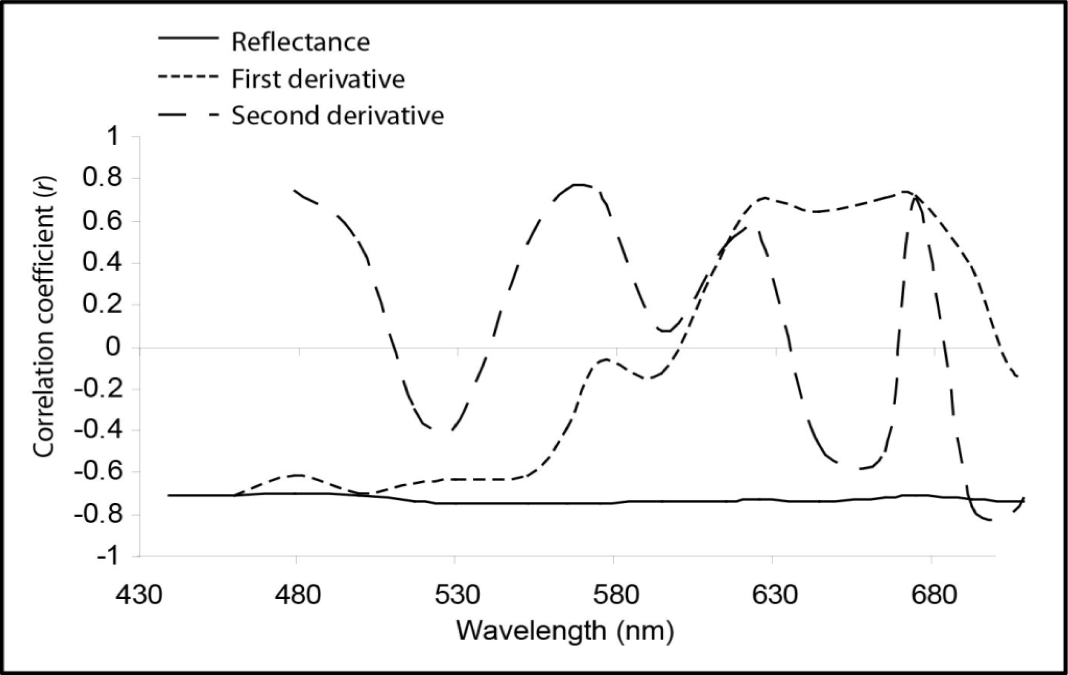
The linear correlation between average live coral and image-extracted reflectance (from the buffer region around each corresponding field transect or grid), first derivative and second derivative at all wavelengths (n = 18) is shown in Figure 6. In the reflectance domain, the correlation with coral cover remains relatively constant (r = −0.7) across the entire spectrum. This means that irrespective of the wavelength used, an increase in coral cover will always result in a decrease in reflected light. This suggests that corals absorb incoming light more strongly than their surrounding benthos. The same negative relationship was reported previously [33], though this relationship is stronger (higher r) with the image data rather than that presented with field spectrometer simulations.
Spectral reflectance curves of corals and other reef benthic features have been documented previously in numerous studies [18,20,22,30,4851]. These studies show that although some wavelengths absorb light more strongly than others, corals are generally “dark” targets. Corals do reflect considerably more light in the near infra-red wavelengths, however this will rarely be seen in image data where corals are submerged in water that strongly absorbs longer wavelengths. Darker targets could also represent increased algal coverage or even seagrass in some cases. As seagrass is not commonly found on Heron Reef, it was not considered in the modeling and index development, though testing in areas of extensive macroalgae and seagrass would be beneficial and provide a more complete analysis of the index.
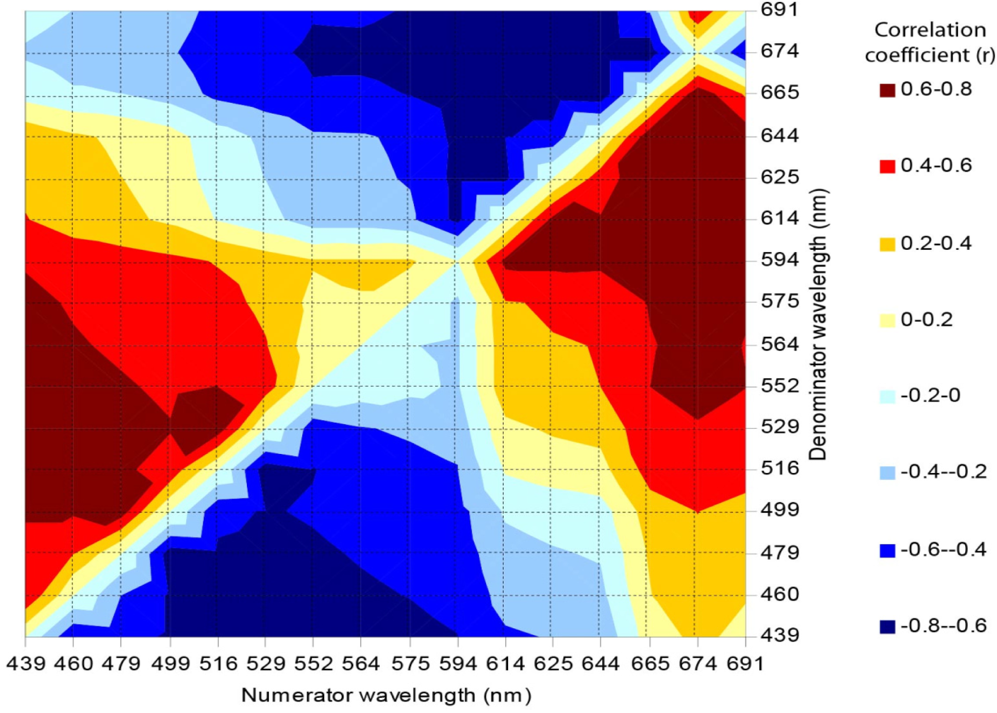
There were a number of wavelengths observable on the first and second derivative correlation curves that suggest sensitivity to variations in live coral cover (Figure 6). Reflectance along with first and second derivatives at 564 nm appear to be most sensitive to live coral cover variations (r = 0.79). The second derivative of this wavelength also demonstrated a strong correlation with variations in coral cover using field spectrometer data and simulated mixtures of benthic feature types [33]. A band ratio of 529:439 nm showed the greatest sensitivity to live coral cover variations (r = −0.76), though several other band combinations were also highly correlated (Figure 7).
There are similarities between the correlograms presented here and those based on simulated mixtures from field spectrometer data and shown previously (Figure 8). However, there are also several discrepancies that deserve recognition and further consideration. There are a number of reasons why the field spectrometer and image data would show different results. It is important to understand the cause of each difference to determine which method will be the most accurate. Differences that could be caused by the field spectrometer data include the assumption of linear mixing, inadequate characterization of representative “endmembers”, and the lack of consideration to water column effects. These have been addressed as recognized limitations to the simulation method.
The image-derived method is not free from error either. The inability to tie field survey (benthic features) information to corresponding individual pixels due mis-registration errors is the most likely cause for discrepancy when using the image correlations. This was addressed by aggregating survey data along selected transects that were considered to be the most homogeneous, but there will always be some variability. The second possible cause for discrepancy is the pre-processing operations that were applied. While every attempt was made to ensure spectral integrity of the data at each stage of the corrections, perfection is impossible. The result of small errors in both simulated and image methods are most likely the cause of the discrepancies seen in correlation values (Figure 8). The derivative correlogram form appears similar for both image and simulation methods, but with a slight offset in the longer wavelengths. This was presumably due to variable water depths in the image-based method.
After taking into account the correlation between live coral cover and spectral reflectance, first and second order derivatives, the second derivative around 564 nm was selected as the most effective index to apply to the CASI-2 image data (r2 = 0.63). Note that this corresponds directly to the testing done previously using solely field spectrometer data with various simulated mixes [33]. The linear correlation between coral cover and this transformation is shown in Figure 9. This regression equation was then applied to convert the relative coral cover image to absolute values (y = 0.9784x + 65.425). It should be noted here that while the second derivative around 564 nm may prove useful for mapping relative coral cover with imagery over other coral reefs, the absolute calibration equation should be recalculated for individual images using the appropriate field survey data.

3.3. Live Coral Cover Index Application and Validation

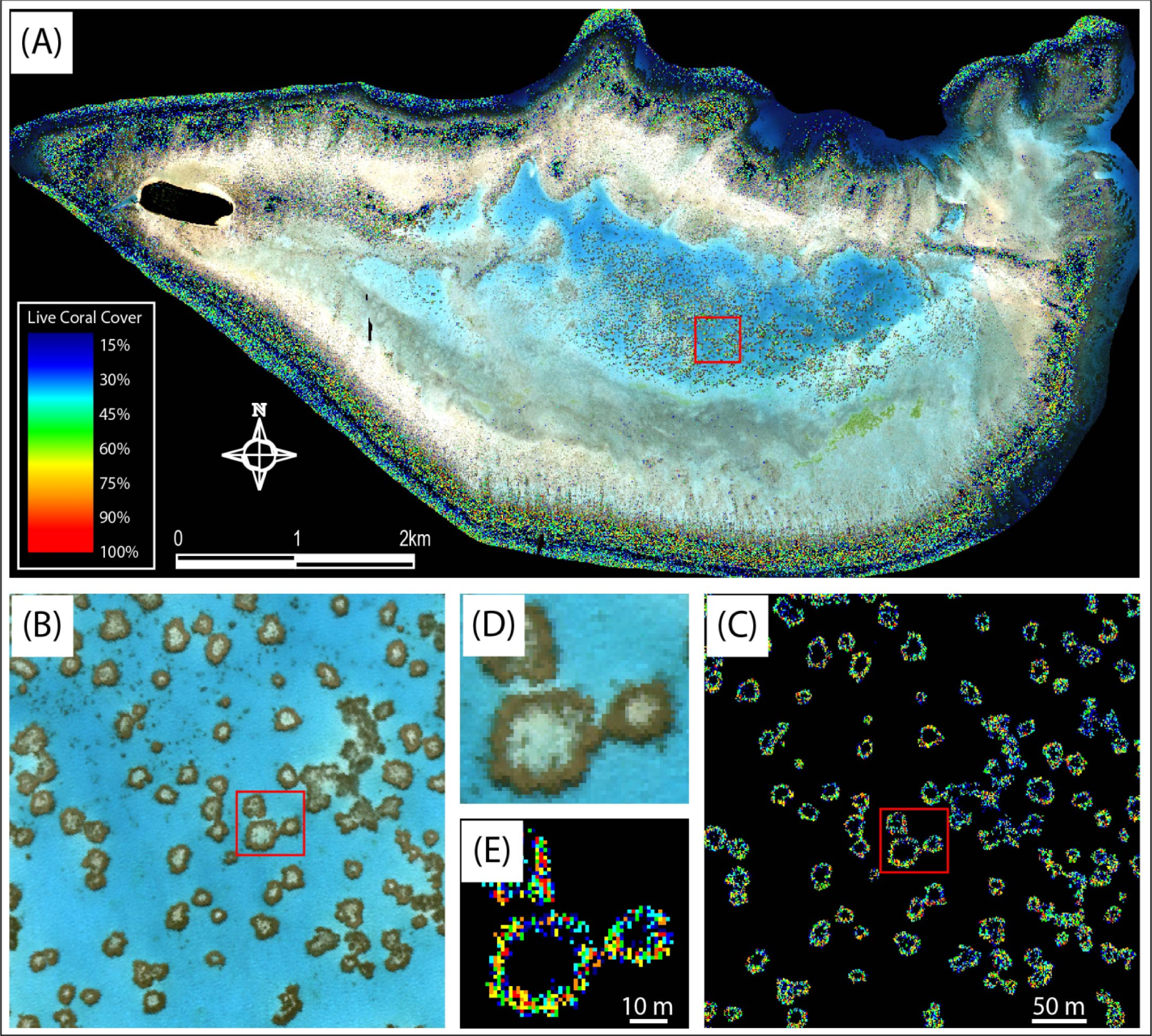
The patterns of coral cover on Heron Reef have been observed and well documented previously [37,39,40,5254]. Scopélitis, Andréfouët [34] have also studied how these patterns have changed over time in a small area of the reef. These studies provide a basis for comparison of both field and image analysis provided here. The most obvious pattern observed from the image data of Heron Reef after application of the index is the large areas of reef that fall outside the scale of the index, i.e., coral is not mapped in these areas. However, this is a valid result, as it has been noted previously that Heron, like the other Capricorn Bunker reefs, is characterized by a large sandy zone and lagoon with sand as the dominant substrate [37]. The deep lagoon consists of very fine sediments and patch reefs with coral and coralline algae [37]. Figure 10 shows the index values overlaid on the original CASI-2 image data with insets from both original and index images taken from patch reefs in the deep lagoon. Areas within and around the patch reefs seen as sandy substrate in the original image are clearly delineated as black using the index, despite the variation in depth (2 m–6 m) between the deep lagoon and surrounding areas.
When comparing the field data validation sites with image the data (Figure 11A), it is clear that the correlation between these variables is not as strong as that observed when using the calibration data (Figure 9). It is possible that this is for a number of reasons. Firstly, the calibration data selected were those sites considered to be most homogenous in terms of their live coral cover. This means that any spatial mis-registration between field and image data would be less pronounced. The validation data sites were therefore more variable. The location on the reef might also play a part. For example, the deep and shallow lagoons, as well as the rubble zones show similar levels of coral cover when using either the field survey, or image derived method (Figure 11B). Yet, the reef crest and slope demonstrate the greatest level of disagreement between field and image data.
Based on field and image data, the deep and shallow lagoons have considerably less live coral than the remainder of the reef (Figure 11). There is also less variability (lower standard deviation) in terms of coral cover in the lagoons. This is because the dominant feature here is the sandy substrate. Within the deep lagoon, shallow lagoon, and rubble zone, agreement between image derived and field data observed live coral cover is high. However the field survey does suggest higher levels of coral cover in the reef crest zone than is calculated using the index. This may indicate that the index is depth limited and will underestimate the coverage in deeper areas. Another point to note is that vertically based surveys are likely to underestimate coral cover in the steeper reef crest areas. Horizontally, these are narrow zones, but traditionally they also contain the highest level of coral cover and diversity.
It is possible that the results contained herein may be enhanced by conducting bathymetric correction prior to index application and this could be a path for further investigation. However, the intent of the study was to create a simple index for broad application. Our prequel study [33] actually demonstrates through extensive modeling that this same derivative finds the balance between being the most sensitive to variations in live coral cover, whilst being least sensitive to water column attenuation. In addition, a good bathymetric correction often requires prior knowledge, whereas this technique is attempting to provide a quick and simple mapping method.
The high spatial resolution data results in a somewhat salt and pepper effect upon application of the index. Without performing a smoothing operation, this makes broad scale generalizations about the variations in spatial distribution of coral cover difficult. However, to perform post processing smoothing will, by definition, remove the spatial detail in the image data, thus defeating the purpose of purchasing such high resolution image data.

3.4. Validity and Limitations to the Live Coral Cover Index

One of the most noticeable challenges with calibrating and validating image data is linking field, image and other spatial data sets with confidence. What is theoretically and statistically sound may not be logistically possible, particularly in marine environments [55]. Miss-registration between field and image data can cause calibration and validation statistics to be incorrect, especially at the local scale, where it is suggested that corals are not spatially correlated with their neighbors [52]. The effect of this is that a survey conducted in one location may yield a completely different coral cover calculation to that calculated a small distance away. This paper presents field survey data that were obtained from a boat, or by a diver or snorkeler close to the substrate. The method of locating survey sites was based on a tracking GPS that was attached to the diver or snorkeler. While every effort was taken to position the GPS receiver directly above the diver, currents and winds always cause drift. Transect and grid survey sites were selected to be as spatially homogenous as possible with respect to live coral cover to help reduce the problem of mis-registration. Even so, there was a great deal of variability observed within both field and image data at all sites. The calibration sites were then selected to be the most homogenous of all sites, and here it can be seen that the coral cover index was highly correlated with corresponding field survey (r2 = 0.63). When considering the validation survey sites, this relationship was not as strong.
As with any method of mapping submerged habitats with optical data, this method is limited to clear, shallow waters where the bottom reflectance in the selected wavelengths is greater than the reflectance of the water or its constituents in the same electromagnetic radiation regions. Here the limitations to ‘clear’ water cannot be defined, but previous work and model simulations suggests that this method is restricted to waters shallower than 10 m when the water column chlorophyll is less than 0.91 mg/m3 [33]. The spatial variation in water quality was not known at the time of image acquisition, so this suggestion cannot be verified. However, the wavelengths selected in this study fall within a region of the electromagnetic spectrum that is least affected by water column and atmospheric absorption and scattering, and should therefore prove robust under a variety of environmental conditions.
Several considerations were suggested by Joyce and Phinn [33] before the simulated data could be verified as an image-based index. These included both environmental (atmospheric effects, sea-state and sun glitter, air-sea interface, water column absorption and scattering, dissolved and suspended matter, depth, substrate topography and structure) and sensor specific effects (spatial, spectral and radiometric dimensions, viewing geometry). By extracting statistics from an image that was corrected for a number of these effects (atmospheric, sun glint, air-sea interface, viewing geometry), the best results possible were achieved with the models that were used. It should be noted here also that despite the number of challenges and level of sensor and environmental ‘noise, it has been shown that these factors are minor compared to the challenge presented by spectral mixing and heterogeneity at the pixel level [23]. Improvements may still be possible through further testing and validation at other reef locations and testing with the radiometric, spatial, and spectral characteristics of other sensors. However the aim was to calibrate and validate a simple method for mapping live coral cover that may be implemented with little to no ancillary data, and little user expertise. This index provides a means to map relative coral cover that may then be converted to an absolute estimate with the appropriate field survey data.
At the conception of the idea to create a spectral index for coral cover mapping, it was intended to select a band ratio that produced the most accurate results. However, through the extensive testing and validation shown here and previously through simulated data [33], results show that the derivative at a single wavelength (564 nm) consistently produced the most accurate result. This study does demonstrate that hyperspectral data is not required per se, however finding a multispectral sensor with the appropriately placed bands is a challenge. It may be possible to continue this testing using combination of the green and yellow bands on the Worldview-2 satellite or soon to be launched Worldview-3. If this was successful, it would certainly increase the utility of an index within this spectral region.

4. Conclusions and Future Work

While the initial input data set was hyperspectral, it has been shown with a second order derivative transformation around 564 nm, live coral cover can be mapped simply, effectively and relatively accurately on Heron Reef (24 km2). These findings support those of the prequel study using field spectrometry and modeling. Calibration data showed a high level of agreement between the field and image data, though the patterns in the validation sites were less clear. The latter could be attributed to a number of factors associated with the heterogeneity of the validation sites and positioning. The index was calibrated on the highest quality sites, while this could not be extended to all sites due to the inherent difficulties in sampling in this environment. Continued work on confidently determining field positioning with respect to image data in marine environments is encouraged.
The calibration of the index was based on CASI-2 image data that had been subjected to the highest level of pre-processing available to provide spectral data as free from contaminants as possible. However, such a high level of processing is time consuming and not always practical. In addition, with the suggestion of a simple mapping method, ideally the minimum pre-processing requirements need to be determined. Unfortunately such testing was outside the scope of this study, but is recommended as a worthy follow-up, possibly in combination with reviewing the potential of this method with contemporary sensors such as Worldview-2, although the input bands would need to be modified according to that sensor’s spectral properties.
Testing with the new generation of satellite sensors such as Worldview 2 will assess the index for broader spatial application, but may not address the true accuracy of the method. This is because there will always be uncertainty related to the spatial matching of field and image data at the spatial resolution of these sensors. To address this, we recommend a fine scale in-situ imaging survey. This could be conducted in a number of ways that truly leverage the recent advances in sensor and platform technology. It would be ideal to submerge a hyperspectral imaging device and obtain data whereby the pixel size was considerably smaller than the feature of interest. A range of resampling procedures could then be conducted to test the accuracy and limits of the live coral index at various spatial scales. Short of submerging the system, a low flying unmanned airborne vehicle could also obtain considerably higher spatial resolution than satellite or other manned platforms. This same technique could ultimately be used to scale up to hyperspectral spaceborne sensors with even courser resolution than the imagery used here.
There are currently several methods available for benthic feature type mapping in aquatic environments, and only one potential technique has been presented here. Its effectiveness has been proven in this context, while a follow up paper will compare and contrast its cost effectiveness and accuracy with other available methods for mapping coral reefs.
Spectral indices such as that presented here have been extremely useful for time series analysis for both terrestrial and oceanic environments. With high radiometric resolution sensors, small changes in the index values should be detectable, thus with further testing, this technique may become an objective and rapid method incorporated into multi-date analysis for monitoring health, decline and recovery of coral cover in reef ecosystems.

Acknowledgments

The study was funded by a University of Queensland Mid-Year Scholarship to K. Joyce; an Australian Research Council grant to S. Phinn, D. Neil and W.C. Dennison; The University of Queensland’s School of Geography, Planning and Architecture; Centre for Marine Studies; and Heron Island Research Station; CSIRO Land and Water; and the World Bank Global Environment Fund Coral Reefs project grant to Peter Mumby. Thank you to the reviewers who provided a significant amount of feedback on early drafts of this manuscript, and the thesis from which it originated. Thank you to CSIRO Land & Water (Arnold Dekker) for technical assistance with acquisition and processing of the CASI-2 data; Justin Marshall (UQ Vision Touch and Hearing Research Centre) and Tiit Kutser/CSIRO Earth Observations Centre and Environmental Remote Sensing Group for the use of their spectral libraries; and to Diana Kleine and Marine Botany, UQ for providing the graphics library that formed the basis of several figures presented in this manuscript.

Conflicts of Interest

The authors declare no conflict of interest.

References and Notes

  1. Hopley, D. Aerial Photography and Other Remote Sensing Techniques. In Coral Reefs: Research Methods; Stoddart, D.R., Johannes, R.E., Eds.; UNESCO: Paris, France, 1978; pp. 23–44. [Google Scholar]
  2. Jupp, D.L.B. The Application and Potential of Remote Sensing in the Great Barrier Reef Region; Great Barrier Reef Marine Park Authority: Townsville, QLD, Australia, 1986; p. 56. [Google Scholar]
  3. Jupp, D.L.B.; Heggen, S.J.; Mayo, K.K.; Kendal, S.W.; Bolton, J.R.; Harrison, B.A. The BRIAN Handbook: An Introduction to Landsat and the BRIAN (Barrier Reef Image Analysis) Systems for Users; Institute of Biological Resources, Commonwealth Scientific and Industrial Research Organization Australia: Melbourne, Australia, 1985. [Google Scholar]
  4. Kuchler, D.A. Remote sensing: What can it offer coral reef studies? Oceanus 1986, 29, 90–92. [Google Scholar]
  5. Kuchler, D.A.; Bina, R.T.; van R Classen, D. Remote sensing of coral reefs. Ascent 1988, 16, 28. [Google Scholar]
  6. Kuchler, D.A.; Jupp, D.L.B.; van R Claasen, D.B.; Bour, W. Coral reef remote sensing applications. Geocarto Int 1986, 4, 3–15. [Google Scholar]
  7. Andréfouët, S.; Kramer, P.; Torres-Pulliza, D.; Joyce, K.E.; Hochberg, E.J.; Garza-Perez, R.; Mumby, P.J.; Riegl, B.; Yamano, H.; White, W.H.; et al. Multi-sites evaluation of IKONOS data for classification of tropical coral reef environments. Remote Sens. Environ 2003, 88, 128–143. [Google Scholar]
  8. Mumby, P.J.; Clark, C.D.; Green, E.P.; Edwards, A.J. Benefits of water column correction and contextual editing for mapping coral reefs. Int. J. Remote Sens 1998, 19, 203–210. [Google Scholar]
  9. Mumby, P.J.; Green, E.P.; Clark, C.D.; Edwards, A.J. Digital analysis of multispectral airborne imagery of coral reefs. Coral Reefs 1998, 17, 59–69. [Google Scholar]
  10. Mumby, P.J.; Green, E.P.; Edwards, A.J.; Clark, C.D. Coral reef habitat-mapping: How much detail can remote sensing provide? Mar. Biol 1997, 130, 193–202. [Google Scholar]
  11. Mumby, P.J.; Edwards, A.J. Mapping marine environments with IKONOS imagery: Enhanced spatial resolution can deliver greater thematic accuracy. Remote Sens. Environ 2002, 82, 248–257. [Google Scholar]
  12. Kobryn, H.T.; Wouters, K.; Beckley, L.E.; Heege, T. Ningaloo reef: Shallow marine habitats mapped using a hyperspectral sensor. PLoS One 2013, 8, e70105. [Google Scholar]
  13. Roelfsema, C.; Phinn, S. Validation. In Coral Reef Remote Sensing: A Guide for Multi-Level Sensing Mapping and Assessment; Goodman, J.A., Purkis, S., Phinn, S., Eds.; Springer: New York, NY, USA, 2013. [Google Scholar]
  14. Phinn, S.R.; Roelfsema, C.M.; Mumby, P.J. Multi-scale, object-based image analysis for mapping geomorphic and ecological zones on coral reefs. Int. J. Remote Sens 2012, 33, 3768–3797. [Google Scholar]
  15. Leon, J.; Woodroffe, C.D. Improving the synoptic mapping of coral reef geomorphology using object-based image analysis. Int. J. Geogr. Inf. Sci 2011, 25, 949–969. [Google Scholar]
  16. Roelfsema, C.; Phinn, S.; Jupiter, S.; Comley, J.; Albert, S. Mapping coral reefs at reef to reef-system scales, 10 s–1000 s km2, using object-based image analysis. Int. J. Remote Sens 2013, 34, 6367–6388. [Google Scholar]
  17. Hochberg, E.J.; Atkinson, M.J. Capabilities of remote sensors to classify coral, algae, and sand as pure and mixed spectra. Remote Sens. Environ 2003, 85, 174–189. [Google Scholar]
  18. Holden, H.; LeDrew, E. Hyperspectral identification of coral reef features. Int. J. Remote Sens 1999, 20, 2545–2563. [Google Scholar]
  19. Hedley, J.D.; Mumby, P.J. A remote sensing method for resolving depth and subpixel composition of aquatic benthos. Limnol. Oceanogr 2003, 48, 480–488. [Google Scholar] [Green Version]
  20. Hedley, J.D.; Mumby, P.J.; Joyce, K.E.; Phinn, S.R. Spectral unmixing of coral reef benthos under ideal conditions. Coral Reefs 2004, 23, 60–73. [Google Scholar]
  21. Goodman, J.A.; Ustin, S.L. Airborne Hyperspectral Analysis of Coral Ecosystems in the Hawaiian Islands. Proceedings of 30th International Symposium for Remote Sensing of the Environment, Honolulu, HI, USA, 10–14 November 2003.
  22. Hamylton, S. Estimating the coverage of coral reef benthic communities from airborne hyperspectral remote sensing data: Multiple discriminant function analysis and linear spectral unmixing. Int. J. Remote Sens 2011, 32, 9673–9690. [Google Scholar]
  23. Hedley, J.D.; Roelfsema, C.M.; Phinn, S.R.; Mumby, P.J. Environmental and sensor limitations in optical remote sensing of coral reefs: Implications for monitoring and sensor design. Remote Sens 2012, 4, 271–302. [Google Scholar]
  24. Lee, Z.P.; Carder, K.L.; Mobley, C.D.; Steward, R.G.; Patch, J.S. Hyperspectral remote sensing for shallow waters. A semianalytical model. Appl. Opt 1998, 37, 6329–6338. [Google Scholar]
  25. Chen, Y.; Gillieson, D. Evaluation of Landsat TM vegetation indices for estimating vegetation cover on semi-arid rangelands: A case study from Australia. Can. J. Remote Sens 2009, 35, 435–446. [Google Scholar]
  26. Xavier, A.C.; Vettorazzi, C.A. Mapping leaf area index through spectral vegetation indices in a subtropical watershed. Int. J. Remote Sens 2004, 25, 1661–1672. [Google Scholar]
  27. O’Reilly, J.E.; Maritorena, S.; Mitchell, B.G.; Siegel, D.A.; Carder, K.L.; Garver, S.A.; Kahru, M.; McClain, C. Ocean color chlorophyll algorithms for SeaWiFS. J. Geophys. Res 1998, 103, 24937–24953. [Google Scholar]
  28. Franklin, S.E. Remote Sensing for Sustainable Forest Management; CRC Press: Boca Raton, FL, USA, 2001; p. 407. [Google Scholar]
  29. Mumby, P.J. Assessing Seagrass Standing Crop. In Remote Sensing Handbook for Tropical Coastal Management; Edwards, A.J., Ed.; UNESCO: Paris, France, 2000; pp. 237–244. [Google Scholar]
  30. Minghelli-Roman, A.; Chisholm, J.R.M.; Marchioretti, M.; Jaubert, J. Discrimination of coral reflectance spectra in the Red Sea. Coral Reefs 2002, 21, 307–314. [Google Scholar]
  31. Bour, W.S.; Dupont, S.; Joannot, P. Establishing a “SPOT” thematic neo-channel for the study of hard-of-access lagoon environments: Example of application on the growth area of the New Caledonian Reefs. Geocarto Int 1996, 11, 29–39. [Google Scholar]
  32. Collin, A.; Hench, J.L.; Planes, S. A Novel Spaceborne Proxy for Mapping Coral Cover. Proceedings of the 12th International Coral Reef Symposium, Cairns, QLD, Australia, 9–13 July 2012.
  33. Joyce, K.E.; Phinn, S.R. Spectral index development for mapping live coral cover. J. Appl. Remote Sens 2013. [Google Scholar] [CrossRef]
  34. Scopélitis, J.; Andréfouët, S.; Phinn, S.; Done, T.; Chabanet, P. Coral colonisation of a shallow reef flat in response to rising sea level: Quantification from 35 years of remote sensing data at Heron Island, Australia. Coral Reefs 2011, 30, 951–965. [Google Scholar]
  35. Mumby, P.J.; Hedley, J.D.; Chisholm, J.R.M.; Clark, C.D.; Ripley, H.T.; Jaubert, J. The cover of living and dead corals from airborne remote sensing. Coral Reefs 2004, 23, 171–183. [Google Scholar]
  36. Phinn, S.R.; Joyce, K.E.; Roelfsema, C.M. Airborne Hyperspectral Image Data of Heron Reef, Australia; University of Queensland: Brisbane, QLD, Australia, 2012. [Google Scholar]
  37. Flood, P. The Geomorphology of A Coral Reef. In A Coral Reef Handbook; Mather, P., Bennett, I., Eds.; Surrey Beatty & Sons: Baulkham Hills, NSW, Australia, 1993; pp. 7–15. [Google Scholar]
  38. Roelfsema, C.M.; Joyce, K.E.; Phinn, S.R. Evaluation of Benthic Survey Techniques for Validating Remotely Sensed Images of Coral Reefs. Proceeings of the International Coral Reef Symposium, Okinawa, Japan, 28 June–2 July 2004.
  39. Joyce, K.E.; Phinn, S.R.; Roelfsema, C.; Neil, D.T.; Dennison, W.C. Combining landsat ETM+ and reef check classifications for mapping coral reefs: A critical assessment from the southern great barrier reef, Australia. Coral Reefs 2004, 23, 21–25. [Google Scholar]
  40. Ahmad, W.; Neil, D.T. An evaluation of Landsat Thematic Mapper (TM) digital data for discriminating coral reef zonation: Heron Reef (GBR). Int. J. Remote Sens 1994, 15, 2583–2597. [Google Scholar]
  41. Joyce, K.E.; Phinn, S.R.; Roelfsema, C.; Neil, D.T.; Dennison, W.C. Mapping the Southern Great Barrier Reef using Landsat ETM and the Reef Check Classification Scheme. Proceedings of the 11th Australasian Remote Sensing and Photogrammetry Conference, Brisbane, QLD, Australia, 2–6 September 2002.
  42. Hodgson, G. A global assessment of human effects on coral reefs. Mar. Pollut. Bull 1999, 38, 345–355. [Google Scholar]
  43. Joyce, K.E.; Phinn, S.R.; Roelfsema, C.M. Weighing the costs and benefits of image acquisition and pre-processing for coral reef remote sensing. Position Mag 2003, 8, 76–78. [Google Scholar]
  44. Joyce, K.E. A. Method for Mapping Live Coral Cover Using Remote Sensing. In School of Geography, Planning and Architecture; University of Queensland: Brisbane, Australia, 2005; p. 132. [Google Scholar]
  45. Joyce, K.E.; Phinn, S.R. Hyperspectral analysis of chlorophyll content and photosynthetic capacity of coral reef substrates. Limnol. Oceanogr 2003, 48, 489–496. [Google Scholar]
  46. Hopley, D. The Geomorphology of the Great Barrier Reef: Quaternary Development of Coral Reefs; John Wiley & Sons: Brisbane, QLD, Australia, 1982. [Google Scholar]
  47. Hatcher, B.G. Coral reef ecosystems: How much greater is the whole than the sum of the parts? Coral Reefs 1997, 16, S77–S91. [Google Scholar]
  48. Hochberg, E.J.; Atkinson, M.J. Spectral discrimination of coral reef benthic communities. Coral Reefs 2000, 19, 164–171. [Google Scholar]
  49. Hochberg, E.J.; Atkinson, M.J.; Andréfouët, S. Spectral reflectance of coral reef bottom-types worldwide and implications for coral reef remote sensing. Remote Sens. Environ 2003, 85, 159–173. [Google Scholar]
  50. Holden, H.; LeDrew, E. Spectral discrimination of healthy and non-healthy corals based on cluster analysis, principal components analysis, and derivative spectroscopy. Remote Sens. Environ 1998, 65, 217–225. [Google Scholar]
  51. Wettle, M.; Ferrier, G.; Lawrence, A.J.; Anderson, K. Fourth derivative analysis of Red Sea coral reflectance spectra. Int. J. Remote Sens 2003. [Google Scholar] [CrossRef]
  52. Reichelt, R.E.; Bradbury, R.H. Spatial patterns in coral reef benthos: Multiscale analysis of sites from three oceans. Mar. Ecol. Prog. Ser 1984, 17, 251–257. [Google Scholar]
  53. Mayo, K.K.; Jupp, D.L.B.; Heggan, S.J.; Kendall, S.W. Heron Island: Field Notes and Data Sheets; CSIRO Div. Water & Land Res. Tech. Mem.: Canberra, ACT, Australia, 1985; p. 14. [Google Scholar]
  54. Bennett, I. Reef Zonation. In A Coral Reef Handbook; Mather, P., Bennett, I., Eds.; Surrey Beatty & Sons: Baulkham Hills, QLD, Australia, 1993; pp. 179–184. [Google Scholar]
  55. Roelfsema, C.; Phinn, S. Integrating field data with high spatial resolution multispectral satellite imagery for calibration and validation of coral reef benthic community maps. J. Appl. Remote Sens 2010. [Google Scholar] [CrossRef] [Green Version]
Figure 1. Heron Reef study site, southern Great Barrier Reef. All field data calibration (n = 22) and validation (n = 273) sites are shown. The geomorphic categories based on [37] are also outlined. “Waypoints” correspond to April 2001 field survey; “Transects” correspond to November 2002 field survey; and “Grids” correspond to May/June 2003 field survey.
Remotesensing 05 06116f1
Figure 2. Field survey methods (A) 50 m point sampling taking two photos from a submerged camera at the side of the boat (as in April 2001); (B) 50 m transect with digital photos taken at 2 m intervals (as in November 2002); and (C) 5 × 5 m grid with digital photos taken every 1 m grid cell (as in May/June 2003).
Remotesensing 05 06116f2
Figure 3. Buffer creation around (A) discrete sampling points; (B) transect surveys; and (C) grid surveys.
Remotesensing 05 06116f3
Figure 4. Field determined coral cover overlaid on CASI-2 image data. Each survey point has been categorized into one of the five live coral cover categories based on live coral estimation from digital photos. Note that the size of each survey point has been enlarged for visibility purposes.
Remotesensing 05 06116f4
Figure 5. Average coral cover based on field survey of the sites used for index calibration. Bars indicate standard deviation. Site name prefixed by GR denotes a grid calibration site; SN denotes a snorkel calibration site; and DV denotes a dive transect calibration site. See Figure 1 for location of grid, snorkel and dive transect calibration sites.
Remotesensing 05 06116f5
Figure 6. Correlogram of linear correlation coefficients between live coral cover and spectral reflectance, first derivative and second derivative.
Remotesensing 05 06116f6
Figure 7. Correlation coefficients between simple band ratios and coral cover.
Remotesensing 05 06116f7
Figure 8. Comparison of field spectrometer simulations with applied CASI-2 image data-linear correlations for relationship between live coral and (A) reflectance; (B) first derivative; and (C) second derivative.
Remotesensing 05 06116f8
Figure 9. Linear correlation equation determination between live coral cover and 2nd derivative around 564 nm.
Remotesensing 05 06116f9
Figure 10. (A) Overlay of live coral cover index applied to CASI-2 image of Heron Reef; (B) CASI-2 subset from deep lagoon; (C) live coral cover index application from deep lagoon; (D) CASI-2 subset from patch reef in lagoon; and (E) live coral cover index application from patch reef in lagoon. NB: The same live coral cover scale shown in (A) is used in (C) and (E).
Remotesensing 05 06116f10
Figure 11. (A) Comparison of field survey data with image derived live coral cover estimate for all validation sites; and (B) Comparison of mean percentage live coral cover calculated from field and image data per geomorphic zone. Bars indicate standard deviation.
Remotesensing 05 06116f11