Article

An Object Model for Integrating Diverse Remote Sensing Satellite Sensors: A Case Study of Union Operation

1
Faculty of Information Engineering, China University of Geosciences (Wuhan), Wuhan 430074, China
2
State Key Laboratory for Information Engineering in Surveying, Mapping and Remote Sensing, Wuhan University, Wuhan 430079, China
*
Authors to whom correspondence should be addressed.
Remote Sens. 2014, 6(1), 677-699; https://doi.org/10.3390/rs6010677
Submission received: 12 October 2013 / Revised: 1 December 2013 / Accepted: 31 December 2013 / Published: 7 January 2014

Abstract

:
In the Earth Observation sensor web environment, the rapid, accurate, and unified discovery of diverse remote sensing satellite sensors, and their association to yield an integrated solution for a comprehensive response to specific emergency tasks pose considerable challenges. In this study, we propose a remote sensing satellite sensor object model, based on the object-oriented paradigm and the Open Geospatial Consortium Sensor Model Language. The proposed model comprises a set of sensor resource objects. Each object consists of identification, state of resource attribute, and resource method. We implement the proposed attribute state description by applying it to different remote sensors. A real application, involving the observation of floods at the Yangtze River in China, is undertaken. Results indicate that the sensor inquirer can accurately discover qualified satellite sensors in an accurate and unified manner. By implementing the proposed union operation among the retrieved sensors, the inquirer can further determine how the selected sensors can collaboratively complete a specific observation requirement. Therefore, the proposed model provides a reliable foundation for sharing and integrating multiple remote sensing satellite sensors and their observations.

Graphical Abstract

1. Introduction

According to the US National Aeronautics and Space Administration (NASA), approximately 3,000 satellites, equipped with various heterogeneous sensors, are operating in Earth’s orbit [36]. With the increasing complexity of Earth Observation (EO) missions, a single sensor cannot effectively conform to these observation requirements, thereby necessitating the collaboration of a number of other sensors to yield a meaningful output [1]. The challenge of advanced EO systems is not to launch as many satellite sensors as possible, but the rational and comprehensive use of available sensors to provide efficient application support to certain complex observation tasks. Considering the heterogeneity of remote sensing satellite sensors, obtaining an integrated solution for accomplishing specific emergency tasks is difficult by the rapid, accurate, and uniform discovery of satisfactory sensors that can be reliably associated. The integration of remote sensing satellite sensors [2], which can be defined as the unified sharing of observation information provided by satellite sensors, and the synergistic use of multiple sensors for assistance in task accomplishments, is necessary [3].
With regard to sensor network environments, considerable attention has been paid in managing heterogeneous sensors [46]. However, these achievements primarily emphasize the bottom-level access, control, and planning of distributed and standalone sensors rather than the integration of mutually isolated sensors via the World Wide Web. Several studies [7,8] have encompassed different aspects of data integration from remote sensing satellite sensors; however, the integration of remote sensors has not been investigated. The Sensor Web Enablement (SWE) initiative developed by the Open Geospatial Consortium (OGC) defines a standard framework that aims to enable the interoperable use of sensor resources [9]. Di [10] demonstrates that all distributed or traditional standalone EO sensors will be converted to web-accessible sensors by complying with SWE interfaces and information standards. Blaschke et al. [11] conclude that the adoption of OGC sensor web technology can holistically integrate urban sensors. Sensor Model Language (SensorML) [12] is an SWE information standard that provides a flexible and general framework for describing sensor information. Sensor information [13] is the representation of an actual sensor and describes the physical characteristics of a sensor, the limitations posed by the environment on a sensor, and the performance of a sensor. The study [37] introduces a framework for web-based sensor discovery, wherein SensorML is adopted as the model for describing sensor information. SensorML-based information description frameworks have been used in various applications [3], such as the EU directive INSPIRE ( http://www.ec-gis.org/inspire/), EU-funded projects SANY ( http://sany-ip.eu) and OSIRIS ( http://www.osiris-fp6.eu), South Africa AFIS project [38], and US OOSTethys community project ( http://www.oostethys.org). Foerster et al. [14] state that integrating the sensor information into sensor web environments assists in accessing deployed sensors. Di [15] explains that the “availability of metadata for the Sensor Web can be very useful in discovery of the right sensor at right time and location with the right quality, and to achieve sensor interoperation.” However, current SensorML-based sensor information description frameworks do not consider unified metadata elements; therefore, such frameworks cannot completely satisfy the requirement for sharing and interoperating sensors and their observations [16,35]. Simply defining the sensor information description framework is insufficient in facilitating the unified discovery and integration of multiple sensors [17]. Our recent study [16] preliminarily analyzes the metadata requirements for sharing atmospheric satellite sensors and their observations and defines an eight-tuple metadata composition. However, the classification of satellite sensors is not considered.
Process and object-oriented programming techniques are two distinct programming paradigms for establishing a computer-readable model of the real world. These two programming paradigms have been studied extensively with regard to software architecture and computer programming [18,19]. Process-oriented programming emphasizes function-centric applications, whereas object-oriented programming focuses on object-centric modeling [20]. In sensor system modeling, available sensor description standards [29], such as IEEE 1451, ECHONET, Device Description Language (DDL), and Device Kit, tend to be applied in function-centric scenarios. IEEE 1451 is mainly used to define communication and network interfaces. ECHONET acts as an adapter for the networking and configuration of home devices. DDL follows a cross-layer design and focuses only on device interfacing. Device Kit provides a common interface for application codes to promote interaction with RFID readers and other device sensors and actuators. The above-mentioned standards provide certain functional representations for sensor systems; however, the reusability of these standards is poor as such standards are intended for function-specific applications. Compared with the process-oriented approach, the object-oriented approach chiefly relies on its closeness to the natural view of the real world. Object-oriented analysis uses properties and methods that are present in an object as the basic unit of the object-oriented model. In addition to saving the local state of information, the object-oriented approach can also perform operations on different objects. The properties and methods or the operations of an object are defined by a class [21]. The essential characteristics of the object-oriented approach include information hiding, encapsulation, and inheritance. By increasing the level of abstraction from the function level to the object level, the object-oriented model focuses on the real-world aspects and linkages of a system, thereby, providing a mapping relationship from real-world objects to model objects [22]. The object-oriented approach views the real world as a system with mutually cooperating objects. Bordogna et al. [23] state that the object-oriented paradigm for modeling applications has emerged in several fields such as computer-aided design, water catchment management, and geographic information systems. It is noteworthy that the object-oriented approach has also been applied to sensor systems, limited to sensor data integration [1], sensor process descriptions [12], sensor failure modes [25], sensor geolocation [26], and home-appliance-specific sensor networking [24,27]. However, studies implementing the object-oriented approaches in sensor modeling that are capable of integrating multiple remote sensors cannot be found in literature.
Satellite sensors differ in several aspects, such as sensor observation principle, intended application, and sensor information representation. The current problems involved in satellite sensors are as follows [9,28]: (1) the resources of a remote sensing satellite sensor are abundant but few resources are available or can be appropriately planned for a specific task; and (2) the effective integration of these diverse satellite sensors for collaborated observation is absent. In the current study, we propose an object model for the integration of diverse remote sensing satellite sensors, based on the object-oriented paradigm and the SWE standard information description framework. This paper begins with the Unified Modeling Language class diagram to show the object-oriented aspect of the proposed object model. Next, we analyze the meta-attribute description of different satellite sensors. Thereafter, the operations of sensor resource objects have been illustrated. Then, we illustrate the union operation, including its definition and algorithm design. Finally, the different information instances of resource attribute states are demonstrated. The union operation among satellite sensor resource objects is implemented. The proposed model has the following contributions: (1) performs as a standard descriptor for the logical unification of isolated satellite sensors, thus, enabling sensor discovery; and (2) acts as an indicator that assists the decision maker to formulate a sensor collaboration solution for a specific observation task.

2. Object Model of Remote Sensing Satellite Sensors

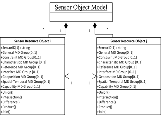
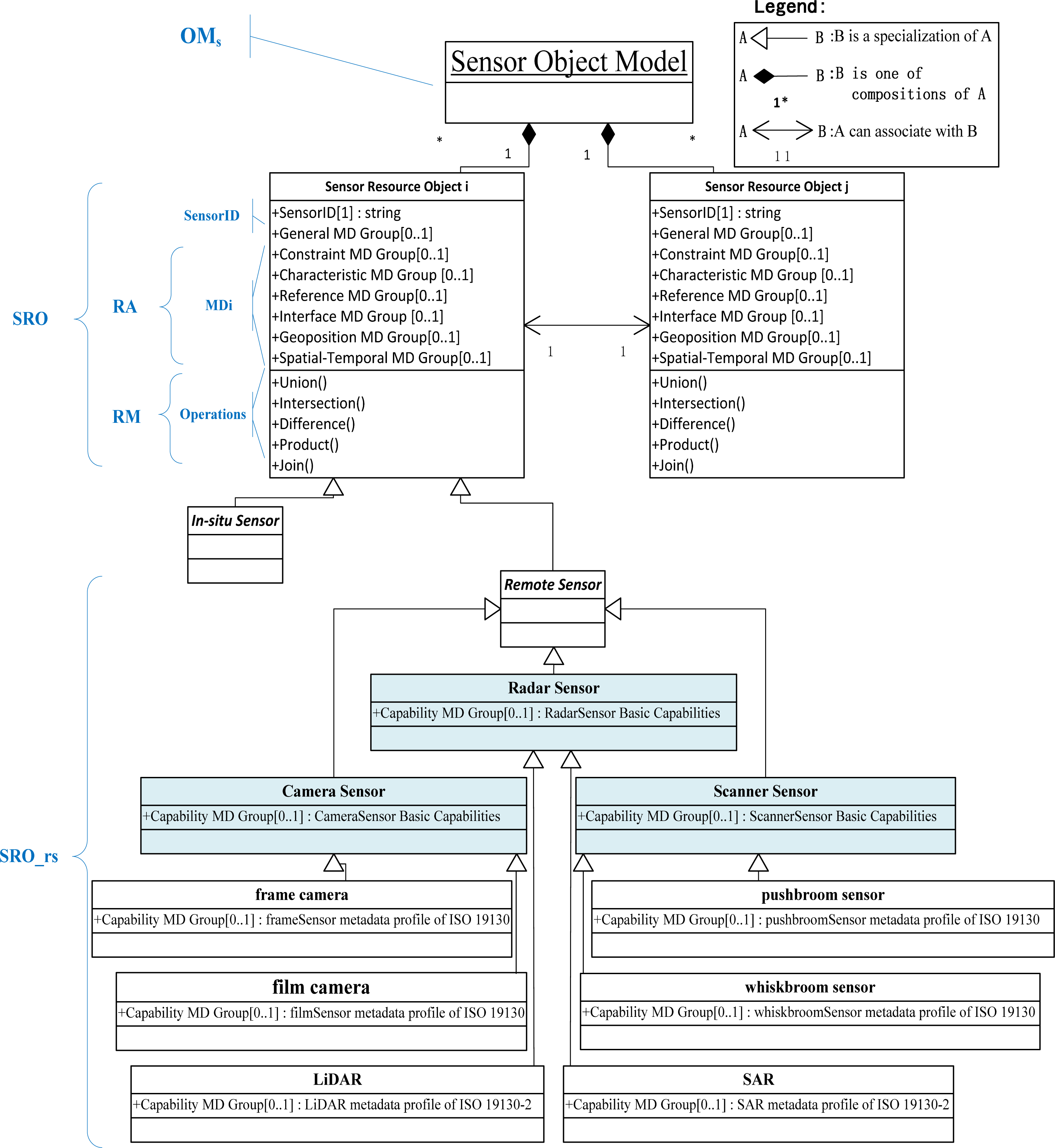
2.1. Conceptual Level of the Proposed Object Model

In this study, the proposed model considers each remote sensing satellite sensor as an independent object acting as a source that can collaborate with other sensor resource objects.
Figure 1 illustrates the conceptual level of the model by the basic notions of the object-oriented approach [31], which includes associations, compositions, and specializations. The sensor Object Models (OMs) is a set of Sensor Resource Objects (SRO). We can express OMs by using the following mathematical expression:
OM s = { SRO 1 , SRO 2 , , SRO n }
Each SRO represents a specialized sensor type. On the basis of the sensor characteristics [12], a sensor system can either perform the measurement in situ or remotely. We define In situ Sensor and Remote Sensor as two subclasses of the SRO class to ensure the comprehensiveness and versatility of the model (Figure 1). Our study mainly focuses on the Remote Sensor subclass. According to the classification of sources that enable the remote sensing of images in ISO 19130 [26] and 19130-2 standards [32], a Remote Sensor type can be specialized into the following classes: frame camera, film camera, pushbroom sensor, whiskbroom sensor, Synthetic Aperture Radar (SAR), and Light Detection and Ranging (LiDAR). These remote sensors can be further classified into three categories, namely, camera sensor, scanner sensor, and radar sensor.
Each concrete SRO instance encapsulates three basic elements: Sensor Identification (SensorID), Resource Attribute (RA), and Resource Method (RM), which can be expressed as that in Equation (2):
SRO = { SensorID , RA , RM }
where SensorID denotes the unique identification of the SRO, RA is a set of attribute state descriptions of the SRO, and RM is a set of methods of the SRO, wherein, the object relation operations are encapsulated.
Each concrete SRO instance has a unique RA. By using the SensorML framework as the reference [28], the RA equation can be expressed as follows:
RA i = { MD i } ( i = 1 , 2 , n )
where MDi is the metadata set of the concrete SRO. To assist integrators and analysts in obtaining a better understanding of the EO sensor system [13], our previous study [16] preliminarily analyzes the metadata requirements for sharing atmospheric satellite sensors and their observations, and MDi is defined as an eight-tuple composition:
MD i = { MD i G , MD i C , MD i CT , MD i CP , MD i R , MD i ST , MD i GP , MD i I } ( i = 1 , 2 , n )
where MD i G is the general metadata group, MD i C is the constraint metadata group, MD i CT is the characteristic metadata group, MD i CP is the capability metadata group, MD i R is the reference metadata group, MD i ST is the spatial-temporal metadata group, MD i GP is the geoposition metadata group, and MD i I is the interface metadata group. Each metadata group belongs to the enumerated type, and the detailed elements are described in Section 2.2.
The associated operations refer to relations between two or more external Sensor Resource Objects (SROs), including union, intersection, difference, product, and join. The metadata elements of the RA act as independent variables in these operations.
By referring to the above illustration, the remote sensing satellite sensor Object Model (OMrs) can be defined as a set of remote sensing SROs (SROs_rs). The SRO_rs can be expressed as follows:
SRO _ rs = { SensorID , RA _ rs , RM _ rs }
The remote sensor Resource Attribute (RA_rs) and remote sensor Resource Method (RM_rs) are described in detail in Sections 2.2 and 2.3, respectively.

2.2. Remote Sensor Resource Attribute of SRO_rs

In this section, we determine the elements of the RA_rs of SRO_rs. We adopt SensorML as the carrier to describe the attribute information of SRO_rs. SensorML provides only the description framework rather than the explicit and unified metadata elements for sharing and interoperating sensors. On the basis of SensorML, we [16] further analyze and define the metadata elements of atmospheric satellite sensors, where MD i G includes attributes such as keyword, sensor type, sensor name, sensor_associated_platform, platform type, platformID, and platform name. MD i C includes the sensor observation validity time and sharing levels of sensor and responsible centers. MD i CT includes mobility, measures, height, mass, power, and dimension. MD i R includes the URLs of the sensor’s online resources. MD i I mainly includes the web service interface used to access the sensors and related observations. MD i ST and MD i GP mainly contain the parameters used to determine the satellites’ dynamic trajectory. MD i CP considers the coarse-grained aspects of spatial, temporal, and spectral resolutions. All these elements have been reused from existing geospatial and sensor-related metadata standards [15,30] or have been newly extended to enable the sharing and interoperation of satellite sensors. However, we have not distinguished the fine-grained observation capabilities of each type of remote sensing satellite sensor.
The above analysis show that the description of the RA_rs of SRO_rs complies with the description of MDi (Section 2.1), and the fine-grained attribute elements of the seven metadata groups, namely, MD i G, MD i C, MD i CT, MD i R, MD i I, MD i ST, and MD i GP, can be completely obtained from the above (Table 1). However, MD i CP needs to be thoroughly refined depending on the specified type of remote sensor. Each type of remote sensor has its basic observation capabilities: band name, band_associated_application, spectral range, ground resolution, and so on. With regard to the remote imagery sensors, the geographic location of the dynamic sensor observations is a fundamental processing step before the acquired data become useful. Therefore, on the basis of the elements used to determine the satellites’ dynamic trajectory in MD i ST and MD i GP, the attributes used for geolocation, such as field of view (FOV), swath width, and side swing angle, are important capability indices in MD i CP. The ISO 19130 series describes a physical sensor model that enables users to determine the geographical location of dynamic sensor observations, that is, the attributes for geolocation can be extracted from the “SD_Geolocation Information” in the ISO 19130 series [26,32]. For example, the MD i CP of the whiskbroom sensor includes row spacing, focal length, and FOV, which can be obtained from the whiskbroom sensor metadata profile of the ISO 19130 standard [39]. On the contrary, the SAR contains a unique collection: polarization mode and operating frequency, which is referenced from the SAR metadata profile of the ISO 19130-2 standard [40]. Table 2 shows the details of MD i CP for a specific type of remote sensor.

2.3. Remote Sensor Resource Operations

The different SRO_rs instances can exhibit homogeneity and heterogeneity. Table 3 lists the logical structure of the proposed SRO_rs.
Table 4 shows two types of classifications of EO sensors: traditional and OGC SensorML-recognized classifications. Different sensor objects may have different meta-attributes, whereas all types of SRO_rs instances maintain five associated operations. Therefore, the logical structure of SRO_rs (Table 3) varies depending on the differing collections of MDi.
As mentioned above, this study reveals that satellite sensors that have the same meta-attribute node collections {A_1, A_2, …, A_n} satisfy the following mathematical proposition: {“Is_Same_PlatformHeightType” = Yes ∧ “Is_Same_Mobility” = Yes ∧ “Is_Same_Measures” = Yes}; such satellite sensors are considered homogenous. Otherwise, sensors that do not have the same meta-attribute nodes are classified as heterogeneous.
We assume that the proposed OMrs contains two SRO_rs instances: SRO1_rs and SRO2_rs. SRO′_rs represents the new virtual sensor object [33,34] obtained after performing certain types of relation algebraic operations, such as union, intersection, difference, product, and join. Similar to the metadata attribute set illustrated in the preceding section, homogeneous sensors are described to have the same meta-attribute collections {A_1, A_2, …, A_n}, and the number of meta-attribute columns is n. However, the description of heterogeneous sensor RAs differs in terms of the elements or columns of the meta-attributes. Tang et al. [29] state that union, intersection, and difference operations can only be undertaken within the homogeneous sets of two object spaces, i.e., these operations can only be applied in homogeneous SRO_rs instances. By contrast, the product and join operations can be performed between heterogeneous SRO_rs instances with differing meta-attribute columns.
For homogeneous SRO_rs instances, the included operations can be expressed as follows:
  • SRO'_rs = SRO1_rs ∪ SRO2_rs ≡ {t | t ∈ SRO1_rs ∨ t ∈ SRO2_rs}, where t is the meta-attribute variable of SRO′_rs. This operation is the union between two SRO_rs instances. SRO′_rs is the new SRO_rs that contains the comprehensive sensor observing capacity of SRO1_rs and SRO2_rs.
  • SRO'_rs = SRO1_rs ∩ SRO2_rs ≡ {t | t ∈ SRO1_rs ∧ t ∈ SRO2_rs}, where t is the meta-attribute variable of SRO'_rs. This operation is the intersection between the two SRO_rs instances. SRO'_rs is the current new SRO_rs having commonality between SRO1_rs and SRO2_rs.
  • SRO'_rs = SRO1_rs − SRO2_rs ≡ {t | t ∈ SRO1_rs ∧ t ∉ SRO2_rs}, where t is the meta-attribute variable of SRO'_rs. This operation is the difference between the two SRO_rs instances. SRO'_rs is the current new SRO_rs having sensor observation system meta-attributes that are present in SRO1_rs but not in SRO2_rs.
For heterogeneous SRO_rs instances, the included operations are as follows:
  • SRO'_rs = SRO1_rs × SRO2_rs ≡ {t | t = <t1, t2> ∧ t1 ∈ SRO1_rs ∧ t2 ∈ SRO2_rs}, where t1 and t2 are the meta-attribute variables of SRO'_rs. We assume that SRO1_rs has n-ary meta-attribute columns, and SRO2_rs has m-ary meta-attribute columns. This operation is the product of the two SRO_rs instances. SRO'_rs is the new SRO_rs wherein the first n-ary meta-attribute columns are the meta-attributes of SRO1_rs, and the succeeding m-ary meta-attribute columns are the meta-attributes of SRO2_rs.
  • SRO'_rs = SRO1_rs ⋈ SRO2_rs ≡ {t | t = <t1, t2> ∧ t1 ∈ SRO1_rs ∧ t2 ∈ SRO2_rs ∧ t1 [B] = t2[B]}, where t1 and t2 are the meta-attribute variables of SRO'_rs. SRO1_rs and SRO2_rs have the same meta-attribute column B = M D 1 A i = M D 2 A k, i.e., B is the common meta-attribute of these two SRO_rs instances and denotes the natural join operation derived from the product operation. SRO'_rs is the current new sensor resource object wherein the common/repeated meta-attribute column has been deleted. If the repeated meta-attributes have s (integer) columns, the first n-ary meta-attribute columns in SRO'_rs are the meta-meta-attributes of SRO1_rs. The succeeding (m-s)-ary meta-attribute columns are the meta-attributes of SRO2_rs.

2.4. Union Operation Algorithm Design

Although five operations (union, intersection, difference, product, and join) have been designed in the proposed model, this study mainly investigates and illustrates the union operation because this operation plays the most basic and important role in determining whether one SRO can collaborate with other SROs under a specific observation task.
When the physical sensor observation system is encapsulated into the proposed RA, the on-demand selection of the related operations inside the RM can be achieved, which can be applied between different SROs. For two homogeneous SRO_rs instances (i.e., SRO1_rs and SRO2_rs), SRO'_rs represents the new virtual sensor object produced after the union operation is performed. SRO'_rs possesses a more comprehensive sensor observing capacity than SRO1_rs and SRO2_rs. The following algorithms enumerate the union operation performed between SRO1_rs and SRO2_rs.
In the second line of Algorithm 1, Algorithm 2 is initiated to compare whether the two SRO_rs instances are homogeneous. Algorithm 2 comprises three steps.
The first step determines whether the two SRO_rs instances have an equal number of unrepeated meta-attribute nodes. The mentioned Compare() function has nine overloading types divided into three categories.
Compare(s1,s2) is the first category (entire Algorithm 2). Compare( MD 1 x.Instance, MD 2 x.Instance) (lines 5 to 16 of Algorithm 2), where MD i x is either { MD i G, MD i C, MD i CP, MD i R, MD i ST, MD i GP, or MD i I}, is the second category that returns a “true” value if the struct members of the nodes in MD 1 x. Instance and MD 2 x.Instance are equal. The third category is Compare( MD 1 C T.Instance, MD 2 C T.Instance) ( MD i x is MD i CT) (lines 17 to 20 of Algorithm 2), which is based on the second category, and additionally determines whether the specified three values are equal in two objects.
In this context, the second step executes the Compare() function of the second category. The final step is to perform the third type of Compare() function. If a “true” value is obtained, the two SRO_rs instances are homogeneous. Thereafter, the union process begins from the third line of Algorithm 1, where lines 5 to 11 are the core function of the union operation.
Algorithm 1:. Union algorithm of two remote sensor resource objects SRO_rs instances
  Input: remote sensor attribute state description s1 (RA1_rs) of SRO1_rs
      remote sensor attribute state description s2 (RA2_rs) of SROs_rs
  Output: new sensor description s' (RA'_rs) of remote sensor resource object SRO'_rs
  Use: compare(s1,s2) returns true if SRO'_rs and SRO'_rs are homogenous sensor type
    addAttr(s1.MDx Instance, s2.MDx Instance) performs the combination of two equal meta-attribute nodes
    reassign (ID) returns the new unique ID to s'
  Declare: SensorObjectInFormsOfSensorAttributeStateDescription s1, s2, s';
   MDx struct MDx Instance;
  Begin: Union
1: If (s1!= empty && s2!= empty) do
2: Judge whether two sensors are the homogenous type using compare algorithm
3: If compare(s1,s2) then
4: { reassign (ID);
5: Foreach (MDx in {MDG, MDC, MDCT, MDCP, MDR, MDST, MDGP, MDI}) do
6: Logically merge the equal meta-attribute node and its value of two raw SRO_rs instances into s';
7: i.e., s'. MDCT Instance = addAttr(s1. MDCT Instance, s2. MDCT Instance) do
8: {s'. MDCT Instance.Band(s)Resolution = s1. MDCT Instance.Band(s)Resolution + s2. MDCT Instance.Band(s)Resolution;
      s'. MDCT Instance.Band(s) MainApplication = s1. MDCT Instance.Band(s) MainApplication +
      s2. MDCT Instance.Band(s)MainApplication ;
9: {then, the same way to combine the other elements inside MDx Instance}}
10: In all, {s'. MDx Instance = addAttr(s1. MDx Instance, s2. MDx Instance)};
11: }
12: End If
13: Return s'
14: End If
End Union
Algorithm 2:. Compare algorithm of two remote sensor resource objects SRO_rs instances
  Input: the same with Union algorithm
  Output: the Boolean value returned by Compare(s1,s2) function
  Use: StatisticAttributeCount(s) returns the count of unrepeated meta-attribute nodes
  StatisticAttributeValue(s) returns the values of meta-attribute nodes
  Compare(MDx struct MD 1 x.Instance MDx struct MD 2 x.Instance) is elaborated in the later
  Declare: static int N= 0; int M=0;
  Struct MDx struct; MDG struct MDG Instance;
      MDG Instance.UniqueID = “NAN”; MDG Instance.SensorType = “NAN”; …
  Begin: Compare
1: Initialize two remote sensor objects in forms of RA_rs, including account the number of unrepeated meta-attribute nodes and read the value of each node. Do
2: N= StatisticAttributeCount(s1) ; M=StatisticAttributeCount(s2);
3: StatisticAttributeValue(s1) ; StatisticAttributeValue(s1) ;
4: If (N=M) then
5: {{Foreach (MDx in {MDG, MDC, MDCP, MDR, MDST, MDGP, MDI}) do
6: Compare whether each meta-attribute node of s1 has the equal node in s2.
7: i.e., Compare(s1.MDG Instance, s2.MDG Instance) do
8: { bool flag1, flag2;
9: flag1 = (s1.MDG Instance. UniqueID == “NAN”);
10: flag2 = (s2.MDG Instance. UniqueID == “NAN”);
11: if (!(flag1 && flag2)) return false;
12: flag1 = (s1.MDG Instance. SensorType == “NAN”);
13: flag2 = (s2.MDG Instance. SensorType == “NAN”);
14: if (!(flag1 && flag2)) return false;
15: {the determination of the other elements inside MDG Instance is the same way as above}
16: Return true;}
    }
17: When MDx ==MDCT, the Compare(s1.MDCT Instance, s2.MDCT Instance) function, in addition to perform the similar
      steps of above compare() function, it has the following determination:
18: {If((s1. MDCT Instance.PlatformHeight == s2.MDCT Instance.PlatformHeight) &&
        (s1. MDCT Instance.Ismobile == s2.MDCT Instance. Ismobile) &&
         (s1. MDCT Instance. Measures == s2.MDCT Instance. Measures)), Return true;
19: Else { s1 and s2 are the heterogeneous sensor type, compare(s1,s2)==false }, Return false;;
20: End if}
21: In all, foreach(MDx in {MDG, MDC, MDCT, MDCP, MDR, MDST, MDGP, MDI}) do
    If (Compare(s1.MDx Instance, s2.MDx Instance)) Return true;
22: Else { s1 and s2 are the heterogeneous sensor type, compare(s1,s2)==false }, Return false;;
23: End If
24: }
25: Else { s1 and s2 are the heterogeneous sensor type, compare(s1,s2)==false }, Return false;
26: End If
End Compare

3. Instances and Applications

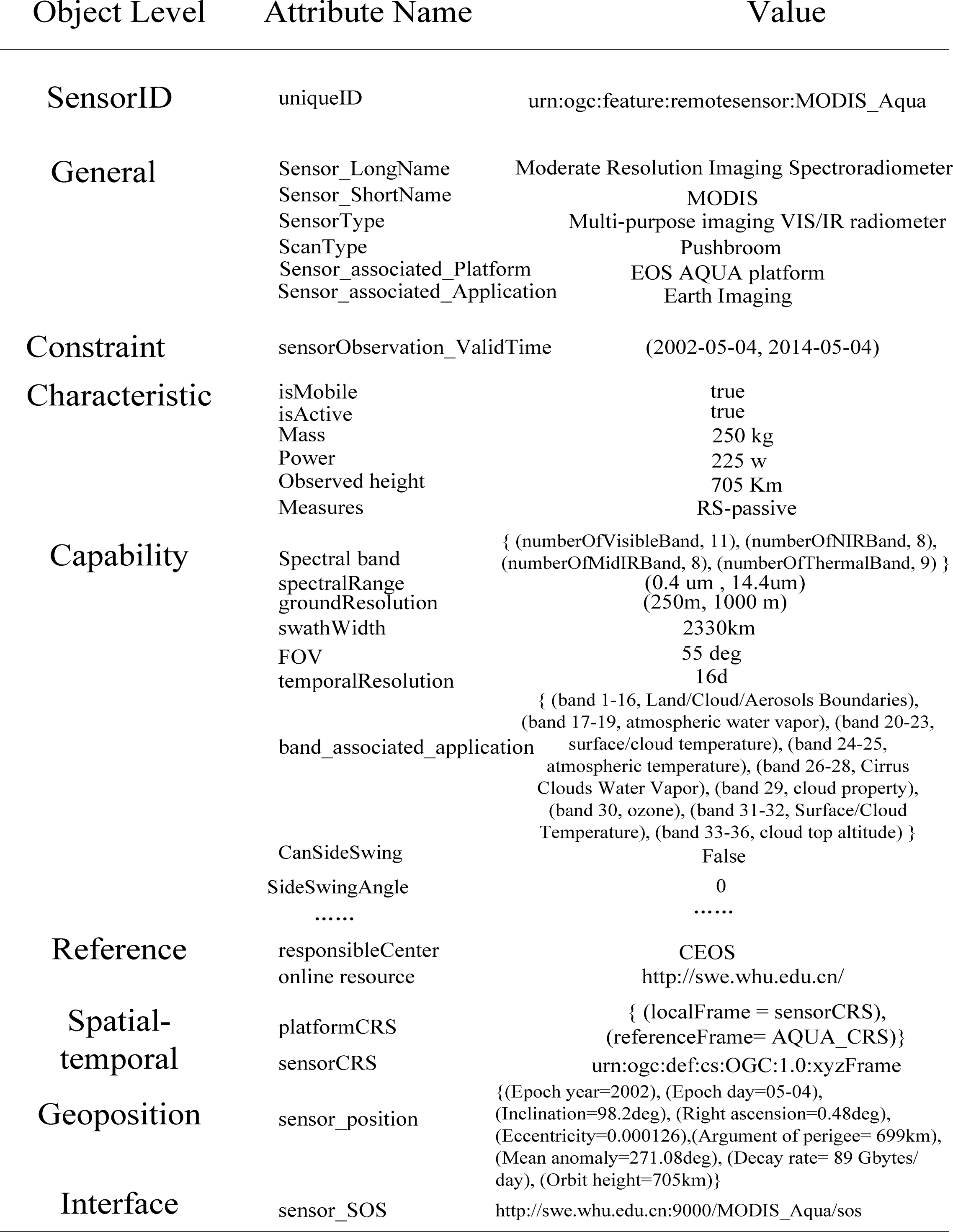
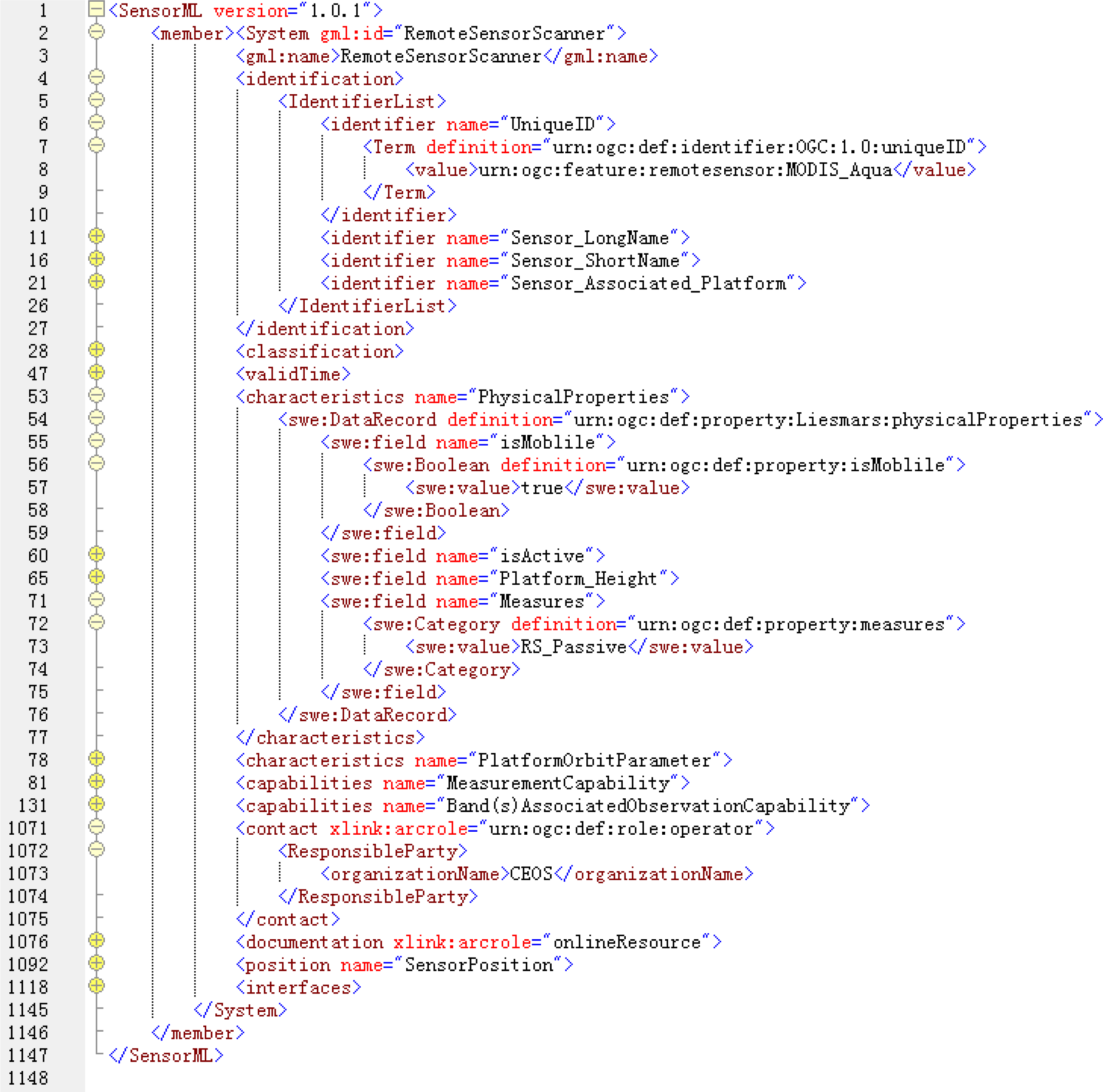
3.1. Scanner SRO_rs Attribute State Information Instance

The Moderate Resolution Imaging Spectroradiometer (MODIS) onboard the AQUA satellite is a pushbroom-type scanner sensor, which plays an important role in EO missions. The object “SensorID” has the meta-attribute “UniqueID” with the value urn:ogc:feature:remotesensor:MODIS_Aqua (Figure 2). In conformity with the attribute description of SRO_rs analyzed in Section 2, AQUA_MODIS SRO_rs should contain the following attribute elements: sensor name, sensor type, resolution, physical quality, application, contact, coordinate reference system, and so on. Each object inside the eight-tuple metadata group enumerates the meta-attributes. For example, the meta-attributes of MD i CP have the following enumerated list.
  • Object subclass Capability ( MD i CP)
  • Instance Variables:
    • Spectral band (set of ordered pairs of “string-integer”)
    • Spectral range (double)
    • Ground resolution (integer)
    • Temporal resolution (integer)
    • Band_associated_application (set of ordered pairs of “string-string”)
    • ………
We adopt SensorML as the carrier to represent the above meta-attributes of the AQUA_MODIS SRO_rs. Figure 3 shows the RA_rs fragment of the AQUA_MODIS SRO_rs.

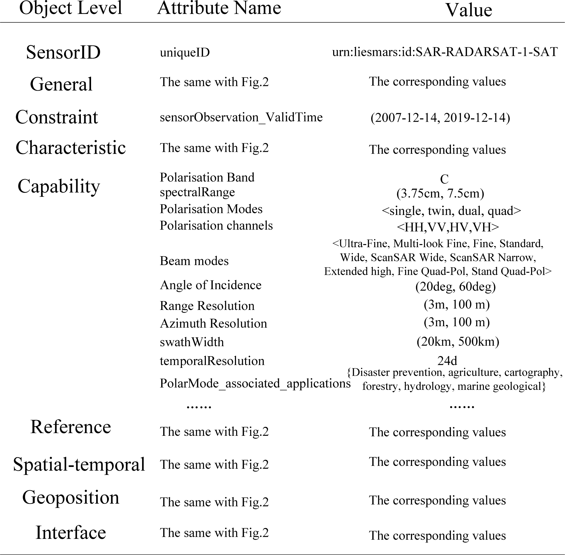
3.2. Radar SRO_rs Attribute State Information Instance

SAR is a microwave instrument that sends pulsed signals to Earth and processes the received reflected pulses. This type of sensor is referred to as a radar sensor. In this study, we consider “RADARSAT-2_SAR” as an example. The SAR onboard RADARSAT-2 is an advanced EO satellite project developed by the Canadian Space Agency and MacDonald, Dettwiler, and Associates Ltd. to monitor environmental changes and support resource sustainability. The platform height of the “RADARSAT-2_SAR” observing system is 798 km; this system is a type of space-borne movable remote sensing system that has a measurement principle of active remote sensing. Compared to “RADARSAT-2_SAR” and “AQUA_MODIS,” the mathematical proposition {“Is_Same_PlatformHeightType” = Yes ∧ “Is_Same_Mobility” = Yes ∧ “Is_Same_Measures” = Yes} returns a “false” value. As shown in Figure 4, the main difference between the two heterogeneous remote SRO_rs instances is that their MD i CP has different attribute variables, whereas the other seven-tuple metadata objects have the same meta-attributes as those of the above scanner SRO_rs but with different meta-attribute values. That is, the “RADARSAT-2_SAR” and the above “AQUA_MODIS” SRO_rs are heterogeneous. The RA of “RADARSAT-2_SAR” is available at the online sensor view module ( http://swe.whu.edu.cn/sensormodel/SensorView.aspx).

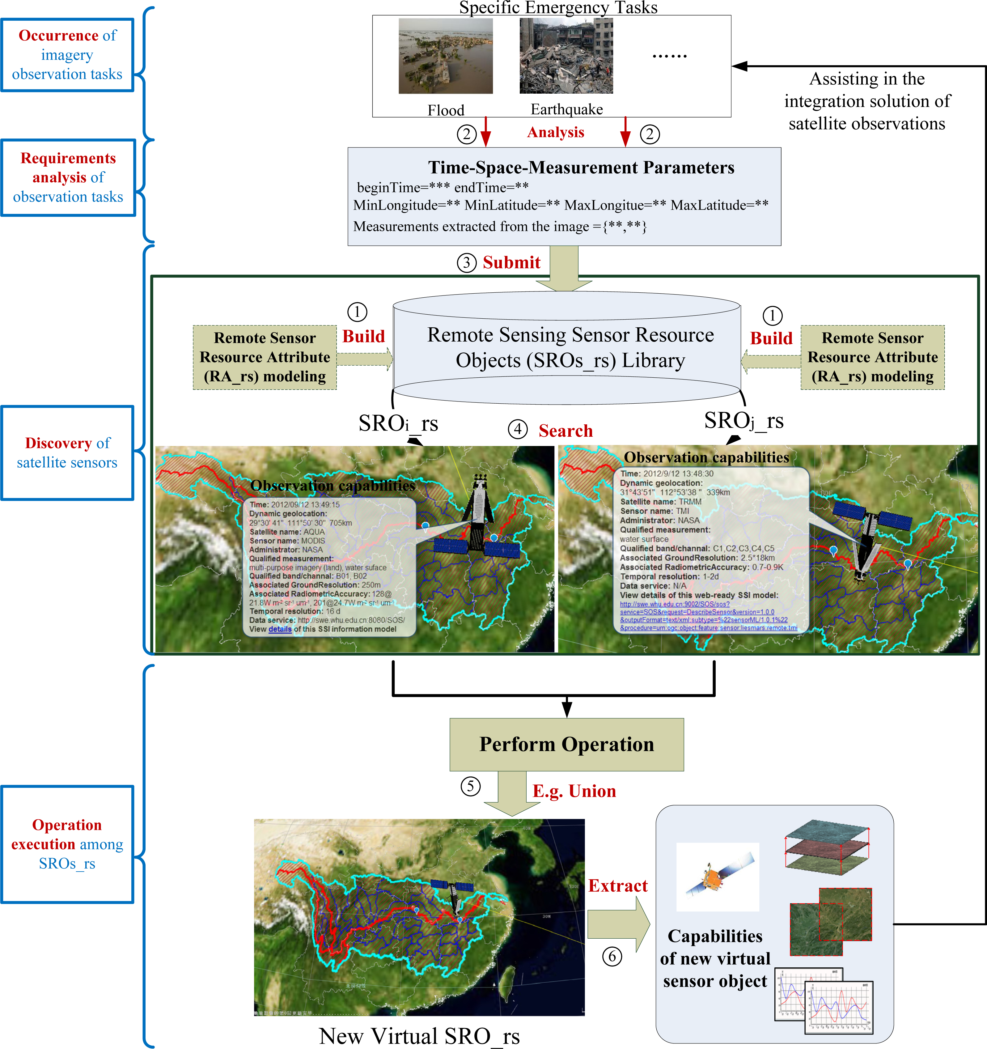
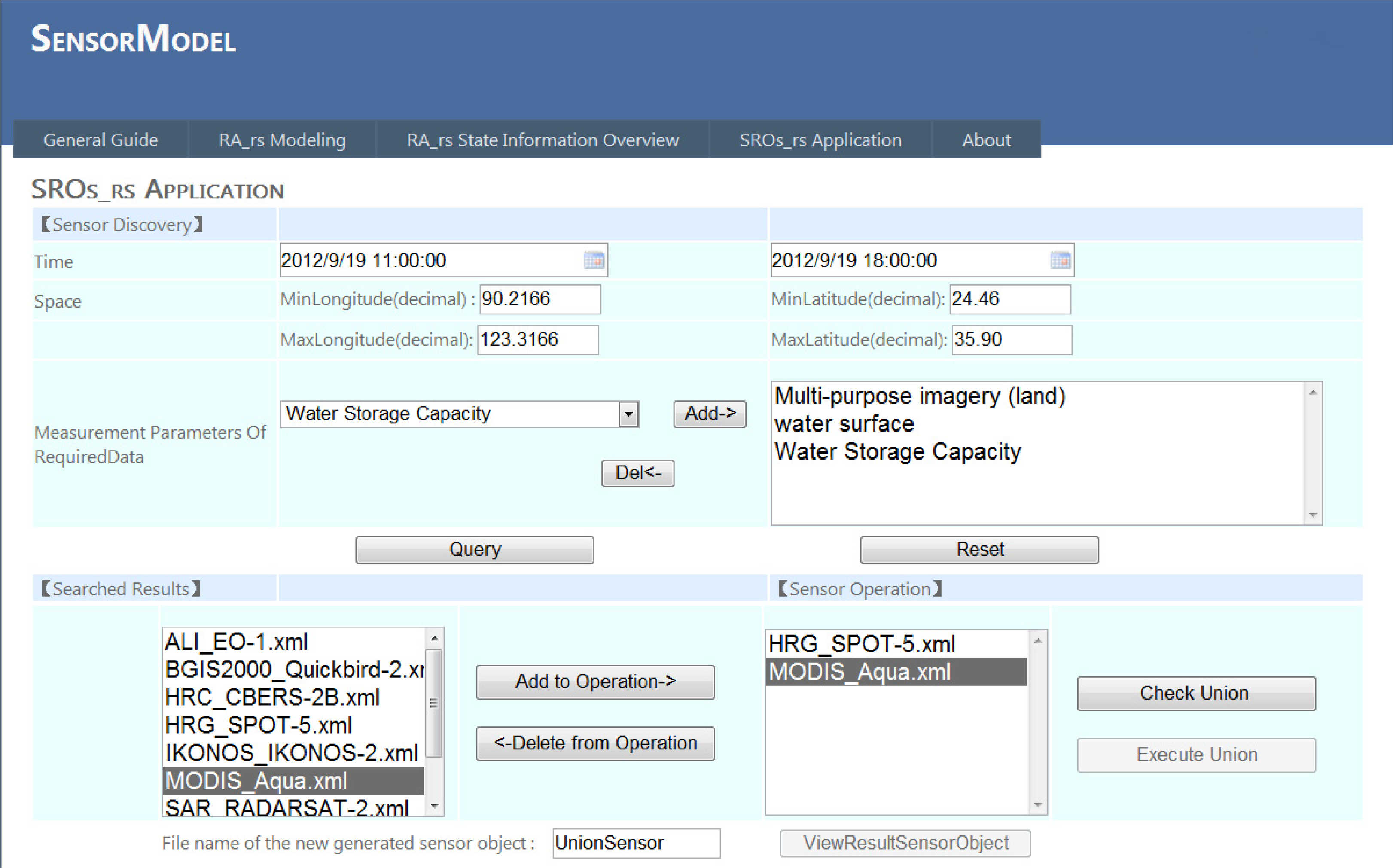
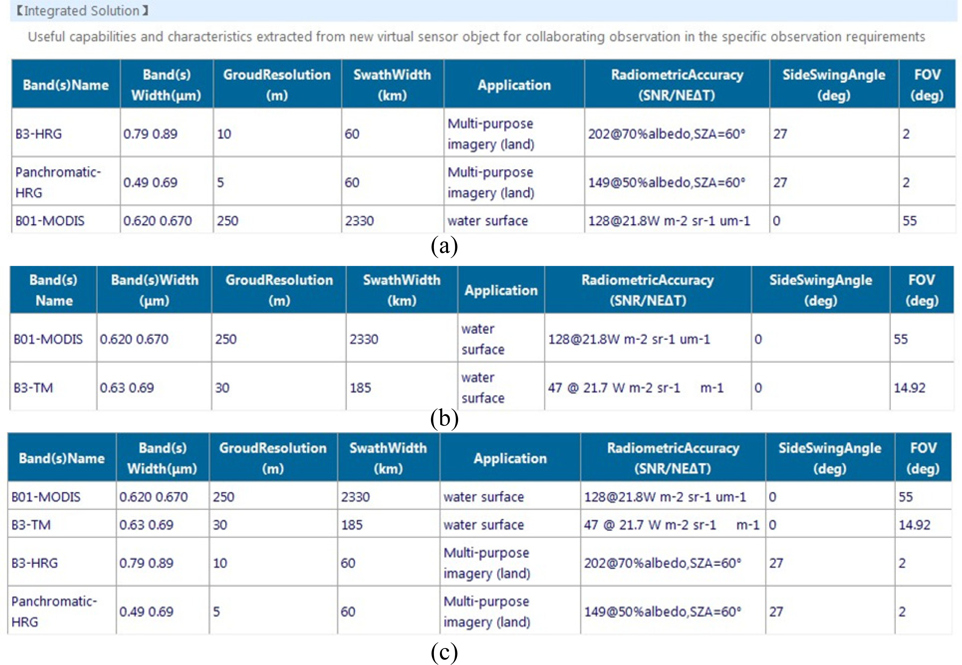
3.3. Object Model Application

SensorModel is an online prototype ( http://swe.whu.edu.cn/SensorModel) developed by our team to provide the rapid construction of the uniform representation of RA_rs for different types of SRO_rs instances and to implement the union operation among different homogeneous satellite SRO_rs instances. The experimental flow to demonstrate the functionality of the proposed model is as follows. First, modelers can rapidly and efficiently build the RA_rs description model by using the online modeling module ( http://swe.whu.edu.cn/SensorModel/SensorModelScanner.aspx); then, the RA_rs libraries are formed. Next, depending on the actual emergency situation, the sensor inquirer inputs the search criteria in the form of “time–space–measurement_parameters_of_required_data” to determine the qualified sensor ( http://swe.whu.edu.cn/SensorModel/SensorOperation.aspx). Thereafter, we select the SRO_rs instances from the searched results to perform the selected operation, where the relations between these sensors should be determined to ascertain whether they are homogeneous or heterogeneous. If they are homogeneous, the selected homogenous operation needs to be executed. Figure 5 shows the four stages of our proposed object model involved in the integration of satellite imagery observation, including the occurrence of imagery observation tasks, requirement analysis of imagery observation tasks, discovery of satellite sensors, and operation execution among SROs_rs. The new virtual SRO_rs generated from selected operation in the last stage has more powerful imagery observation capability which can assist in the integration of satellite observations for the specific emergency task.
In this study, approximately 30 remote sensing satellite sensors, including MODIS_AQUA and HRG_SPOT 5, are described in the experimental library ( http://swe.whu.edu.cn/SensorModel/SensorView.aspx). A hypothetical flood observation in the Yangtze River (24°27′ N to 35°54′ N, 90°13′ E to 122°19′ E) in China is used as the actual application. This location requires an appropriate and timely observation response from the EO satellite sensors. The application of remote sensing technology in flood observation involves the identification of the geographical location of flood water, flood inundation areas, water capacity, and so on. In this study, we select “water surface extraction,” “water storage capacity,” and “multipurpose imagery (land)” as the measurement parameters. On the basis of the proposed model, we conduct a concrete sensor query with the following parametric values: “beginTime = 2012-09-19T11:00:00,” “endTime = 2012-09-19T18:00:00,” “MinLongitude (decimal) = 90.2166,” “MinLatitude (decimal) = 24.45,” “MaxLongitude (decimal) = 122.3166,” “MaxLatitude (decimal) = 35.9,” and “measurement_parameters_of_required_data = {multipurpose imagery (land), water surface, water storage capacity}.”
The proposed model can support the acquisition of suitable sensors by the sensor inquirer. The search results (Figure 6) show the available sensors that meet the specific observation requirements (i.e., “ALI_EO-1,” “MODIS_AQUA,” “HRG_SPOT-5,” “SAR_RADARSAT-2,” and “TM_Landsat-5”) such that selective measurements can be obtained under the given spatial and temporal conditions.
We then select the sensor collection such as “{HRG_SPOT-5, MODIS_AQUA},” “{MODIS_AQUA, TM_Landsat-5},” “{HRG_SPOT-5, MODIS_AQUA, TM_Landsat-5},” and “{SAR_RADARSAT-2, HRG_SPOT-5}” to conduct the union operation. By initially executing “Check Union,” we find that the other three collections are homogeneous, except for “{SAR_RADARSAT-2, HRG_SPOT-5}.” Three new virtual SRO_rs instances are produced by implementing “Execute Union.” Each new RA_rs of the SRO_rs can be viewed by clicking the “ViewResultSensorObject” option. Figures 7a to c show the useful observation capabilities and characteristics extracted from the corresponding new RA_rs.
The sensor inquirer can determine that Band 03, the panchromatic of “HRG_SPOT 5,” and Band 01 of “MODIS_AQUA” can complete the measurements of “multipurpose imagery (land)” and “water surface” (Figure 7a). Band 01 of “MODIS_AQUA” and Band 3 of “TM_Landsat-5” are suitable for the “water surface” measurement (Figure 7b). Band 01 of “MODIS_AQUA” and Band 3 of “TM_Landsat-5” can be used for the “water surface” measurement, whereas Band 3 and the panchromatic of “HRG_SPOT 5” can complete the measurement of “multipurpose imagery (land) (Figure 7c).

4. Discussions

4.1. Feasibility and Versatility of Proposed Object Model

In the proposed model, each remote sensor can be specialized into a concrete SRO_rs according to the sensor type. Each concrete SRO_rs is viewed as an object that has stable modeling units, including SensorID, RA_rs, and RM_rs. The adoption of SensorML as the description framework of RA_rs carefully considers the elements needed in the accessibility and sharing of remote sensing satellite sensors, particularly the observation capabilities. As described in Section 3, different types of remote sensing satellite sensors are encapsulated into the SRO_rs state description instance. In particular, the concept of sensor objects with pertinent operations can be applied to any remote sensor. In this study, each physical remote sensor is viewed as an entity with its own objective attributes and operations. The proposed sensor object model is used for sharing and integrating remote sensing satellite sensors, whereas that of the object-oriented modeling approach is to realize the object management, mutual cooperation, and collaboration of the object system. Therefore, the object-oriented approach is more feasible for building a sensor model for the integration multiple remote sensors than the function-specific sensor modeling standard introduced in Section 1.

4.2. Conducive to Uniform Management and Integration of Multiple Remote Sensing Satellite Sensors and their Observations

The existing tools or applications such as REmote Sensing Planning Tool (RESPT: http://ww2.rshgs.sc.edu/pg_Predict.aspx) and NASA Global Change Master Directory (GCMD) retrieval portal ( http://gcmd.gsfc.nasa.gov/KeywordSearch/Freetext.do?KeywordPath=&Portal=GCMD&Freetext=hyperion&MetadataType=0), which can be used for managing satellite sensors for emergency management, have their own proprietary information descriptions for sensor attribute states. Such tools use different sensor description standards to express the random attributes of sensor objects. Therefore, achieving the uniform sharing and discovery of heterogeneous satellite sensors, particularly the observations, is difficult. RESPT can be used only for the planning of satellite sensors provided by the user. The GCMD retrieval portal is used to discover satellite sensors by using the fuzzy mode of entering “free text” and “filter list” as the query criteria. In this study, we consider the comprehensive state information of fine-grained satellite sensors, including basic sensor identification, physical characteristics, sensor geoposition, and observation capability attributes. By adopting the SensorML as the description framework to encapsulate the defined attributes of remote sensing satellite sensors, the proposed SensorML-based RA_rs can satisfy the scenario wherein the user can uniformly and accurately discover qualified multiple sensors. Furthermore, the sensor inquirer can clearly obtain a sensor integration solution, namely, resolving the question of “sensor-collaborate-with-sensor,” by executing the operation among different SRO_rs instances. For example, the sensor inquirer can determine sensors with the same applications under the same temporal and spatial conditions (Figures 7a to c). Band 3 and the panchromatic of “HRG_SPOT 5” have the same applications. The inquirer considers other additional attributes regarding the capabilities and characteristics of the sensors, such as “RadiometricAccuracy,” to determine further the superior band. On the basis of unique measurements from different sensors, the inquirer can solve the integration solution to determine the bands that can collaborate in completing a specific task (Figure 7a). Band 3 or the panchromatic of “HRG_SPOT 5” can collaborate with Band 01 of “MODIS_AQUA” to complete the measurements of “multipurpose imagery (land)” and “water surface” needed in the flood observations. With regard to an emergency observation task, a lag during decision making can often result in significant losses. Therefore, such tasks usually require accurate and comprehensive responses by immediately discovering and planning a sensor for the observation. Instead of getting confused or ignoring earlier mass satellite sensor information, the sensor inquirer can employ the new SRO_rs for the continuous acquisition of data by leveraging the observation information extracted from the RA_rs of the new virtual SRO_rs.

5. Conclusions

This study introduces a remote sensing satellite sensor object model that comprises SensorID, meta-attribute state, and associated operation method. We exemplify and illustrate the union operation and examine it by using homogeneous remote sensors retrieved within a real-life situation. The results confirm that the model performs as a uniform attribute state information descriptor for sensor discovery. Furthermore, the model can serve as a computable model that uses the union operation, and assist in the integration of multiple satellite sensors during an emergency task.
The future directions of this study are as follows: evolve the mode of the current syntactic matchmaking between specific remote sensing tasks and the database of remote sensor metadata into the semantic mode [41,42]; develop other proposed operations that are suitable for heterogeneous SRO_rs instances to provide a complete information foundation for the integration of different satellite sensors; further improve the proposed prototype SensorModel with the characterization of providing a preliminary status on the quality of discovered sensors.

List of Abbreviations

The following symbols and abbreviated terms are used in this paper.
OMs
Sensor Object Model
SRO
Sensor Resource Object
SensorID
Sensor Identification
RA
Resource Attribute
RM
Resource Method
MD
Metadata
SRO_rs
remote sensing Sensor Resource Object
SRO1_rs
remote sensing Sensor Resource Object 1
SRO'_rs
new remote sensing Sensor Resource Object
OMrs
remote sensing Sensor Object Model
RA_rs
remote sensing sensor Resource Attribute
RA1_rs
remote sensing sensor Resource 1 Attribute
RM_rs
remote sensing sensor Resource Method
MD i G
General Metadata group
MD i CT
Characteristic Metadata group
MD i CP
Capability Metadata group
MD i C
Constraint Metadata group
MD i GP
Geoposition Metadata group
MD i ST
Spatial-Temporal Metadata group
MD i I
Interface Metadata group
MD i R
Reference Metadata group

Acknowledgments

This work was supported by grants from the National Basic Research Program of China (973 Program) (no. 2011CB707101), National High Technology Research and Development Program of China (863 Program) (no. 2013AA01A608), National Nature Science Foundation of China (NSFC) program (nos. 41171315, 41023001, and 41021061), Program for New Century Excellent Talents in University under Grant NCET-11-0394, Program for New Teachers’ Fund for Doctor Stations of Ministry of Education(no.20130145120013).

Author Contributions

Chuli Hu and Nengcheng Chen conceived and designed the project. Chuli Hu and Jia Li performed the experiments. Chuli Hu and Jia Li wrote the paper. Chuli Hu, Jia Li and Qingfeng Guan reviewed and edited the manuscript. All authors read and approved the manuscript.

Conflicts of Interest

The authors declare no conflict of interest.

References

  1. Kambur, D.; Roantree, M.; Murphy, J. An object model for sensor data integration. J. Object Technol 2008, 7, 97–117. [Google Scholar]
  2. Luo, R.C.; Chang, C.C.; Lai, C.C. Multisensor fusion and integration: Theories, applications, and its perspectives. IEEE Sens. J 2011, 11, 3122–3138. [Google Scholar]
  3. Bröring, A. Automated On-the-fly Integration of Geosensors with the Sensor Web. Ph.D. Dissertation,. University of Twente: Enschede, The Netherlands, 2012. [Google Scholar]
  4. Xiong, N.; Svensson, P. Multi-sensor management for information fusion: issues and approaches. Inf. Fusion 2002, 3, 163–186. [Google Scholar]
  5. Jenkins, K.L.; Castanon, D. Information-Based Adaptive Sensor Management for Sensor Networks. Proceedings of the American Control Conference (ACC), San Francisco, CA, USA, 29 June–1 July 2011; pp. 4934–4940.
  6. Kreucher, C.; Kastella, K.; Hero, A.O., III. Information based sensor management for multitarget tracking. Proc. SPIE 2003, 5204, 481. [Google Scholar]
  7. Quartulli, M.; Datcu, M. Information fusion for scene understanding from interferometric SAR data in urban environments. IEEE Trans. Geosci. Remote Sens 2003, 41, 1976–1985. [Google Scholar]
  8. Aanaes, H.; Sveinsson, J.R.; Nielsen, A.A.; Bovith, T.; Benediktsson, J.A. Model-based satellite image fusion. IEEE Trans. Geosci. Remote Sens 2008, 46, 1336–1346. [Google Scholar]
  9. Bröring, A.; Echterhoff, J.; Jirka, S.; Simonis, I.; Everding, T.; Stasch, C.; Liang, S.; Lemmens, R. New generation sensor web enablement. Sensors 2011, 11, 2652–2699. [Google Scholar]
  10. Di, L. Geospatial sensor web and self-adaptive Earth predictive systems (SEPS). Proceedings of the Earth Science Technology Office (ESTO)/Advanced Information System Technology (AIST) Sensor Web Principal Investigator (PI) Meeting, San Diego, CA, USA, 23–24 February 2007; pp. 1–4.
  11. Blaschke, T.; Hay, G.J.; Weng, Q.; Resch, B. Collective sensing: Integrating geospatial technologies to understand urban systems—An overview. Remote Sens 2011, 3, 1743–1776. [Google Scholar]
  12. Botts, M. OpenGIS Sensor Model Language (SensorML) Implementation Specification; Open Geospatial Consortium: Wayland, MA, USA, 2007. [Google Scholar]
  13. Durrant-Whyte, H.F. Sensor models and multisensor integration. Int. J. Robot. Res 1988, 7, 97–113. [Google Scholar]
  14. Foerster, T.; Bröring, A.; Jirka, S.; Müller, J. Sensor web and geoprocessing services for pervasive advertising. Proceedings of the 2nd Workshop on Pervasive Advertising—In Conjuction with Informatik 2009, Lübeck, Germany, 4–7 September 2009; pp. 88–99.
  15. Di, L.; Moe, K.; Yu, G. Metadata requirement analysis for the emerging Sensor Web. Int. J. Digit. Earth 2009, 2, 3–17. [Google Scholar]
  16. Chen, N.; Hu, C. A Sharable and interoperable meta-model for atmospheric satellite sensors and observations. IEEE J. Sel. Top. Appl. Earth Obs. Remote Sens 2012, 5, 1519–1530. [Google Scholar]
  17. Simonis, I.; Echterhoff, J. GEOSS and the Sensor Web; GEOSS Sensor Web Workshop Report; Publisher: Geneva, Switzerland, 2008. [Google Scholar]
  18. Rob, S. A comparison of the object-oriented and process paradigms. Proceedings of the 1986 SIGPLAN Workshop on Object-Oriented Programming, Yorktown Heights, NY, USA, October 1986.
  19. Ramsin, R.; Paige, R.F. Process-centered review of object oriented software development methodologies. ACM Comput. Surv 2008, 40, 1–89. [Google Scholar]
  20. Yang, Q.; Butler, C. An object-oriented model of measurement systems. IEEE Trans. Instrum. Meas 1988, 47, 104–107. [Google Scholar]
  21. Rumbaugh, J.R.; Blaha, M.R.; Lorensen, W.; Eddy, F.; Premerlani, W. Object-Oriented Modeling and Design; Prentice-hall: Upper Saddle River, NJ, USA, 1990. [Google Scholar]
  22. Clark, D. Beginning C# Object-Oriented Programming; Apress: New York, NY, USA, 2013. [Google Scholar]
  23. Bordogna, G.; Pasi, G.; Lucarella, D. A fuzzy Object-Oriented Data model for managing vague and uncertain information. Int. J. Intell. Syst 1999, 14, 623–651. [Google Scholar]
  24. Lee, K.B.; Song, E.Y. Object-oriented application framework for IEEE 1451.1 standard. Ieee Trans. Instrum. Meas 2005, 54, 1527–1533. [Google Scholar]
  25. Neuhaus, J.R. An object-oriented sensor and sensor system design. Proceedings of the AIAA Modeling and Simulation Technologies Conference, Montreal, QC, Canada, 6–9 August 2001.
  26. Di, L.; Kresse, W.; Kobler, B. The current status and future plan of the ISO 19130 project. Proceedings of the XXth ISPRS Congress, Istanbul, Turkey, 12–23 July 2004.
  27. Matsumoto, S. Echonet: A home network standard. IEEE Pervasive Comput 2010, 9, 88–92. [Google Scholar]
  28. Chen, N.; Hu, C.; Chen, Y.; Wang, C.; Gong, J. Using SensorML to construct a geoprocessing e-Science workflow model under a sensor web environment. Comput. Geosci 2012, 47, 119–129. [Google Scholar]
  29. Tang, S.-M.; Yeh, F.-L.; Wang, Y.-L. An efficient algorithm for solving the homogeneous set sandwich problem. Inf. Process. Lett 2001, 77, 17–22. [Google Scholar]
  30. Chen, C.; Helal, S. Sifting through the jungle of sensor standards. IEEE Pervasive Comput 2008, 7, 84–88. [Google Scholar]
  31. Object-Oriented approach. Available online: http://en.wikipedia.org/wiki/Class_diagram (accessed on 3 July 2013).
  32. ISO 19130–2 standard. Available online: http://www.iso.org/iso/iso_catalogue/catalogue_ics/catalogue_detail_ics.htm?ics1=35&ics2=240&ics3=70&csnumber=56113 (accessed on 3 July 2013).
  33. Liu, Y.; Hill, D.; Rodriguez, A.; Marini, L.; Kooper, R.; Myers, J.; Wu, X.; Minsker, B. A new framework for on-demand virtualization, repurposing and fusion of heterogeneous sensors. Proceedings of the International Symposium on Collaborative Technologies and Systems, 2009, CTS '09, Baltimore, MD, USA, 18–22 May 2009; pp. 54–63.
  34. Hill, D.J.; Liu, Y.; Marini, L.; Kooper, R.; Rodriguez, A.; Futrelle, J.; Minsker, B.S.; Myers, J.; McLaren, T. A virtual sensor system for user-generated, real-time environmental data products. Environ. Model. Softw 2011, 26, 1710–1724. [Google Scholar]
  35. Malewski, C.; Simonis, I.; Terhorst, A.; Bröring, A. StarFL–A modularised metadata language for sensor descriptions. Int. J. Digit. Earth 2012. [Google Scholar] [CrossRef]
  36. How Many Satellites Are Orbiting the Earth? Available online: http://www.studymode.com/essays/How-Many-Satellites-Are-Orbiting-The-1427572.html (accessed on 14 October 2013).
  37. Jirka, S.; Bröring, A.; Stasch, C. Discovery mechanisms for the sensor web. Sensors 2009, 9, 2661–2681. [Google Scholar]
  38. Terhorst, A.; Moodley, D.; Simonis, I.; Frost, P.; Mcferren, G.; Roos, S.; Bergh, F. Using the Sensor Web to Detect and Monitor the Spread of Vegetation Fires in Southern Africa. In GeoSensor Networks; Nittel, S., Labrinidis, A., Stefanidis, A., Eds.; Lecture Notes in Computer Science; Springer: Berlin/Heidelberg, Germany, 2008; Volume 4540, pp. 239–251. [Google Scholar]
  39. NGA Standardization Document, Pushbroom/Whiskbroom Sensor Model Supporting Precise Geopositioning. 2009, p. 89. Available online: www.gwg.nga.mil/documents/csmwg/NGA.SIG.0003.1.0.htm (accessed on 03 January 2014).
  40. NGA Standardization Document, Spotlight Synthetic Aperture Radar (SAR) Sensor Model Supporting Precise Geopositioning. 2010, p. 86. Available online: http://www.gwg.nga.mil/csmwg_documents.php (accessed on 03 January 2014).
  41. Bröring, A.; Maué, P.; Janowicz, K.; Nüst, D.; Malewski, C. Semantically-enabled sensor plug & play for the sensor web. Sensors 2011, 11, 7568–7605. [Google Scholar]
  42. Malewski, C.; Bröring, A.; Maué, P.; Janowicz, K. Semantic matchmaking & mediation for sensors on the sensor web. IEEE J. Sel. Top. Appl. Earth Obs. Remote Sens 2013. [Google Scholar] [CrossRef]
Figure 1. Conceptual level of the sensor object model (blue font are the corresponding instructions).
Remotesensing 06 00677f1
Figure 2. Assignment of meta-attribute values for the AQUA_MODIS SRO_rs.
Remotesensing 06 00677f2
Figure 3. Sample of AQUA_MODIS SRO_rs representation.
Remotesensing 06 00677f3
Figure 4. The assignment of meta-attribute values for RADARSAT-2_SAR SRO_rs.
Remotesensing 06 00677f4
Figure 5. The stages of our proposed object model involved in the integration of satellite imagery observation (the marked numbers represent the detailed experimental flows).
Remotesensing 06 00677f5
Figure 6. Sensor application based on the proposed model.
Remotesensing 06 00677f6
Figure 7. Useful observation information extracted from the corresponding new RS_rs of SRO_rs.
Remotesensing 06 00677f7
Table 1. Seven metadata groups’ attributes of remote sensing satellite sensors.
Metadata GroupMain attribute State Elements
MD i Gkeyword, sensor ID, sensor type, sensor name, sensor_associated_platform, platform type, platformID, platform name, Sensor_associated_application
MD i Csensor observation valid time, sharing level of sensor, responsible center,
MD i CTmobility, measures, height, mass, power, dimension,
MD i RSensor online resources’ URL
MD i IWeb service interface
MD i STPlatformCRS, SensorCRS
MD i GPPlatformOribt, platformDynamics
Table 2. MD i CP for a specific type of remote sensing satellite sensors.
Sensor CapabilitiesBasic ObservationObservation Geolocation
(from ISO 19130 Series)

Sensor TypeMD Group
Camera Sensorframe MD i CPBand(s)Name, Band(s)Width, GroundResolution, Band(s)AssociatedApplication, NumberOfSpectralBand, GroundResolutionRange, SpectralRange, TemporalResolution RadiometricAccuracySensor Rotation About X/Y/Z-axis, Sensor Focal
Length, Column Spacing, Row Spacing, Various distortions
filmNO developing in 19130 series
Scanner SensorPushbroom MD i CPBand(s)Name, Band(s)Width, GroundResolution, Band(s)AssociatedApplication, NumberOfSpectralBand, GroundResolutionRange, SpectralRange, TemporalResolution RadiometricAccuracyRow Spacing, Collection Start/Stop Time, Sensor Focal Length, FOV, IFOV, Maximum Scan Angle, Pushbroom scan duration, Whiskbroom scan duration, Whiskbroom pixel scan duration, SwathWidth, CanSideSwing, SideSwingAngle, platform Roll, Pitch, yaw
whiskbroom
Radar SensorSAR MD i CPMode(s)Name, IncidentAngle, RangeResolution, AzimuthResolution, NumberOfMode, MicrowaveFrequency, PolarizationBand, GroundResolutionRange, TemporalResolution RadiometricAccuracySwathWidthRange Line spacing, Sample spacing, Output plane unit vectors, Scene center point (SCP), Scene center point line/sample, Antenna Reference Point (ARP), Position-Velocity Correlation Coefficient, Position-Velocity Decorrelation Rate
LiDARNO developing in 19130 series
Table 3. Logical structure of remote sensing sensor resource object.
SRO_rs
SensorIDRA_rsRM_rs
SensorIDMDiUnion (MDi)Intersection (MDi)Difference (MDi)Product (MDi)Join (MDi)
UniqueIDiA_1A_2A_3A_n
A_1 is the first attribute of the metadata node MDi. A_n represents the Nth meta-attribute. Every SRO_rs has a unique ID and has five operations associated with other SRO_rs instances.
Table 4. Earth Observation (EO) sensor classification and analysis of different meta-attribute elements.
TypesClassification perspectiveClassification ValueInstructions about the difference of the meta-attribute
Traditional EOPlatformHeightSpace
  • The orbit, dynamic observed boundingbox attributes of space/aviation sensor do not exist in ground sensor
  • And so on
Aviation
ground
OGC Sensor Model LanguageMobilityFixed
  • Velocity of mobile platform does not exist in fixed platform
  • The polarization mode and operating frequency attribute of active sensors does not exist in passive sensors
  • And so on
Mobile
MeasuresIn-situ
Remoteactive
passive

