Article

Intercomparison of Ozone Vertical Profile Measurements by Differential Absorption Lidar and IASI/MetOp Satellite in the Upper Troposphere–Lower Stratosphere

by
Sergey I. Dolgii
1,
Alexey A. Nevzorov
1,
Alexey V. Nevzorov
1,
Oleg A. Romanovskii
1,2,* and
Olga V. Kharchenko
1
1
V.E. Zuev Institute of Atmospheric Optics, 1 Academician Zuev Square, Tomsk 634055, Russia
2
Department of Innovative Technologies, National Research Tomsk State University, 36 Lenin Avenue, Tomsk 634050, Russia
*
Author to whom correspondence should be addressed.
Remote Sens. 2017, 9(5), 447; https://doi.org/10.3390/rs9050447
Submission received: 10 February 2017 / Revised: 24 April 2017 / Accepted: 27 April 2017 / Published: 8 May 2017
(This article belongs to the Special Issue Remote Sensing of Atmospheric Pollution)

Abstract

:
This paper introduces the technique of retrieving the profiles of vertical distribution of ozone considering temperature and aerosol correction in DIAL sounding of the atmosphere. The authors determine wavelengths, which are promising for measurements of ozone profiles in the upper troposphere–lower stratosphere. An ozone differential absorption lidar is designed for the measurements. The results of applying the developed technique to the retrieval of the vertical profiles of ozone considering temperature and aerosol correction in the altitude range 6–15 km in DIAL sounding of the atmosphere confirm the prospects of ozone sounding at selected wavelengths of 341 and 299 nm with the proposed lidar. The 2015 ozone profiles retrieved were compared with satellite IASI data and the Kruger model.

Graphical Abstract

1. Introduction

Laser remote sounding techniques with the use of the lidar (Light Detection and Ranging) technology are widely used for the study and monitoring of the atmosphere. Among the techniques used for measuring the spatial distribution of the concentration of an atmospheric gas, the most sensitive is the differential absorption method (DIAL).The essence of the method is that radiation is transmitted in the atmosphere simultaneously at two wavelengths: one of them (λon) is on a strong absorption line or band of the gas to be measured and another (λoff) is off the absorption line and is weakly absorbed in the atmosphere or not absorbed at all. At present, DIAL sounding of trace atmospheric gases including ozone, is implemented [1,2,3].
Laser sounding of the ozonosphere became routine at some observatories since the second half of the 1980s [4,5,6,7]. It allows data to be received on vertical distribution of ozone (VDO), which successfully supplement similar data received by in situ methods with the use of ozonesondes, rockets, or satellites (TOMS, SAGE-II, TERRA, MetOp, etc.).
It should be noted that the profiles of IASI/MetOp-measured atmospheric ozone concentrations were earlier compared with the profiles measured in the troposphere with compact airborne lidars, ozone sondes, ground-based lidars, and Brewer–Dobson spectrophotometers [8,9,10].
Laser sounding of the vertical distribution of stratospheric ozone has been carried out at the Siberian Lidar Station (SLS) of Institute of Atmospheric Optics SB RAS (Tomsk, 56.5°N, 85.0°E) since 1989. A long period of lidar observations of stratospheric ozone has shown that the most important part of the ozonosphere for the study is located in the lower stratosphere, where ozone is affected by the dynamic factor. DIAL measurements of ozone profiles in different altitude ranges with different ozone content are carried out at different combinations of wavelengths [4,5,6,7].
The aims of this work are the development of an algorithm and program for VDO retrieval with temperature and aerosol correction; selection of the VDO sounding wavelengths; the design of an ozone lidar; and analysis of the measurement results, including the comparison between the ozone vertical profiles retrieved from the ground-based DIAL lidar system data and the profiles retrieved from IASI/MetOp data.

2. Methods

2.1. Selection of Wavelengths

Lidar measurements of VDO are carried out on the basis of the method of the differential absorption of the backscattered laser radiation in the ultraviolet spectral range 200–370 nm (Hartley–Huggins band) [11]. In practice, several pairs of wavelengths can be implemented in ozone lidars with the help of different lasers. Table 1 represents the specifications of some lidars used for ozone measurements and operating at different combinations of wavelengths.
More than 85% of atmospheric ozone is located in the stratosphere. To measure the much smaller concentrations of tropospheric ozone, sounding wavelengths should be selected from the short wavelength range, closer to the ozone absorption band center, to increase the concentration sensitivity of the method. In this spectral range, the absorption cross-section σ is several times larger than that for wavelengths used in stratospheric measurements (e.g., σ299 = 4.4 × 10⁻¹⁹ cm2 for the wavelength λon = 299 nm and σ308 = 1.4 × 10⁻¹⁹ cm2 for λon = 308 nm).
KrF laser radiation (248 nm) or the fourth harmonics of an Nd:YAG laser (266 nm) is usually used for measurements of tropospheric ozone, in combination with a technique based on the stimulated Raman scattering (SRS) in H2, D2, СО2, and other gases [4,5,7]. The most common are hydrogen and deuterium. Table 2 represents possible sets of wavelengths that correspond to the first, second, and third Stokes (C) frequencies of SRS conversion in H2, D2, and СО2.
Different wavelength combinations are used in practice in different altitude ranges in the troposphere and lower stratosphere. Thus, the wavelength pairs 289/316 and 287/299 nm allow measurements of ozone profiles up to altitudes of about 10 km [4,5]; the pair 292/319 nm, up to 14–16 km [4]; the pairs 277/313 and 292/313 nm, up to altitudes of 8–12 and 15 km, respectively [7].
We have estimated possibilities of the vertical ozone profile sounding in the upper troposphere–lower stratosphere at the wavelength pair 299/341 nm. During the calculations, actual lidar parameters were used: radiation energy of 20 mJ at both wavelengths, pulse repetition frequency of 15 Hz, receiving mirror diameter of 0.5 m, signal accumulation time of 1.5 h. To determine the transmitter–receiver efficiency, actual values of transmittance of optical elements of spectral selection and of efficiency of photomultiplier tubes (PMTs) were used; noises were taken from actual measurements. The calculations have shown that these wavelengths allow the sounding up to about 22 km (the ozone maximum is located in the altitude range 19–21 km in Tomsk) and ozone measurements in the troposphere. The ozone concentration error is within 4–10% limits up to altitudes of about 20 km.
The sounding altitude maximum is determined, first, by the range of signal detection at λon, which is always shorter than the range of signal detection at λoff due to stronger ozone absorption. In view of this, λon = 299 nm is preferable to 277 or 292 nm. In addition, wavelengths of 299 and 341 nm are implemented in one sounding beam (from one laser source in one SRS cell), in contrast to, e.g., the 292/313 nm pair (see Table 2).
A system on the basis of a SRS cell filled with hydrogen is cheaper than with deuterium.
Thus, the wavelength pair 299/341 nm is of higher information content for VDO measurements in the upper troposphere–lowerstratosphere (5–22 km altitude range).

2.2. Theoretical Base of the VDO Retrieval

Initial equations for the calculation of the ozone concentration during DIAL lidar sounding of the atmosphere have the form
N o n ( H ) = c [ β o n a ( H ) + β o n m ( H ) ] exp [ 2 0 H α o n a ( H ) + α o n m + k o n n ( H ) ]
N o f f ( H ) = c [ β f f a ( H ) + β o f f m ( H ) ] exp [ 2 0 H α o f f a ( H ) + α o f f m + k o f f n ( H ) ]
where N(H) is the echo-signal recorded at corresponding wavelengths (on at an absorption line and off out of the absorption line), C is the instrumental constant, α a is the aerosol extinction coefficient, β a is the aerosol backscattering coefficient, k is the absorption cross-section of ozone, n(H) is the ozone concentration.
Let Equation (1) be divided by Equation (2):
N o f f ( H ) N o n ( H ) = β o f f a ( H ) + β o f f m ( H ) β o n a ( H ) + β o n m ( H ) exp { 2 0 H [ α o f f a ( H ) α o n a ( H ) ] d H } exp { 2 0 H [ α o f f m ( H ) α o n m ( H ) ] d H } exp { 2 0 H [ k o f f ( H ) k o n ( H ) ] n ( H ) d H }
where k o n ( H ) and k o f f ( H ) are the absorption coefficients and are off the ozone absorption line, dependent on the temperature.
Let us transform Equation (3) to the form
ln { N o f f ( H ) N o n ( H ) [ β o f f a ( H ) + β o f f m ( H ) β o n a ( H ) + β o n m ( H ) ] } = 2 0 H [ α o f f a ( H ) α o n a ( H ) ] d H 2 0 H [ α o f f m ( H ) α o n m ( H ) ] d H 2 0 H [ k o f f ( H ) k o n ( H ) ] n ( H ) d H
and derive Equation (4):
d d H ln { N o f f ( H ) N o n ( H ) [ β o f f a ( H ) + β o f f m ( H ) β o n a ( H ) + β o n m ( H ) ] } = 2 [ α o f f a ( H ) α o n a ( H ) ] 2 [ α o f f m ( H ) α o n m ( H ) ] 2 [ k o f f ( H ) k o n ( H ) ] n ( H ) .
Then
2 [ k o f f ( H ) k o n ( H ) ] n ( H ) = d d H ln { N o f f ( H ) N o n ( H ) [ β o f f a ( H ) + β o f f m ( H ) β o n a ( H ) + β o n m ( H ) ] } + 2 [ α o f f a ( H ) α o n a ( H ) ] + 2 [ α o f f m ( H ) α o n m ( H ) ] .
The final equation for the ozone concentration is derived with the use of mathematical transformation
n ( H ) = 1 k o n ( H ) k o f f ( H ) A { d d H ln [ N o f f ( H ) N o n ( H ) ] B d d H ln [ β o f f a ( H ) + β o f f m ( H ) β o n a ( H ) + β o n m ( H ) ] C 2 [ α o f f a ( H ) α o n a ( H ) ] D 2 [ α o f f m ( H ) α o n m ( H ) ] F }
or
n ( H ) = A { B C D F } .
Actual variations in the air temperature can cause variations in the ozone absorption cross-section, which results in systematic errors in VDO retrieval. Therefore, it is reasonable to carry out a correction to the temperature dependence kon(H,T), koff(H,T) in the algorithm for VDO retrieval.
A model of the behavior of ozone absorption cross-sections, presented in Table 3 and based on data from [18,19], was used in the technique.
The absorption coefficients k o n ( H ) and k o f f ( H ) are used in term A of Equation (6). Real temperature variations in the atmosphere can significantly change the ozone absorption coefficient. Therefore, it is reasonable to use the correction to the temperature dependence k o n ( H , T ) , k o f f ( H , T ) in the VDO retrieval algorithm such that A takes the form
А = K299(Н,Т) − K341(Н,Т) = (5.8815Е−16) − (1.1538Е−17)·(Т(Н) − 273)
+ (9.0281Е−20)·(Т(Н) − 273)2 − (3.5194Е−22)·(Т(Н) − 273)3
+ (6.8356Е−25)·(Т(Н) − 273)4 − (5.2918Е−8)·(Т(Н) − 273)5,
where Т(Н)–is the model Kelvin temperature distributed with altitude.
Let us consider term С in Equation (6):
C = d d H ln [ β o f f a ( H ) + β o f f m ( H ) β o n a ( H ) + β o n m ( H ) ]
and transform it to the form
β o f f a ( H ) + β o f f m ( H ) β o n a ( H ) + β o n m ( H ) = β o f f a ( H ) + β o f f m ( H ) β o f f m ( H ) R o f f m ( H ) = 1 R o f f ( H ) { β o n a ( H ) β o f f m ( H ) + β o n m ( H ) β o f f m ( H ) } = 1 R o f f ( H ) { ( λ o f f λ o n ) x β o f f a ( H ) β o f f m ( H ) + ( λ o f f λ o n ) 4 } = 1 R o f f ( H ) ( λ o f f λ o n ) x [ R o f f ( H ) 1 ] + 1 R o f f ( H ) ( λ o f f λ o n ) 4 = ( λ o f f λ o n ) x [ 1 1 R o f f ( H ) ] + 1 R o f f ( H ) ( λ o f f λ o n ) 4 ,
where, at the corresponding wavelengths λ (on at an absorption line and off out of the absorption line), Roff(H) is the real distribution of the scattering ratio, x is the parameter that characterizes the particle size, βαoff(H) is the aerosol backscattering coefficient, βmoff(H) is the molecular backscattering coefficient.
From the equalities β o f f m ( H ) β o f f m ( H ) = ( λ o f f λ o n ) 4 and β o f f a ( H ) β o f f a ( H ) = ( λ o f f λ o n ) x , one can find
β o n a ( H ) = ( λ o f f λ o n ) x β o f f a ( H )
Finally,
C = d d H { ln ( λ o f f λ o n ) x [ 1 1 R o f f ( H ) ] + 1 R o f f ( H ) ( λ o f f λ o n ) 4 }
Now consider term D in Equation (6). Since
α a = b β a ,   i.e. ,   α a ( H ) = b β a ( H )
then
D = 2 0.04 [ β o f f a ( H ) β o n a ( H ) ]
Using β o n a ( H ) = ( λ o f f λ o n ) x β o f f a ( H ) and β o f f a ( H ) = [ R o f f ( H ) 1 ] β o f f m ( H )
D = 2 0.04 { β o f f a ( H ) [ 1 ( λ o f f λ o n ) x ] } = 2 0.04 { [ R o f f ( H ) 1 ] β o f f m ( H ) [ 1 ( λ o f f λ o n ) x ] }
Let us also transform term F in Equation (6) using the relations α o n m ( H ) α o f f m ( H ) = ( λ o f f λ o n ) 4 and α o f f m = 3 8 π 0.119 β j f f m ( H ) :
F = 2 0.119 α o f f m [ 1 α o n m ( H ) α o f f m ( H ) ] = 2 0.119 β o f f m ( H ) [ 1 ( λ o f f λ o n ) 4 ]
Aerosol scattering exceeds molecular scattering by several times in the case of high atmospheric aerosol content, which significantly distorts ozone profiles retrieved under unconsidered scattering and attenuating properties of the atmosphere at the sounding wavelengths. In the algorithm for VDO retrieval described, the aerosol correction is considered in the Equations (9) and (15) by means of introduction of a real distribution of the scattering ratio Roff(H), while VDO in the usual, undisturbed atmosphere can be calculated at Roff(H) = 1.
The vertical profile of the backscattering coefficient β π a ( H ) is derived from laser sounding data. The coefficient decreases with an increase in altitude. For clearer representation of aerosol stratification, the scattering ratio
R ( H )   =   [ β π a ( H ) + β π м ( H ) ] / β π м ( H )
is used, where β π м ( H ) is the molecular backscattering coefficient.

2.3. Software for VDO Retrieval

Software for altitude ozone profile retrieval from laser sounding data developed on the basis of the above algorithm (see the block diagram in Figure 1) allows:
  • Reading the lidar data;
  • Recording the retrieval results in ASCII format;
  • Moving average smoothing of lidar signals;
  • Temperature and aerosol correction;
  • Smoothing of the VDO retrieval results.
To decrease the retrieval errors, the temperature correction of ozone absorption coefficients is used in the software. A high aerosol concentration in the 0–20 km altitude range should be considered during lidar signal retrieval when sounding at 272/289 nm and 299/341 nm wavelengths; therefore, aerosol correction is considered in the software. Model seasonal (winter and summer) midlatitude values of altitude distributions of the temperature and molecular backscattering coefficient have been introduced in the software for calculations.
Linear smoothing is used in the software for both input lidar data and retrieval results. The linear smoothing (moving average smoothing) is a well-known technique and is widely used in processing of experimental data in different fields of natural sciences. The linear smoothing is a special case of numerical filtering of signals with random errors using a rectangular window and unit weight coefficients.
The technique and software developed were used for VDO retrieval in the upper stratosphere–lower stratosphere at 299/341 nm wavelengths.

3. Materials

3.1. SLS Ozone Lidar

The sounding wavelengths selected (299/341 nm) were used in the SLS ozone lidar designed. Its block diagram is shown in Figure 2.
The fourth harmonics (266 nm) of the fundamental frequency of a Nd:YAG laser (LS-2134UT laser, LOTIS TII company, Minsk) is used as a laser radiation source, which is then
SRS converted in hydrogen in the first (299 nm) and second (341 nm) Stokes components. The receiving telescope has been designed according to the Newton scheme on the basis of a primary mirror, 0.5 m in diameter, with a focal length of 1.5 m. The recording channel of the lidar is equipped with PMTs (R7207-01) and HAMAMATSU amplifier/discriminators (C3866). Lidar signals are recorded in the photocurrent pulse counting mode. To support PMT linear modes, a mechanical shutter is used, which cuts off a high-power optical signal from the nearest sounding zone. An automated unit for the output rotary mirror adjustment has been designed on the basis of computer-driven step motors.
The SRS cell is made from a tube (stainless steel) 3 cm in inner diameter and 1 m in length. Input and output windows are made of quartz Quartz Ultraviolet (KU). The pumping pulse energy at a wavelength of 266 nm is 60 mJ. The pumping power density required for SRS conversion is provided by lens L1 with a focal length of 1 m. It is mounted before the SRS cell and focuses radiation at its center. Confocal collimating lens L2 is mounted behind the cell.
Basic specifications of laser sources and receiving optical elements of the SLS ozone lidar:
1Transmitter
2Sounding wavelength, λ, nm299, 341
3Pulse energy, mJ (corr. λ)25, 20
4Frequency, Hz (corr. λ)15
5Divergence, mrad0.1–0.3
6Receiver
7Mirror diameter, m0.5
8Focal length, m1.5
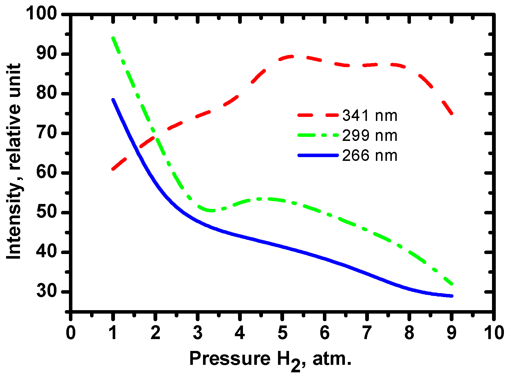
The efficiency of SRS conversion was measured versus the hydrogen pressure in the Raman cell, which was varied from 1 to 9 atm. Figure 3 shows the relative intensities of pumping radiation (266 nm), the first (299 nm) and the second (341 nm) Stokes components of SRS conversion as functions of hydrogen pressure at the SRS cell exit.
The intensities of 299 and 341 nm lines become equal at a hydrogen pressure of 2 atm, which allows ozone sounding under equal radiation energies at these wavelengths. However, to increase the upper sounding limit, a pressure of 1 atm is more efficient, since the energy is redistributed toward the 299 nm line, which is absorbed by ozone stronger than the 341 nm line.

3.2. IASI/MetOp

The IASI is mounted onboard the European Space Agency meteorological satellite MetOp. The satellite monitors CO2, CH4, N2O, CO, O3, and HNO3 atmospheric gases; measures the temperature and humidity profiles in the troposphere and lower stratosphere in the near real time within the European Program “European Polar System”. IASI provides for spectra of high radiometric quality with a resolution of 0.5 cm−1 in the range from 625 to 2760 cm−1 [20]. The ozone profiles were retrieved from satellite sounding data in the range 1025–1075 cm−1.
The satellite data were received by the 2.4 XLB satellite data reception station (Orbital Systems, USA) put into operation at IAO SB RAS in 2011 [21]. The information from the station allows comparison between the satellite data and SLS lidar sounding data.

4. Results

The VDO profiles retrieved from lidar sounding data are compared with the IASI/MetOp measured profiles.
VDO was measured at SLS IAO SB RAS during 2015. Using the above described technique, the retrieved profiles of ozone were calculated for the upper troposphere–lower stratosphere and compared with the IASI/MetOpt measured profiles. The range of lidar signal detection was from 6 to 15 km. The ozone vertical profile error was from 6 to 11%. The retrieval error is estimated by the sum
E s u m 2 = e 1 2 + e 2 2 + e 3 2
where e1 is the absorption cross-section error, e2 is the standard error of measurements in the photon counting mode, and e3 is the scattering ratio error. The absorption cross-section error e2 does not exceed 2% [18].
The standard error of measurements in the photon counting mode e2 is defined as
e 2 2 = 0.25 [ 1 N o n ( H ) + 1 N o f f ( H ) ]
The scattering ratio error e3 is defined as
e 3 2 = N o f f ( H ) [ N o f f ( H ) N n o i s e ( H ) ] 2 + N o f f ( H c a l i b ) [ N o f f ( H c a l i b ) N n o i s e ( H c a l i b ) ] 2 + K
where Hcalib—calibration height, N n o i s e —noise signal, K—constant value that appears due to the assumptions of the processing technique and the estimated value 3 ( 0.01 ) 2 .
The aerosol impact on the ozone profile in the troposphere and lower stratosphere is strong; therefore, the aerosol correction is to be used in the VDO retrieval algorithm.
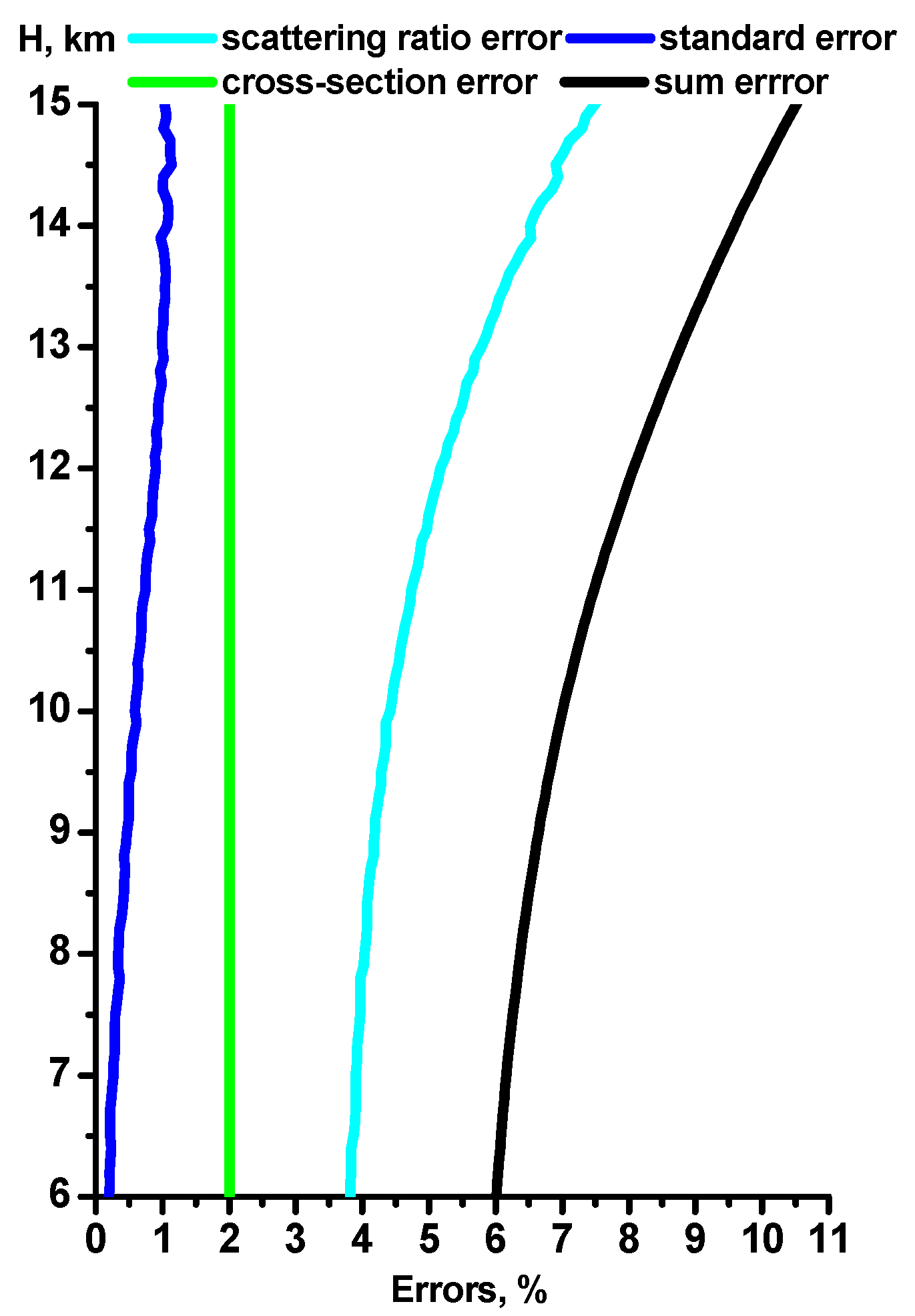
Before the VDO retrieval, the scattering ratio is calculated by the lidar signal at the wavelength 341 nm. This allows the aerosol correction with the use of a real scattering ratio instead of its model values, and thus minimizes the aerosol impact on the ozone profile in the dynamic gaseous and aerosol medium at tropospheric and lower stratospheric altitudes. Figure 4 shows the mean error of VDO retrieval over all the measurement days.
It should be noted that the lidar operates in the photon counting mode at a spatial resolution of 100 m, while the IASI profile has a step of 150 m and larger as the altitude increases, which is connected with the ozone profile retrieval algorithm of this interferometer [22]. IASI O3 retrieval errors, according to the estimates given in paper [23], reach values of 30%. The IASI curve is smoother and does not describe VDO in detail; the lidar measurements show the ozone behavior in more detail.
The coordinates and time of the lidar and satellite sounding are given in Table 4.
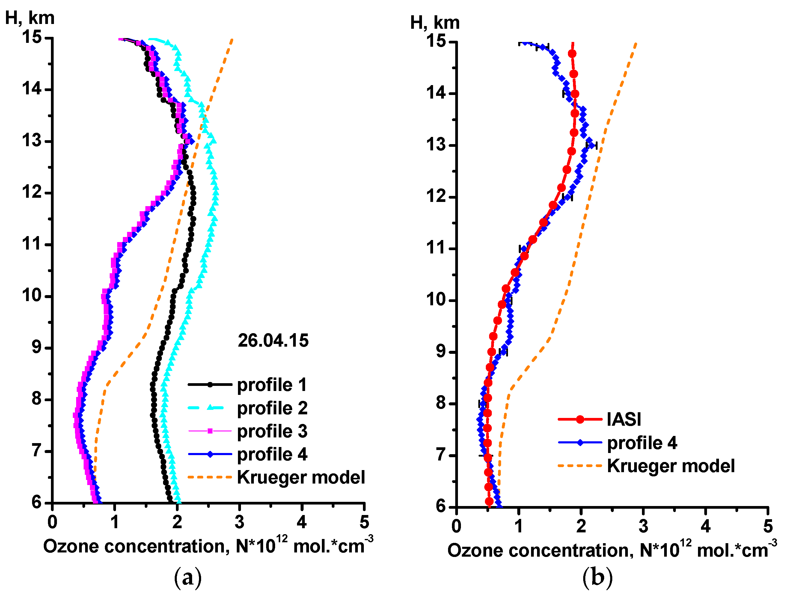
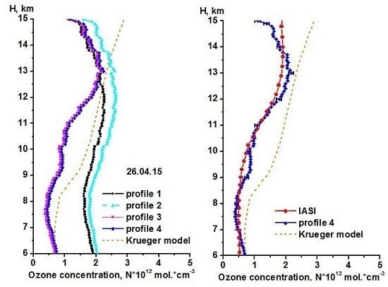
Figure 5 exemplifies the comparison of lidar and satellite vertical profiles of ozone measured on 26 April 2015; the VDO profiles are compared with the Krueger model [24].
We have analyzed the ozone profiles retrieved for April 2015 corrected to the temperature and aerosol and without corrections. One can see from Figure 5a that the efficiency of the corrections is significant. For the retrieval without temperature correction, the absorption cross-section constant σ299= 4.4 × 10⁻¹⁹ cm2 was used. High saturation of the aerosol component at tropospheric and lower stratospheric altitudes is corrected to both aerosol (terms C and D or Equations (12) and (15)) and temperature (term A or Equation (8)). Each correction used approaches the profiles to the IASI data.
Thus, the combination of corrections provides for a reliable ozone profile close to the IASI data (Figure 5b). The differences between profiles 3 and 4 are caused by the absorption cross-section values: the absorption cross-section in profile 4 is smaller than in profile 3; therefore, the values of profile 4 are higher than the values of profile 3 (Figure 5a).
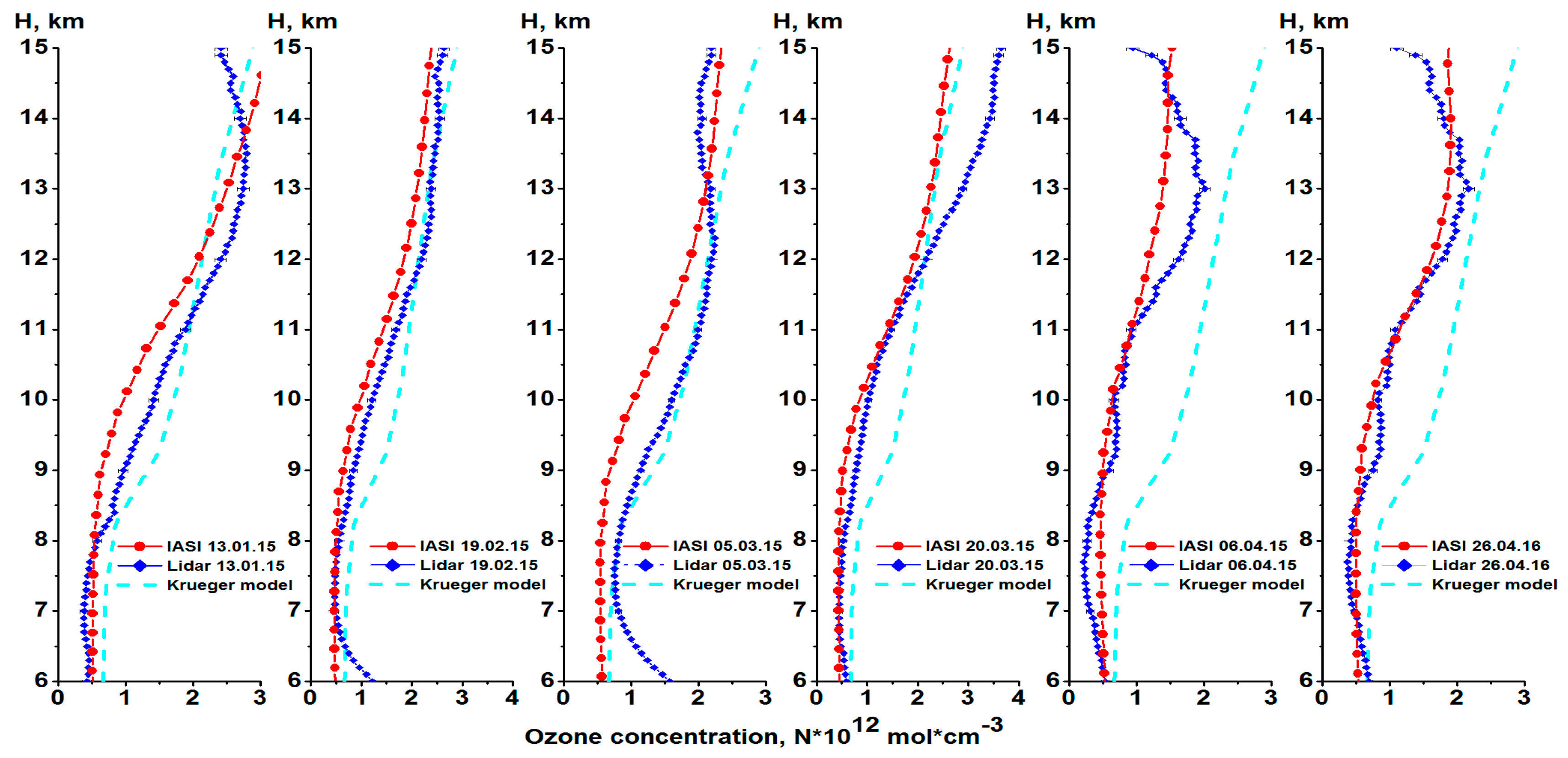
Figure 6 shows all the considered cases of comparison of ozone profiles measured at the SLS and retrieved from IASI data (see Table 4). The measurements are reduced to the total altitude range 6–15 km for convenience. Increased ozone concentrations measured at the SLS as compared to IASI are seen in the range from 8.5 to 12.5 km throughout the whole observation period.

5. Discussion

The following conclusions can be drawn from the analysis of the ozone profiles average over the period under study (Figure 7 and Figure 8).
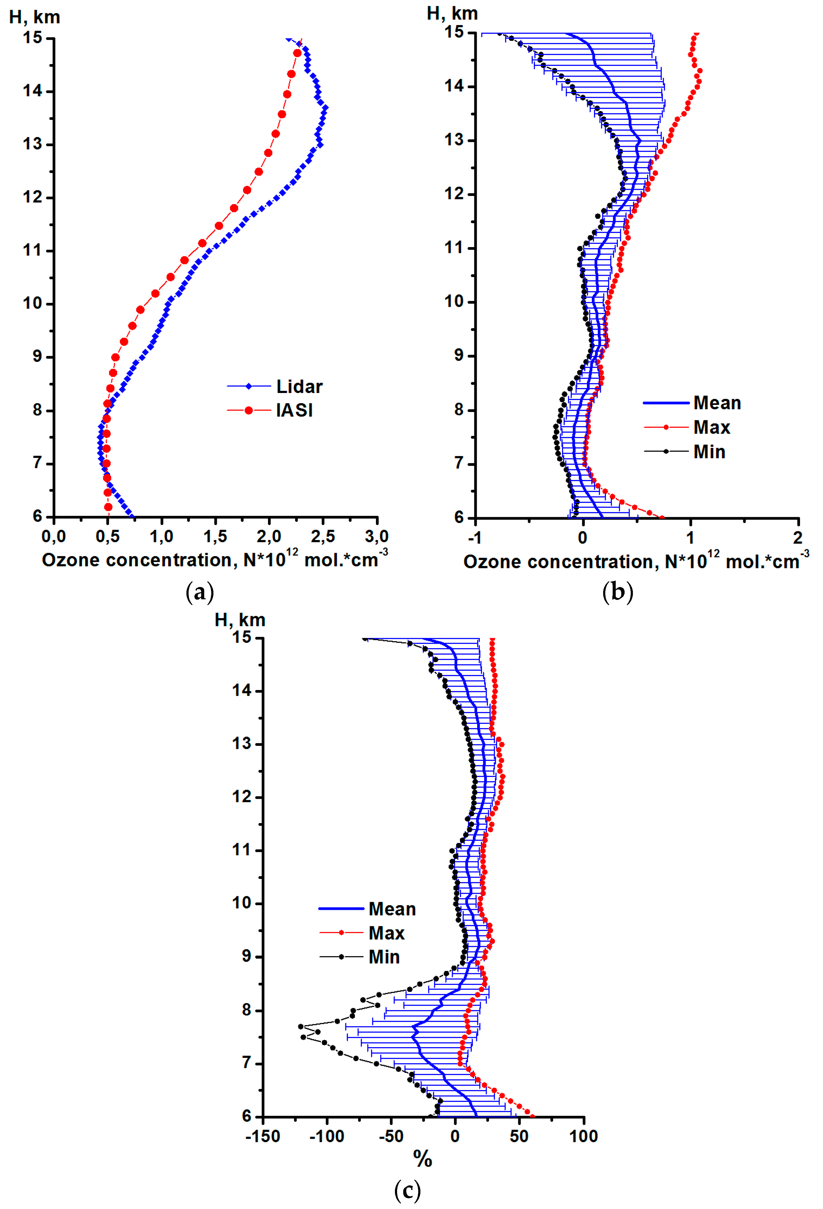
Figure 7a shows the mean lidar and satellite ozone profiles, and Figure 7b, the total difference between them (lidar–IASI) over all measurement days, as well as the standard deviation of this difference, minimum and maximum, and the mean. The error is calculated with the use of the standard deviation of the difference (lidar–IASI) and the ratio (lidar–IASI)/lidar over all days of measurements. Figure 7c shows the total difference between the lidar and IASI profiles normalized to the lidar profile for each measurement day, and the standard deviation with the minimum, maximum, and mean.
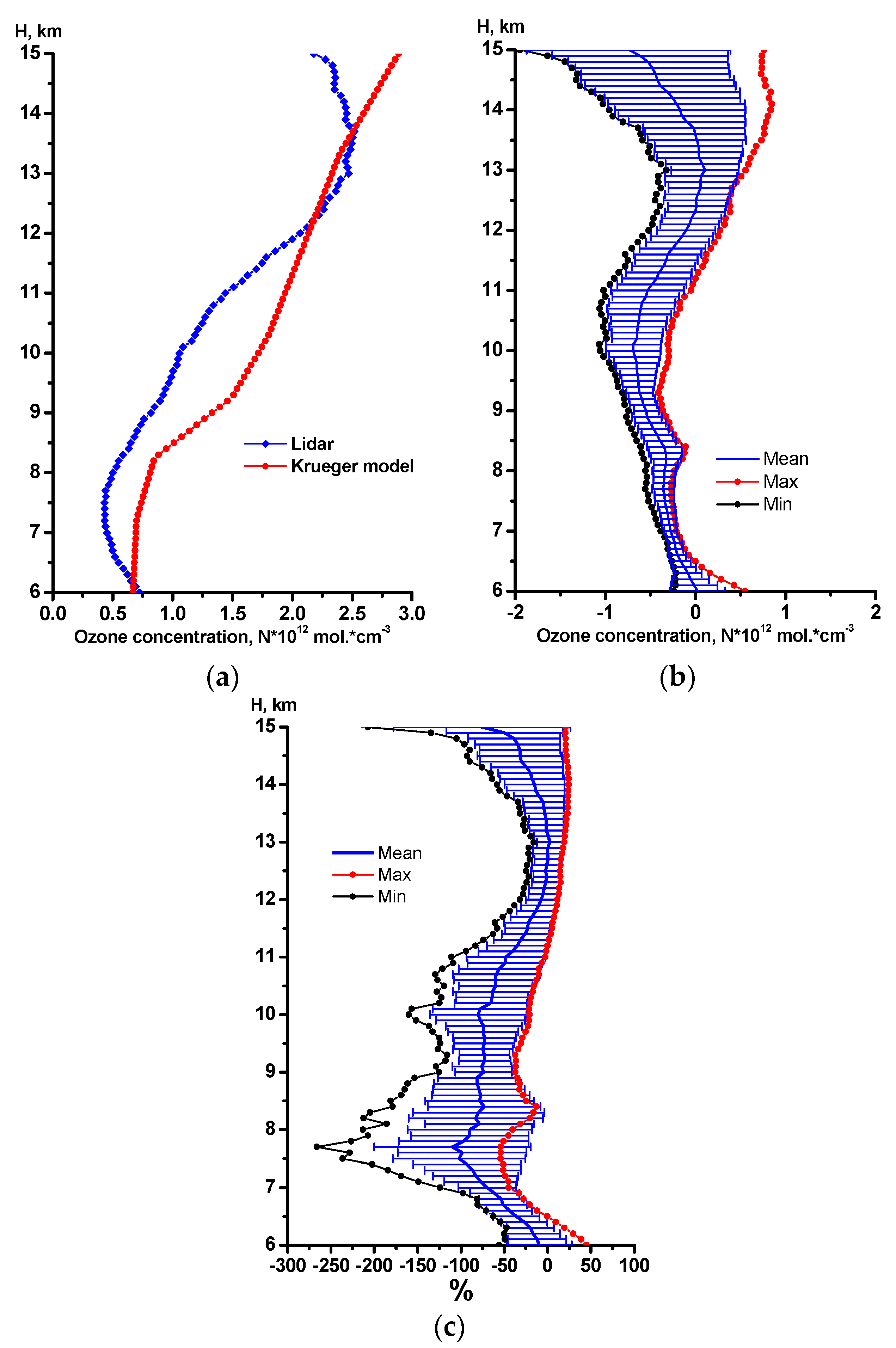
Figure 8a shows the mean lidar and Krueger model profiles, and Figure 8b, the total difference between them (lidar–Krueger model) over all measurement days, as well as the standard deviation of this difference, minimum and maximum, and the mean. Figure 8c shows the total difference between the lidar and Krueger model profiles normalized to the lidar profile for each measurement day, and the standard deviation with the minimum, maximum, and mean.
Thus, in Figure 7b, one can trace the variability of the difference between the lidar and satellite VDO in absolute units. The difference minima show how IASI data exceed the lidar data on VDO, and the minima, vice versa. The mean difference shows the difference between the lidar and IASI data over all measurement days. The normalized difference in Figure 7c shows more clearly the deviations between the values over all measurement days in percentage.
The difference between the lidar and IASI profiles of the ozone concentration grows with altitude. Hence, the mean difference in the ozone concentrations (lidar–IASI) varies from −1.56 × 10¹² mol. cm−3 at an altitude of 15 km to 0.53 × 10¹² mol. cm−3 at 13 km (Figure 6b). The maximal differences over all the profiles are from −0.01 × 10¹² mol. cm−3 at an altitude of 7.2 km to 1.08 × 10¹² mol. cm−3 at 14.3 km. The minimal differences over all the profiles vary from −0.77 × 10¹² mol. cm−3 at 15 km to 0.39 × 10¹² mol. cm−3 at 12.3 km.
Ozone shows pronounced annual variations; therefore, to find relative errors of its measurements with IASI, the difference in the concentrations was normalized to the lidar data: (Lidar–IASI)/Lidar. These data are shown in Figure 7c; it is seen that the mean relative difference is positive in the altitude ranges 6–6.5 and 8.4–14.6 km and attains 23.2% at an altitude of 12.4 km. The mean relative difference is negative in the altitude range from 6.5 to 8.4 km and 14.6–15 km: it attains the negative maximum of −33.8% at 7.5 km. The maximal relative difference changes from 3.45 to 60% in the range 6–15 km. The minimal relative difference over all the profiles in this range is −120.6% at 7.7 km; it attains 15.4% at 12.3 km. The relative difference varies in the range from −19.3 to 60% at 6 km and from −70.5 to 28.8% at 15 km.
Thus, the intercomparison performed shows that the absolute differences in the lidar and IASI measured ozone concentrations can change from −0.77 to 1.08 × 10¹² mol. cm−3; therefore, the relative difference is in the range from −120.6 to 60%.
It should be noted that the retrieved profiles of altitude distribution of the ozone concentration tend to IASI satellite data profiles more than to the Krueger model.

6. Conclusions

The results of using the developed techniques for VDO retrieval with temperature and aerosol correction in the altitude range 6–15 km during the DIAL lidar sounding of the atmosphere confirm the prospects of the wavelengths chosen (299 and 341 nm) for ozone lidar sounding.
Results of lidar measurements at 299 and 341 nm agree with model estimates, which point towards acceptable accuracy of ozone sounding in altitudes near 6–15 km.
At present, works are being carried out on optimization of optical and photoelectronic elements of the lidar signal detection system with the aim of increasing the upper limit of the sounding and improving the measurement accuracy. A more effective and comparatively easy-to-use ВаВ2O4 (BBO) crystal has been mounted as a fourth harmonic converter.

Acknowledgments

The work was supported by the Russian Science Foundation (Agreement No. 15-17-10001 in carrying out lidar measurements of ozone) and President of the Russian Federation within the Program for Support of Leading Scientific Schools (grant No. NSh-8199.2016.5). Authors Alexey V. Nevzorov and Oleg Romanovskii defined the research theme.

Author Contributions

The work presented here was conducted in collaboration with all a experiments. This manuscript was written by Oleg Romanovskii and Alexey A. Nevzorov. Sergey Dolgii and Olga Kharchenko checked the experimental results. All authors agreed to the submission of the manuscript.

Conflicts of Interest

The authors declare no conflict of interest.

References

  1. Sullivan, J.T.; McGee, T.J.; Sumnicht, G.K.; Twigg, L.W.; Hoff, R.M. A mobile differential absorption lidar to measure sub-hourly fluctuation of tropospheric ozone profiles in the Baltimore–Washington, D.C. Atmos. Meas. Tech. 2014, 7, 3529–3548. [Google Scholar] [CrossRef]
  2. Repasky, K.S.; Moen, D.; Spuler, S.; Nehrir, A.R.; Carlsten, J.L. Progress towards an autonomous field deployable diode-laser-based differential absorption lidar (DIAL) for profiling water vapor in the lower troposphere. Remote Sens. 2013, 6, 6241–6259. [Google Scholar] [CrossRef]
  3. Queißer, M.; Burton, M.; Fiorani, L. Differential absorption lidar for volcanic CO2 sensing tested in an unstable atmosphere. Opt. Exp. 2015, 23. [Google Scholar] [CrossRef] [PubMed]
  4. Galani, E.; Balis, D.; Zanis, P.; Zerefos, C.; Papayannis, A.; Wernli, H.; Gerasopoulo, E. Observations of stratosphere-to-troposphere transport events over the eastern Mediterranean using a ground-based lidar system. J. Geophys. Res. 2013, 108, 6634–6644. [Google Scholar] [CrossRef]
  5. Nakazato, M.; Nagai, T.; Sakai, T.; Hirose, Y. Tropospheric ozone differential-absorption lidar using stimulated Raman scattering in carbon dioxide. Appl. Opt. 2007, 46, 2269–2279. [Google Scholar] [CrossRef] [PubMed]
  6. Bukreev, V.S.; Vartapetov, S.K.; Veselovskii, I.A.; Galustov, A.S.; Kovalev, Y.M.; Prokhorov, A.M.; Svetogorov, E.S.; Khemelevtsov, S.S. Excimer-laser-based lidar system for stratospheric and tropospheric ozone measurements. Quantum Electron. 1994, 21, 591–596. [Google Scholar]
  7. Eisele, H.; Scheel, H.E.; Sladkovic, R.; Trickl, T. High resolution lidar measurements of stratosphere-troposphere exchange. J. Atmos. Sci. 1999, 56, 319–330. [Google Scholar] [CrossRef]
  8. Pommier, M.; Clerbaux, C.; Law, K.S.; Ancellet, G.; Bernath, P.; Coheur, P.F.; Hadji-Lazaro, J.; Hurtmans, D.; Nedelec, P.; Paris, J.D.; et al. Analysis of IASI tropospheric O3 data over Arctic during POLARCAT campaigns in 2008. Atmos. Chem. Phys. 2012, 12, 7371–7389. [Google Scholar] [CrossRef]
  9. Gazeaux, J.; Clerbaux, C.; George, M.; Hadji-Lazaro, J.; Kuttippurath, J.; Coheur, P.F.; Hurtmans, D.; Deshler, T.; Kovilakam, M.; Campbell, P.; et al. Intercomparison of polar ozone profiles by IASI/MetOp sounder with 2010 Concordiasiozonesonde observations. Atmos. Meas. Tech. 2013, 6, 613–620. [Google Scholar] [CrossRef]
  10. Viatte, C.; Schneider, M.; Redondas, A.; Hase, F.; Eremenko, M.; Chelin, P; Flaud, J.M.; Blumenstock, T.; Orphal, J. Comparison of ground-based FTIR and Brewer O3 total column with data from two different IASI algorithms and from OMI and GOME-2 satellite instruments. Atmos. Meas. Tech. 2011, 4, 535–546. [Google Scholar] [CrossRef]
  11. Molina, L.T.; Molina, M.T. Absolute absorption cross section of ozone in the 185 nm to 350 nm wavelengthrange. J. Geophys. Res. 1988, 91, 14501–14508. [Google Scholar] [CrossRef]
  12. El’nikov, A.V.; Zuev, V.V.; Marichev, V.N.; Tsaregorodtsev, S.I. First results of lidar observations of stratospheric ozone above western Siberia. Atmos. Ocean.Opt. 1989, 2, 841–842. [Google Scholar]
  13. McDermid, I.S.; Walsh, T.D.; Deslis, A.; White, M.L. Optical systems design for a stratospheric lidar system. Appl. Opt. 1995, 34, 6201–6210. [Google Scholar] [CrossRef] [PubMed]
  14. Godin, S.; David, C.; Lakoste, A.M. Systematic ozone and aerosol lidar measurements at OHP (44°N, 6°E) and Dumont. In Proceedings of the Abstracts of Papers: 17th International Laser Radar Conference, Sendai, Japan, 25–29 July 1994; pp. 409–412. [Google Scholar]
  15. Claude, H.; Scönenborn, F.; Streinbrecht, W.; Vandersee, W. DIAL ozone measurements at the Met. Obs. Hohenpeiβenberg: Climatology and trends. In Proceedings of the Abstracts of Papers: 17th International Laser Radar Conference, Sendai, Japan, 25–29 July 1994; pp. 413–415. [Google Scholar]
  16. Stefanutti, L.; Castagnoli, F.; Guasta, D.M.; Morandi, M.; Sacco, V.M.; Zuccagnoli, L.; Godin, S.; Megie, G.; Porteneuve, J. A four-wavelength depolarization backscattering LIDAR for IISC monitoring. Appl. Phys. B 1992, 55, 13–17. [Google Scholar] [CrossRef]
  17. Pazmino, A.F.; Lavorato, M.B.; Fochesatto, G.J. DIAL system for measurements of stratospheric ozone at Buenos Aires. In Advances in Laser Remote Sensing, Proceedings of the Selected Papers Presented at the 20th ILRC, Vichy, France, 10–14 July 2000; Ecole Polytechnique Impr: Paris, France, 2001. [Google Scholar]
  18. Malicet, J.; Daumont, D.; Charbonnier, J.; Parisse, C.; Chakir, A.; Brion, J. Ozone UV spectroscopy. II. Absorption cross-sections and temperature dependence. J. Atmos. Chem. 1995, 21, 263–273. [Google Scholar] [CrossRef]
  19. Zhu, H.; Qu, Z.W.; Grebenshchikov, S.Y.; Schinke, R.; Malicet, J.; Brion, J.; Daumont, D. Huggins band of ozone: Assignment of hot bands. J. Chem. Phys. 2005, 122. [Google Scholar] [CrossRef] [PubMed]
  20. Clerbaux, C.; Boynard, A.; Clarisse, L.; George, M.; Hadji-Lazaro, J.; Herbin, H.; Hurtmans, D.; Pommier, M.; Razavi, A.; Turquety, S.; et al. Monitoring of atmospheric composition using the thermal infrared IASI/MetOp sounder. Atmos. Chem. Phys. 2009, 9, 6041–6054. [Google Scholar] [CrossRef]
  21. Matvienko, G.G.; Belan, B.D.; Panchenko, M.V.; Romanovskii, O.A.; Sakerin, S.M.; Kabanov, D.M.; Turchinovich, S.A.; Turchinovich, Y.S.; Eremina, T.A.; Kozlov, V.S.; et al. Complex experiment on studying the microphysical, chemical, and optical properties of aerosol particles and estimating the contribution of atmospheric aerosol-to-earth radiation budget. Atmos. Meas. Tech. 2015, 8, 4507–4520. [Google Scholar] [CrossRef]
  22. August, T.; Klaes, D.; Schlüssel, P.; Hultberg, T.; Crapeau, M.; Arriaga, A.; O’Carroll, A.; Coppens, D.; Munro, R.; Calbet, X. IASI on Metop-A: Operational Level 2 retrievals after five years in orbit. J. Quant. Spectrosc. Radiat. Trans. 2012, 113, 1340–1371. [Google Scholar] [CrossRef]
  23. Keim, C.; Eremenko, M.; Orphal, J.; Dufour, G.; Flaud, J.M.; Höpfner, M.; Boynard, A.; Clerbaux, C.; Payan, S.; Coheur, P.F.; et al. Tropospheric ozone from IASI: Comparison of different inversion algorithms and validation with ozone sondes in the northern middle latitudes. Atmos. Chem. Phys. 2009, 9, 9329–9347. [Google Scholar] [CrossRef]
  24. Krueger, A.J.; Minzner, R.A. Mid-latitude ozone model for the 1976 U.S. Standard Atmosphere. J. Geophys. Res. 1976, 81, 4477–4488. [Google Scholar] [CrossRef]
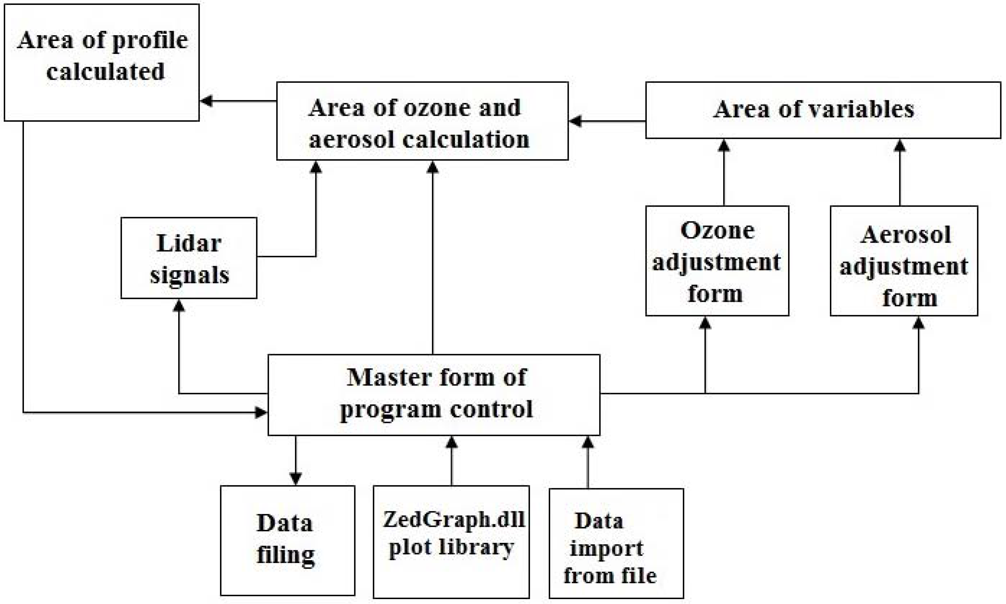
Figure 1. Structure of the software for vertical distribution of ozone (VDO) retrieval from laser sounding data.
Remotesensing 09 00447 g001
Figure 2. Block diagram of Siberian Lidar Station (SLS) ozone lidar: field diaphragm (1), cell for spectral selection with a PMT (2), mechanical shutter (3), rotating mirrors (RM); automated adjustment unit of an output rotating mirror (4); solid-state laser (Nd:YAG); SRS conversion cell with H2(H2) amplifiers/discriminators (AD)); high-voltage power supply units for the PMT(HSU); lenses (L1 and L2); system for synchronizing the shutter operation time and the instant of laser pulses emission (5).
Remotesensing 09 00447 g002
Figure 3. Relative intensities of pumping (266 nm), the first (299 nm) and the second (341 nm) Stokes conversion components of SRS conversion as functions of hydrogen pressure.
Remotesensing 09 00447 g003
Figure 4. Mean error of ozone profile retrieval over 2015.
Remotesensing 09 00447 g004
Figure 5. VDO profiles retrieved in comparison with the Kruger model: ozone profile without temperature and aerosol corrections (1), ozone profile with temperature and without aerosol corrections (2), ozone profile without temperature and with aerosol corrections (3), combination of corrections (aerosol and temperature) (4) (a); VDO profiles retrieved in comparison with the Kruger model and IASI satellite data (b).
Remotesensing 09 00447 g005
Figure 6. Intercomparison of vertical profiles of ozone for 2015.
Remotesensing 09 00447 g006
Figure 7. Mean vertical profiles of ozone (a), their difference (Lidar–IASI) in abs. units (b), and the relative difference (Lidar–IASI)/lidar (c).
Remotesensing 09 00447 g007
Figure 8. Mean vertical profiles of ozone (a), their difference (Lidar–Krueger) in abs. units (b), and the relative difference (Lidar–Krueger)/lidar (c).
Remotesensing 09 00447 g008
Table 1. Specifications of lidars used for measurements of stratospheric ozone.
Country, Observations SiteStart of Measu-RementsRadiation Source: Wavelength, nm/Pulse Energy, mJ/Pulse Repetition Frequency, HzReceiving Mirror (Diameter), mRef.
Russia, Tomsk (56.5°N, 85°E)1989XeCl + SRS (H2)
308/100/100;
353/50/1000
2.2
0.5
0.3
[12]
USA, California (34°N, 118°E)1986XeCl + SRS (H2)
308–353
0.9[13]
France, Provanсe (44°N, 6°E)1986XeCl+ Nd:YAG
308/250/50;
355/150/50
4 mirrors of 0.53[14]
Germany, Hohenpeiβenberg (48°N, 11°E)1987XeCl + SRS (H2)
308/300/20;
353/150/20
0.9[15]
France, Italia, the Antarctic (66°S, 140°E)1991XeCl+ Nd:YAG
308/180/80;
355/150/10
0.8[16]
Argentina, Buenos-Aires (35°S, 59°W)1999XeCl+ Nd:YAG
308/300/100;
355/255/10
0.5[17]
Table 2. Sets of wavelengths that correspond to Stokes (C) frequencies of SRS conversion in H2, D2, and CO2.
Pumping RadiationWavelength, nm
H2
C1 C2
D2
C1 C2 C3
CO2
C1 C2
Nd:YAG, 266 nm299 341289 316287 299
KrF, 248 nm277 313268 291 319
Table 3. Ozone absorption cross-section (cm2) at the ozone sounding wavelengths [18,19].
Wavelength, nmTemperature, K
218228243273295
On line
2994.1 × 10−194.1 × 10−194.25 × 10−194.3 × 10−194.6 × 10⁻¹⁹
Off line
3416 × 10−226 × 10−226 × 10−226 × 10−221.2 × 10⁻²¹
Table 4. Coordinates and time of satellite and lidar sounding used for comparison of VDO profiles for 2015.
DateSiberian Lidar StationMetOp (IASI) Satellite
Greenwich TimeCoordinates
(56.5°N, 85.0°E)
Greenwich TimeCoordinates
13 January 201511:53–13:4514:1756.472°N, 85.387°E
19 February 201512:39–14:1314:5356.681°N, 85.164°E
5 March 201513:05–14:5615:0256.472°N, 85.118°E
20 March 201513:32–15:2414:5356.691°N, 85.124°E
6 April 201514:25–16:1715:4156.254°N, 84.935°E
26 April 201515:11–17:0315:2656.585°N, 84.594°E