A CMOS-Thyristor Based Temperature Sensor with +0.37 °C/−0.32 °C Inaccuracy


University of Electronic Science and Technology of China, Chengdu 610054, China
*
Author to whom correspondence should be addressed.
Micromachines 2020, 11(2), 124; https://doi.org/10.3390/mi11020124
Submission received: 12 December 2019
/
Revised: 14 January 2020
/
Accepted: 21 January 2020
/
Published: 22 January 2020
(This article belongs to the Special Issue Temperature Sensors—Fundamentals, Detectors, Arrays and Applications)
Abstract
:This paper describes a voltage controlled oscillator (VCO) based temperature sensor. The VCOs are composed of complementary metal–oxide–semiconductor (CMOS) thyristor with the advantage of low power consumption. The period of the VCO is temperature dependent and is function of the transistors’ threshold voltage and bias current. To obtain linear temperature characteristics, this paper constructed the period ratio between two different-type VCOs. The period ratio is independent of the temperature characteristics from current source, which makes the bias current generator simplified. The temperature sensor was designed in 130 nm CMOS process and it occupies an active area of 0.06 mm2. Based on the post-layout simulation results, after a first-order fit, the sensor achieves an inaccuracy of +0.37/−0.32 °C from 0 °C to 80 °C, while the average power consumption of the sensor at room temperature is 156 nW.
1. Introduction
Temperature sensors are desirable for temperature sensing and compensation in modern applications, such as medical, environmental monitoring, thermal monitoring and wireless Internet-of-Things (IoT) platforms [1,2,3]. Most of such applications are battery powered for portability, durability or deployment flexibility [4,5], and put a strict power budget on temperature sensor which drives the power consumption to sub-μW and even to near-zero.
Prior works have demonstrated low-power-consumption temperature sensors based on bipolar junction transistors (BJT) [6,7,8], resistors [9,10], and complementary metal–oxide–semiconductor (CMOS) [11,12,13,14,15,16]. BJT-based temperature sensors converse the temperature by comparing a temperature-dependent voltage to a temperature-insensitive voltage or inversely temperature-dependent voltage. The voltage difference between these two voltages is quantized by a ΣΔ-ADC (Analog-to-Digital Converter), which achieves high resolution up to 0.002 °C and inaccuracy less than ±0.2 °C [6,7,8]. Resistor-based temperature sensors can achieve higher resolution and energy efficiency than BJT-based sensors. As discussed in Ref. [9], the authors use a temperature-dependent RC (Resistor and Capacitor) filter to extract the temperature information. In Ref. [10], the authors build a resistor based Wheatstone bridge whose voltage difference is proportional to the temperature. Both the temperature-dependent phase shift and voltage difference are sequentially digitized by ΣΔ-ADCs. ΣΔ-ADCs achieve high resolution at the cost of high power consumption and hardware cost from the decimation filter which normally are not mentioned in papers. Thus, the sacrifice of power consumption and hardware make BJT and resistor based temperature sensors not an optimal choice for battery powered applications. CMOS based temperature sensors are normally composed of digital delay cells. They are much more area efficient and easier to scale down with process. The authors in Ref. [13] demonstrate a VCO based temperature sensor. The temperature information is extracted by two VCOs with different temperature-dependent frequency. The temperature sensor is fully composed of digital circuit and thus achieves an attractive area. On the other hand, the authors in Ref. [12] firstly create a temperature-dependent current and then transfer the current to frequency by VCOs. It provides better linearity and accuracy.
This paper proposes a VCO based temperature sensor and the VCO is composed of two-stage CMOS thyristor to simplify the circuit and achieve low power consumption.
2. Proposed CMOS Thyristor Based VCO
The proposed VCO is composed of multi-stage delay cells circled together. The desired oscillation frequency is inversely proportional to the number of stages and delay time of delay cell. Increasing the stages or delay time is necessary to reduce the oscillation frequency for low power consumption. Commonly, CMOS invertor is adopted as delay cell for its simplicity and scalability [12,13,14,15,16]. Its delay time is process dependent and ranges from ps to ns in sub-µm CMOS process. It may achieve µs delay by using the current-starved architecture but at the cost of large capacitors [14,15,16].
2.1. Basics of CMOS Thyristor Based Delay Cell
CMOS thyristor was proposed to increase the delay [17,18]. As shown in Figure 1, M2 and M4 work as a thyristor. M3 and M5 receive the input signal VIP and VIN, respectively, while VIN is the complementary signal of VIP. Current source IBN is used to sink current from VON via switch M1 according to the status of VIP. C0 is the total capacitance on node VON. When VIP is low, M5/M3 are conducted and M1 is non-conducted, VON and VOP are reset to VDD and GND, respectively. When VIP is changing to high, M5/M3 switch off and M1 switches on. Current source IBN starts sinking current from VON which results in node voltage decreasing from VDD. Approximately, M4 conducts when VIP reaches VDD-Vthp, where Vthp is the threshold voltage of M4. After that, VOP is charged from power supply VDD via M4 and increased rapidly. Sequentially, M2 conducts when VOP reaches Vthn and discharges current from VON together with IBN, where Vthn is the threshold voltage of M2. It accelerates the node voltage decrease on VON and constitutes a positive feedback loop between M2 and M4. Once the positive feedback is built, VON and VOP toggle to the opposite state in a short time. The corresponding delay value is calculated as [17]
where the first term on the right is the delay contributed by discharging C0, the second term is the delay contributed by charging C1, and δt is the regeneration time of the CMOS thyristor. C1 is the parasitic capacitance of VOP. In reality, because of the subthreshold effect, M4 charges the C1 simultaneously with M2 discharging C0. The second term can be neglected. Comparing to the first term, the regeneration time δt is small and can be omitted. The delay value can be approximated as
Both adopting a larger capacitor C0 and reducing sink current IBN are effective to increase the delay value. Since C0 generally adopts metal capacitor which is mostly temperature independent, the temperature coefficients are decided by the ratio of Vthp/IBN.
2.2. Proposed CMOS Thyristor Based VCO
VCO is generally constituted by multiple stages (beyond three stages) to satisfy the desired frequency. The more stages it has, the more devices are required, which would consume more power and also deteriorate the wave performance. To simplify the circuit and reduce device counts, a two-stage ring VCO is proposed and shown in Figure 2. The delay cell is composed of the CMOS thyristor based delay cell aforementioned. In the proposed architecture, the negative output VON1 of the first stage is connected to the negative input VIN of the second stage and VOP1 is connected to VIP. In this way, four-stage inversion is produced in the closed loop and thus makes it easy to satisfy the oscillation requirement of 360° phase shift.
Referred to the delay value of CMOS thyristor based delay cell in Equation (1), the oscillation period of the proposed VCO is given by
3. Temperature Sensor Architecture
As shown in Figure 3, two types of VCO are adopted to constitute the proposed temperature sensor. At the top, P-type VCO is composed of Delay_Cell_Ps. The delay value of Delay_Cell_P is approximately the discharging time on VON via IREFN according to aforementioned analysis. Referring to Equation (3), the period of P-type VCO is given as
Similarly, N-type VCO is composed of Delay_Cell_Ns. The delay value of Delay_Cell_N is approximately the charging time on VOP via IREFP according to aforementioned analysis. Referring to Equation (3), the period of N-type VCO is given as
Based on Equations (4) and (5), the ratio between TVCO_P and TVCO_N is calculated
C0 and C3 are composed of metal capacitors, which are temperature independent. IREFP and IREFN come from the same current source and they will have the same temperature characteristics and value. Thus, the ratio can be updated as
Because Vthp is temperature dependent to the first order [19], ratio_T is proportional to the temperature [13]. Thus, the ratio of the two-type VCO is used to detect temperature.
The complete block diagram of the proposed temperature sensor is shown in Figure 4. The left block is temperature sensor core which is composed of a P-type and a N-type VCO aforementioned. Bias current generator is used to provide the charging/discharging current IREFN/IREFP.
The right block calculates the ratio between periods and transfers temperature to digital codes via two counters. The working principle of the Temperature to Digital is as follows. After RST switches to low, both counters start counting simultaneously. Counter1 counts CLKP to a constant value M and generates a flag signal STOP. When receiving STOP signal, Counter2 ends counting CLKN with a value of P. The counting time of both counters are equal and it can be expressed as
The ratio between periods can be obtained
Since M is a constant value, P represents the ratio_T and thus is proportional to the temperature. Eventually, P is converted to digital code of Tcode and output for measurement.
4. Circuit Implementation
4.1. Delay Cell
The detail of delay cell is shown in Figure 5. The bias current IREFP and IREFN are composed of NMOS and PMOS working in saturation region separately. The switches M1 in both delay cells adopt thin-gate MOSFET to achieve fast switching and low conductive resistance. Considering the charging/discharging current of IREFP/IREFN on the magnitude of nA, all the others are thick-gate MOSFET to reduce influence of leakage current. Instead of just using C0 and C3 as what is shown in Figure 3, C1 and C2 are added to keep the load balance between Delay_Cell_P and Delay_Cell_N. MIM (Metal-Insulator-Meatal) capacitors are adopted for C0-C3 to maintain process and temperature independence.
4.2. Bias Current Generator
Bias current could be designed with any kind of temperature characteristics, such as proportional, exponential, or independent [12,20]. It is hard to obtain a temperature dependent or independent current with outstanding linearity even at the cost of power or hardware. Instead of designing a high-linearity and temperature-dependent current generator, this paper adopted a simple current generator since the proposed temperature sensor is independent of IBN. Figure 6 shows the architecture of the bias current generator.
As described in Equation (6), IREFP and IREFN can be removed as long as they have the same temperature characteristics and magnitude. Thus, the bias current generator is simply composed of M1-M4. M1 and M3 work in sub-threshold region and provide the source current Iref.
where μ is mobility, Cox is oxide capacitance, W is transistor width, L is transistor length, m is subthreshold slop factor, VT is thermal voltage (kT/q), Vth is transistor threshold voltage and VDD is the power supply voltage. The source current is mirrored to Delay_Cell_P and Delay_Cell_N for IREFN and IREFP respectively. According to Equation (6) and Equation (7), IREFP and IREFN should be of equal magnitude. Current mismatch between IREFP and IREFN will deteriorate the temperature linearity. To maintain the same magnitude of IREFP and IREFN, the optimal matching among current mirrors (M1/M2/M6 and M4/M5) is required. Thus, the maximum length of 20 µm is adopted for the current-mirror MOSFETs. The current generator is of simple structure but suffers from the influence of the power supply. Thus, a stable and clean power supply is required.
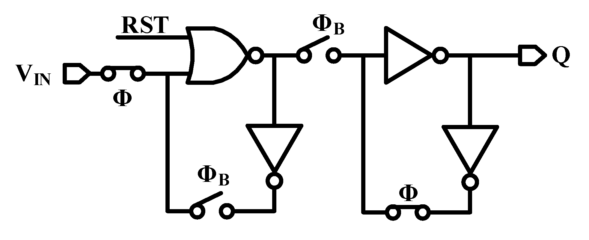
4.3. Quasi-Static D-Flip Flop
The counters consist of two cascaded dividers (divide by two) which are composed of quasi-static D-Flip Flop for low power consumption (shown in Figure 7). Note that no risk presents in the glitches. The D-Flip Flop adopts dual-feedback loop to remove the impact from leakage. When the counting value of Counter1 reaches M, the input clock is blocked, and all dividers in Counter1 and Counter2 stop working and hold the states. Counting value P in Counter2 is output as Tcode for measurement.
5. Simulation Results
The proposed temperature sensor was designed in 130 nm CMOS process. It does not need external voltage, current and frequency reference. The layout is shown in Figure 8 and the active area is 0.065 mm2. The power supply voltage is 1 V to achieve low power consumption while keeping the bias current generator working properly under all corners and temperatures. The bias current was set to 6 nA with oscillation periods about 240 μs under typical corner and room temperature. The average power is 156 nW at 27 °C while VCO consumes 89%, as shown in Figure 9.
5.1. VCO Simulation
The proposed VCOs were designed and simulated. Figure 10 shows the simulated results. Since the bias generator works in sub-threshold region, the bias current has exponential relation to temperature. Accordingly, both VCO periods have exponential relation to temperature as shown in Figure 10a. Because of the threshold voltage difference between PMOS and NMOS, TVCO_P is larger than TVCO_N. ratio_T is shown in Figure 10b. It is inversely proportional to the temperature with an outstanding linearity which is in good accordance with the analysis in Equation (7).
5.2. Temperature Sensor Simulation
As shown in Figure 10b, ratio_T changes slightly over the temperature range of 0 °C to 80 °C. To maintain a 10-bit level resolution, Counter1 is designed to be 14 bits. According to the Monte Carlo simulations, ratio_T is always greater than 1 but less than 2, so Counter2 is set to be 15 bits. The proposed temperature sensor is simulated from 0 °C to 80 °C. Both MOSFET mismatches and MIM capacitor mismatch are taken into account and verified with 20 Monte Carlo runs. The standard deviation of the transistors’ mismatch and MIM capacitors’ mismatch are 0.3% and 0.03%, respectively, which are provided by the foundry. Figure 11a shows a temperature error of +1.65 °C /−1.84 °C after 1st order polyfit. Figure 11b shows a temperature error of +0.57 °C /−0.44 °C after 2nd order polyfit.
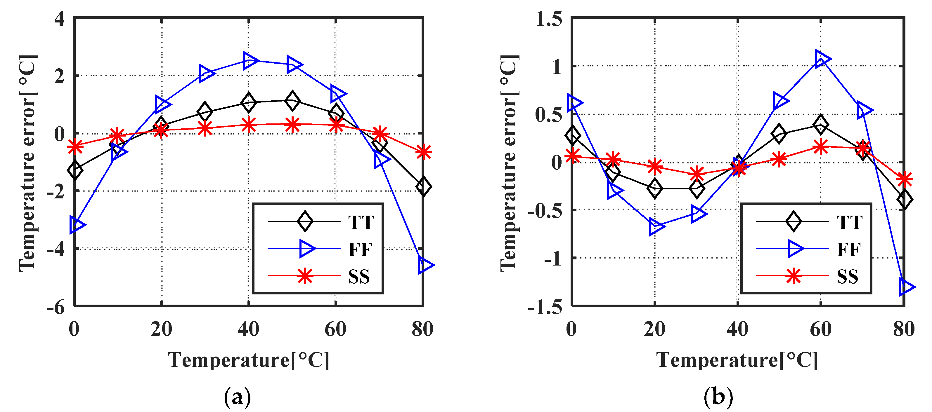
The proposed temperature sensor exhibits a systematic error profile dominated by the nonlinearity of ratio_T across the temperature range which is in good accordance with the analysis in Equation (7). After 1st order polyfit and the nonlinearity removal (Figure 12a), a maximum temperature error of +0.37 °C/−0.32 °C was observed across a 0 °C to 80 °C temperature range. After 2nd order polyfit and the nonlinearity removal (Figure 12b), a maximum temperature error of +0.17 °C/−0.19 °C was observed.
The proposed temperature sensor was verified under corners. The results are shown in Figure 13. The SS corner shows the best performance while the worst performance can be observed in the FF (Fast-Fast) corner. This is because in the FF corner, the MOSFETs have the lowest threshold voltage. When we increase the reference current, the oscillation period reduces. That results in a worse approximation in Equation (2) and poor linearity.
Table 1 compares the proposed sensor with the state-of-the-art temperature sensors. The proposed sensor does not need any external clock references or voltage regulators. It is designed with simple current mirrors and CMOS thyristors, and it achieves a competitive inaccuracy of +0.37/−0.32 °C and low power consumption of 156 nW within a compact area of 0.06 mm2.
6. Conclusions
A CMOS thyristor based temperature sensor was proposed in this paper. Two VCOs composed of CMOS thyristor with different threshold voltage were exploited. The period ratio between two VCOs extracts the temperature information. The ratio calculation is simply realized by two counters where a constant-value counter stops another free running counter. Therefore, the external clock reference was avoided. A diode-connected bias current generator was exploited for its simplicity and little impact on the temperature extraction. The prototype was designed in 130 nm CMOS process and occupies an active area of 0.06 mm2. According to the post-layout simulation, it achieves an inaccuracy of +0.37/−0.32 °C from 0 °C to 80 °C after 1st order polyfit and nonlinearity removal with a power consumption of 156 nW.
Author Contributions
Conceptualization, J.L.; Formal analysis, J.L.; Methodology, J.L.; Project administration, K.W.; Supervision, Q.Y.; Validation, J.L., Y.L. and S.Y.; Writing—original draft, J.L.; Writing—review & editing, N.N., Y.L. All authors have read and agreed to the published version of the manuscript.
Funding
This research was funded by Science and Technology on Analog Integrated Circuit Laboratory under project NO. JCKY2019210C057.
Conflicts of Interest
The authors declare no conflict of interest.
References
- Floyd, M.; Allen-Ware, M.; Rajamani, K.; Brock, B.; Lefurgy, C.; Drake, A.J.; Pesantez, L.; Gloekler, T.; Tierno, J.A.; Bose, P.; et al. Introducing the adaptive energy management features of the Power7 chip. IEEE Micro 2011, 31, 60–75. [Google Scholar] [CrossRef]
- Oshita, T.; Shor, J.; Duarte, D.E.; Kornfeld, A.; Zilberman, D. Compact BJT-based thermal sensor for processor applications in a 14 nm tri-gate CMOS process. IEEE J. Solid State Circuits 2015, 50, 799–807. [Google Scholar] [CrossRef]
- Shim, D.; Jeong, H.; Lee, H.; Rhee, C.; Jeong, D.K.; Kim, S. A process-variation-tolerant on-chip CMOS thermometer for auto temperature compensated self-refresh of low-power mobile DRAM. IEEE J. Solid State Circuits 2013, 48, 2550–2557. [Google Scholar] [CrossRef]
- Ha, S.; Akinin, A.; Park, J.; Kim, C.; Wang, H.; Maier, C.; Cauwenberghs, G.; Mercier, P.P. A 16-channel wireless neural interfacing SoC with RF-powered energy-replenishing adiabatic stimulation. In Proceedings of the 2015 Symposium on VLSI Circuits (VLSI Circuits), Kyoto, Japan, 17–19 June 2015; pp. C106–C107. [Google Scholar]
- Wang, H.; Mercier, P.P. A 51 pW reference-free capacitive discharging oscillator architecture operating at 2.8 Hz. In Proceedings of the 2015 IEEE Custom Integrated Circuits Conference (CICC), San Jose, CA, USA, 28–30 September 2015; pp. 1–4. [Google Scholar]
- Pertijs, M.A.P.; Makinwa, K.A.A.; Huijsing, J.H. ACMOS smart temperature sensor with a inaccuracy of C from to 125 C. IEEE J. Solid State Circuits 2005, 40, 2805–2815. [Google Scholar] [CrossRef]
- Aita, A.L.; Pertijs, M.A.P.; Makinwa, K.A.A.; Huijsing, J.H. A CMOS smart temperature sensor with a batch-calibrated inaccuracy of C from C to 130 C. In Proceedings of the 2009 IEEE International Solid-State Circuits Conference-Digest of Technical Papers, San Francisco, CA, USA, 8–12 February 2009; pp. 342–343. [Google Scholar]
- Sebastiano, F.; Breems, L.J.; Makinwa, K.A.A.; Drago, S.; Leenaerts, D.M.W.; Nauta, B. A 1.2-V 10-μW NPN-based temperature sensor in 65-nm CMOS with an inaccuracy of 0.2 °C from 70° C to 125 °C. IEEE J. Solid State Circuits 2010, 45, 2591–2601. [Google Scholar] [CrossRef] [Green Version]
- Pan, S.; Gürleyük, Ç.; Pimenta, M.F.; Makinwa, K.A.A. A 0.12 mm2 Wien-Bridge Temperature Sensor with 0.1 °C (3σ) Inaccuracy from −40 °C to 180 °C. In Proceedings of the 2019 IEEE International Solid-State Circuits Conference-Digest of Technical Papers, San Francisco, CA, USA, 17–21 February 2019; pp. 184–186. [Google Scholar]
- Pan, S.; Makinwa, K.A.A. A Wheatstone Bridge Temperature Sensor with a Resolution FoM of 20fJ.K2. In Proceedings of the 2019 IEEE International Solid-State Circuits Conference-Digest of Technical Papers, San Francisco, CA, USA, 17–21 February 2019; pp. 186–188. [Google Scholar]
- Yang, K.; Dong, Q.; Jung, W.; Zhang, Y.; Choi, M.; Blaauw, D.; Sylvester, D. A 0.6 nJ −0.22/+0.19 °C Inaccuracy Temperature Sensor Using Exponential Subthreshold Oscillation Dependence. In Proceedings of the 2017 IEEE International Solid-State Circuits Conference-Digest of Technical Papers, San Francisco, CA, USA, 5–9 February 2017; pp. 160–162. [Google Scholar]
- Jeong, S.; Foo, Z.; Lee, Y.; Sim, J.Y.; Blaauw, D.; Sylvester, D. A fully-integrated 71 nW CMOS temperature sensor for low power wireless sensor nodes. IEEE J. Solid State Circuits 2014, 49, 1682–1693. [Google Scholar] [CrossRef]
- Anand, T.; Makinwa, K.A.A.; Hanumolu, P.K. A VCO Based Highly Digital Temperature Sensor with 0.034 °C/mV Supply Sensitivity. IEEE J. Solid-State Circuits 2016, 51, 2651–2663. [Google Scholar] [CrossRef]
- Lin, Y.S.; Sylvester, D.; Blaauw, D. An Ultra Low Power 1 V, 220 nW Temperature Sensor for Passive Wireless Applications. In Proceedings of the 2008 IEEE Custom Integrated Circuits Conference(CICC), San Jose, CA, USA, 21–24 September 2008; pp. 507–510. [Google Scholar]
- Kim, C.K.; Kong, B.S.; Lee, C.G.; Jun, Y.H. CMOS Temperature Sensor with Ring Oscillator for Mobile DRAM Self-refresh Control. In Proceedings of the 2008 IEEE International Symposium on Circuits and Systems, Seattle, WA, USA, 18–21 May 2008; pp. 3094–3097. [Google Scholar]
- Hwang, S.; Koo, J.; Kim, K.; Lee, H.; Kim, C. A 0.008 mm2 500 μW 469 kS/s Frequency-to-Digital Converter Based CMOS Temperature Sensor with Process Variation Compensation. IEEE Trans. Circuits Syst. I Reg. Pap. 2013, 60, 2241–2248. [Google Scholar] [CrossRef]
- Kim, G.; Kim, M.K.; Chang, B.S.; Kim, W. A low-voltage, low-power CMOS delay element. IEEE J. Solid State Circuits 1996, 31, 966–971. [Google Scholar]
- Saft, B.; Schäfer, E.; Jäger, A.; Rolapp, A.; Hennig, E. An Improved Low-Power CMOS Thyristor-Based Micro-to-Millisecond Delay Element. In Proceedings of the ESSCIRC 2014—40th European Solid State Circuits Conference (ESSCIRC), Venice Lido, Italy, 22–26 September 2014; pp. 123–126. [Google Scholar]
- Tsividis, Y.P. Operation and Modeling of the MOS Transistor; McGraw-Hill: New York, NY, USA, 1987. [Google Scholar]
- Wang, H.; Mercier, P.P. A 3.4-pW 0.4-V 469.3 ppm/°C Five-Transistor Current Reference Generator. IEEE Solid State Circuits Lett. 2018, 1, 122–125. [Google Scholar] [CrossRef]
- Xin, H.; Andraud, M.; Baltus, P.; Cantatore, E.; Harpe, P. A 174 pW–488.3 nW 1 S/s–100 kS/s all-dynamic resistive temperature sensor with speed/resolution/resistance adaptability. IEEE Solid State Circuits Lett. 2018, 1, 70–73. [Google Scholar] [CrossRef]
Figure 1.
Complementary metal–oxide–semiconductor (CMOS) thyrsitor based delay cell.

Figure 2.
Proposed CMOS thyristor based voltage controlled oscillator (VCO).

Figure 3.
Proposed temperature sensor architecture.
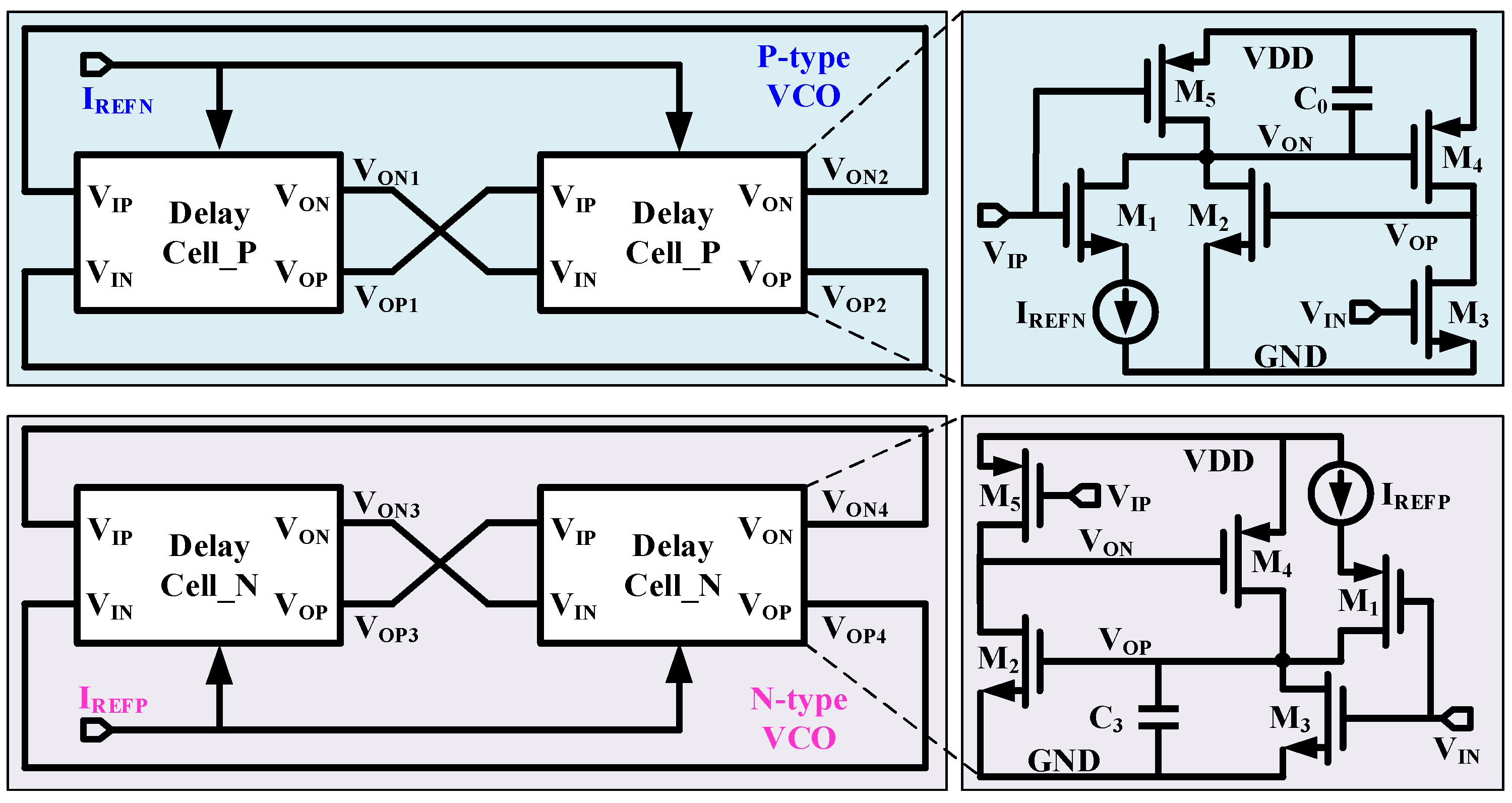
Figure 4.
Block diagram of the temperature sensor.

Figure 5.
Detail of delay cell (a) Delay_Cell_P (b) Delay_Cell_N.

Figure 6.
Bias current generator.
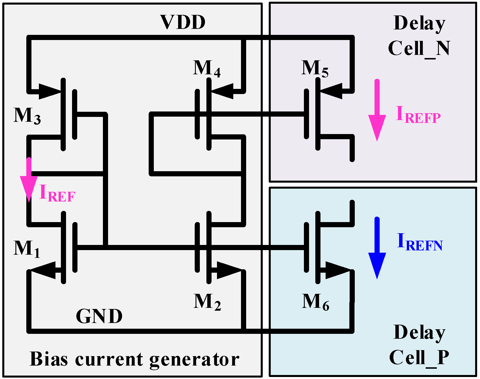
Figure 7.
Quasi-static D-Flip Flop.

Figure 8.
Layout.

Figure 9.
Power breakdown.

Figure 10.
Simulated temperature performance of VCO (a) periods vs. temperature (b) ratio_T vs. temperature.
Figure 10.
Simulated temperature performance of VCO (a) periods vs. temperature (b) ratio_T vs. temperature.

Figure 11.
Simulated temperature error (a) after 1st order polyfit, (b) after 2nd order polyfit.

Figure 12.
Simulated temperature error (a) after 1st order polyfit and systematic nonlinearity removal (b) after 2nd order polyfit and systematic nonlinearity removal.
Figure 12.
Simulated temperature error (a) after 1st order polyfit and systematic nonlinearity removal (b) after 2nd order polyfit and systematic nonlinearity removal.

Figure 13.
Simulated temperature error vs corners (a) after 1st order polyfit; (b) after 2nd order polyfit.
Figure 13.
Simulated temperature error vs corners (a) after 1st order polyfit; (b) after 2nd order polyfit.


Table 1.
Summarizes the performance of the proposed sensor.
| [13] | [12] | [11] | [21] | This Work * | |
|---|---|---|---|---|---|
| Technology [nm] | 65 | 180 | 180 | 65 | 130 |
| Area [mm2] | 0.004 | 0.09 | 0.22 | 0.06 | 0.06 |
| Supply Voltage [V] | 0.85–1.05 | 1.2 | 1.2 | 1 | 1 |
| External Clock | NO | NO | NO | YES | NO |
| Temperature Range [°C] | 0–100 | 0–100 | −20–80 | 0–100 | 0 to 80 |
| Resolution [°C] | 0.3 | 0.3 | 0.09 | 0.61 | 0.09 |
| Conversion Time [s] | 22 × 10−6 | 30 × 10−3 | 8 × 10⁻³ | 10 × 10−6–1 | 3.9 |
| Power [nW] | 154,000 | 71 | 570 | 488.3–0.17 | 156 |
| Calibration | 2-point | 2-point | 2-point | 1-point | 2-point |
| Inaccuracy [°C] | ±0.9 | +1.5/−1.4 | ±0.76 | +1.5/−1.1 | +0.37/−0.32 |
* Post layout simulation.
© 2020 by the authors. Licensee MDPI, Basel, Switzerland. This article is an open access article distributed under the terms and conditions of the Creative Commons Attribution (CC BY) license (http://creativecommons.org/licenses/by/4.0/).
Share and Cite
MDPI and ACS Style
Li, J.; Lin, Y.; Ye, S.; Wu, K.; Ning, N.; Yu, Q. A CMOS-Thyristor Based Temperature Sensor with +0.37 °C/−0.32 °C Inaccuracy. Micromachines 2020, 11, 124. https://doi.org/10.3390/mi11020124
AMA Style
Li J, Lin Y, Ye S, Wu K, Ning N, Yu Q. A CMOS-Thyristor Based Temperature Sensor with +0.37 °C/−0.32 °C Inaccuracy. Micromachines. 2020; 11(2):124. https://doi.org/10.3390/mi11020124
Chicago/Turabian StyleLi, Jing, Yuyu Lin, Siyuan Ye, Kejun Wu, Ning Ning, and Qi Yu. 2020. "A CMOS-Thyristor Based Temperature Sensor with +0.37 °C/−0.32 °C Inaccuracy" Micromachines 11, no. 2: 124. https://doi.org/10.3390/mi11020124
Note that from the first issue of 2016, this journal uses article numbers instead of page numbers. See further details here.