
Miniaturized Band Pass Filter Design Using Half Mode Substrate Integrated Coaxial Resonators


1
Department of Electronic Engineering, National Changhua University of Education, Changhua City 50074, Taiwan
2
Department of Electrical Engineering, National Yunlin University of Science and Technology, Douliou City 64002, Taiwan
3
Advanced Ceramic X Corporation, Hsinchu City 30352, Taiwan
*
Author to whom correspondence should be addressed.
Micromachines 2022, 13(3), 389; https://doi.org/10.3390/mi13030389
Submission received: 27 January 2022
/
Revised: 22 February 2022
/
Accepted: 26 February 2022
/
Published: 28 February 2022
(This article belongs to the Special Issue Miniaturized Microwave Components and Devices)
Abstract
:The contribution of this work is to propose a half-mode substrate integrated coaxial resonator (HMSICR) and its application in bandpass filter (BPF) design. The proposed HMSICR is formed by evenly bisecting a square substrate integrated coaxial resonator (SICR), which is a cavity composed of two dielectric substrates and three metal layers. The SICR’s sidewalls are mimicked by periodically spaced thru-via arrays, and a circular patch is embedded in the middle metal layer of the SICR with the patch shorted to the cavity’s bottom wall by a circular array of blind vias. This HMSICR can drastically lower the cavity’s resonance frequency. The achieved frequency reduction rate of the proposed HMSICR, as compared with that of its conventional substrate integrated waveguide (SIW) cavity counterpart, reaches 70%. A sample four-HMSICR BPF is built for the circuit verification measurement. To further reduce the sample filter’s area, the composing HMSICRs are vertically stacked in a back-to-back configuration. We believe that its obtained size-reduction rate reaches the highest record.
1. Introduction
The resonator cavity plays a very important role in building BPFs of wireless communication systems, especially low-loss, high-Q, and compact BPFs. In the early years, most microwave resonators were composed of rectangular or cylindrical waveguide cavities. The cavity’s resonance frequency depends on the size of the cavity, and a larger cavity leads to a lower resonance frequency. Normally, waveguide cavities of various forms are the essential choices to serve as a resonator [1]. However, the waveguide’s drawbacks of bulky volume, heavy weight, and high cost have hindered waveguide cavities from being employed in commercial communication systems that require small, light, and cheap interior components. In this paper, we propose a novel cavity resonator that overcomes the waveguide’s drawbacks. The proposed cavity resonator is constructed using printed circuit board (PCB) technology, which is cost-effective in fabrication and suitable for massive production.
Two decades ago, a novel structure named the substrate integrated waveguide (SIW) [2,3,4,5] built by standard PCB technology was proposed. Although the SIW that emulates a metal waveguide is non-bulky and still possesses a reasonably high power-handling capability, the SIW resonator is still considered too large to be used for building compact microwave devices. To alleviate the large-size drawback of the SIW resonator, several pilot research works have been conducted to miniaturize SIW resonators [6,7,8,9,10]. In [6], the SIW is allowed to operate under the cut-off frequency with its broadside wall embedded with complementary split-ring resonators (CSRRs). In [7], the embedded CSRRs can reduce the fundamental-mode resonance frequency of an SIW cavity. As a result, the circuit size is reduced by the effect of frequency reduction. The size reduction can also be achieved by using the waveguide’s (or cavity’s) fractional-mode variants, e.g., the half-mode SIW [8] and quarter-mode SIW cavities [9,10]. Besides the size reduction, a wide bandwidth (BW) can also be observed in [10] owing to its triple-mode resonance. However, the radiation loss from the fractional-mode SIW’s open sides is larger at a higher operating frequency, and the circuit-size reduction is quite limited. Although the above-mentioned structures have achieved the size reduction to a certain degree, the circuit dimensions are still too large for commercial applications.
Recently, size reduction for SIWs has been persistently investigated using the evanescent-mode design (or the so-called coaxial-mode design) [11,12]. The obtained size-reduction rate in [11] is 67%, and that in [12] arrives at a record high of 96.7% for a single-unit coaxial cavity. Although the substrate integrated coaxial resonator (SICR) in [12] has a very high size-reduction rate, its step-impedance structure consisting of three dielectric layers requires a costly PCB fabrication process. Later, a similar SICR that requires a less complicated PCB process was proposed in [13], whose size-reduction rate reaches a comparable value of 96.4%. In addition, the spurious passbands of the BPFs in [13] are relatively farther away from the working passband than those of other full-mode-based SIW BPFs. In this paper, the fractional-mode technique and the evanescent-mode design are combined to form a half-mode substrate integrated coaxial resonator (HMSICR), which is then adopted to build a better size-efficient BFP. A sample four-HMSICR BPF is designed and fabricated for circuit-performance validation. To further reduce the circuit size, the four HMSICRs in the BPF are divided into two identical sets with each set composed of two side-by-side HMSICRs, and these two sets are then vertically stacked in a back-to-back form, thus cutting off an extra circuit area by half.
2. Half-Mode Substrate Integrated Coaxial Resonator
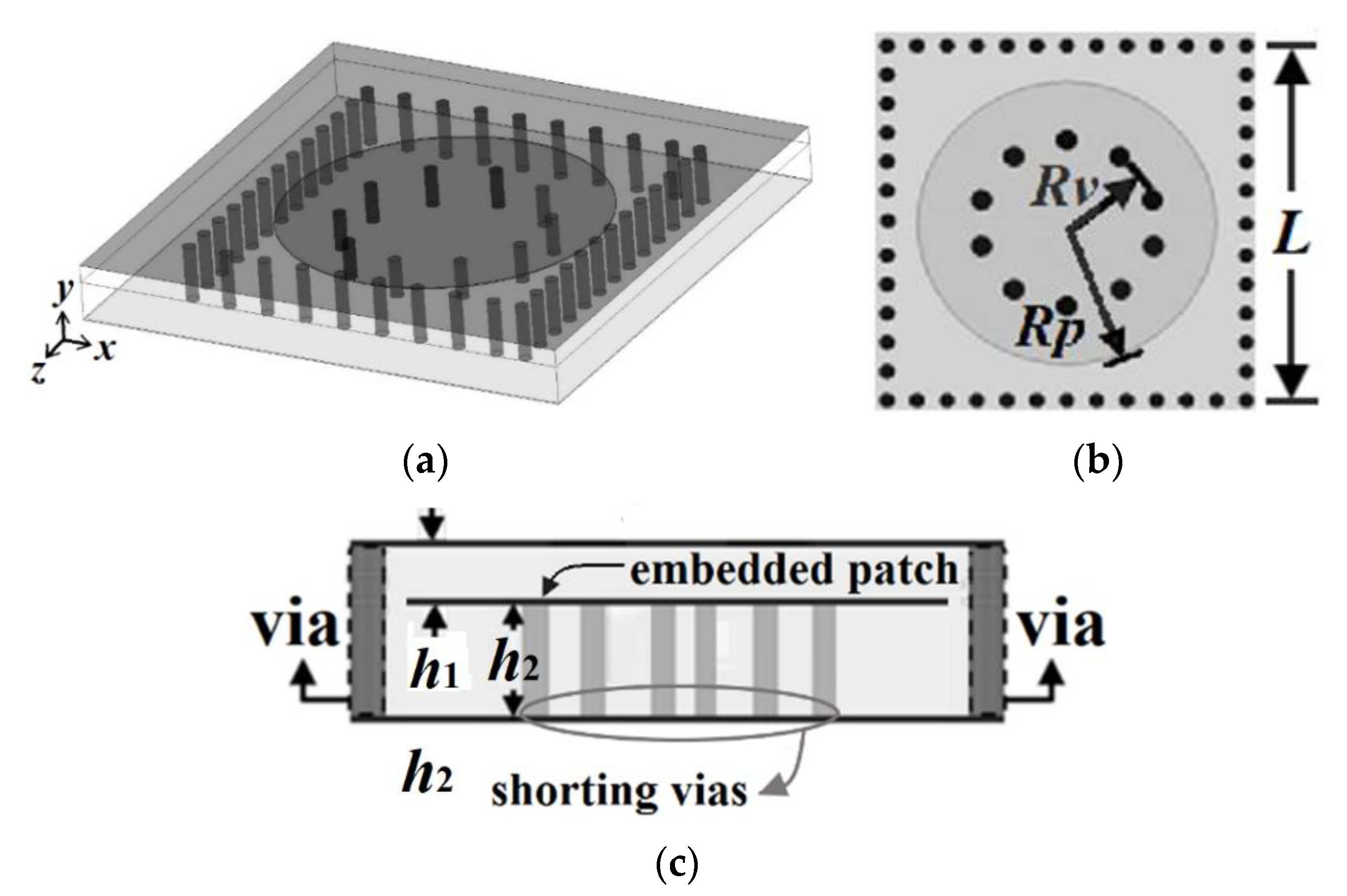
The proposed HMSICR is originated from the full-mode SICR given in Figure 1. This full-mode SICR is composed of three metal layers and two tightly stacked substrates with the same dielectric constant (εr) and loss tangent (tanδ). The thicknesses of the top and bottom substrates are denoted by h1 and h2, respectively. The cavity’s sidewalls are emulated by four periodically spaced thru-via arrays. The key point in miniaturizing the cavity is to reduce the cavity’s resonance frequency. This is accomplished by introducing a short-circuited circular metal patch in the cavity. The embedded circular patch is deployed in the middle layer (see Figure 1) and a circular array of blind vias is used to short the patch to the cavity’s bottom wall. The function of the embedded patch is to load the cavity with a large capacitance, which helps lower the resonance frequency [14,15]. It is expected that a cavity loaded with a larger capacitance will result in a lower resonance frequency. In Figure 2, we give the simulated normalized resonance frequency (fr/f0) and unloaded Q-factor (Qu) as functions of h1. In the simulation of this figure, the substrate is RT/duroid 5880 with εr = 2.2 and tanδ = 0.0009, which will also be adopted for our proposed HMSICR design. In addition, the metal sheets in the three metal layers all have the same thickness of 35 μm, the square cavity has a side length of L = 24 mm, the circular patch has a radius of Rp = 11 mm, the circular blind-via array has a radius of Rv = 5.5 mm, and the bottom substrate has a thickness of h2 = 1.58 mm. Here, fr is the resonance frequency of the full-mode SICR, and f0 = 5.97 GHz is the fundamental-mode (TE101-mode) resonance frequency of the conventional SIW cavity counterpart (i.e., the SIW cavity devoid of the circular patch and circular array of blind vias). It is observed from Figure 2 that a smaller value of h1 (corresponding to a larger loaded capacitance) leads to a lower resonance frequency. The fact that fr is much smaller than f0 indicates that the full-mode SICR structure can effectively miniaturize the SIW cavity resonator. Although the goal in lowering the resonance frequency is achieved in this structure, the drawback is that the full-mode SICR has a smaller Qu value than does its conventional SIW cavity counterpart having a Qu value of around 680. In Figure 3, we show the simulated curves of fr/f0 as functions of Rp and Rv. In the simulation, h1 is fixed at 0.254 mm, and other relevant structural parameters are the same as those used in the simulation of Figure 1. A larger value of Rp provides the cavity with a larger loaded capacitance and hence results in a lower resonance frequency. On the contrary, a larger value of Rv leads to a higher resonance frequency. This trend is opposite to that of the Rp variation and can be explained using a transmission-line model presented later for the HMSICR proposed in this section.
As shown in Figure 4, the proposed HMSICR is obtained by evenly bisecting the full-mode SICR given in Figure 1, and the layouts of the HMSICR’s three metal layers are given in Figure 5. The substrates adopted here are also RT/duroid 5880 and have the same thicknesses as those associated with Figure 3. Each of the blind vias has a diameter of 0.6 mm. The three thru-via arrays (also with a diameter of 0.6 mm for each via) mimic the three sidewalls of the cavity, and the fourth side of the cavity is open. The periodicity of the thru-via array is 2 mm. The open cavity in Figure 5 has the dimension of 12 × 24 mm2 (i.e., L = 24 mm in Figure 5).
Note that the full-mode SICR operates at a coaxial mode whose resonance-frequency expression developed from a transmission-line model can be found in [13]. Here, the HMSICR has one open side, which makes the field distribution under the semicircular patch slightly different from that of a coaxial-line mode. Hence, the expression needs to be modified to estimate the resonance frequency of the HMSICR. Figure 6 shows the side view of the HMSICR and the equivalent transmission-line model. The susceptance, B(ω), looking into the circular patch can be expressed as
with
Here, Cd represents the loaded capacitance between the semicircular patch and the top and bottom walls, and it can be approximated by with denoting the permittivity of the substrates. Note that since h1 is much smaller than h2 in our design, h1 predominates over h2 in determining the loaded capacitance. In addition, is the phase constant with c0 standing for the speed of light in free space, and Y0 in (2) is the characteristic admittance of the short-circuited half coaxial-line model in Figure 6b. Upon enforcing B(ω) = 0 in (1) together with the approximation of cot(βh2)1/βh2, the HMSICR’s resonance frequency, fr, can be approximated by
In Figure 7, we provide the normalized resonance frequency (fr/f0) and the unloaded Q-factor (Qu) as functions of Rp and Rv, which are simulated using the commercial software package, HFSS [16]. For comparison, the fr/f0 curves obtained using (2) and (3) are also plotted in Figure 7a. The reasonable agreement between the curves simulated using HFSS and those calculated using (2) and (3) implies that (2) and (3) are useful empirical expressions for estimating the resonance frequency of the proposed HMSICR structure. In these figures, Rv is fixed at 4 mm when Rp is varying, and conversely, Rp is fixed at 11 mm when Rv is varying. Note that the HMSICR proposed here and the full-mode SICR presented in [13] are found to have a similar trend in the resonance-frequency variation, i.e., the larger the patch and the smaller the semicircular via-ring, the lower the resonance frequency. In addition, the HMSICR has a smaller unloaded Qu than the full-mode SICR, which is because the former has larger conduction losses in the semicircular patch and the shorting vias.
3. Sample Results
Shown in Figure 8a is the 3-D view of the proposed sample BPF consisting of four HMSICRs. The four HMSICRs are divided into two identical HMSICR sets. Resonators 1 and 2 are side-by-side juxtaposed to form a set, and resonators 3 and 4 form the other. Figure 8b–d, respectively, show the layouts of the bottom, middle, and top metal layers of an HMSICR set. The two HMSICR sets are then vertically stacked in a back-to-back configuration. The vertical stacking of the HMSICRs is carried out by flipping one HMSICR set upside down and placing it on the top of the other HMSICR set. The coupling between the two side-by-side HMSICRs depends on the window embedded in the cavities’ common sidewall and the etched H-shaped slot on the cavity’s bottom wall. On the other hand, the coupling between the two vertically stacked HMSICRs (i.e., between resonators 1 and 4, or between resonators 2 and 3) depends on the three fan-shaped apertures etched on their common top metal wall and the nearby semicircular patches. The input and output HMSICRs (i.e., resonators 1 and 4) are each fed by an SMA probe from the bottom to the top wall of the cavity.
The coupling between the two side-by-side HMSICRs (i.e., between resonators 1 and 2, or between resonators 4 and 3) is dominated by the magnetic coupling which is controlled by the H-shaped slot etched on the cavities’ bottom wall. It should be noted that this magnetic coupling mainly depends on the induced currents flowing on the semicircular patch’s shorting vias, and the dimension of the open window (the window having a width of 6.8 mm indicated in Figure 8c) has a minor effect on the coupling strength. Therefore, we adopt an H-shaped slot to restrain the magnetic flux for controlling the coupling strength. Figure 9 shows the coupling coefficient between resonators 1 and 2 as a function of l (the width of the middle section of the H-shaped slot indicated in the inset). A larger coupling coefficient denotes a stronger coupling strength. In the coupling-coefficient calculation, the slot width and the height of the H-shaped slot are fixed at 1.5 and 11.5 mm, respectively. The coupling between the top and bottom HMSICRs depends on the fan-shaped apertures on the common broadside wall and the nearby semicircular patches. These apertures simultaneously introduce both electrical and magnetic couplings, whose corresponding coupling coefficients are negative and positive, respectively [17,18,19,20,21,22]. Note that the total coupling is the sum of the electrical and magnetic couplings, and the net coupling coefficient may be positive or negative. The employed HMSICRs possess two natural resonance frequencies, 1.85 and 1.92 GHz, respectively, for the left and right HMSICRs shown in Figure 8. The coupling coefficients (denoted by kij with the sub-indices i, j = 1, 2, 3, 4) are calculated to be k12 = k34 = 0.135, k24 = k13 = 0, k23 = 0.054, and k14 = –0.081, and the extracted external quality factor Qe is 14.3.
Figure 10 shows the measured and simulated frequency responses of the proposed BPF given in Figure 8. The zoom-in view around the passband region is also shown in this figure for clarity. Although compactly clustered, the four dips in the simulated S11 curve can still be distinguished. These four dips in the simulated S11 curve signify that the proposed BFP is a fourth-order design. However, from the measured S11 curve, we can hardly discriminate the four dips, and this might be due to the imprecise measurement resolution. This phenomenon can also be observed for the sample BPFs in [13]. The transmission zeros observed by the two passband edges are due to the well-known cross-coupling effect attributed to the circuit’s quadruplet topology [23,24,25,26]. The obtained measured (simulated) fractional BW (FBW) is 14.8% (14%) with the mid-band frequency of 1.81 (1.8) GHz. The measured (simulated) minimum in-band insertion loss (IL) is 0.6 (0.4) dB and the measured (simulated) TZs by the two passband edges are at the frequencies of 1.27 (1.22) and 2.28 (2.33) GHz.
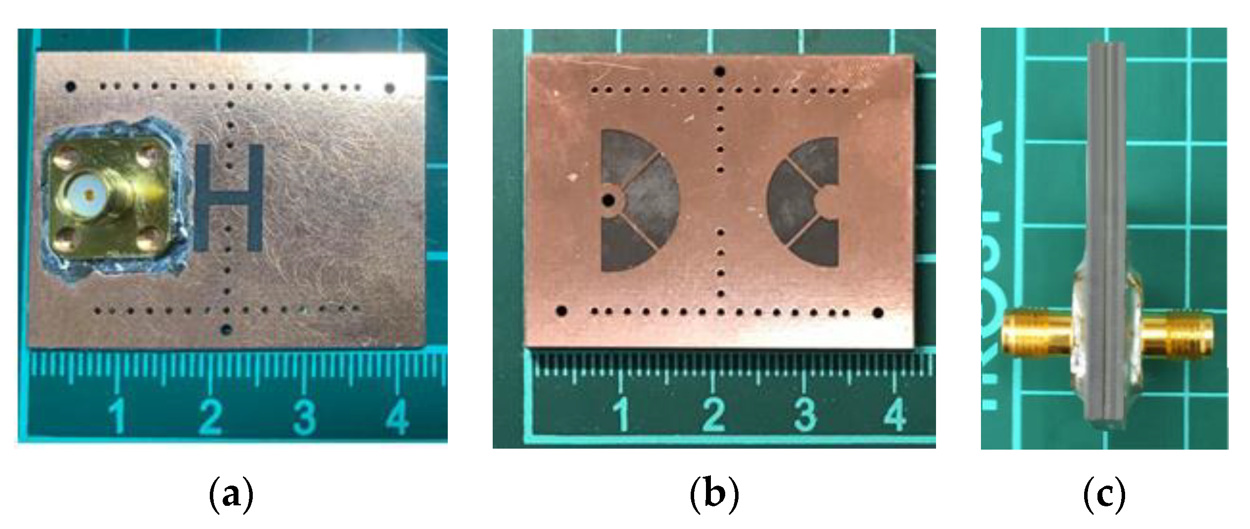
The circuit performance in terms of the mid-band frequency (fc), FBW, IL, upper stopband BW (USB BW), and especially the circuit size is summarized in Table 1 to compare with recent size-reduced SIW (or SIW cavity) BPFs. In the comparison table, our proposed fourth-order BPF occupies an area of only 0.24 λd × 0.22 λd with a maximum in-band IL of 0.6 dB and a FBW of 14.8%. Obviously, our BPF has a better size efficiency than other circuits in the table. Note that the fourth-order BPF in Figure 6 of [13] in Table 1 has a circuit size of only 0.26 λd × 0.26 λd, and the corresponding size efficiency is closest to ours. In that BPF, the patch is shorted to the bottom wall using only one blind via instead of a circular array of blind vias. Although this strategy is recognized to very efficiently lower the resonance frequency of an SIW cavity, the BPF in Figure 6 of [13] suffers a relatively high IL. This is because the conduction loss associated with the patch’s current flowing to the bottom wall through only a single blind via is larger than that through an array of blind vias. Photos of the experimental circuit in this paper are given in Figure 11.
4. Conclusions
In this paper, we present the miniaturized design of the half-mode substrate integrated coaxial resonator BPF. For a fourth-order SIW-related BPF, the one proposed here has achieved an excellent circuit-area efficiency since it occupies a circuit area of only 0.24 λd × 0.22 λd (physical dimensions of 27 × 24 mm2). The measured FBW is 14.8% with the minimum in-band IL of 0.6 dB. With such an excellent size-reduction achievement, the coaxial-mode-operated HMSICR BPF in this miniaturized design is believed very suitable for commercial wireless-communication applications.
Author Contributions
Conceptualization, M.-H.H.; methodology, M.-H.H., C.-I.G.H. and W.H.; software, K.-H.T.; validation, M.-H.H., C.-I.G.H. and K.-H.T.; formal analysis, M.-H.H., C.-I.G.H. and K.-H.T.; investigation, M.-H.H., C.-I.G.H., K.-H.T. and W.H.; resources, M.-H.H.; data curation, K.-H.T.; writing—original draft preparation, M.-H.H.; writing—review and editing, M.-H.H. and C.-I.G.H.; visualization, K.-H.T.; supervision, M.-H.H.; project administration, M.-H.H.; funding acquisition, M.-H.H. All authors have read and agreed to the published version of the manuscript.
Funding
This research was funded by Ministry of Science & Technology, R.O.C. under Grant contracts MOST 109–2221–E–018–018 and MOST 110–2221–E–018–005.
Data Availability Statement
The data presented in this study are available on request from the corresponding author.
Conflicts of Interest
The authors declare no conflict of interest.
References
- Marcuvitz, N. Waveguide Handbook; Peter Peregrinus Ltd.: London, UK, 1993. [Google Scholar]
- Piloto, A.; Leahy, K.; Flanick, B.; Zaki, K.A. Waveguide Filters Having a Layered Dielectric Structure. U.S. Patent 5,382,931, 17 January 1995. [Google Scholar]
- Hirokawa, J.; Ando, M. Single-layer feed waveguide consisting of posts for plane TEM wave excitation in parallel plates. IEEE Trans. Ant. Propagat. 1998, 46, 625–630. [Google Scholar] [CrossRef]
- Uchimura, H.; Takenoshita, T.; Fujii, M. Development of the “laminated waveguide”. In Proceedings of the IEEE MTT-S International Microwave Symposium Digest, Baltimore, MD, USA, 7–12 June 1998; pp. 2438–2443. [Google Scholar]
- Deslands, D.; Wu, K. Single-substrate integration technique of planar circuits and waveguide filters. IEEE Trans. Microw. Theory Tech. 2003, 51, 593–596. [Google Scholar] [CrossRef]
- Dong, Y.D.; Yang, T.; Itoh, T. Substrate integrated waveguide loaded by complementary split-ring resonators and its applications to miniaturized waveguide filters. IEEE Trans. Microw. Theory Tech. 2009, 57, 2211–2223. [Google Scholar] [CrossRef]
- Zhang, Q.-L.; Yin, W.-Y.; He, S.; Wu, L.-S. Compact substrate integrated waveguide (SIW) bandpass filter with complementary split-ring resonators (CSRRs). IEEE Microw. Wireless Compon. Lett. 2010, 20, 426–428. [Google Scholar] [CrossRef]
- Wang, Y.; Hong, W.; Dong, Y.; Liu, B.; Tang, H.J.; Chen, J.; Yin, X.; Wu, K. Half mode substrate integrated waveguide (HMSIW) bandpass filter. IEEE Microw. Wireless Compon. Lett. 2007, 17, 265–267. [Google Scholar] [CrossRef]
- Zhang, Z.; Yang, N.; Wu, K.K. 5-GHz bandpass filter demonstration using quarter-mode substrate integrated waveguide cavity for wireless system. In Proceedings of the IEEE Radio and Wireless Symposium, San Diego, CA, USA, 18–22 January 2009; pp. 95–98. [Google Scholar]
- Jin, C.; Shen, Z. Compact triple-mode filter based on quarter-mode substrate integrated waveguide. IEEE Trans. Microw. Theory Tech. 2014, 62, 37–45. [Google Scholar] [CrossRef]
- Martínez, J.D.; Sirci, S.; Taroncher, M.; Boria, V.E. Compact CPW-fed combline filter in substrate integrated waveguide technology. IEEE Microw. Wireless Compon. Lett. 2012, 22, 7–9. [Google Scholar] [CrossRef] [Green Version]
- Yang, T.; Ho, K.; Rebeiz, G.M. Compact self-shielded 2–3 GHz high-Q coaxial fixed and tunable filters. IEEE Trans. Microw. Theory Tech. 2014, 62, 3370–3379. [Google Scholar] [CrossRef]
- Ho, M.-H.; Li, J.-C.; Chen, Y.-C. Miniaturized SIW cavity resonator and its application in filter design. IEEE Microw. Wireless Compon. Lett. 2018, 28, 651–653. [Google Scholar] [CrossRef]
- Saghati, A.P.; Saghati, A.P.; Entesari, K. Ultra-miniature SIW cavity resonators and filters. IEEE Trans. Microw. Theory Tech. 2015, 63, 4329–4340. [Google Scholar] [CrossRef]
- Li, M.; Chen, C.; Chen, W. Miniaturized dual-band filter using dual-capacitively loaded SIW cavities. IEEE Microw. Wireless Compon. Lett. 2017, 27, 344–346. [Google Scholar] [CrossRef]
- High Frequency Structure Simulator (HFSS), version 21.0; ANSYS Inc.: Canonsburg, PA, USA, 2021.
- Chang, C.-Y.; Hsu, W.-C. Novel planar, square-shaped, dielectric-waveguide, single-, and dual-mode filters. IEEE Trans. Microw. Theory Tech. 2002, 50, 2527–2536. [Google Scholar] [CrossRef]
- Chen, X.-P.; Wu, K. Substrate integrated waveguide cross-coupled filter with negative coupling structure. IEEE Trans. Microw. Theory Tech. 2013, 61, 125130–125149. [Google Scholar] [CrossRef]
- Potelon, B.; Favennec, J.; Quendo, C.; Rius, E.; Person, C.; Bohorquez, J. Design of a substrate integrated waveguide (SIW) filter using a novel topology of coupling. IEEE Microw. Wirel. Compon. Lett. 2008, 18, 596–598. [Google Scholar] [CrossRef]
- You, C.J.; Chen, Z.N.; Zhu, X.W.; Gong, K. Single-layered SIW post-loaded electric coupling-enhanced structure and its filter applications. IEEE Tran. Microw. Theory Tech. 2013, 61, 125–130. [Google Scholar] [CrossRef]
- Shen, Y.-L.; Hung, J.-T.; Ho, M.-H.; Hsu, C.-I.G. Miniaturized substrate integrated waveguide cavities in dual-band filter and diplexer design. IET Microw. Ant. Propagat. 2020, 14, 428–434. [Google Scholar] [CrossRef]
- Ho, M.-H.; Tang, K.-H. Miniaturized SIW cavity tri-band filter design. IEEE Microw. Wireless Compon. Lett. 2020, 30, 589–592. [Google Scholar] [CrossRef]
- Hong, J.-S.; Lancaster, M.J. Microstrip Filters for RF/Microwave Applications; Chapters 10 & 11; John Wiley & Sons Inc.: New York, NY, USA, 2001. [Google Scholar]
- Kurzok, R.M. General four-resonator filters at microwave frequencies. IEEE Trans. Microw. Theory Tech. 1966, 14, 295–296. [Google Scholar] [CrossRef]
- Levy, R. Direct synthesis of cascaded quadruplet (CQ) filters. IEEE Trans. Microw. Theory Tech. 1995, 43, 2940–2944. [Google Scholar] [CrossRef]
- Hong, J.-S.; Lancaster, M.J. Compact microwave elliptic function filter using novel microstrip meander open-loop resonators. Electron. Lett. 1996, 32, 563–564. [Google Scholar] [CrossRef]
Figure 1.
The full-mode SICR: (a) the 3-D view, (b) top transparent view, and (c) side view.

Figure 2.
The simulated curves of normalized resonance frequency fr/f0 and Qu vs. the top substrate thickness h1 (with fixed h2 = 1.58 mm).
Figure 2.
The simulated curves of normalized resonance frequency fr/f0 and Qu vs. the top substrate thickness h1 (with fixed h2 = 1.58 mm).

Figure 3.
The simulated curves of the normalized resonance frequency fr/f0 vs. the dimension ratios of Rp/L and Rv/L (with fixed L = 24 mm).
Figure 3.
The simulated curves of the normalized resonance frequency fr/f0 vs. the dimension ratios of Rp/L and Rv/L (with fixed L = 24 mm).
Figure 4.
Evenly bisecting the full-mode SICR cavity to make the HMSICRs.
Figure 5.
The layouts of the three metal layers for the proposed HMSICR cavity.
Figure 6.
(a) The side view of the HMSICR; and (b) the equivalent transmission-line model for the susceptance looking into the embedded semicircular patch.
Figure 6.
(a) The side view of the HMSICR; and (b) the equivalent transmission-line model for the susceptance looking into the embedded semicircular patch.
Figure 7.
Simulated curves of (a) fr/f0 and (b) Qu vs. Rp (radius of the embedded patch) and Rv (radius of the semicircular via-ring).
Figure 7.
Simulated curves of (a) fr/f0 and (b) Qu vs. Rp (radius of the embedded patch) and Rv (radius of the semicircular via-ring).

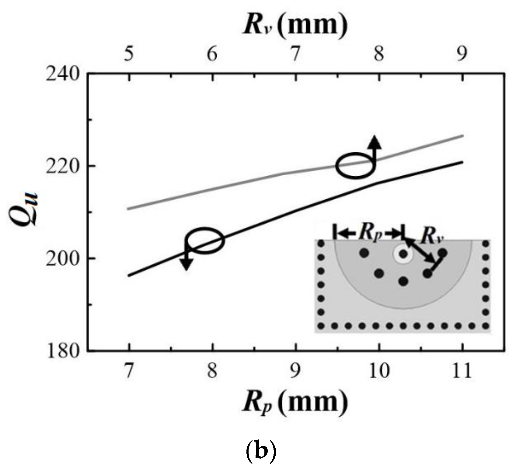
Figure 8.
The proposed HMSICR BPF structure: (a) the 3-D view; layouts of the (b) bottom; and (c) middle, and (d) top metal layers.
Figure 8.
The proposed HMSICR BPF structure: (a) the 3-D view; layouts of the (b) bottom; and (c) middle, and (d) top metal layers.
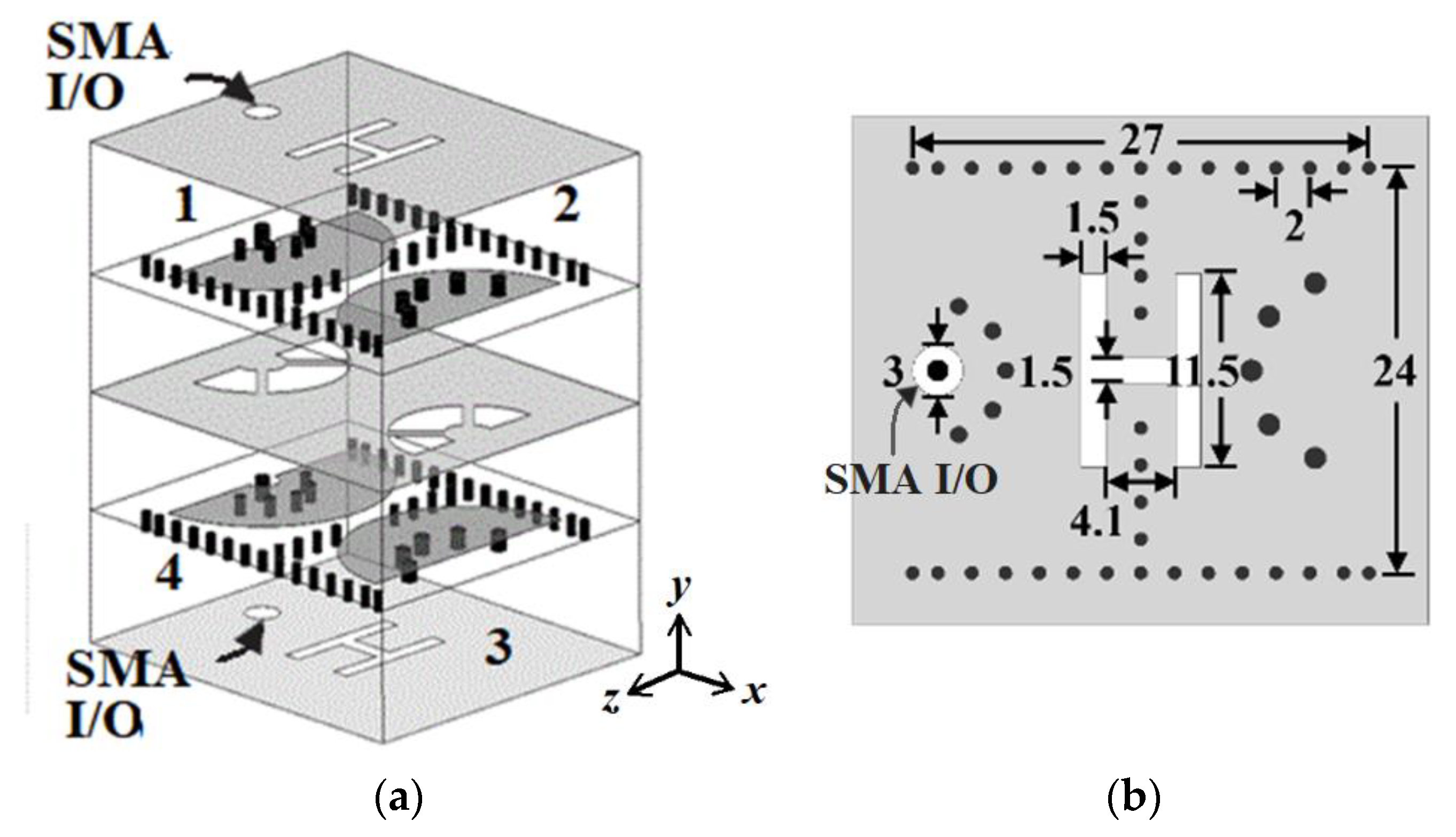
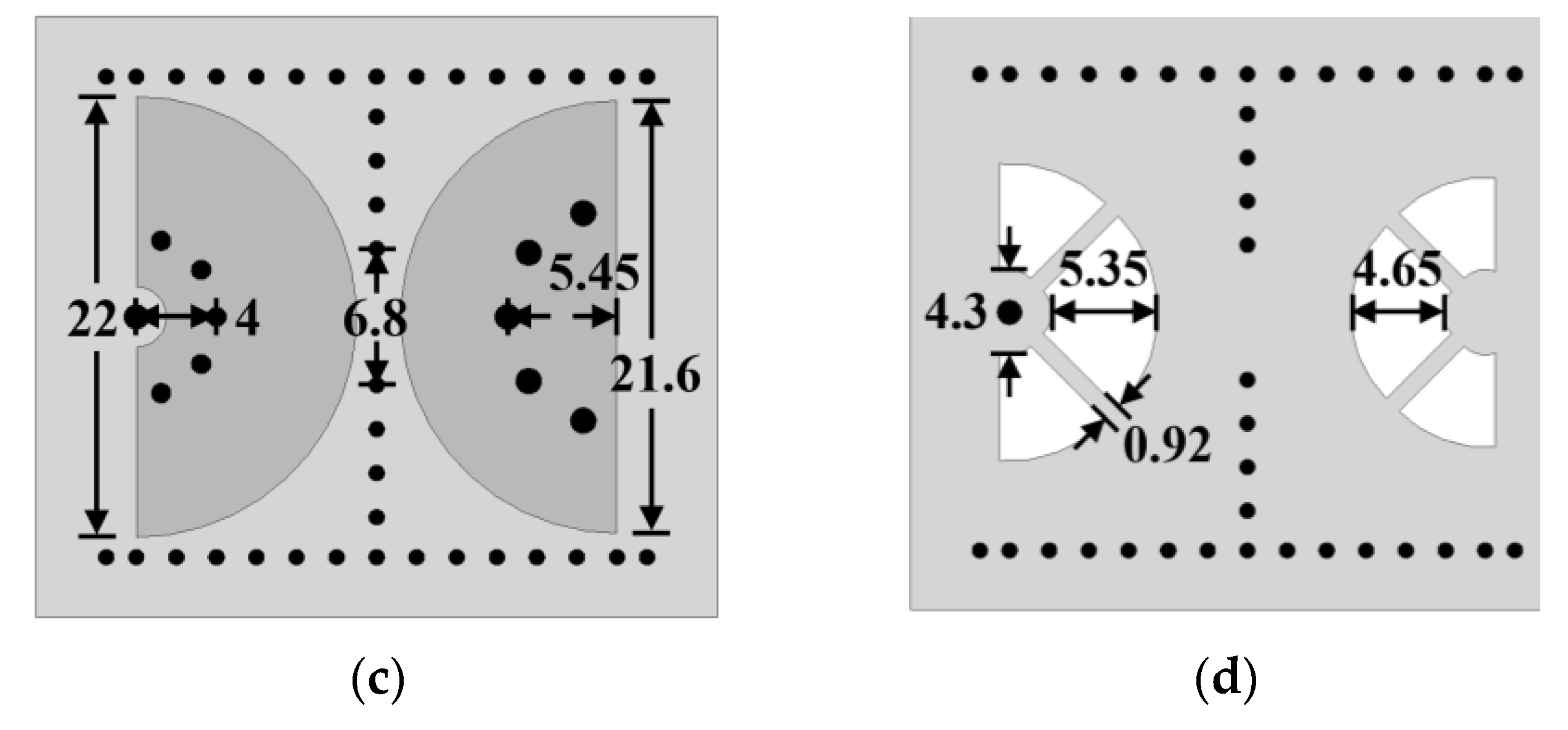
Figure 9.
The coupling coefficient between resonators 1 and 2 as a function of the dimension l in the H-shaped slot.
Figure 9.
The coupling coefficient between resonators 1 and 2 as a function of the dimension l in the H-shaped slot.

Figure 10.
The measured and simulated frequency responses for the proposed sample HMSICR BPF.
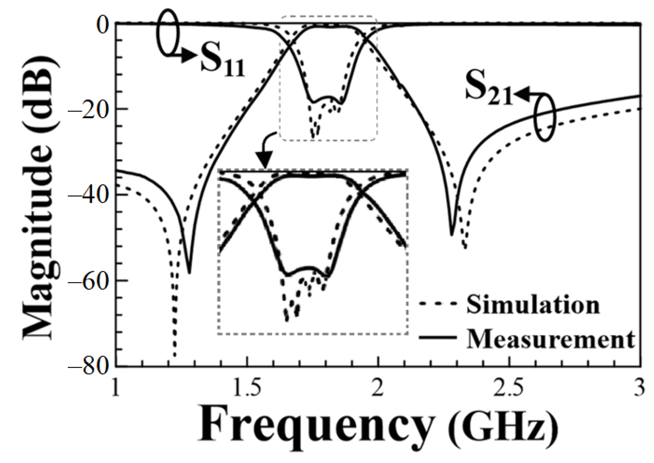
Figure 11.
Photos of the experimental circuit: (a) the top view with one of the feeding SMAs; (b) the layer containing the coupling apertures; and (c) the side view.
Figure 11.
Photos of the experimental circuit: (a) the top view with one of the feeding SMAs; (b) the layer containing the coupling apertures; and (c) the side view.

Table 1.
The measured circuit performance comparison.
| fc (GHz) | FBW (%) | IL (dB) | Circuit Order | Circuit Size (λd × λd) | USB BW (S21 ≤ –20 dB) | |
|---|---|---|---|---|---|---|
| [7] Figure 6 | 3.52 | 6.25 | 1.45 | 4 | 0.45 × 0.79 | |
| [8] Figure 2b | 8.79 | 40 | 1.2 | 5 | 1.15 × 0.33 | |
| [10] Figure 12 | 5.2 | 38 | 0.74 | 3 | 0.99 × 0.99 | |
| [12] Figure 6 | 3.58 | 6.5 | 1.7 | 3 | 0.35 × 0.47 | ~1.28 fc |
| [13] Figure 4 | 1.658 | 9.1 | 1.56 | 4 | 0.41 × 0.41 | 6.17 fc |
| [13] Figure 6 | 1.04 | 4.6 | 1.84 | 4 | 0.26 × 0.26 | 3 fc |
| This work | 1.81 | 14.8 | 0.6 | 4 | 0.24 × 0.22 | 0.4 fc |
λd: the intrinsic wavelength (defined by at frequency fc) in the dielectric medium.
Publisher’s Note: MDPI stays neutral with regard to jurisdictional claims in published maps and institutional affiliations. |
© 2022 by the authors. Licensee MDPI, Basel, Switzerland. This article is an open access article distributed under the terms and conditions of the Creative Commons Attribution (CC BY) license (https://creativecommons.org/licenses/by/4.0/).
Share and Cite
MDPI and ACS Style
Ho, M.-H.; Hsu, C.-I.G.; Tang, K.-H.; Hong, W. Miniaturized Band Pass Filter Design Using Half Mode Substrate Integrated Coaxial Resonators. Micromachines 2022, 13, 389. https://doi.org/10.3390/mi13030389
AMA Style
Ho M-H, Hsu C-IG, Tang K-H, Hong W. Miniaturized Band Pass Filter Design Using Half Mode Substrate Integrated Coaxial Resonators. Micromachines. 2022; 13(3):389. https://doi.org/10.3390/mi13030389
Chicago/Turabian StyleHo, Min-Hua, Chung-I G. Hsu, Kun-Hua Tang, and Wanchu Hong. 2022. "Miniaturized Band Pass Filter Design Using Half Mode Substrate Integrated Coaxial Resonators" Micromachines 13, no. 3: 389. https://doi.org/10.3390/mi13030389
Note that from the first issue of 2016, this journal uses article numbers instead of page numbers. See further details here.