
A Novel Remote-Controlled Vascular Interventional Robotic System Based on Hollow Ultrasonic Motor

State Key Lab of Mechanics and Control of Mechanical Structures, School of Aeronautics, Nanjing University of Aeronautics and Astronautics, Nanjing 210016, China
*
Author to whom correspondence should be addressed.
Micromachines 2022, 13(3), 410; https://doi.org/10.3390/mi13030410
Submission received: 19 February 2022
/
Revised: 27 February 2022
/
Accepted: 1 March 2022
/
Published: 4 March 2022
(This article belongs to the Special Issue Recent Advance in Piezoelectric Actuators and Motors)
Abstract
:Cardiovascular diseases (CVDs) are the deadliest diseases worldwide. Master-slave robotic systems have been widely used in vascular interventional surgery with the benefit of high safety, efficient operation, and procedural facilitation. This paper introduces a remote-controlled vascular interventional robot (RVIR) that aims to enable surgeons to perform complex vascular interventions reliably and accurately under a magnetic resonance imaging (MRI) environment. The slave robot includes a guidewire manipulator (GM) and catheter manipulator (CM) that are mainly composed of a hollow driving mechanism and a linear motion platform. The hollow driving mechanism is based on a traveling wave-type hollow ultrasonic motor (HUM) which has high positional precision, fast response, and magnetic interference resistance and realizes the cooperation of the guidewire and catheter by omitting the redundant transmission mechanism and maintaining good coaxiality. The HUM stator, the core part of the RVIR, is optimized by an adaptive genetic algorithm for better quality and greater amplitude of traveling waves, which are beneficial to the drive efficiency and precision. The robot system features great cooperating performance, small hysteresis, and high kinematic accuracy and has been experimentally verified for its capability to precisely manipulate the guidewire and catheter.
1. Introduction
CVDs that lead to heart attacks and strokes have been increasing in recent years. According to a survey of the World Health Organization, more than 17 million people are killed by CVDs every year [1,2]. Minimally invasive surgery has become the main treatment method for CVDs due to the advantages of smaller incisions, shorter recovery time, and less blood loss [3,4]. Traditional vascular interventional surgery has high risk [5,6], such as unavoidable physiological tremors during operation, and needs well-skilled surgeons who require a long period of professional training and rich clinical experience. Therefore, numerous studies have been conducted on the application and development of RVIRs which can replace manual intervention [6,7,8,9,10,11,12]. However, RVIRs need to use real-time imaging which can be obtained by an X-ray or MRI to direct the guidewire and catheter.
Future directions are towards MRI-compatible devices because MRI can offer excellent image contrast for cardiovascular soft tissues [6,13,14,15,16,17] and avoid exposing patients and clinicians to harmful radiation as generated by X-rays [12,18,19,20]; these benefits offer the potential to improve the therapy strategy and enhance procedure efficiency and outcome [21,22,23,24]. However, compatible MRI vascular interventional master-slave robotic systems are only in their infancy. Lee et al. [12] developed a hydraulically driven vascular interventional robot system using distilled water as the transmission medium. The linear and twist motion of the catheter was realized by a piston and gear-rack mechanism. Abdelaziz et al. [6] developed a pneumatic driven vascular interventional delivery mechanism which adopts a pneumatic linear stepper motor and pneumatic rotary stepper motor to realize linear motion and rotary motion of the guidewire and catheter, respectively. Compared with a pneumatic drive, the incompressibility of liquid in the hydraulic drive is significantly better than that of gas, thus providing a more stable transmission and faster response. However, because the hydraulic driven device adopts a gear-rack mechanism to transfer the motion form, it brings the motion lag problem caused by gear clearance. In order to reduce the gear backlash, it is necessary to increase the pre-pressure exerted by hydraulic transmission on the gear, but this may lead to severe friction on the gear and pivot, which reduces the operating accuracy. In addition, hydraulic and pneumatic drives need electromagnetic motors to provide the remote power supply, in order to avoid the adverse effects of an electromagnetic motor on MRI imaging. The long-distance (>10 m) power transmission may cause large pressure loss and driving lag. This hysteresis phenomenon will significantly affect the performance of the robot system and would make it difficult to meet the high precision requirements of vascular interventional surgery. Tavallaei et al. [25] proposed an MRI-compatible remote catheter navigation system with 3 degrees of freedom which can realize the axial, rotation, and plunger actuation motion of the catheter by an ultrasonic motor, differential gear mechanism, rotating gantry, and winch-spring mechanism. This robotic system has a complex structure and contains a large number of intermediate transmission mechanisms which makes it difficult to achieve high-precision motion control. Liu et al. [26] presented the three-dimensional kinematic modeling of a steerable robotic ablation catheter system. The catheter, embedded with a set of current-carrying micro-coils, can realize the deflection motion by the magnetic force generated by the magnetic field of the MRI scanner. However, this driving method can only be used to drive the catheter to achieve a single bending deformation and cannot realize the axial and rotary motion, so it is difficult to be applied in vascular interventional surgery.
In addition, for complex vascular interventional surgery, such as cerebrovascular and vascular tumor surgery, the application of an active catheter that can rotate its guiding tip is greatly limited due to its size and safety problems [27,28]. Therefore, this surgery needs a surgeon to operate the passive catheter and guidewire simultaneously. In the vicinity of narrow vessel branches, the guidewire and passive catheter need to be pushed, pulled, and rotated to get them into the correct path; this operation process requires the cooperation of the guidewire and passive catheter. However, the full cooperation of the guidewire and catheter is rarely able to be realized due to the design limitations at present. For example, the long transmission chains of traditional robotic systems make catheters and guidewire difficult to meet the coaxial requirement, which may affect the cooperation accuracy [27] and cause additional wear. The Amigo, Corpath200, and Sensei Robotic Catheter Systems can only control the guidewire or catheter individually [29,30,31,32]. Srimathveeravalli et al. developed a robotic system that controls catheters with a mobile device and actuates the guidewire with friction wheels [33]. This drive mode may cause the guidewire to slip so that the slave robot cannot accurately replicate the movement of the master robot. Bao et al. developed a robotic system that adopts wire rope and gear as a linear and rotary driving device of guidewires and catheters [27]. However, the cable ropes are prone to generate stress and break at the bend and the gear transmission mechanism may affect the movement accuracy and cause pollution.
In order to obtain high motion accuracy, fast response, great cooperation performance, and MRI environment compatibility, piezo ultrasonic motors [34,35,36,37] can be implemented in RVIR systems. This paper proposes a novel RVIR based on a HUM and linear ultrasonic motor (LUM) which are not subject to electromagnetic interference and have the characteristic of rapid responsibility and high positional accuracy. In addition, using a HUM to drive the guidewire (0.014 inch, Nickel Titanium Alloy) and catheter (5 Fr, PVC) directly can eliminate the long transmission mechanism and ensure the catheter and guidewire have a good coaxial performance during surgery. As the core part of RVIR, a HUM was designed in detail and optimized. The structure of the slave robot and master robot are discussed in Section 2. The design and optimization of the HUM are analyzed experimentally and theoretically in Section 3. The key performances of RVIR, such as motion accuracy, master-slave tracking ability, and cooperative operation reliability, were tested and the results evaluated in Section 4.
2. System Design
2.1. Working Principle of RVIR
Figure 1 illustrates the working principle of the proposed RVIR. The master robot and slave robot are placed outside and inside the operating room, respectively, during surgery. On the master side, the rotary motion and linear motion of the guidewire manipulated by the surgeon are acquired and transmitted to the control unit (STM32F429IGT6, STMicro Co., Geneva, Switzerland) which drives the slave robot to control the guidewire and catheter to move in the blood vessel. The positional information of the guidewire and catheter is detected by MRI and the surgeon uses the imaging as visual feedback to proceed with the next motion.
2.2. Slave Robot Design
As shown in Figure 2a, the slave robot mainly includes the GM and CM. The two manipulators are composed of a hollow mechanism and linear motion platform, shown in Figure 2b,c, that can drive the guidewire and catheter to rotate and deliver. In order to transfer the rotary motion of the HUM to the guidewire and catheter and realize precise positioning, a screw clamping mechanism was designed. The clamping mechanism uses a V-shaped block to position the guidewire and catheter and utilizes an ultrasonic motor to drive the screw nut to implement clamping. The linear motion platform can realize the linear motion of the guidewire and catheter by using the LUM to drive two hollow mechanisms. The rotation angle and linear displacement of guidewire and catheter were detected by a hollow encoder (HKT5612-301G-2000BZ1-5L, Rep-Avago Electronic Technology Co., Ltd., Wuxi, China) and grating ruler (SX-520-5-A, Fagor Automation Co., Ltd., Beijing, China), respectively, which can be used in MRI environment.
The hollow mechanism and LUM can directly transfer rotation motion and linear motion to the guidewire and catheter, avoiding the complex transmission structure and long-distance transmission channel, which can significantly improve the accuracy and response speed of master-slave tracking motion. At the same time, the direct-driven method and the positioning of the clamping mechanism can make the guidewire and catheter have good coaxiality during operation, which is conducive to cooperative control.
2.3. Master Robot Design
As shown in Figure 3, the master robot is a platform for the surgeon to operate during surgery. The linear motion and rotary motion of the master robot can be transferred to the slave robot through sensors and controllers to complete the corresponding operation. Considering the operation habit of the surgeon, a guidewire was introduced into the master robot as the control object.
The surgeon realizes the rotary motion and linear delivery motion of the guidewire in the master robot by rotating the guidewire adapter and moving the linear slider. The incremental rotary encoder (ZSP5208-001G-5000BZ1-5F, Ningbo fangjiaoshi Electrical Equipment Co., Ltd., Ningbo, China) and slider-type linear displacement sensor (1800110250A20, Germanjet Co., Ltd., Shenzhen, China) were used to record the rotary angle and displacement. The button switch was designed to select the guidewire or catheter in the slave robot as the control object.
3. Design and Optimization of the HUM
3.1. The Structure and Motion Mechanism of the HUM
Although there are many kinds of HUMs at present, if they are directly applied to RVIR, they will cause structural complexity and difficulty in meeting operating requirements. Therefore, we designed the HUM which is used in RVIR independently. The structure of the HUM is shown in Figure 4a,b. The HUM stator is fastened to the base by a stator lock nut and the stator, and the rotor is pressed together by a lock nut. As shown in Figure 4c, the HUM stator has two orthogonal modal shapes A and B and it can be expressed as:
where R(r) is the transverse displacement distribution function along the radial direction, sin(nθ) and cos(nθ) are the displacement distribution functions along the circumferential direction, and n is the number of nodal lines (n = 11 in this paper). When two-phase voltages are applied to the two-phase piezoelectric ceramic (PZT), respectively, and the interference modes are not considered, the two-phase A and B standing waves can be written as:
where WA and WB are the amplitudes of phase A and B standing waves, α is the phase difference between the two-phase responses. If the two-phase voltages are applied at the same time, according to the superposition principle, the displacement response of the stator is
when α = ±π/2 and WA = WB = W0, Equation (3) becomes the forward and backward traveling wave:
where W0 is the amplitude of the traveling wave. The traveling wave can make points on the stator from the ellipse motion trajectory which produces the rotation of the HUM rotor and then drives the guidewire and catheter, which are clamped, to rotate.
3.2. Optimization of the HUM
As the rotary driving mechanism of the guidewire and catheter, the mechanical properties of the HUM will significantly affect the control accuracy of RVIR. So, the adaptive genetic algorithm [38,39] which can obtain the approximate optimal solution in the whole domain was adopted to optimize the stator of the HUM for better performance. The optimization analysis process is shown in Table 1.
Based on engineering experience and actual processing conditions, seven structure parameters of the HUM stator were selected as design variables, as shown in Figure 5, and the initial size and design space of each design variable was presented in Table 2.
The structure optimization of the HUM stator is mainly faced with four design requirements. The objective functions and constraint condition of optimization analysis can be obtained by describing each requirement mathematically:
(1) The two working mode frequencies, FA and FB, should be as far away as possible from the frequencies of the two front and rear interference modes, Ff and Fb. If the frequency of interference modes is close to that of working modes, the interference modes may be excited when two-phase voltages are applied. According to the superposition principle, the stator surface will produce an irregular motion pattern instead of an ideal traveling wave, which will reduce the stability and efficiency of motor operation, and thus reduce the motion accuracy of the guidewire and catheter. Therefore, the objective function G1 can be expressed as:
(2) Increasing the amplitude of the traveling wave can more easily push the rotor and improve the efficiency of the HUM, so the objective function G2 can be set as:
(3) The stress value of the stator inner ring should be as small as possible, otherwise, the vibration of the stator may be excessively limited by the fixed constraint, which will also reduce the motion precision of the HUM. The objective function G3 can be described as:
(4) σres and σvib which are the maximum stress value of stator at rest and vibration should be less than yield stress σs. The optimization constraint can be expressed as follows:
The multi-objective optimization problem can be converted into a single-objective optimization problem by combining multiple optimization objective functions into a total objective function G with linear weighting method, the expression can be written as:
where P = [P1,P2,P3,P4,P5,P6,P7]T is the design variable vector, βi are the weight coefficients of each sub-objective function. In order to make the terms of objective function G dimensionless and have similar weight, the weight coefficients are set as:
According to the above analysis, the stator optimization model can be described as follows:
where Pilb and Piub are the lower and upper bounds of each design variable.
In order to improve the construction accuracy of response surface and sampling efficiency, the Latin hypercube random sampling method, which can make the sample points distribute evenly and cover the whole design space, was adopted. The sampling method is described in detail as follows:
In this paper, there are M = 7 design variables in total, and each design variable is assumed to follow a normal distribution. The mathematical expectation and standard deviations are the initial sizes and 1, respectively. The cumulative distribution function is Fi(Pi) and the total sampling times were N = 40. Firstly, the sampling situation of design variable Pi is considered, and the interval [0,1] is divided into N sub-intervals. Random sampling is carried out in each sub-interval, and the original sampling value in the kth interval can be obtained as follows:
where random variable u is uniformly distributed on [0,1], and the final sample value Pik corresponding to design variable Pi is:
Random sorting of Pik collected for N times can obtain the random sampling vector P′i = [P′i1, P′i2, …, P′iN]T which represents the N sampling values of design variable Pi. The random sampling vector of other design variables can be obtained in the same way.
Based on the above analysis, enough reasonable sample points were brought into the finite element model for analysis to be obtained. The response surface model was established after unreasonable sample points were filtered out according to the optimization constraint. The relationship between optimization objective function G and design variable vector P can be expressed as:
where f(P) is the target approximation function used to describe response surface, ε and m are the statistical error and the number of basis functions, respectively, and αi and ϕi(P) are the fitting coefficients and basis functions.
Considering the nonlinearity and analysis efficiency of the problem comprehensively, f(P) is described by a third-order polynomial:
The following equation can be obtained according to the least square principle:
where Pj and εj are the design variable vector and statistical error of the jth sampling. α = [α1,α2,…,αm]T is the undetermined regression coefficient vector. Φ and G are the basis function matrix and real response vector which can be expressed as:
According to Equations (16) and (17), α = (ΦTΦ)−1ΦTG can be solved and the response surface model can be further obtained. However, f(P) includes a large number of design variables, high order terms, and cross terms, and its complexity makes analysis inefficient. Therefore, we get the contribution rate of each basis function to the target approximation function through sensitivity analysis, and use the objective function with a large contribution rate to construct the final response surface:
where A = P2, B = P6, C = P7, D = P6P7, E = P62, F = P1P4P6, G = P3P5P6, H = P4P5P6, I = P12P4, J = P22P6, K = P52P1, L = P52P6, and M = P62P2, N = P62P5, O = P63. Figure 6 is the contribution rate of the basis functions which are used to construct the final response surface model.
The error determination coefficient is 94.5% which can illustrate the constructed response surface is able to describe the relationship between the optimization objective function G and the design variable vector P accurately. Through the adaptive genetic algorithm optimization analysis, we can obtain the optimized design variable vector Pf is [0.83, 2.37, 2.4, 4.15, 0.55, 1.61, 1.35]T. The frequency differences between the working modes and the interference modes are 2.21 kHz and 1.91 kHz, which are much larger than the 0.43 kHz and 1.37 kHz under the initial design variable vector Pi= [0.9, 2.5, 2.5, 4.5, 0.5, 1.5, 1.5]T. The interference modes of the optimized stator are far away from the working modes so the traveling wave can have better quality. The amplitude of the traveling wave is increased by nearly 3.5 times from 0.81 mm to 2.79 mm and the inner ring stress decreased from 15.23 Mpa to 11.17 Mpa. The result of FEA is verified by a vibration measurement experiment on the doppler 3D laser vibration measuring instrument as shown in Figure 7. The initial and optimized results are compared in Table 3.
4. Experimental Performance Evaluation
4.1. Experimental Platform and Control Algorithm
In order to test the motion accuracy, verify master-slave tracking performance and cooperation performance, and simulate the vascular intervention process, four test experiments were conducted on the RVIR platform as shown in Figure 8. This section will describe the experimental methods and results of each test experiment in detail.
Although the standard incremental PID control algorithm can eliminate the static error, the system will have a large overshoot at the initial stage of starting, so that the system may oscillate which will reduce the driving accuracy. As shown in Figure 9, the incremental integral separation PI algorithm was adopted to control the rotary motion of the guidewire and catheter in this paper. The master robot is used to determine the ideal position and the motor speed increment is calculated according to the position deviation through the PI algorithm. The driving frequency is determined by the frequency characteristic curve of the HUM, which is used as the input signal to adjust the rotation speed of the HUM through the actuator. When the position deviation is greater than the threshold value, the integrator will be canceled to avoid large overshooting and improve the response speed of the system. When the position deviation is small, the integrator is introduced to eliminate the static error and ensure the control accuracy of the system. The LUM adopted the same control algorithm to drive the GM and CM.
For rotary motion and linear motion, the threshold values are 5° and 2 mm, the proportional coefficient is 0.05 and 1.5, the integral coefficient is 0.05 and 1, respectively, and the sampling period is 20 ms.
4.2. Slave Robot Driving Accuracy Test Experiment
The motion of the HUM and LUM was directly controlled by the upper computer, instead of using a master-slave control algorithm, to verify the driving accuracy of the GM and CM in the slave robot. According to clinical experience, the GM and CM performed rotary motion and linear motion 20 times; each rotation angle and displacement distance were 30° and 25 mm and the speed of rotary motion and linear motion were 50°·s−1 and 20 mm·s−1, respectively. The motion errors of the GM and CM are shown in Table 4.
The experimental results show that the slave robot has good driving precision, the rotating motion accuracy, especially, of the GM and CM was very high and is far higher than the cable-driven mechanism [27], fully demonstrating the great advantage of applying the HUM to the structure design of RVIR in this study.
4.3. Master-Slave Tracking Test Experiment
The master-slave tracking test was carried out to verify the control accuracy of the incremental integral separation PI control algorithm for RVIR. In order to verify the master-slave tracking ability of the GM and CM, eight linear motion and rotary motion tests were carried out, respectively. Taking the linear motion of the GM as an example, the linear motion of the GM was carried out by master-slave control mode many times. The master-slave tracking trajectories in the experimental process were recorded by sensors, and the motion errors of each experiment were calculated, as shown in Figure 10. The same method was used to test the master-slave performance of the rotary motion and the CM.
The result shows that the motion trajectories of the GM and CM in slave robots are basically consistent with the master robot. The tracking errors of the GM and CM are less than 0.3 mm and 0.15°, and the master-slave tracking lag time of the GM and CM is less than 200 ms. The results show that using incremental integral separation PI control algorithm to drive the HUM and LUM can make RVIR have good control accuracy and high response speed.
4.4. Cooperative Control Motion Test Experiment
Complex vascular interventional surgery requires the cooperation of the guidewire and catheter, and the alternating linear motion and alternating rotary motion of guidewire and catheter are the main motion modes during the process of cooperative operation. So, this paper mainly studied the coupling degree of linear-linear motion and rotary-rotary motion between guidewire and catheter. Firstly, using the master-slave control mode to drive the GM to move a certain distance and then to drive the CM to move a certain distance. This process was repeated many times, and the linear motion tracking trajectories and linear motion errors of the GM and CM during the cooperation process was obtained as shown in Figure 11a,b. The test method of rotary motion is similar and the results are shown in Figure 11c,d.
Experimental results show that the linear motion and rotary motion errors are less than 0.4 mm and 0.2°, respectively, and the master-slave tracking lag time is less than 300 ms. Although the master-slave tracking errors and lag time during cooperating are greater than that in the master-slave tracking test experiment, the results are very close. The results indicate that there is no obvious motion coupling between the GM and CM, and RVIR can still maintain high motion accuracy during cooperation.
4.5. Vascular Intervention Simulation Experiment
In order to verify that RVIR can perform complex vascular interventional surgery, the simulation experiment was carried out. As shown in Figure 12a–d, the operator controlled the master robot to make the GM and CM drive the guidewire and catheter from their initial position, pass through two vessel branches, and finally reach the target position. Figure 12e,f shows the linear and rotary motion of the GM and CM. In this experiment, multiple experimenters were selected for operating to avoid contingency. The whole movement process of guidewire and catheter is clearly presented in the attached video.
The result shows that the experimenters were able to control the robot to successfully complete the vascular intervention simulation test, with the average operation time and maximum operation time of 161 s and 195 s, respectively, which demonstrates that RVIR has reliable and stable operation.
5. Conclusions and Future Work
In this paper, we proposed a novel RVIR that can complete complex vascular interventional surgery. A HUM and LUM were used to directly drive the guidewire and catheter which eliminated the redundant transmission mechanism in the traditional structure. At the same time, this RVIR enables the guidewire and catheter to maintain good coaxiality during surgery, which is beneficial to the cooperation. In addition, an adaptive genetic algorithm was used to optimize the stator of the HUM, so that the stator can produce more ideal traveling waves and significantly increase the amplitude of the traveling wave, which is conducive to improving the driving performance of the HUM. Finally, a slave robot driving accuracy test experiment, master-slave tracking test experiment, cooperative control motion test experiment, and vascular intervention simulation experiment were carried out to verify that the RVIR has good control accuracy, high master-slave tracking performance, and great cooperative control performance. In the future, we will conduct performance test experiments and vascular intervention simulation tests under an MRI environment to fully verify the great MRI compatibility of RVIR. Furthermore, the LUM will be optimized to further improve the linear motion accuracy of the GM and CM.
Author Contributions
Conceptualization, Q.L., Z.S. and J.Z. (Juju Zheng); methodology, Q.L. and Z.S.; software, J.Z. (Juju Zheng); writing—original draft preparation, Q.L.; writing—review and editing, J.Z. (Jialiang Zhang), J.Z. (Jiacheng Zhang) and F.Q.; funding acquisition, Z.S. All authors have read and agreed to the published version of the manuscript.
Funding
This research was funded by [The National Natural Science Foundation of China] grant number [51775274].
Conflicts of Interest
The authors declare no conflict of interest.
References
- Guo, J.; Guo, S.; Xiao, N.; Ma, X.; Kawanishi, M. A novel robotic catheter system with force and visual feedback for vascular interventional surgery. Int. J. Mechatron. Autom. 2012, 2, 15–24. [Google Scholar] [CrossRef] [Green Version]
- Bian, G.B.; Xie, X.L.; Feng, Z.Q.; Hou, Z.G.; Tan, M. An enhanced dual-finger robotic Hand for Catheter manipulating in vascular intervention: A preliminary study. In Proceedings of the IEEE International Conference on Information & Automation, Yinchuan, China, 27 January 2014. [Google Scholar]
- Miller, D.L. Why use remote guidance to steer catheters and guide wires? Radiology 2004, 232, 313. [Google Scholar] [CrossRef] [PubMed] [Green Version]
- Beyar, R.; Gruberg, L.; Dan, D.; Roguin, A.; Almagor, Y.; Cohen, S.; Kumar, G.; Wenderow, T. Remote-control percutaneous coronary interventions: Concept, validation, and first-in-humans pilot clinical trial. J. Am. Coll. Cardiol. 2006, 47, 296–300. [Google Scholar] [CrossRef] [PubMed] [Green Version]
- Tanimoto, M.; Arai, F.; Fukuda, T.; Itoigawa, K.; Hashimoto, M.; Takahashi, I.; Negoro, M. Telesurgery System for Intravascular Neurosurgery. In Proceedings of the International Conference on Medical Image Computing & Computer-Assisted Intervention, Berlin, Germany, 11 October 2000. [Google Scholar]
- Abdelaziz, M.; Stramigioli, S.; Yang, G.Z.; Kundrat, D.; Riga, C. Toward a Versatile Robotic Platform for Fluoroscopy and MRI-Guided Endovascular Interventions: A Pre-Clinical Study. In Proceedings of the 2019 IEEE/RSJ International Conference on Intelligent Robots and Systems (IROS), Macau, China, 4–8 November 2019. [Google Scholar]
- Shang, W.; Hao, S.; Gang, L.; Fischer, G.S. Teleoperation System with Hybrid Pneumatic-Piezoelectric Actuation for MRI-Guided Needle Insertion with Haptic Feedback. In Proceedings of the IEEE/RSJ International Conference on Intelligent Robots & Systems, Tokyo, Japan, 3–7 November 2013. [Google Scholar]
- Yang, X.; Wang, H.; Sun, L.; Yu, H. Operation and Force Analysis of the Guide Wire in a Minimally Invasive Vascular Interventional Surgery Robot System. Chin. J. Mech. Eng. 2015, 28, 249–257. [Google Scholar] [CrossRef]
- Rafii-Tari, H.; Payne, C.J.; Yang, G.Z. Current and Emerging Robot-Assisted Endovascular Catheterization Technologies: A Review. Ann. Biomed. Eng. 2014, 42, 697–715. [Google Scholar] [CrossRef] [PubMed]
- Lin, J.C. The role of robotic surgical system in the management of vascular disease. Ann. Vasc. Surg. 2013, 27, 976–983. [Google Scholar] [CrossRef]
- Liu, D.; Zhang, D.; Wang, T. Overview of the vascular interventional robot. Int. J. Med. Robot. Comput. Assist. Surg. 2010, 4, 289–294. [Google Scholar]
- Lee, K.H.; Fu, K.; Guo, Z.; Dong, Z.; Leong, M.C.W.; Cheung, C.L.; Lee, P.W.; Luk, W.; Kwok, K.W. MR Safe Robotic Manipulator for MRI-guided Intra-cardiac Catheterization. IEEE/ASME Trans. Mechatron. 2018, 23, 586–595. [Google Scholar] [CrossRef]
- Wijnmaalen, A.P.; van der Geest, R.J.; van Huls van Taxis, C.F.; Siebelink, H.M.J.; Kroft, L.J.; Bax, J.J.; Reiber, J.H.; Schalij, M.J.; Zeppenfeld, K. Head-to-head comparison of contrast-enhanced magnetic resonance imaging and electroanatomical voltage mapping to assess post-infarct scar characteristics in patients with ventricular tachycardias: Real-time image integration and reversed registration. Eur. Heart J. 2011, 32, 104–114. [Google Scholar] [CrossRef] [Green Version]
- Radau, P.E.; Pintilie, S.; Flor, R.; Biswas, L.; Wright, G.A. VURTIGO: Visualization Platform for Real-Time, MRI-Guided Cardiac Electroanatomic Mapping. In Proceedings of the International Workshop on Statistical Atlases & Computational Models of the Heart, Berlin, Germany, 22 September 2011. [Google Scholar]
- Lardo, A.C.; Mcveigh, E.R.; Jumrussirikul, P.; Berger, R.D.; Calkins, H.; Lima, J.; Halperin, H.R. Visualization and Temporal/Spatial Characterization of Cardiac Radiofrequency Ablation Lesions Using Magnetic Resonance Imaging. Circulation 2000, 102, 698–705. [Google Scholar] [CrossRef] [Green Version]
- Ranjan, R.; Kholmovski, E.G.; Blauer, J.; Vijayakumar, S.; Volland, N.A.; Salama, M.E.; Parker, D.L.; MacLeod, R.; Marrouche, N.F. Identification and Acute Targeting of Gaps in Atrial Ablation Lesion Sets Using a Real-Time Magnetic Resonance Imaging System. Circ. Arrhythmia Electrophysiol. 2012, 5, 1130–1135. [Google Scholar] [CrossRef] [Green Version]
- Zia, M.I.; Ghugre, N.R.; Connelly, K.A.; Strauss, B.H.; Sparkes, J.D.; Dick, A.J.; Wright, G.A. Characterizing myocardial edema and hemorrhage using quantitative T2 and T2* mapping at multiple time intervals post ST-segment elevation myocardial infarction. Circ. Cardiovasc. Imaging 2012, 5, 566–572. [Google Scholar] [CrossRef] [Green Version]
- Linet, M.S.; Kim, K.P.; Miller, D.L.; Kleinerman, R.A.; Simon, S.L.; Gonzalez, A.D. Historical review of occupational exposures and cancer risks in medical radiation workers. Radiat. Res. 2010, 174, 793–808. [Google Scholar] [CrossRef] [Green Version]
- Yoshinaga, S.; Mabuchi, K.; Sigurdson, A.J.; Doody, M.M.; Ron, E. Cancer risks among radiologists and radiologic technologists: Review of epidemiologic studies. Radiology 2004, 233, 313–321. [Google Scholar] [CrossRef]
- Ramanathan, V.; Almeida, S.M.; Fernando, K. Occupational dose measurement for radiographers during cardiac catheterization procedures. Int. J. Sci. Res. Publ. 2021, 11, 476. [Google Scholar] [CrossRef]
- Bhagirath, P.; van der Graaf, M.; Karim, R.; Rhode, K.; Piorkowski, C.; Razavi, R.; Schwitter, J.; Götte, M. Interventional Cardiac Magnetic Resonance Imaging in Electrophysiology: Advances Toward Clinical Translation. Circ. Arrhythmia Electrophysiol. 2015, 8, 203–211. [Google Scholar] [CrossRef] [Green Version]
- Akoum, N.; Daccarett, M.; Mcgann, C.; Segerson, N.; Vergara, G.; Kuppahally, S.; Badger, T.; Burgon, N.; Haslam, T.; Kholmovski, E.; et al. Atrial Fibrosis Helps Select the Appropriate Patient and Strategy in Catheter Ablation of Atrial Fibrillation: A DE-MRI Guided Approach. J. Cardiovasc. Electrophysiol. 2011, 22, 16–22. [Google Scholar] [CrossRef]
- Arujuna, A.; Karim, R.; Caulfield, D.; Knowles, B.; Rhode, K.; Schaeffter, T.; Kato, B.; Rinaldi, C.A.; Cooklin, M.; Razavi, R. Acute pulmonary vein isolation is achieved by a combination of reversible and irreversible atrial injury after catheter ablation: Evidence from magnetic resonance imaging. Circ. Arrhythmia Electrophysiol. 2012, 5, 691–700. [Google Scholar] [CrossRef] [Green Version]
- Harrison, J.L.; Jensen, H.K.; Peel, S.A.; Amedeo, C.; Grøndal, A.K.; Bloch, L.Ø.; Pedersen, S.F.; Bentzon, J.F.; Christoph, K.; Rashed, K. Cardiac magnetic resonance and electroanatomical mapping of acute and chronic atrial ablation injury: A histological validation study. Eur. Heart J. 2014, 35, 1486–1495. [Google Scholar] [CrossRef]
- Tavallaei, M.A.; Lavdas, M.K.; Gelman, D.; Drangova, M. Magnetic resonance imaging compatible remote catheter navigation system with 3 degrees of freedom. Int. J. Comput. Assist. Radiol. Surg. 2016, 11, 1537–1545. [Google Scholar] [CrossRef]
- Liu, T.; Poirot, N.L.; Franson, D.; Seiberlich, N.; Griswold, M.A.; Avuolu, M.C.N. Modeling and Validation of the Three Dimensional Deflection of an MRI-Compatible Magnetically-Actuated Steerable Catheter. IEEE Trans. Bio-Med. Eng. 2015, 63, 2142–2154. [Google Scholar]
- Bao, X.; Guo, S.; Xiao, N.; Li, Y.; Yang, C.; Jiang, Y. A cooperation of catheters and guidewires-based novel remote-controlled vascular interventional robot. Biomed. Microdevices 2018, 20, 20. [Google Scholar] [CrossRef]
- Magnusson, P.; Johansson, E.; Nsson, S.M.; Petersson, J.S.; Chai, C.M.; Hansson, G.; Axelsson, O.; Golman, K. Passive catheter tracking during interventional MRI using hyperpolarized 13C. Magn. Reson. Med. 2010, 57, 1140–1147. [Google Scholar] [CrossRef]
- Khan, E.M.; Frumkin, W.; Ng, G.A.; Neelagaru, S.; Abi-Samra, F.M.; Lee, J.; Giudici, M.; Gohn, D.; Winkle, R.A.; Sussman, J.; et al. First experience with a novel robotic remote catheter system: Amigo™ mapping trial. J. Interv. Card. Electrophysiol. 2013, 37, 121–129. [Google Scholar] [CrossRef]
- Granada, J.F.; Delgado, J.A.; Uribe, M.P.; Fernandez, A.; Blanco, G.; Leon, M.B.; Weisz, G. First-in-human evaluation of a novel robotic-assisted coronary angioplasty system. JACC Cardiovasc. Interv. 2011, 4, 460–465. [Google Scholar] [CrossRef] [PubMed] [Green Version]
- Riga, C.V.; Bicknell, C.D.; Hamady, M.S.; Cheshire, N. Evaluation of robotic endovascular catheters for arch vessel cannulation. J. Vasc. Surg. 2011, 54, 799–809. [Google Scholar] [CrossRef] [PubMed] [Green Version]
- Riga, C.V.; Bicknell, C.D.; Rolls, A.; Cheshire, N.J.; Hamady, M.S. Robot-assisted Fenestrated Endovascular Aneurysm Repair (FEVAR) Using the Magellan System. J. Vasc. Interv. Radiol. 2013, 24, 191–196. [Google Scholar] [CrossRef] [PubMed]
- Srimathveeravalli, G.; Kesavadas, T.; Li, X. Design and fabrication of a robotic mechanism for remote steering and positioning of interventional devices. Int. J. Med. Robot. Comput. Assist. Surg. 2010, 6, 160–170. [Google Scholar] [CrossRef] [PubMed]
- Uchino, K. MicroMechatronics, 2nd ed.; CRC Press: Boca Raton, FL, USA, 2003; pp. 465–522. [Google Scholar]
- Jūrėnas, V.; Kazokaitis, G.; Mažeika, D. 3DOF Ultrasonic Motor with Two Piezoelectric Rings. Sensors 2020, 20, 834. [Google Scholar] [CrossRef] [Green Version]
- Delibas, B.; Koc, B. L1B2 piezo motor using D33 effect. In Proceedings of the 16th International Conference on New Actuators, Bremen, Germany, 25–27 June 2018; pp. 1–4, ISBN 9783800746750. [Google Scholar]
- Tian, X.; Liu, Y.; Deng, J.; Wang, L.; Chen, W. A review on piezoelectric ultrasonic motors for the past decade: Classification, operating principle, performance, and future work perspectives. Sens. Actuators A Phys. 2020, 306, 111971. [Google Scholar] [CrossRef]
- Deibel, K.R.; Wegener, K. Methodology for shape optimization of ultrasonic amplifier using genetic algorithms and simplex method. J. Manuf. Syst. 2013, 32, 523–528. [Google Scholar] [CrossRef] [Green Version]
- Zhou, G.D.; Yi, T.H.; Li, H.N. Wireless Sensor Placement for Bridge Health Monitoring Using a Generalized Genetic Algorithm. Int. J. Struct. Stab. Dyn. 2014, 14, 1440011. [Google Scholar] [CrossRef]
Figure 1.
The schematic diagram of RVIR.

Figure 2.
Main components of the slave robot (a), the structure of hollow mechanism (b), and linear motion platform (c).
Figure 2.
Main components of the slave robot (a), the structure of hollow mechanism (b), and linear motion platform (c).
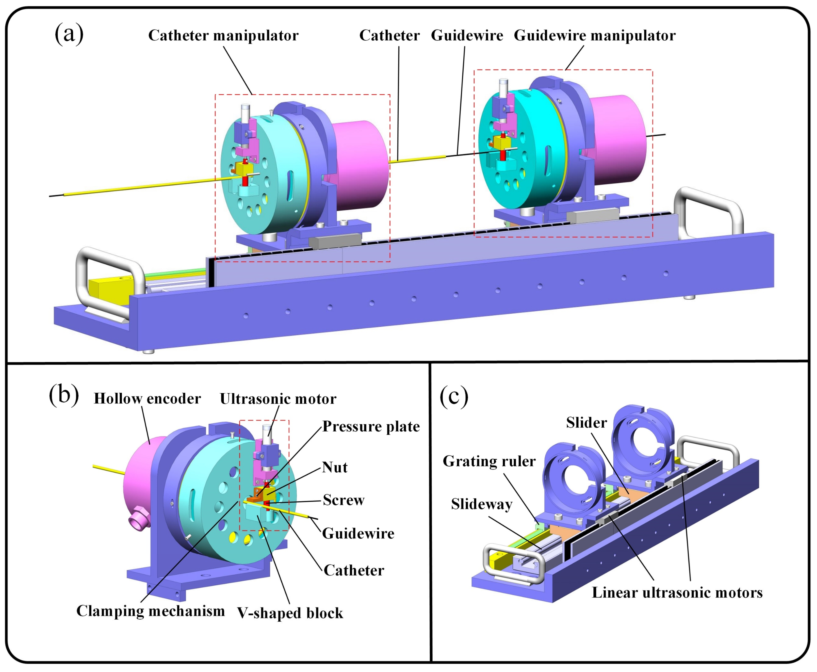
Figure 3.
Main components of the master robot.

Figure 4.
The explosion view (a) and section view (b) of the HUM. (c) The motion mechanism of the HUM.
Figure 4.
The explosion view (a) and section view (b) of the HUM. (c) The motion mechanism of the HUM.
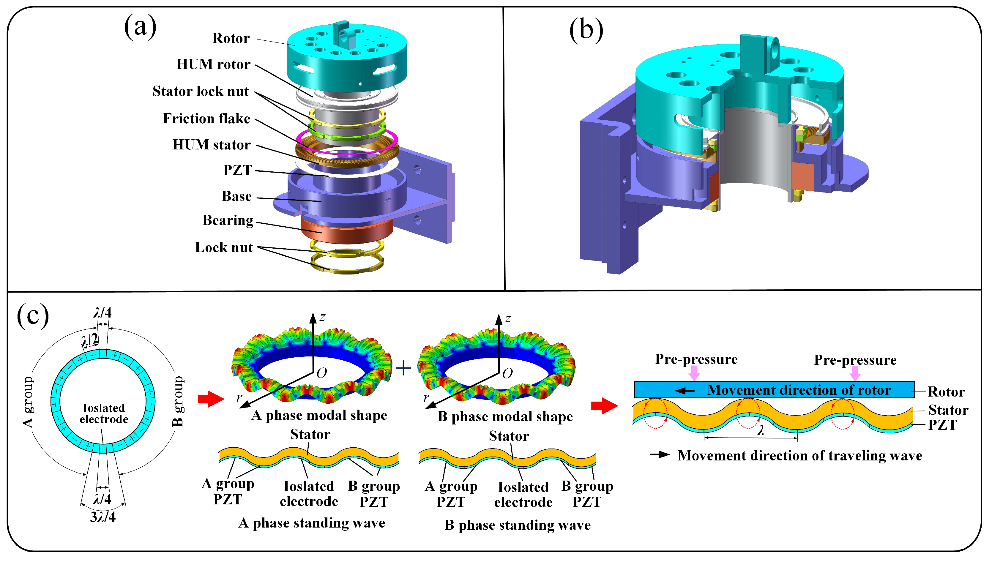
Figure 5.
Parametric structure of the HUM stator.
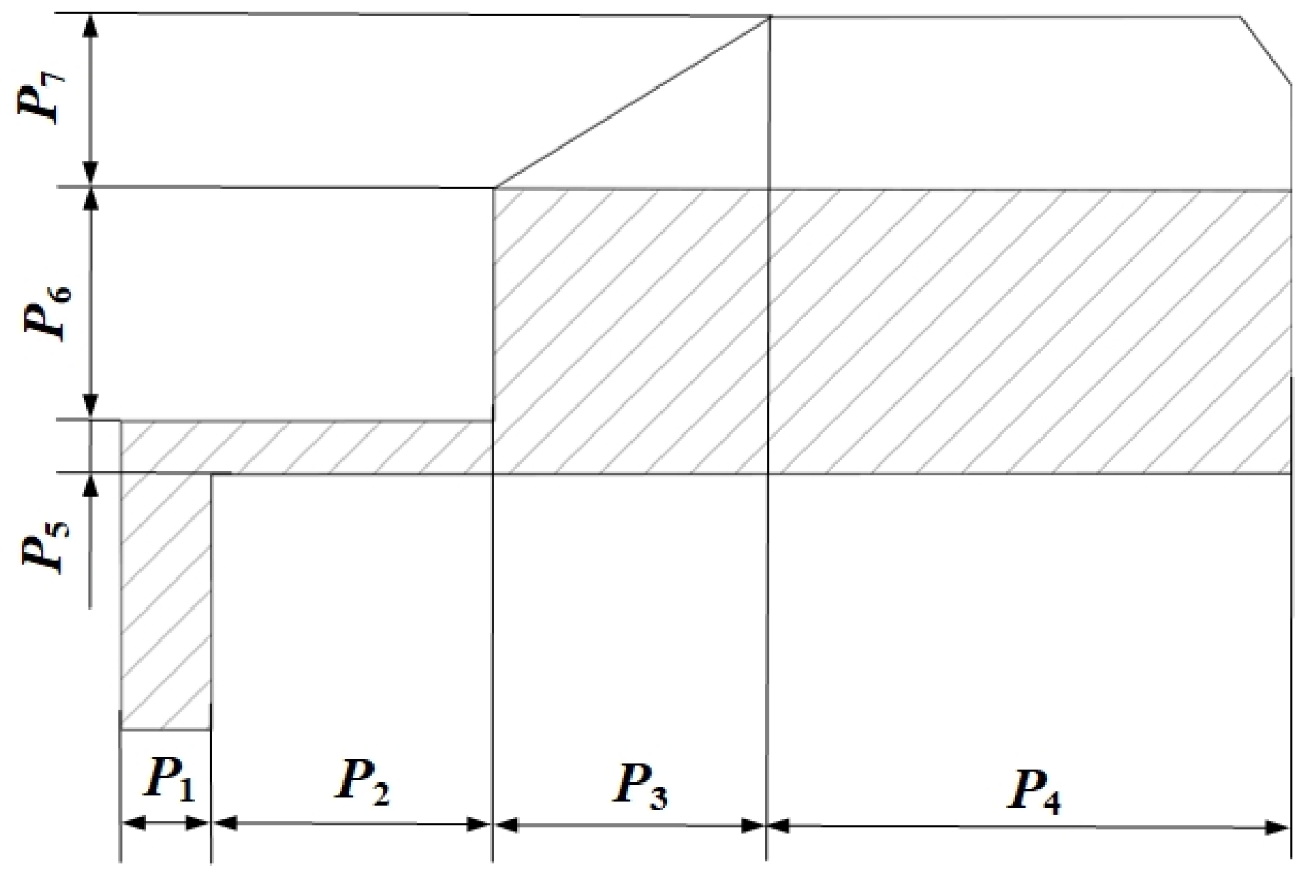
Figure 6.
The contribution rate of basis functions.
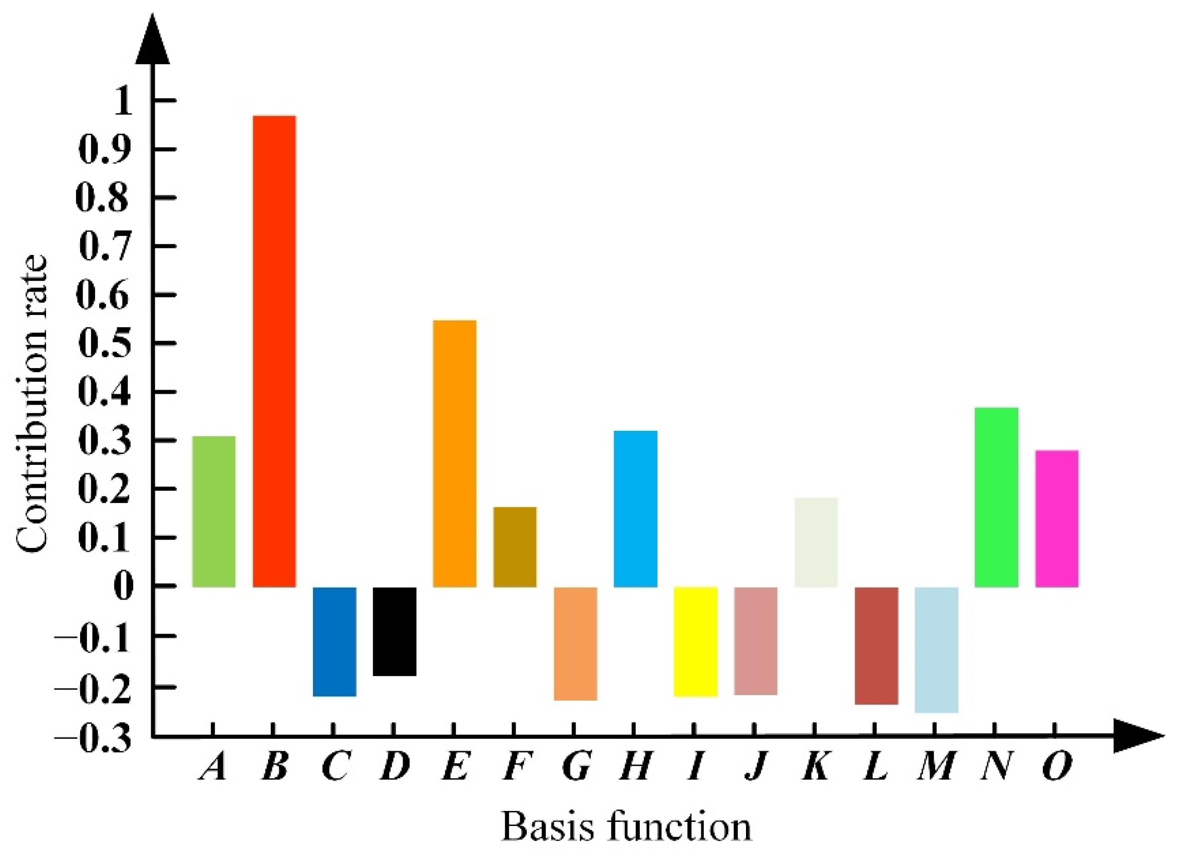
Figure 7.
Vibration test platform for the optimized stator of the HUM.
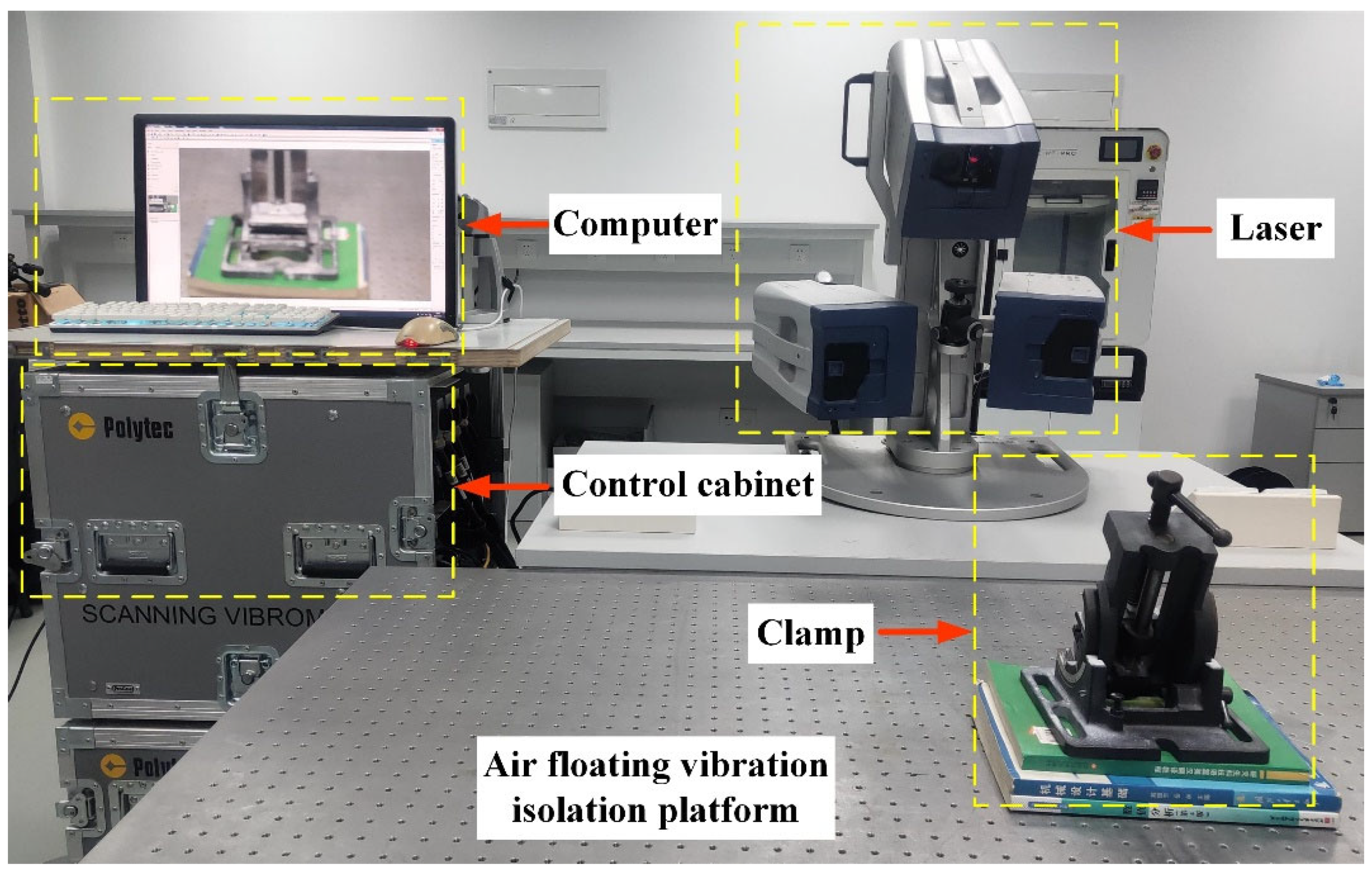
Figure 8.
Experimental platform for testing RVIR performance.
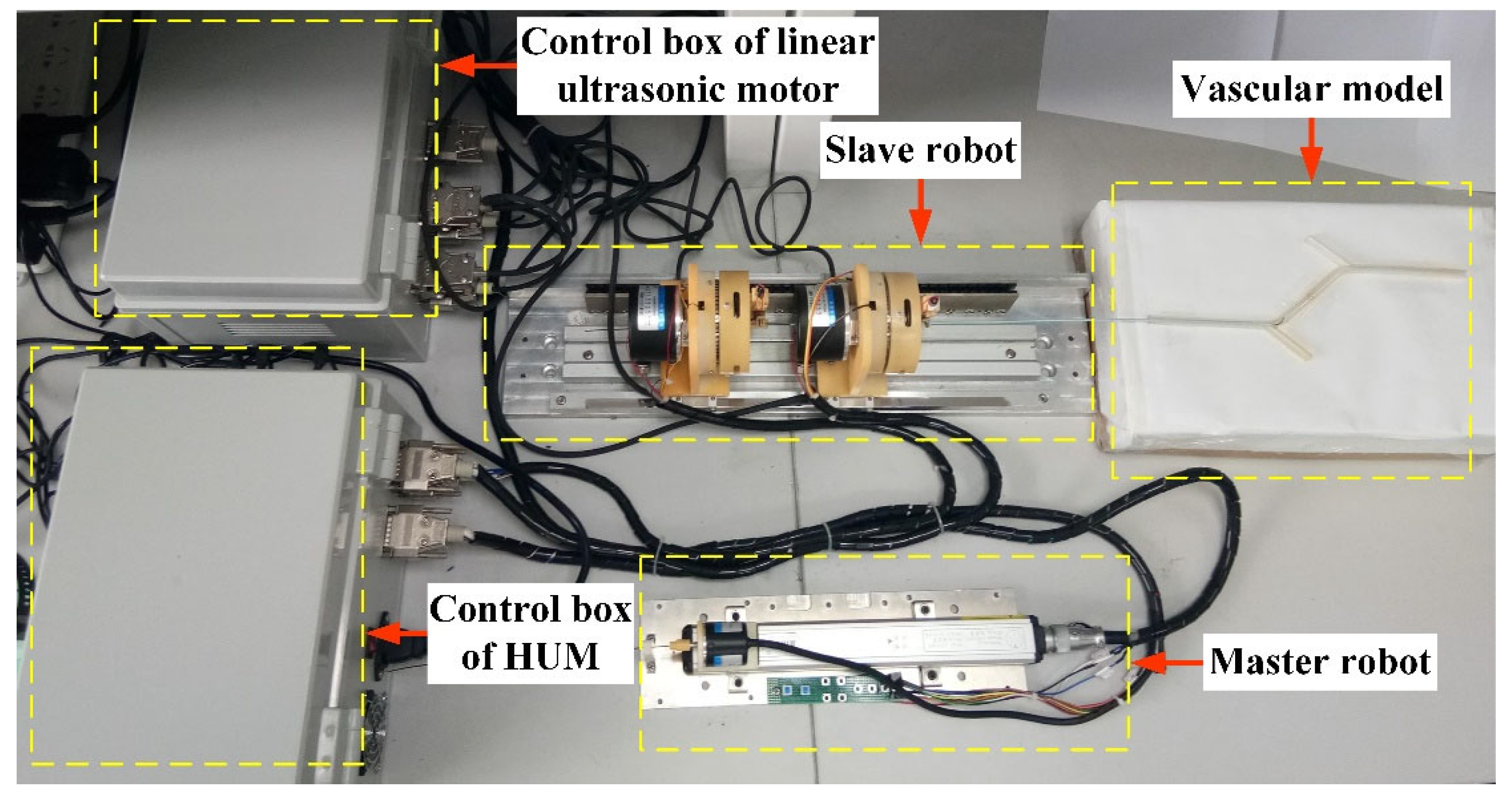
Figure 9.
Control schematic of rotary motion.
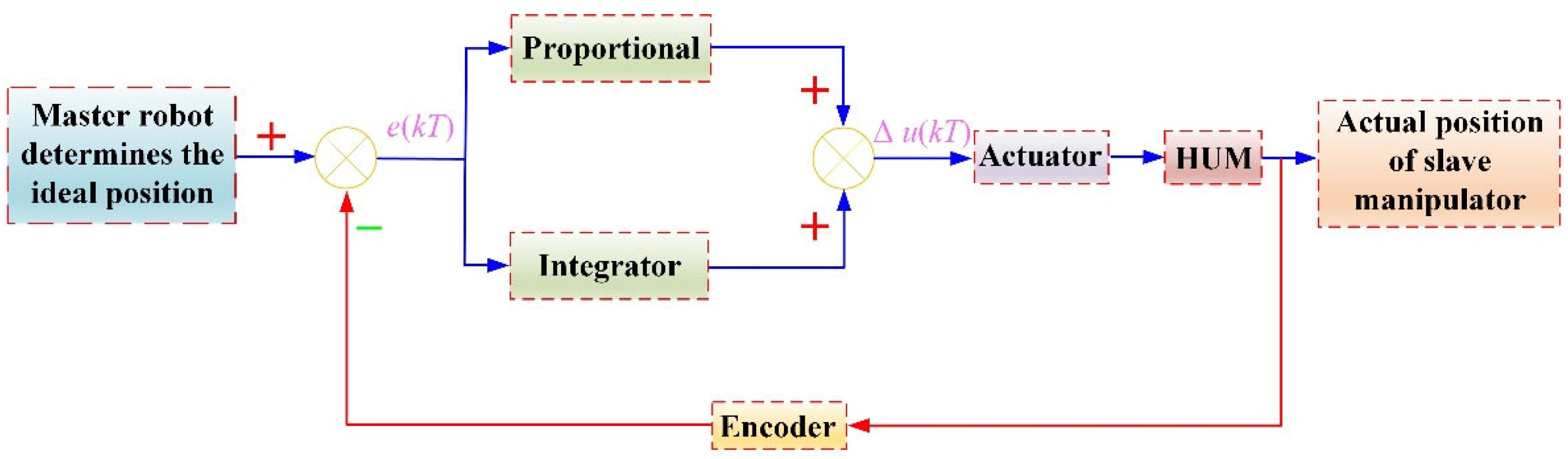
Figure 10.
Linear tracking trajectory, rotary tracking trajectory, and tracking errors of the GM (a,c,e) and CM (b,d,f).
Figure 10.
Linear tracking trajectory, rotary tracking trajectory, and tracking errors of the GM (a,c,e) and CM (b,d,f).

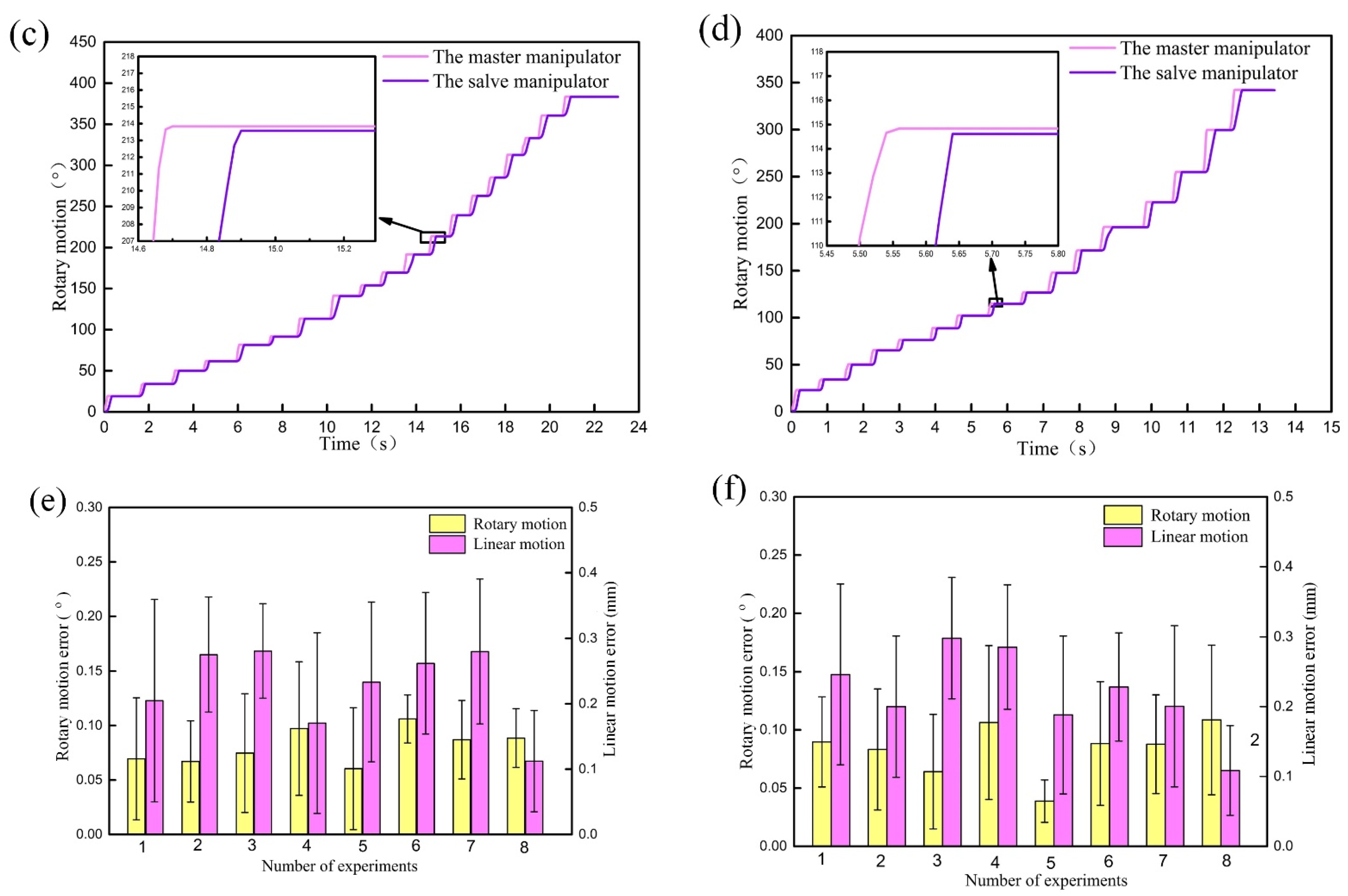
Figure 11.
Tracking trajectories and tracking errors of linear motion (a,b) and rotary motion (c,d) during cooperation.
Figure 11.
Tracking trajectories and tracking errors of linear motion (a,b) and rotary motion (c,d) during cooperation.

Figure 12.
The movement of guidewire and catheter (a–d). The linear displacement and rotary angle of the GM (e) and CM (f).
Figure 12.
The movement of guidewire and catheter (a–d). The linear displacement and rotary angle of the GM (e) and CM (f).


Table 1.
Optimization analysis process.
| Analysis Process | |
|---|---|
| Step 1 | Determine the optimal design space of the stator |
| Step 2 | Establish the optimization model of the stator |
| Step 3 | Use Latin hypercube sampling to obtain sample points |
| Step 4 | Calculate the response of the sample points |
| Step 5 | Filter data points |
| Step 6 | Build response surface model |
| Step 7 | Use a genetic algorithm to find the optimal solution in the whole domain |
Table 2.
Initial size and design space of the HUM stator.
| Design Variable | Initial Size/mm | Design Space/mm |
|---|---|---|
| P1 | 0.9 | 0.81–0.99 |
| P2 | 2.5 | 2.00–2.90 |
| P3 | 2.5 | 2.25–2.75 |
| P4 | 4.5 | 4.00–5.00 |
| P5 | 0.5 | 0.42–0.58 |
| P6 | 1.5 | 1.30–1.70 |
| P7 | 1.5 | 1.35–1.65 |
Table 3.
Comparison of experimental and FEA results.
| Frequency/kHz | Amplitude/μm | Stress/Mpa | |||||
|---|---|---|---|---|---|---|---|
| Ff | Fb | FA | FB | W0 | σin | ||
| FEA | Initial | 37.25 | 39.05 | 38.62 | 38.62 | 0.81 | 15.23 |
| Optimized | 36.52 | 40.64 | 38.43 | 38.43 | 2.79 | 11.17 | |
| TEST | Initial | 37.11 | 39.01 | 38.55 | 38.55 | 0.93 | — |
| Optimized | 36.37 | 40.53 | 38.43 | 38.43 | 3.12 | — | |
Table 4.
Slave robot driving accuracy test results.
| Object | Motion | Mean | SD | Cumulation |
|---|---|---|---|---|
| GM | Linear/mm | 0.12 | 0.035 | 0.57 |
| Rotary/° | 0.08 | 0.027 | 0.35 | |
| CM | Linear/mm | 0.13 | 0.029 | 0.45 |
| Rotary/° | 0.11 | 0.023 | 0.27 |
Publisher’s Note: MDPI stays neutral with regard to jurisdictional claims in published maps and institutional affiliations. |
© 2022 by the authors. Licensee MDPI, Basel, Switzerland. This article is an open access article distributed under the terms and conditions of the Creative Commons Attribution (CC BY) license (https://creativecommons.org/licenses/by/4.0/).
Share and Cite
MDPI and ACS Style
Lu, Q.; Sun, Z.; Zhang, J.; Zhang, J.; Zheng, J.; Qian, F. A Novel Remote-Controlled Vascular Interventional Robotic System Based on Hollow Ultrasonic Motor. Micromachines 2022, 13, 410. https://doi.org/10.3390/mi13030410
AMA Style
Lu Q, Sun Z, Zhang J, Zhang J, Zheng J, Qian F. A Novel Remote-Controlled Vascular Interventional Robotic System Based on Hollow Ultrasonic Motor. Micromachines. 2022; 13(3):410. https://doi.org/10.3390/mi13030410
Chicago/Turabian StyleLu, Qing, Zhijun Sun, Jialiang Zhang, Jiacheng Zhang, Juju Zheng, and Feng Qian. 2022. "A Novel Remote-Controlled Vascular Interventional Robotic System Based on Hollow Ultrasonic Motor" Micromachines 13, no. 3: 410. https://doi.org/10.3390/mi13030410
Note that from the first issue of 2016, this journal uses article numbers instead of page numbers. See further details here.