
Impact of Through-Hole Defects on the Electro-Explosive Properties of Exploding Foil Transducers
by

Kexuan Wang
1,
Jiangxu Wang
2,3,
Xinyu Li
2,
Dangjuan Li
2,
Junxia Cheng
2,
Jia Wang
2 and
Shenjiang Wu
2,* 1
Shaanxi Applied Physics and Chemistry Research Institute, Xi’an 710061, China
2
School of Optoelectronic Engineering, Xi’an Technological University, Xi’an 710021, China
3
Xi’an North Qinghua Electromechanical Co., Ltd., Xi’an 710025, China
*
Author to whom correspondence should be addressed.
Micromachines 2023, 14(8), 1499; https://doi.org/10.3390/mi14081499
Submission received: 7 July 2023
/
Revised: 23 July 2023
/
Accepted: 25 July 2023
/
Published: 26 July 2023
(This article belongs to the Special Issue Structural Analyses and Designs for Flexible/Stretchable Electronics, Volume II)
Abstract
:This study examines the impact of surface defects on the electro-explosive properties of metal explosive foil transducers. Specifically, it focuses on the effects of defects in the bridge foil and their influence on the electrical explosion time and transduction efficiency. To analyze these effects, a current-voltage simulation model is developed to simulate the behavior of a defective bridge foil. The simulation results are validated through experimental current-voltage measurements at both ends of the bridge area. The findings reveal that the presence of through-hole defects on the surface of the bridge foil leads to an advancement in the electrical explosion time and a reduction in the transduction efficiency of the bridge foil. A performance comparison is made between the defective bridge foil and a defect-free copper foil. As observed, a through-hole defect with a radius of 20 μm results in a 1 ns advance in the blast time and a 1.52% decrease in energy conversion efficiency. Similarly, a through-hole defect with a radius of 50 μm causes a 51 ns advancement in the blast time and a 13.96% reduction in the energy conversion efficiency. These findings underscore the detrimental effects of surface defects on the electro-explosive properties, emphasizing the importance of minimizing defects to enhance their performance.
1. Introduction
Pyrotechnics are ignition devices that utilize control information to convert initial energy into detonation energy [1]. They are capable of conducting and amplifying combustion or explosion energy in a specific manner to achieve work, detonation, and ignition. Among the various types of pyrotechnics, the exploding foil initiator (EFI), also known as the impact piece detonator, was initially developed by Stroud et al. at Moore National Laboratory, Lawrence Livermore National Laboratory (LLNL), USA [2]. Due to its high reliability, safety, high detonation rate, and resistance to interference [3], the EFI has gained increasing usage in engineering applications.
The transducer is a crucial component of the EFI system as it converts electrical energy into energy that is required for explosion. The structure, size, materials, and other factors of the transducer influence the energy utilization of the explosive foil detonation system, plasma generation, flying sheet speed, and other parameters [4,5,6]. Consequently, the electrical explosion performance of the bridge foil transducer is an important area of research both domestically and internationally. In the process of pyrotechnic detonation, the metal bridge foil and explosive column of the transducer are not in direct contact. The bridge foil undergoes electrical explosion only when subjected to a specific pulse of high current, thereby driving the shearing of the flying piece to achieve ignition or detonation [7].
Magnetron sputtering and photolithography are commonly employed processes for fabricating blast foil transducer elements [8,9,10]. During the fabrication of metal bridge foils, various defects of different shapes and depths such as blind holes, through-holes, and scratches can arise on the surface of the exploded foil transducer element due to factors such as holes, pits, burrs, foreign particulate matter, and target droplets on the substrate surface [11,12,13,14,15]. Eliminating film defects entirely is challenging [16], and even when films are deposited using HiPIMS, an advanced physical deposition method, a significant number of defects can still occur [17]. The generation of such defects can significantly impact the detonation time and transduction efficiency of explosive foil transducer elements.
Currently, there are limited theoretical studies focusing on the surface defects of bridge foils and their influence on the electrical explosive performance of exploding foil transducer elements. Most studies primarily rely on experimental methods [18]. In this study, through-hole defects are used as an example to investigate the effect of bridge defects on the electrical explosive performance of copper foil transducer elements through a combination of theoretical simulations and experimental methods. The theoretical simulations involve establishing a finite element analysis software-based model for calculating the temperature and current-voltage characteristics of the bridge foil with through-hole defects. The explosion time and energy utilization of three types of copper foils (defect-free, 20 μm radius through-hole defects, and 50 μm radius through-hole defects) are computed. Alumina ceramics are employed as the substrate to prepare defect-free copper foils, 20 μm radius through-hole defects, and 50 μm radius through-hole defects by magnetron sputtering and photolithography, respectively. The impact of through-hole defects on the electrical explosion performance of the bridge foil is analyzed by measuring the electrical explosion current and voltage curves using Rogowski coils and high-voltage probes.
2. Theories and Numerical Simulations
2.1. Bridge Foil Electro-Thermal Conversion Theory
This study utilizes COMSOL (https://cn.comsol.com/) multi-physics field finite element analysis software to conduct electro-thermal analysis of metal copper bridge foil. The analysis assumes that all electrical energy is converted into heat during the electrical explosion process and that the volume of the metal phase change remains constant. Furthermore, the physical properties, such as electrical conductivity and specific heat capacity, are assumed to vary with temperature, while the thermal conductivity of each material is considered constant. The heat source intensity within the domain Ω, Qe (x, y, z, t), is defined as the electrical loss. According to Joule’s law [19], Qe can be expressed as follows:
where J is the current density and E is the electric field strength. According to the law of conservation of charge, a current continuity equation holds within domain Ω:
where ρ is the space charge number density, and I is the capacitor short-circuit discharge current within the blast circuit.
From Equation (2), the current density in the bridge foil can be determined by calculating the current value in the exploded circuit. This calculation considers Faraday’s law [19] and Maxwell–Ampere’s law [19], allowing the expression of the current density J and the electric field strength E as follows:
where σ is the temperature-dependent conductivity in S/m, and φ is the potential in V. Substituting Equation (3) into Equation (1), the heat source intensity of the electrically generated heat of the bridge foil can be obtained as follows:
According to the heat calculation formula, the temperature is related to the heat source by the following equation:
Extracting the temperature information, it can be obtained that:
Equation (6) reveals that by acquiring the conductivity of the copper material, the density of the copper material, and the constant-pressure heat capacity of copper, calculating the current density of the electrical explosion using the current value from the short-circuit capacitance is feasible. This calculation enables the determination of the surface temperature of the bridge foil.
2.2. Bridge Foil Electro-Thermal Conversion Simulations
The structure and size of the bridge foil determine the ignition performance of the transducer element. The larger the central area of the bridge foil, the more energy is required for ignition, which will increase the difficulty of ignition. On the contrary, if the central area is too small, the manufacturing process is complex for production. In this study, a 1:1 3D model of the copper foil transducer element is employed [20,21,22,23]. The central area of the bridge foil is designed to have dimensions of 0.3 mm × 0.3 mm, an angle of 45°, and a thickness of 4 μm.
The modeling results are shown in Figure 1a. To facilitate the meshing of small through-hole structures, a triangular grid is utilized for the central area of the bridge foil. The through-hole is positioned at the origin of the coordinates, and geometric models of through-hole defective bridge foils and defect-free bridge foils with radii of 20 and 50 μm are established, as illustrated in Figure 1b–d, respectively.
The initiation system for copper foil is generally considered to be an RLC series circuit, as shown in Figure 2. The initial value for numerical simulation is the discharge current of the capacitor in the explosive circuit. In the electric explosion experiment, the initial step involves charging the capacitor using a power supply. Once the voltage of the capacitor aligns with the power supply voltage, it can be considered that the capacitor charging is complete. After receiving the detonation command, the detonation system initiates the closure of the high-voltage switch, triggering the discharge of the capacitor and resulting in the formation of a pulse current. This pulse current is responsible for inducing the electrical explosion of the copper foil [24]. In Figure 2, L1 and R1 are the self inductance and resistance of the circuit, respectively. The copper foil bridge can be successfully initiated when the charging voltage is 1100 V with a capacitance of 0.22 µF [22]. Therefore, an initial voltage of 1100 V and a capacitance of 0.22 µF were applied in the following simulations and experiments, resulting in a short-circuit current passing through the bridge foil from left to right.
The temperature distributions of the bridge area at 200 ns after energizing the bridges with different radius through-hole defects are computed by COMSOL, and the results are presented in Figure 3. These results indicate that through-hole defects in the bridge foil cause the electrical explosion temperature to be concentrated at the defect site. Moreover, the temperature is lower on the left and right sides of the through-hole defect, whereas it is higher on the top and bottom sides.
To further analyze the temperature variations, the average temperature within the central area (0.3 mm × 0.3 mm) of the bridge foil was calculated for the three copper foil transducer elements, and the results are displayed in Figure 4.
The findings demonstrate that the presence of through-hole defects leads to a higher temperature in the bridge foil compared with the defect-free bridge foil. This temperature increase is primarily due to the higher temperatures observed on the top and bottom sides of the through-hole defects. This is due to the reason that, when the current flows through the foil bridge from left to right, the current flow around the through-hole will be disturbed, the current density along the tangent direction of the current flow (the top and bottom sides of the through-hole) is much higher than that along the current flow direction (the left and right sides of the through-hole), resulting in higher temperatures on the top and bottom sides of the through-hole defects. Consequently, the average temperature in the bridge area rises significantly faster in the presence of through-hole defects compared with that in the case of the defect-free bridge foil.
2.3. Calculations of Bridge Foil Current and Voltage
According to Kirchhoff’s law [19], the equation for the detonation circuit current is:
For a charging capacitor, the following relationship holds:
Substituting Equation (8) into Equation (7), the differential equation for the current can be obtained as follows:
Solving Equation (9) yields the expression for the variation of current with time as follows:
where U0 refers to the detonation circuit voltage, C0 the detonation circuit charging capacitance, L the detonation circuit parasitic inductance value, R0 the charging circuit resistance value, and R(t) the bridge foil explosion process resistance value. Equation (10) expresses the current in the detonation circuit in terms of R0, L, R(t), C0, and U0 to determine the current. The conductivity of the bridge foil can be calculated by the conductivity formula [25]:
where is the conductivity of the bridge foil when the temperature is , is the variation coefficient of conductivity with temperature, is the electron density (cm−3), is the atomic density (cm−3), z is the ion equivalent charge, with the metal volume expansion coefficient and metal isobaric specific heat capacity , e is the electron charge, is the electron energy relaxation time, is the electron mass, is the chemical potential of metal, k is the Boltzmann constant, and can be calculated by the Fermi–Dirac integral.
Substituting the temperature results calculated in Section 2.2 into Equation (11), the bridge foil resistance R(t) can be calculated from the following equation:
where l and are the length and cross-section area of the bridge foil, respectively.
The above relationships lead to the construction of the following system of equations:
Equation (13) was solved using the fourth-order Longacurta algorithm to obtain the explosion process current y3 of the exploding foil. The calculated electrical explosion current–voltage curves for bridge foils with various sizes of through-hole defects are presented in Figure 5.
2.4. Analysis of Simulation Results
The electrical explosion time of the copper foil is defined as the peak point of the voltage curve. By analyzing the voltage curves, the electrical explosion times of copper foils with different sizes of through-hole defects are determined, as depicted in Figure 6.
The energy transfer efficiency is a crucial parameter for assessing the electrical explosive performance of the bridge foil. It is defined as the ratio of the energy stored in the bridge foil to the stored capacitive energy of the detonation circuit:
where u and i are the voltage and current during the electroburst of the copper foil, respectively, C is the value of the energy storage capacitance, U0 is the initial detonation circuit charging voltage, and t0 is the effective energy deposition time.
In the EFI ignition system, the flying sheet acceleration process typically takes approximately 200 ns [22]. Therefore, a time node of 200 ns after the electrical explosion point of the bridge foil can be used to distinguish the effective energy deposition. Within this 200 ns period following the electrical explosion, it is considered as an effective energy deposition time. Any data beyond 200 ns after the electrical explosion are not included in the calculation of the effective energy deposition on the bridge foil. The simulation results listed in Table 1 indicate that through-hole defects have a significant impact on the electrical explosion time and conversion efficiency of copper foil transduction elements. Specifically, larger through-hole defects result in earlier electrical explosion times of the bridge foil and lower conversion efficiency.
3. Experiment and Results
In this study, three types of copper foil transducer elements were fabricated: (1) a defect-free copper foil, (2) a copper foil with a 20 μm radius through-hole defect, and (3) a copper foil with a 50 μm radius through-hole defect. First, copper film with the thickness of 4 μm was coated on alumina ceramic substrate by magnetron sputtering technique; then, the copper film was etched into the butterfly shaped bridge shown in Figure 1 by photolithography technique; the through-hole defects were artificially manufactured on the bridge by laser drilling technique.
To measure the current and voltage during the electrical explosion, the Rogowski coil method were utilized [22]. The experimental system for the electrical explosion test of the exploding foil includes a high-voltage pulse power supply, a Rogowski coil, a Digital high-voltage meter, and an oscilloscope, as illustrated in Figure 7.
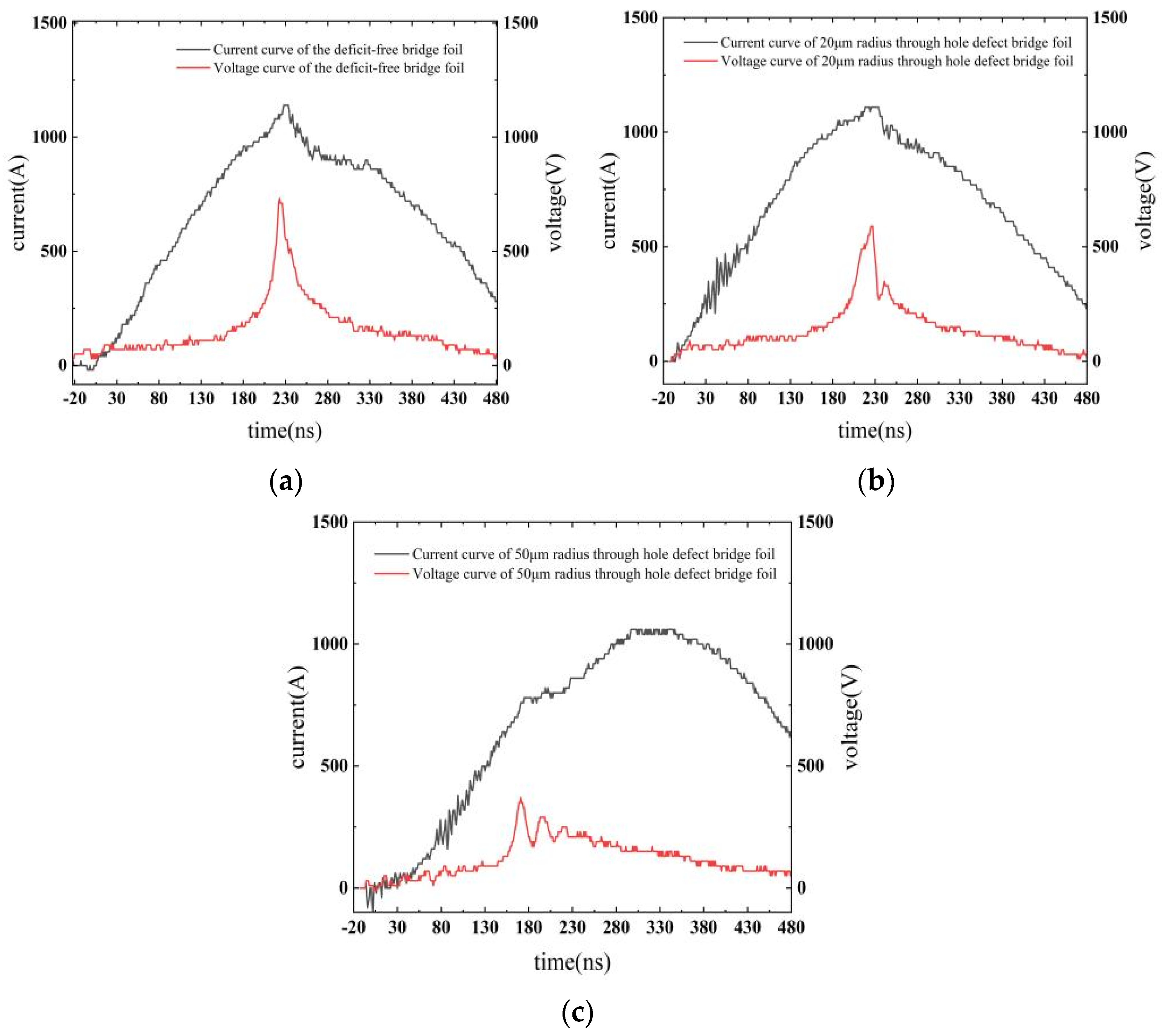
The high-voltage pulse power supply is an RLC series detonation circuit, as depicted in Figure 2, to ignite the bridge foils. The Rogowski coil is used to measure the current of the circuit, the digital high-voltage meter is used to measure the voltage of the circuit, and the oscilloscope is used to collect and display the current and voltage values measured by the Rogowski coil. The current and voltage curves obtained during the electrical explosion process of the three types of copper foil are presented in Figure 8.
The simulated calculations for the defect-free bridge foil, 20 μm radius through-hole defect bridge foil, and 50 μm radius through-hole defect bridge foil were compared with the experimentally measured explosion time, bridge foil deposition energy, and explosion current voltage. The comparison results are summarized in Table 2.
For the defect-free and 20 μm through-hole bridge foils, the experimental and calculated values are similar, with a minimum relative error of 0.44% and a maximum relative error of 3.44%; for the 50 μm through-hole bridge foil, the error between the experimental and calculated values increases with a maximum relative error of 12.06%. The results demonstrate suitable agreement of the simulation model with the experiment.
Compared with the defect-free bridge foil, when the through-hole defect radius is 20 μm, the bridge foil’s electrical explosion time is advanced by 1 ns, and the energy conversion efficiency is reduced by 1.52%. Similarly, when the through-hole defect radius is 50 μm, the bridge foil’s electrical explosion time is advanced by 51 ns, and the energy conversion efficiency is reduced by 13.96%.
4. Conclusions
In this study, the impact of through-hole defects on the electrical explosion time and transduction efficiency of bridge foils was investigated using a combination of finite element numerical simulations and experiments. The following three conclusions are drawn from the results:
- (1)
- Through-hole defects lead to an advancement in the explosion time, and the size of the through-hole determines the extent of this advancement. The relationship between the through-hole radius and the bridge foil explosion time follows a quadratic function.
- (2)
- Through-hole defects significantly reduce the transduction efficiency of the bridge foil transducer element during electrical explosion.
- (3)
- Specifically, when the through-hole radius is 20 μm, the through-hole defect causes the bridge foil explosion time to advance by 1 ns, and the energy conversion efficiency is reduced by 1.52%. When the through-hole radius increases to 50 μm, the through-hole defect leads to a 51 ns advancement in the bridge foil explosion time and a 13.96% reduction in the energy conversion efficiency. When the structure of the bridge area or the size of the through-hole changes, the values of the explosion time advance and the energy conversion definitely will vary; the specific values need to be further determined through simulations and experiments.
These findings highlight the critical role of through-hole defects in influencing the electrical explosion behavior and performance of bridge foils.
Author Contributions
Conceptualization, K.W.; investigation, D.L. and J.C.; methodology, K.W.; software, J.W. (Jiangxu Wang); validation, S.W.; writing—original draft, J.W. (Jia Wang); writing—review and editing, X.L. All authors have read and agreed to the published version of the manuscript.
Funding
This research was funded by National Defense Key Laboratory Fund, grant number WDYX21614260204, Shaanxi Provincial Science and Technology Department project, grant number 2022JQ-027.
Data Availability Statement
All data that support the findings of this study are included within the article.
Conflicts of Interest
The authors declare no conflict of interest.
References
- Smit, K.J.; Morgan, M.; Pietrobon, R. Pyrotechnic films based on thermites covered with PVC. Propellants Explos. Pyrotech. 2019, 44, 37–40. [Google Scholar] [CrossRef]
- Stroud, J.R. A New Kind of Detonator the Slapper; Lawrence Livermore National Lab: Livermore, CA, USA, 1976. [Google Scholar]
- Xu, C.; Zhu, P.; Zhang, W.; Shen, R.; Ye, Y. A plasma switch induced by electroexplosion of p-n junction for mini exploding foil initiator. IEEE Trans. Plasma Sci. 2019, 47, 2710–2716. [Google Scholar] [CrossRef]
- Zhang, Q.; Xu, C.; Zhu, P. Planar trigger switch and its integrated chip with exploding foil initiator based on low-temperature cofired ceramic. IEEE Trans. Power Electron. 2019, 35, 2908–2916. [Google Scholar] [CrossRef]
- Zhi, Y.; Peng, Z.; Qing, C. A micro-chip exploding foil initiator based on printed circuit board technology. Def. Technol. 2022, 18, 1435–1444. [Google Scholar]
- Sun, L.; Zhan, Z.; Wu, Z. Optimizing cure temperature of polyimide flyer for exploding foil initiator applications. J. Appl. Polym. Sci. 2022, 139, e53072. [Google Scholar]
- Wu, J.; Wang, L.; Li, Y.; Yang, L.; Sultan, M.; Chen, L. Characteristics of a plasma flow filed produced by a metal array bridge foil explosion. Plasma Sci. Technol. 2018, 20, 075501. [Google Scholar] [CrossRef] [Green Version]
- Wang, K.; Zhu, P.; Xu, C.; Zhang, Q.; Yang, Z.; Shen, R. Firing performance of microchip exploding foil initiator triggered by metal-oxide-semiconductor controlled thyristor. Micromachines 2020, 11, 550. [Google Scholar] [CrossRef] [PubMed]
- Hwang, H.J.; Kim, D.J.; Jang, Y.R.; Hwang, Y.T.; Jung, I.H.; Kim, H.S. Multi-pulsed flash light sintering of copper nanoparticle pastes on silicon wafer for highly-conductive copper electrodes in crystalline silicon solar cells. Appl. Surf. Sci. 2018, 462, 378–386. [Google Scholar] [CrossRef]
- Li, D.; Li, S.; Wang, K.; Cheng, J.; Wang, J.; Wu, S.; Su, J. Study of the explosive bridge film using laser shaping technology. Micromachines 2022, 13, 854. [Google Scholar] [CrossRef] [PubMed]
- Madhavi, G.; Kishan, N.; Raghavendra, C.R. A review on recent approaches in the field of surface coating. Mater. Today Proc. 2022, 52 Pt 3, 403–406. [Google Scholar] [CrossRef]
- Sanchez, N.; Neal, W.; Jensen, B. Dynamic initiator imaging at the advanced photon source: Understanding the early stages of initiator function and subsequent explosive interactions. In Proceedings of the 20th Biennial Conference of the APS Topical Group on Shock Compression of Condensed Matter, St. Louis, MO, USA, 9–14 July 2017; American Physical Society: College Park, MD, USA, 2017. [Google Scholar]
- Neal, W.; Bowden, M. High fidelity studies of exploding foil initiator bridges, Part 2: Experimental results. In AIP Conference Proceedings; AIP Publishing LLC: Melville, NY, USA, 2017; Volume 1793. [Google Scholar]
- Neal, W.; Garasi, C. High fidelity studies of exploding foil initiator bridges, Part 3: Alegra MHD simulations. In AIP Conference Proceedings; AIP Publishing LLC: Melville, NY, USA, 2017; Volume 1793. [Google Scholar]
- Neal, W.; Sanchez, N.; Jensen, B. The effect of surface heterogeneities in exploding metal foils. In AIP Conference Proceedings; AIP Publishing LLC: Melville, NY, USA, 2018; Volume 1979. [Google Scholar]
- Costa, M.Y.P.; Venditti, M.L.; Cioffi, M.O.H. Fatigue behavior of PVD coated Ti-6Al-4V alloy. Int. J. Fatigue 2011, 33, 759–765. [Google Scholar] [CrossRef] [Green Version]
- Panjan, P.; Čekada, M.; Panjan, M. Surface density of growth defects in different PVD hard coatings prepared by sputtering. Vacuum 2012, 86, 794–798. [Google Scholar] [CrossRef] [Green Version]
- Zhao, Y.; Zeng, Q.; Feng, C. Theoretical model for calculating electric-power curves depicting accelerated flyer by exploding foil. J. Beijing Inst. Technol. 2010, 19, 8–13. [Google Scholar]
- Guru, B.S.; Hiziroğlu, H.R. Electromagnetic Field Theory Fundamentals, 2nd ed.; Cambridge University Press: New York, NY, USA, 2004. [Google Scholar]
- Chu, E.; Liu, W.; Xue, Y.; Zhang, R. Study on parametrized structural design of micro-heater and its resistance calculation. Initiat. Pyrotech. 2017, 6, 1–5. [Google Scholar]
- Guo, F.; Fu, Q.; Wang, Y.; Wang, M.; Huang, H.; Shen, R. Effects of fabrication process on drive capability of flyer with copper bridge foil. Chin. J. Energetic Mater. 2015, 23, 787–790. [Google Scholar]
- Zhou, M.; Zhang, J.; Tong, H.; Qin, G.; Li, J.; Wang, Y. Study on the effect of copper foil thickness on detonation performance of explosive foil initiator. Initiat. Pyrotech. 2019, 4, 14–18. [Google Scholar]
- Li, D.; Zhang, W.; Li, S. Secondary ignition of carbon-based bridge coating triggered by low voltage. Mater. Res. Express 2021, 8, 045607. [Google Scholar]
- Ying, G.F.; Li, X.W.; Jia, S.L. Electrical characteristics of microsecond electrical explosion of Cu wires in air under various parameter. Trans. Plasma Sci. 2018, 46, 972–981. [Google Scholar]
- Lee, Y.T.; More, R.M. An electron conductivity model for dense plasma. Phys. Fluids 1984, 27, 1273–1286. [Google Scholar] [CrossRef]
Figure 1.
Modeling results of copper foil transducer: (a) Bridge foil meshing; (b) 50 μm radius through-hole bridge foil; (c) 20 μm radius through-hole bridge foil; and (d) defect-free bridge foil.
Figure 1.
Modeling results of copper foil transducer: (a) Bridge foil meshing; (b) 50 μm radius through-hole bridge foil; (c) 20 μm radius through-hole bridge foil; and (d) defect-free bridge foil.

Figure 2.
Initiation circuit for copper foil.

Figure 3.
Calculated temperature gradient distribution at 200 ns for three types of bridge foil. (a) 50 μm radius through-hole bridge foil; (b) 20 μm radius through-hole bridge foil; and (c) defect-free bridge foil.
Figure 3.
Calculated temperature gradient distribution at 200 ns for three types of bridge foil. (a) 50 μm radius through-hole bridge foil; (b) 20 μm radius through-hole bridge foil; and (c) defect-free bridge foil.
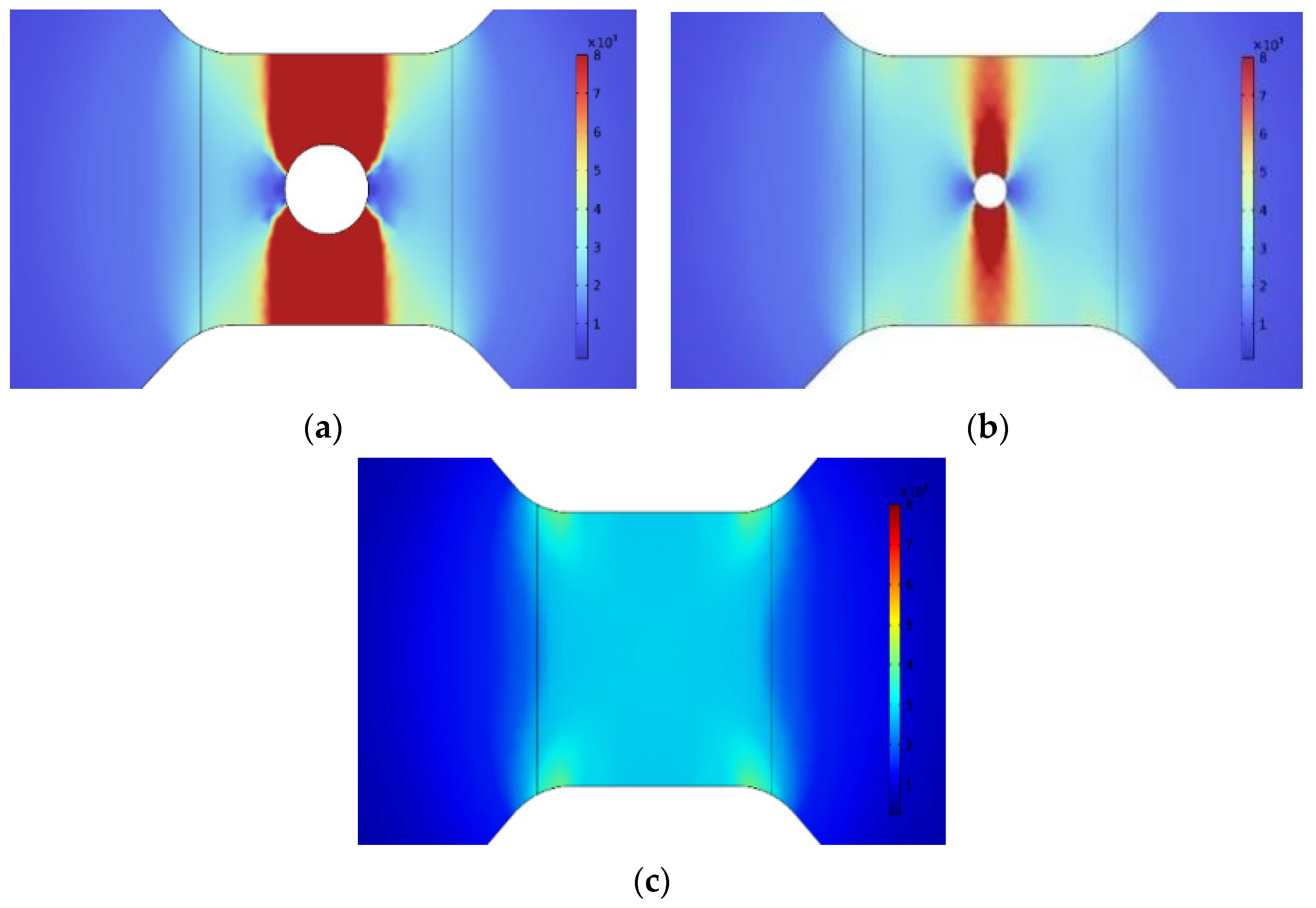
Figure 4.
Effect of through-hole defects on the average temperature in the bridge area of the copper foil.
Figure 4.
Effect of through-hole defects on the average temperature in the bridge area of the copper foil.
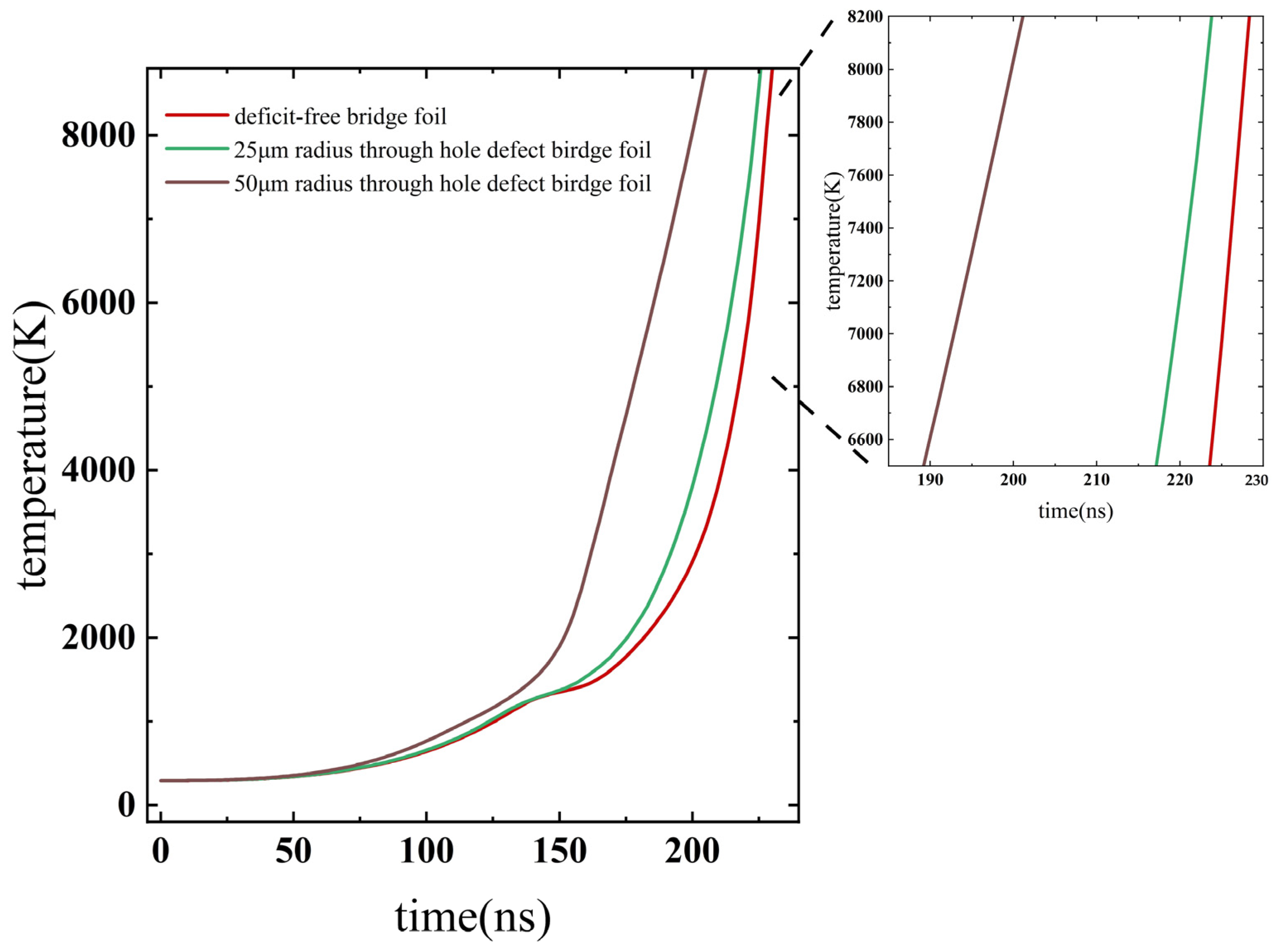
Figure 5.
Copper foil electrical explosion current–voltage curve.

Figure 6.
Electrical explosion time for copper foils with different defect sizes.

Figure 7.
Experiment setup for ignition.
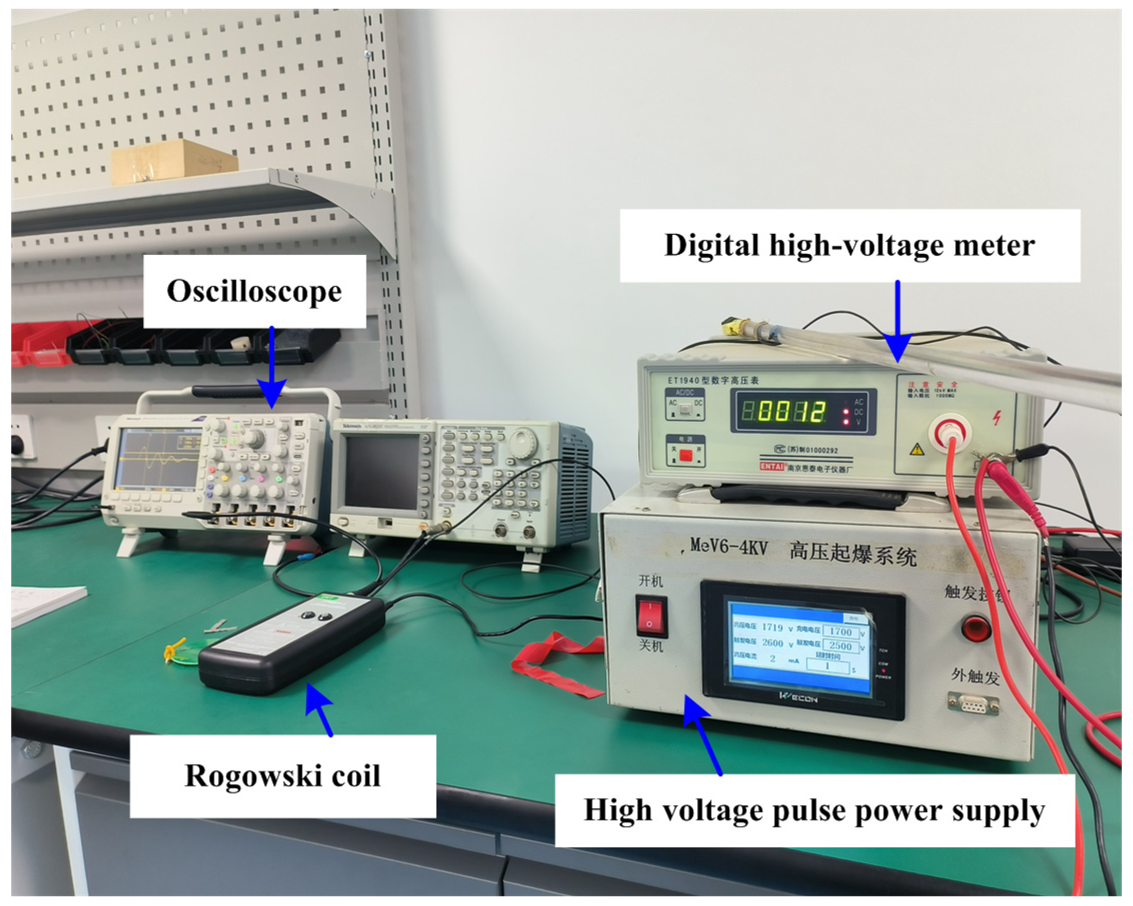
Figure 8.
Experimentally measured current-voltage curves for the three bridge foils. (a) Defect-free bridge foil current-voltage curve; (b) Bridge foil current-voltage curve for a 25 μm radius through-hole defect; (c) Bridge foil current-voltage curve for a 50 μm radius through-hole defect.
Figure 8.
Experimentally measured current-voltage curves for the three bridge foils. (a) Defect-free bridge foil current-voltage curve; (b) Bridge foil current-voltage curve for a 25 μm radius through-hole defect; (c) Bridge foil current-voltage curve for a 50 μm radius through-hole defect.

Table 1.
Parameters of electro-explosive properties.
| Defect Size | Explosion Time/ns | Deposited Energy/mJ | Capacitive Energy Storage/mJ |
|---|---|---|---|
| Defect-free bridge foil | 227 | 62.86 | 133.10 |
| 20 μm radius through-hole defect | 223 | 62.26 | 133.10 |
| 50 μm radius through-hole defect | 199 | 49.39 | 133.10 |
Table 2.
Comparisons of the electro-explosive parameters by calculation and experiment.
| Defect Size | Parameters | Experimental Values | Calculated Values | Relative Errors |
|---|---|---|---|---|
| defect-free bridge foil | Outbreak time/ns | 226 | 227 | 0.44% |
| Deposited energy/mJ | 62.15 | 62.86 | 1.13% | |
| Energy conversion efficiency | 46.69% | 47.23% | 1.14% | |
| 20 μm through-hole bridge foil | Outbreak time/ns | 225 | 223 | −0.90% |
| Deposited energy/mJ | 60.12 | 62.26 | 3.43% | |
| Energy conversion efficiency | 45.17% | 46.78% | 3.44% | |
| 50 μm through-hole bridge foil | Outbreak time/ns | 175 | 199 | 12.06% |
| Deposited energy/mJ | 43.56 | 49.39 | 11.80% | |
| Energy conversion efficiency | 32.73% | 37.11% | 11.80% |
Disclaimer/Publisher’s Note: The statements, opinions and data contained in all publications are solely those of the individual author(s) and contributor(s) and not of MDPI and/or the editor(s). MDPI and/or the editor(s) disclaim responsibility for any injury to people or property resulting from any ideas, methods, instructions or products referred to in the content. |
© 2023 by the authors. Licensee MDPI, Basel, Switzerland. This article is an open access article distributed under the terms and conditions of the Creative Commons Attribution (CC BY) license (https://creativecommons.org/licenses/by/4.0/).
Share and Cite
MDPI and ACS Style
Wang, K.; Wang, J.; Li, X.; Li, D.; Cheng, J.; Wang, J.; Wu, S. Impact of Through-Hole Defects on the Electro-Explosive Properties of Exploding Foil Transducers. Micromachines 2023, 14, 1499. https://doi.org/10.3390/mi14081499
AMA Style
Wang K, Wang J, Li X, Li D, Cheng J, Wang J, Wu S. Impact of Through-Hole Defects on the Electro-Explosive Properties of Exploding Foil Transducers. Micromachines. 2023; 14(8):1499. https://doi.org/10.3390/mi14081499
Chicago/Turabian StyleWang, Kexuan, Jiangxu Wang, Xinyu Li, Dangjuan Li, Junxia Cheng, Jia Wang, and Shenjiang Wu. 2023. "Impact of Through-Hole Defects on the Electro-Explosive Properties of Exploding Foil Transducers" Micromachines 14, no. 8: 1499. https://doi.org/10.3390/mi14081499
Note that from the first issue of 2016, this journal uses article numbers instead of page numbers. See further details here.