1. Introduction
Tactile sensors deploying many capacitive force sensing elements on a flexible polymer substrate, e.g., polydimethylsiloxane (PDMS), have been researched to make them conform to the 3-D surface of robotic fingers, artificial limbs,
etc. [
1,
2]. These sensors have a problem in that metallic electrodes formed on the polymer are possibly broken when it is subjected to large stress, especially when it is directly contacted with an object. One of the causes of breakage is that the adhesion of metal to polymer is essentially not very strong. Another cause is that mechanical properties such as Young’s modulus are different between these materials,
i.e., electrodes and flexible substrate. If the stress generated by an applied force is larger than the adhesion strength, the electrodes would break.
There is another problem. If the gap length between two facing electrodes is increased to widen the sensing range, the sensitivity of the capacitance is degraded. Employing a feedback control system to regulate the gap length at the same value is one possible solution [
3], however, it is complicated and expensive.
Our force sensing device solves these problems. The device is fabricated using a Parylene on liquid deposition (PoLD) technique, in which polymer thin films are chemically deposited directly onto nonvolatile liquids under low-pressure conditions [
4].
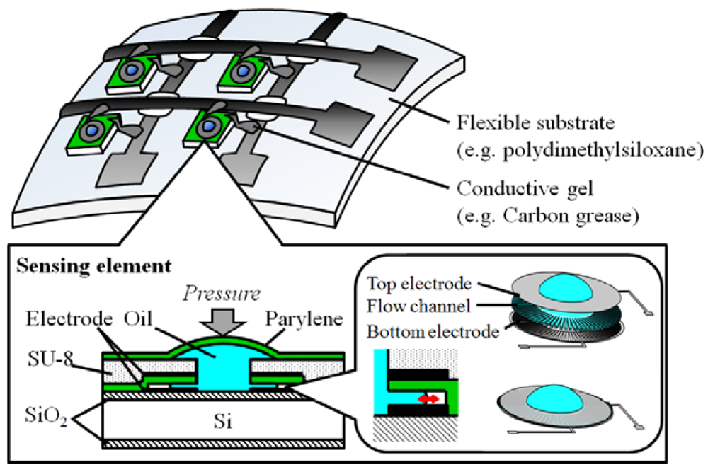
Figure 1 shows the arrayed sensing elements on a flexible substrate, where stretchable electrodes such as conductive carbon grease [
5,
6] would be usable for electrically connecting sensing elements. Since the channel has no directly applied external force, the electrodes do not suffer from damage problems. Appropriate sensitivity and sensing range can be designed independently by adjusting the cross-section and the length of the channel, respectively. In this paper, the first trial device of a force sensing element was fabricated on a silicon wafer in order to demonstrate our principle.
Figure 1.
Schematic of flexible tactile sensor.
Figure 1.
Schematic of flexible tactile sensor.
2. Theory
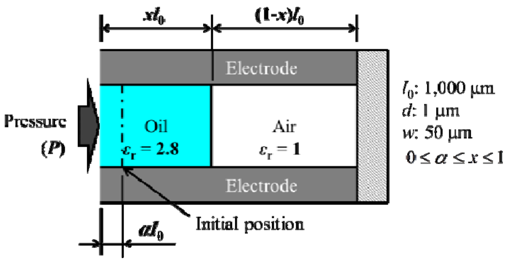
Figure 2 shows the simplified model of flow inside the channel. When the force (
F) is applied on the dome shape, the pressure (
Px) is expressed as follows:
where A, P0 are the area of receiving force, and the atmospheric pressure, respectively. Assume the initial ratio of oil in the channel is α, then the Px is calculated based on Boyle’s law as follows:
where x is the ratio of oil in the channel after the force is applied. Substituting Equation (1) into Equation (2), the F is obtained as follows:
The capacitance (C) between electrodes is as follows:
where ε0, εr are the dielectric constants of vacuum and oil, w, l0, d are the width, length, and height of channel. By measuring C, F is obtained according to Equations (3) and (4).
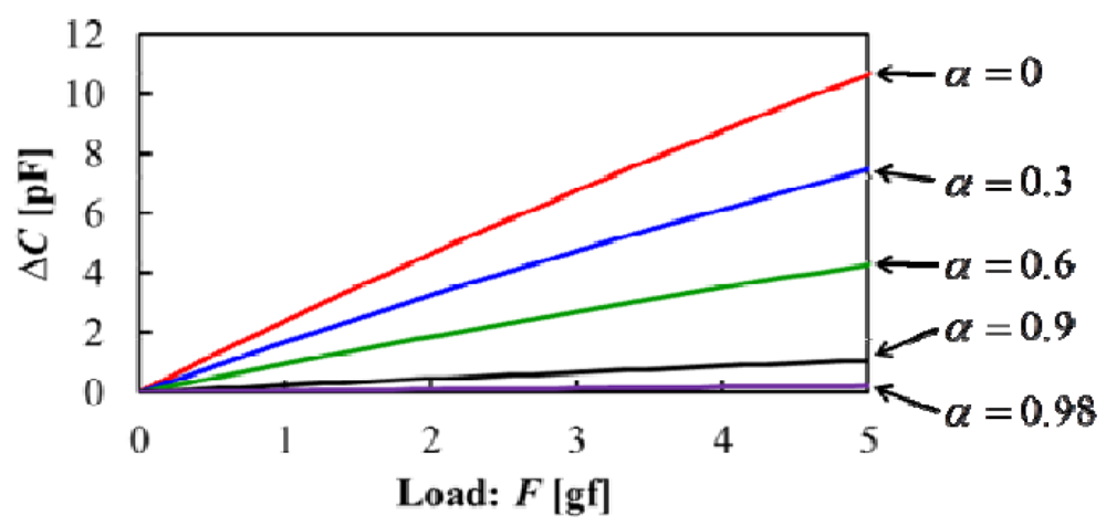
Figure 3 shows an example of a calculated result of the relationship between the load and the change in capacitance by changing the initial ratio
α. The values of
w,
l0,
d are 1,000 μm, 50 μm, 1 μm, respectively. Looking at this figure, it is proven that the higher sensitivity can be realized when the parameter
α is initially set as the smaller value.
Figure 2.
Simplified model of tactile sensor.
Figure 2.
Simplified model of tactile sensor.
Figure 3.
Load vs. change in capacitance dependent on initial position (α).
Figure 3.
Load vs. change in capacitance dependent on initial position (α).
3. FEM Simulation
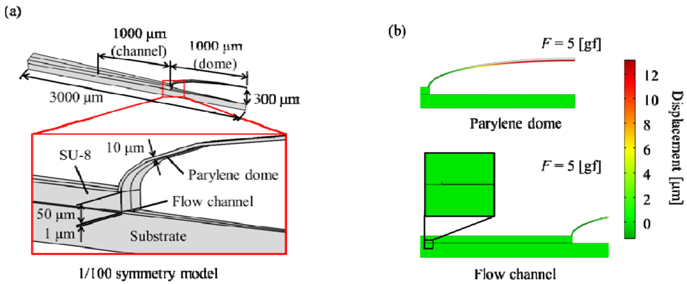
In our device, the channel structure is currently made with SU-8 polymer. Based on the design of the SU-8 structure, the displacement of channel height with respect to the applied force was simulated by a finite element method (FEM). The liquid was not included in this simulation. It is anticipated that the displacement of the dome and the flow channel with liquid becomes lower than that without liquid, so the simulation results include errors compared to the real device. As FEM software, COMSOL Multiphysics® by COMSOL, Inc. was used.
The signal noise of this sensor depends on unwanted displacement of the channel height, which is due to the structural deformation of the channel caused by that of the dome. When the force is applied on the dome, the pressure is generated on the surface of the flow channel, which is the same as that on the area receiving the force.
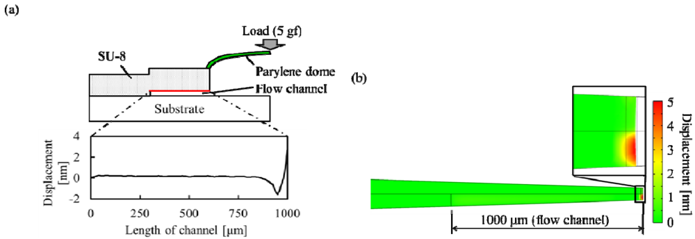
Figure 4 shows the simulation model and results. The sensor is symmetrical in terms of the rotational direction, so the section model in the radial direction was employed. The length, width, and height of flow channel are 1,000 μm, 50 μm, and 1 μm, respectively. The thickness and height of the Parylene dome are 10 μm and 300 μm, respectively. The height of the SU-8 structure is 50 μm.
Figure 4.
(a) Finite element method (FEM) simulation model; (b) Displacement of Parylene dome and flow channel.
Figure 4.
(a) Finite element method (FEM) simulation model; (b) Displacement of Parylene dome and flow channel.
When the applied force is 5 gf, the maximum displacement of the Parylene dome is 13 μm.
Figure 5 shows the displacement in the z-direction of the flow channel, maximum and average, which are 2.4 nm, and 0.3 nm, respectively. These values are very small. The simulation result shows that the unwanted
z-displacement of the flow channel due to the load applied on the dome shape is sufficiently negligible for the oil position measurement inside the channel in the
x-direction.
Figure 5.
(a) Displacement of flow channel line. (b) Displacement of flow channel plane.
Figure 5.
(a) Displacement of flow channel line. (b) Displacement of flow channel plane.
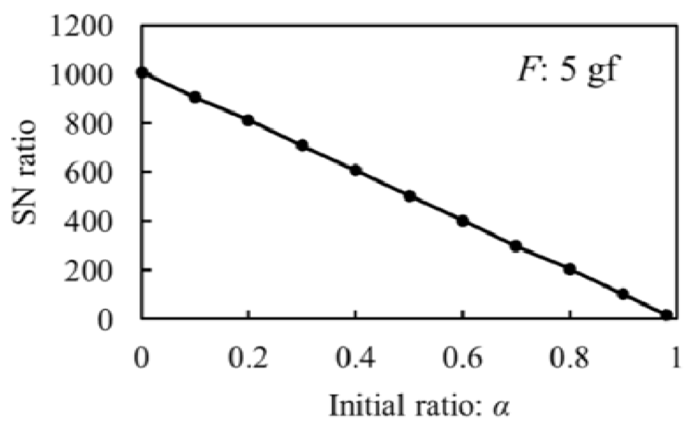
Figure 6 shows the relationship between initial ratio (
α) (see
Figure 2 and
Section 1) and SN ratio at 5 gf applied force. The SN ratio is defined as follows:
where, ∆Cchannel and ∆Coil are the change in capacitances by displacement of channel height in the z-direction and the displacement of oil in the channel in the x-direction (calculated using Equation (4)), respectively. SN ratio is 18 when α is 0.98. SU-8 structure is sufficient to sense signal change in capacitance.
Figure 6.
Initial ratio vs. SN ratio at load weight of 5 gf.
Figure 6.
Initial ratio vs. SN ratio at load weight of 5 gf.
4. Design and Fabrication
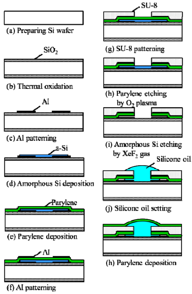
Figure 7 shows the fabrication process for the first trial device of the force sensing element. The bottom aluminum electrode is formed on a thermally oxidized Si wafer (
Figure 7(a-c)). The thickness of aluminum and SiO
2 are 0.3 μm and 1 μm, respectively. After forming the bottom electrodes, amorphous silicon (a-Si) as a sacrificial layer is deposited. The thickness of a-Si is 1 μm, which is equal to the height of the flow channel (
Figure 7(d)). Parylene is deposited as a flexible insulating layer, which reliably prevents the two facing electrodes from discharge. The thickness of Parylene is 1 μm. After forming the top aluminum electrode, SU-8 is spin-coated and patterned as the device structure (
Figure 7(f,g)). Parylene is etched away using O
2 plasma (
Figure 7(h)). For making the flow channel, a-Si is etched away using XeF
2 gas (
Figure 7(i)). After dropping silicone oil (Shin-Etsu Chemical, Hivac F-4, kinematic viscosity: 37 cSt) using a dropping pipette manually, it is then covered by a Parylene film (
Figure 7(j,h)). The packaging of the oil by a Parylene film is based on a PoLD technique already described in the
Section 1.
Figure 7.
Fabrication process of forced senor.
Figure 7.
Fabrication process of forced senor.
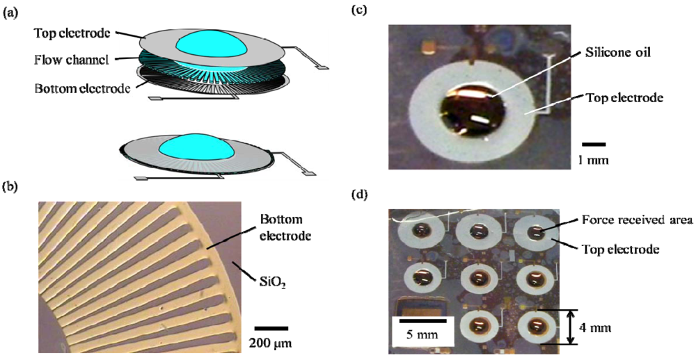
Figure 8 shows the fabrication results. The bottom electrode shape is radial (
Figure 8(a,b)). The number of flow channels is 100. The diameter of the single sensing element is 4 mm (
Figure 8(c)). The initial position of oil in the channel cannot be seen because the top aluminum electrode masks the whole of the channel. The arrayed sensing elements are fabricated on a Si wafer (
Figure 8(d)). The fabrication of the arrayed device on a flexible substrate is ongoing work.
Figure 8.
(a) Schematic of force received area. (b) Photograph of radial-shaped bottom electrode. (c) Photograph of one sensing element, of which diameter is 4 mm. (d) Photograph ofarrayed sensing elements which as yet have not been fabricated on a flexible substrate.
Figure 8.
(a) Schematic of force received area. (b) Photograph of radial-shaped bottom electrode. (c) Photograph of one sensing element, of which diameter is 4 mm. (d) Photograph ofarrayed sensing elements which as yet have not been fabricated on a flexible substrate.
5. Evaluation
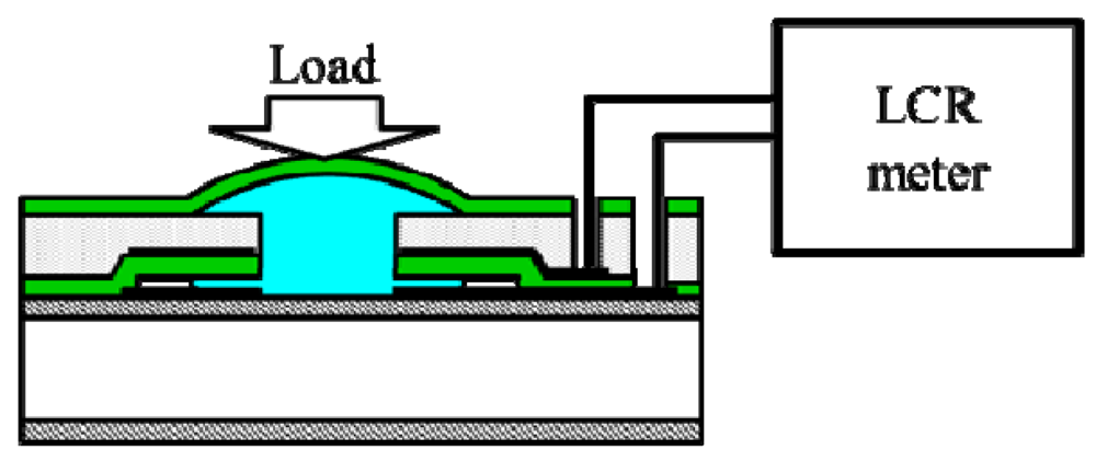
Figure 9 shows the schematic of the measurement setup of the fabricated sensing elements. The change in capacitance is measured by a LCR meter (Agilent Technology Inc., E4980A, accuracy is 0.05%). The probes were contacted on the electrodes. The weight was applied on the Parylene dome using commonly used tweezers. The weight is made of paper, because a stray capacitance occurs in the case of using a metal weight.
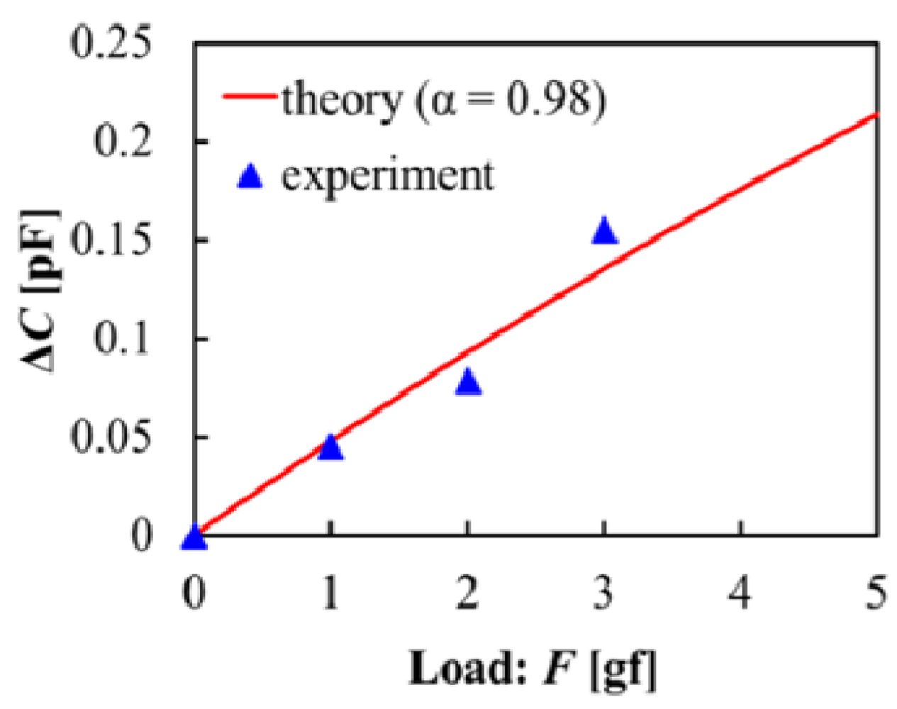
Figure 10 shows the relationship between load weight (
F) and change in capacitance (Δ
C), which shows the basic potential of the device for detecting force. A sensitivity of 0.05 pF/gf is achieved.
Figure 9.
Schematic of measurement setup.
Figure 9.
Schematic of measurement setup.
Figure 10.
Change in capacitance vs. adding force.
Figure 10.
Change in capacitance vs. adding force.
The experimental sensitivity was the same as the theoretical one in the case of α is 0.98. It indicates that the initial ratio of oil in the channel was supposedly 0.98, i.e., the movable range of oil was 20 μm. These values cannot be measured because of the above mentioned problem of invisibility. The reason for large α may be that the air is degassed inside the channel while Parylene is deposited at low pressure. Controlling α to an arbitrary value is rather difficult in the present state as the oil is packaged by Parylene film.
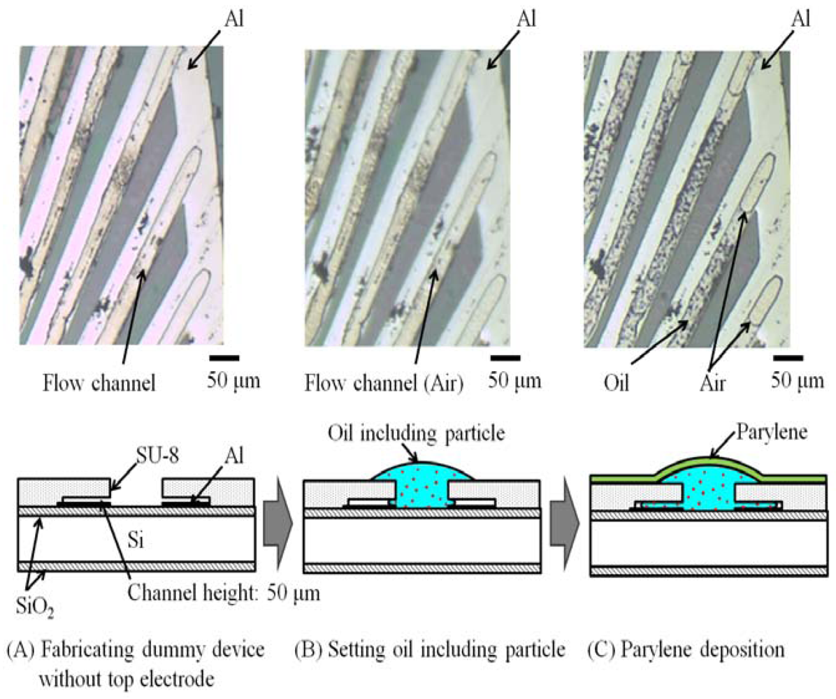
How the oil flows into the channel is observed using a dummy device without a top electrode. The flow inside this device is visible with an optical microscope. The channel height of the device was 50 μm. Using this device, it is possible to measure the oil position (x-coordinate) in response to the applied load on the domed shape.
Figure 11.
Oil position at packaging process stage.
Figure 11.
Oil position at packaging process stage.
Figure 11 shows the transition of the oil position during the packaging process. The oil part can be recognized, since it contains particles. After setting the oil, the oil did not feed into the channels at all (
Figure 11(B)), which means that the capillary attraction is negligible when the channel height is 50 μm. After deposition of Parylene, the oil was fed into the channel and the length of the air part became 90 μm (
α = 0.94) (
Figure 11(C)), which means that the degassing effect due to low pressure in the Parylene deposition process is dominant in defining the
α parameter in this case. As mentioned in the theory section, lower
α leads to higher sensitivity. Lowering
α by contriving a fabrication process, e.g., packaging the oil at atmospheric pressure, is ongoing work.
6. Conclusions
We propose a flexible capacitive force sensor with nonbreakable electrodes with regard to the applied force. The displacement of the channel height with respect to the applied force is simulated by FEM, showing that the SU-8 structure is sufficient to sense the change in capacitance with a high S/N ratio.
The first trial device of the force sensing element has been fabricated. A sensitivity of 0.05 pF/gf was achieved. The experimental sensitivity was the same as the theoretical one when
α is 0.98, because the air was degassed during Parylene deposition. In future work, we aim to fabricate the sensor with higher air concentration inside the channel by packaging of the oil at atmospheric pressure, since low
α is effective in increasing the sensitivity. In future work, the sensing elements should be fabricated on a flexible substrate. The conceptual schematic has been shown in
Figure 1 in the
Section 1. The sensing elements on a silicon wafer are diced. The dies are glued to a flexible substrate such as PDMS. The metal electrodes of several tens of micrometers in thickness are patterned on the flexible PDMS substrate. Carbon grease wirings connect the sensing elements and electrodes onto the flexible substrate. The sensing array is fixed on a curved surface and the change in capacitance when force is applied is measured.
Acknowledgments
This work was supported in part by JSPS (Japan Society for the Promotion of Science) KAKENHI (22310083). This work was sported in part by the Kansai University Special Research Fund, 2010. This work was supported in part by a grant of “Strategic Research Foundation Grant-aided Project for Private Universities”: Matching Fund Subsidy MEXT (Ministry of Education, Culture, Sport, Science, and Technology, Japan), 2010-2014 (S1001048). This work was carried out in part by the High Technology Research Center (HRC).
References
- Lee, H.-K.; Chung, J.; Chang, S.-I.; Yoon, E. Normal and shear force measurement using a flexible polymer tactile sensor with embedded multiple capacitors. IEEE J. Microelectromech. Syst. 2008, 17, 934–942. [Google Scholar] [CrossRef]
- Someya, T.; Sekitani, T.; Iba, S.; Kato, Y.; Kawaguchi, H.; Sakurai, T. A large-area, flexible pressure sensor matrix with organic field-effect transistors for artificial skin applications. Proc. Natl. Acad. Sci. USA 2004, 101, 9966–9970. [Google Scholar]
- Suzuki, S.; Tuchitani, S.; Sato, K.; Yokota, Y.; Sato, M.; Esashi, M. Semiconductor capacitance-type accelerometer with PWM electrostatic servo technique. Sens. Actuat. A: Phys. 1990, 21–23, 316–319. [Google Scholar]
- Binh-Khiem, N.; Matsumoto, K.; Shimoyama, I. Polymer thin film deposited on liquid for varifocal encapsulated liquid lenses. Appl. Phys. Lett. 2008, 93, 124101:1–124101:3. [Google Scholar]
- Petralia, M.T.; Wood, R.J. Fabrication and Analysis of Dielectric-elastomer Minimum-Energy Structures for Highly-deformable Soft Robotic Systems. In Proceedings of the IEEE/RSJ Conference on Intelligent Robots Systems (IROS2010), Taipei, Taiwan, 18–22 October 2010; pp. 2357–2363.
- Maleki, T.; Chitnis, G.; Ziaie, B. A batch-fabricated laser-micromachined PDMS actuator with stamped carbon grease electrodes. J. Micromech. Microeng. 2011, 21. [Google Scholar]
© 2012 by the authors; licensee MDPI, Basel, Switzerland. This article is an open-access article distributed under the terms and conditions of the Creative Commons Attribution license (http://creativecommons.org/licenses/by/3.0/).


