Article

Deployable and Conformal Planar Micro-Devices: Design and Model Validation

Mechanical and Aerospace Engineering Department, University of California, Los Angeles, CA 90095, USA
*
Author to whom correspondence should be addressed.
Micromachines 2014, 5(3), 528-546; https://doi.org/10.3390/mi5030528
Submission received: 19 December 2013 / Revised: 22 July 2014 / Accepted: 31 July 2014 / Published: 11 August 2014

Abstract

:
We report a design concept for a deployable planar microdevice and the modeling and experimental validation of its mechanical behavior. The device consists of foldable membranes that are suspended between flexible stems and actuated by push-pull wires. Such a deployable device can be introduced into a region of interest in its compact “collapsed” state and then deployed to conformally cover a large two-dimensional surface area for minimally invasive biomedical operations and other engineering applications. We develop and experimentally validate theoretical models based on the energy minimization approach to examine the conformality and figures of merit of the device. The experimental results obtained using model contact surfaces agree well with the prediction and quantitatively highlight the importance of the membrane bending modulus in controlling surface conformality. The present study establishes an early foundation for the mechanical design of this and related deployable planar microdevice concepts.

1. Introduction

Deployable devices that can be introduced into a region of interest in their compact collapsed states and then deployed to cover large volumes or surface areas are of great interest to various engineering and biomedical applications [1,2,3,4,5]. These include deployable sensor networks for structural health monitoring or robotics applications, compact launch-volume structures for space applications and stents/catheters/optoelectrode arrays for minimally invasive diagnosis and treatments of cardiovascular and neuronal diseases.
Existing deployable devices and tools, in particular those employed for minimally invasive bio-medical procedures, are mostly limited to mechanical functionalities. They also target limited geometries, as they very often rely on inflatable balloons for deployment [6,7]. Adapting these device designs for planar configurations while at the same time providing the ability to incorporate electrical, optoelectronic and other sensing and actuation capabilities are highly desirable to further expand the usage of deployable devices and to facilitate the exploration of novel applications.
A conceptual design of our deployable planar device is shown in Figure 1. Foldable thin-film membranes, which may incorporate 2D electrode arrays or other electronic or optical components, as demonstrated in many recent studies on flexible electronics [8], are suspended between semi-flexible stems via embedded wire guides. The device may be introduced through a small burr hole in its compact collapsed state (the membranes fully folded). The push-pull wires then allow the membranes to be deployed in situ along a gap and cover a large surface area.
The membranes must be sufficiently flexible to conformally contact typical engineering surfaces or tissues that contain topographical features. Previous studies reported mechanical modeling of the behavior of flexible conformal membranes. Kim et al. [9] predicted the tensile and compressive strains of epidermal electrodes that may be conformally attached to human skin. Other studies examined the deformation of thin membranes under elastocapillary effects. An analytic model reported in [10], for example, describes the folding and reopening processes of capillary-driven origami structures. In this and related models, the behavior of thin membranes subjected to capillary forces are studied by considering the mutual interaction between the surface and elastic energies [11,12,13].
We extend these past efforts and develop analytic models to investigate the conformality of flexible membranes as they contact surfaces and experimentally validate the models. We note that our goal for this analytic modeling is to help establish a basic understanding of the mechanics involved using simplified test cases rather than to examine complex geometric situations of a specific application.
Figure 1. (a) Conceptual design of the deployable planar device. The foldable membranes, which may incorporate thin film electrode arrays, are suspended between stems via push-pull wires. These electrode arrays may, for example, be used for electrocorticography (ECoG) monitoring of cortical surfaces. (b) Zoomed view of the device in its collapsed and deployed state.
Micromachines 05 00528 g001

2. Mechanical Models

To help quantify the conformality of the membranes, which is a key feature of our device concept, we define the bending angle θ1 as the angle between the membrane and the push-pull control wire (Figure 2). Our basic approach is to find this bending angle by identifying a minimum energy state of the membrane in contact with a model surface for different combinations of the extent of device deployment (as quantified by the deployment factor) and the surface topographic parameter (as quantified by the sulcus radius of curvature). The membrane bending radii and functional figures of merit, such as the membrane coverage and utilization ratios, can then be calculated based on the bending angle thus determined.
We consider a single membrane fold, which is approximated as linearly interconnected segments, each with a uniform radius of curvature. The total energy Et of the fold is the sum of its elastic strain energy Ee and the interfacial energy Es (in contact with a surface via an interfacial fluid): Et = Ee + Es. The equilibrium bending angle is considered the one that minimizes Et under a given geometric constraint.
The elastic strain energy per unit area e of a membrane segment that is bent to a radius of curvature R can be written as e = B/2R2. Here, B = Eh3/[12 (1 − ν2)] is the bending modulus of the membrane, E is the Young’s modulus, ν is the Poisson’s ratio and h is the thickness of the membrane [14,15,16]. The present analytic model considers only a 2D deformation of the membrane, and all of the energy terms are considered per unit width (into the page) of the membrane. The total elastic strain energy Ee can be obtained as the sum of the strain energies of all of the segments:
E e = i = 1 n e i A i
where Ai is the area of the membrane segment with a radius of curvature Ri.
The surface/interfacial energy Es can be generally expressed as Es = γsgAsg + γlgAlg + γslAsl, where γ’s are the surface tension coefficients and A’s are the corresponding areas of solid-gas, liquid-gas and solid-liquid interfaces. We consider two simplified topographies of contact surfaces for analytic modeling in the present study: (1) a featureless flat surface; and (2) a flat surface incorporating a sulcus (or valley). The latter may be considered to be emulating surfaces of internal organs (for example, gyri on cortical surfaces and digestive tracks).
As mentioned before, the bending angle is determined to be the one that minimizes the total system energy under a given set of conditions. We first identify a range of possible bending angles, with the loose maximum being simply 180°. There exists a lower bound to the bending angle, θmin, due to the geometric constraints imposed by the push-pull wire and the holes punctured in the membrane. This is also the “initial” bending angle that the membrane may assume under a given deployment condition before making contact with a surface. The θmin is obtained by searching the minimum elastic energy state under given geometric constraints.

2.1. Featureless Flat Surface

Based on our experimental observation, we approximately represent a single fold of the membrane using seven segments: one flat segment of length l2, two sets of two bent segments with radii of curvature, R1 and R2, respectively, and two unbent segments of length l1 (Figure 2).
Figure 2. Geometric model of the membrane in contact with a featureless flat surface. (a) Top view of the membrane in a released state; (b) side view; (c) optical image of the membrane in its side view.
Micromachines 05 00528 g002
These geometric parameters of the membrane are inter-related:
2l1 + 2R1θ1 + l2 = l
2l1 cosθ1 + 2R1 sinθ1 + 2R2 sinθ1 + l2 = d
2R2θ1 = s
As illustrated in Figure 2a,b, l is the total length of a single fold of the polyimide membrane, s is the spacing between two adjacent holes for the push-pull wire and d is the deployment distance.
The parameters l and s are fixed for a given device design, but d is adjustable (increased from d0 at the initial collapsed state) during a deployment process.
The total energy is next expressed as a function of the bending angle θ1. After algebraic manipulation, we write:
E t = B ( θ 1 R 1 + 2 θ 1 2 s ) + γ sg l ( γ sg + γ 1g γ s1 ) l 2 + γ 1g d
where:
l 2 = l θ 1 cos θ 1 d θ 1 + s sin θ 1 2 R 1 θ 1 ( θ 1 cos θ 1 sin θ 1 ) θ 1 ( cos θ 1 1 )
Note that, in practice, the bending angle is always non-zero and greater than θmin after the device is deployed. Therefore, we do not consider a trivial case of θ1 = 0° in the model.

2.2. Flat Surface Incorporating a Sulcus

We next consider a flat surface with a sulcus illustrated in Figure 3. The sulcus is located in the middle of the flat surface and modeled using two circular arcs of radius Rs. The membrane is assumed to bend with a constant radius of curvature R3 over the sulcus. A second bending angle θ2 is used to quantify the ability of the membrane to conformally follow the contour of the sulcus.
Figure 3. (a) Geometric model of the membrane in contact with a featureless flat surface in side view; (b) optical image of the membrane in its side view.
Micromachines 05 00528 g003
Similar to our model for the featureless flat substrate, we first relate the geometric parameters of the bent membrane:
2l1 + 2R1θ1 + l2 + 2(R3 + Rs)θ2 = l
2l1 cosθ1 + 2R1 sinθ1 + 2R2 sinθ1 + l2 + 2Rs = d
(R3 + Rs) sinθ2 = Rs
2R2θ1 = s
Once again, s is the spacing between adjacent holes for the push-pull wire and R2 is the radius of the bent segment between these holes (Figure 2).
The total energy of the membrane is then written as:
E t = B ( θ 1 R 1 + 2 θ 1 2 s + θ 2 R 3 + θ 2 R s ) + γ sg l ( γ sg + γ 1g γ s1 ) ( l 2 + 2 R s θ 2 ) + γ 1g d
where:
l 2 = ( l θ 1 cos θ 1 sin θ 2 d θ 1 sin θ 2 + s sin θ 1 sin θ 2 ) 2 R 1 θ 1 sin θ 2 ( θ 1 cos θ 1 sin θ 1 ) 2 R s θ 1 ( θ 2 cos θ 1 sin θ 1 ) θ 1 ( cos θ 1 1 ) sin θ 2

2.3. Non-Dimensionalization

To help gain further physical insights and “generalize” our models, we recast the equations for identifying the minimum energy states in their dimensionless forms. We define an elastocapillary length [17] LEC as LEC = (B/γ)1/2 where B is once again the bending modulus of the membrane B = Eh3/[12 (1 − ν2)] and γγsg + γlgγsl. A membrane longer than this characteristic length will be significantly deflected by the surface tension force.
Using the featureless flat surface as an example, we write the first order derivatives of the total energy in their dimensional form and set them equal to zero:
E t θ 1 = B ( 1 R 1 + 4 θ 1 s ) ( γ sg + γ 1g γ s1 ) l 2 θ 1 = 0
E t R 1 = B ( θ 1 R 1 2 ) ( γ sg + γ 1g γ s1 ) l 2 R 1 = 0
After non-dimensionalizing all of the geometric parameters (R1, s, l, d) using LEC and rearranging the terms, we obtain:
1 R ˜ 1 + 4 θ 1 s ˜ + sin θ 1 ( cos θ 1 1 ) 2 [ 2 R ˜ 1 ( θ 1 sin θ 1 ) + ( d ˜ l ˜ ) ( θ 1 + sin θ 1 ) ( 1 cos θ 1 ) θ 1 2 sin θ 1 s ˜ ] = 0
We adopted a straightforward, albeit computationally inefficient, approach to solve the coupled equations. We evaluate the left-hand side of Equation (15) over an array of densely spaced values of θ1 (and corresponding values of the non-dimensionalized R1 obtained from Equation (16)) within the range (θmin, 180°). The value of θ that most closely satisfies Equation (15) is then identified. For each case, we also confirmed through direct evaluation of Ee that the identified value of θ indeed minimizes the total energy. We used a step size of 0.001° for all of the results reported in the present article. The same procedure is repeated for different geometrical parameters and surface topographies.
Two dimensionless parameters are employed to quantify the extent of membrane deployment and the geometry of the sulcus: the deployment factor Df = (dl)/s and the dimensionless sulcus radius Sf = Rs/s. The deployment factor captures the geometric constraints imposed by the push-pull wire and the supporting holes and governs the lower bound to the bending angle θmin (θmin > 0). Using the definition of the deployment factor, we may rewrite Equation (15) as:
1 R ˜ 1 + 4 θ 1 s ˜ + sin θ 1 ( cos θ 1 1 ) 2 [ 2 R ˜ 1 ( θ 1 sin θ 1 ) + D f s ˜ ( θ 1 + sin θ 1 ) ( 1 cos θ 1 ) θ 1 2 sin θ 1 s ˜ ] = 0
From Equations (16) and (17), we note that the bending angle for featureless flat surfaces is a function only of the two dimensionless numbers Df and s ˜ :θ1 = f(Df, s ˜ ). Similarly, the bending angles for surfaces with a sulcus can be derived as: (θ1, θ2) = f(Df, s ˜ , Sf).
The bending angle helps quantify the conformality of the membrane contacting a surface. Another important design consideration is how efficiently the membrane surface is utilized to perform useful electrical, optical or other functions over a large spatial coverage area. We define two additional dimensionless parameters to quantify these figures of merit. (1) The membrane utilization ratio: the fraction of the membrane area that makes contact with the cortical surface, ru = (l2 + 2Rsθ2)/l; and (2) the membrane coverage ratio: the fraction of the deployment area projection that is available for electrodes or other functional elements, rc = (l2 + 2Rsθ2)/d. Recall that l2 is the length of the flat membrane segment in contact with the model contact surface. For the featureless flat surface without a sulcus, the same definitions can be used, but with Rs = 0. Larger membrane utilization and coverage ratios are generally preferred as larger portions of the membrane surface are utilized for electrodes or other functional elements.

3. Experiments

To help validate our models, we constructed single folds of membranes of a range of thicknesses (3.8–12.7 μm) and measured respective bending angles on the two different types of model contact surfaces.
We chose polyimide as our membrane material, as it has been widely used as a substrate to construct bio-compatible thin film electrode arrays [18]. The polyimide has a Young’s modulus of 2.3 GPa, a Poisson’s ratio of 0.34, a liquid-solid surface tension coefficient of γsl = 0.042 N/m and a contact angle of 70° with water [19,20,21,22]. The surface tension coefficient of the water-air interface γlg is set as 0.073 N/m.
A liquid solution of polyimide (PI-2545, HD MicroSystems™, Cupertino, CA, USA) was first spin coated on a glass slide and cured at 250 °C for 0.5 h and again at 350 °C for 0.5 h. The cured membrane was then peeled off from the glass slide. The membrane was attached to two glass slides that serve as rigid mechanical supports. The membranes were suspended using wires (0.20 mm in diameter, Como Nylon filament) inserted through mechanically punctured holes.
Model contact surfaces were prepared using Agar gels to simulate the mechanical properties of biological tissues [23]. An Agar solution (0.5 g/100 mL DI water) was first heated at 200 °C until it boiled and then cooled down to form thick (~3 mm) blocks of gel. Some of the blocks were formed on a mold to create sulci.
The experimental setup is shown in Figure 4. The two glass slides holding each membrane were mounted on two translational stages so that we could adjust the deployment distance d (see Figure 2). At the beginning of each experiment, an Agar block was gradually lifted up using a vertical translation stage until it made contact with the membrane, such that the membrane is suspended free from the wire. A digital camera captured the images of the membrane, which were then analyzed to determine the bending angles. For each membrane, experiments were repeated while varying the deployment distance d.
The bending angles are obtained by measuring the angles between the unbent segment of the membrane and the push-pull wire through optical image analyses. We estimate the uncertainty in the measured bending angles to be approximately ±2° by considering the ambiguity in identifying pixels that define the membrane profile and random errors as determined from the standard deviation of 7 independently measured values. Other measured geometric parameters, such as l, s and d, have estimated uncertainties below 3%.
Figure 4. Experimental setup for bending angle measurements with the zoomed view of the deployable device in contact with an agar block.
Micromachines 05 00528 g004

4. Results and Discussion

4.1. Featureless Flat Surface

As mentioned in Section 2.3, the bending angle θ1 is a function only of the deployment factor Df and the normalized hole spacing s ˜ . Figure 5 shows contours of different bending angles as a function of Df and the normalized hole spacing s ˜ . For a given deployment factor, larger values of the normalized spacing result in larger bending angles. To achieve a given targeted bending angle, one needs larger values of the normalized spacing for larger algebraic values of the deployment factor.
In this study, we mainly focus on how the behavior of the deployable device with fixed dimensions (l, s) changes as we vary the elastocapillary lengths by using membranes of different thicknesses. The model predictions presented below are plotted as a function of the normalized length to more explicitly show the effects of elastocapillary interactions between the membranes and the interfacial liquids.
Figure 6 shows representative captured images of the polyimide membranes under different deployment conditions on the featureless flat surfaces. As expected, for a given hole spacing s = 1.5 mm, the bending angle is smaller for larger deployment distances (Figure 6a versus Figure 6b and Figure 6c versus Figure 6d). A larger membrane thickness leads to a smaller bending angle (Figure 6a versus Figure 6c and Figure 6b versus Figure 6d).
Figure 7 shows the predicted and experimentally observed bending angles for three different values of the deployment factor Df = (dl)/s as a function of the normalized membrane length l/LEC. The two results agree well with each other.
As mentioned before, there exists a lower bound to the bending angle, θmin, due to the geometric constraints imposed by the push-pull wire and the holes punctured in the membrane. Recall that our energy minimization approach was applied only over the range (θmin, 180). For small normalized membrane lengths, the bending angle stays fixed at this value θmin. Only when the normalized membrane length l/LEC exceeds a threshold value corresponding to this θmin, then the bending angle increases with increasing normalized membrane lengths (or, for a given membrane length, as decreasing membrane thickness h, since LEC is inversely proportional to h3/2). A membrane with length l much larger than LEC is strongly deflected by surface tension forces and, thus, gives rise to large bending angles. A shorter or thicker membrane (l smaller than LEC) in contrast will not be significantly bent by surface tension forces.
For a given normalized membrane length, smaller algebraic values of the deployment factor result in larger bending angles (Figure 8). From the constraint 0 < d < l + s, the deployment factor Df can vary only within the range of (−l/s, 1). The deployment factor Df governs the lower bound to the bending angle θmin, which is also the initial bending angle of the membrane before it makes contact with the contact surface. Smaller deployment factors result in larger values of θmin. For a given membrane length l and a hole spacing s, a smaller deployment distance d leads to a smaller deployment factor Df and, hence, a larger initial bending angle. Once again, the experimental results agree well with the modeling results.
Figure 5. Contours of the predicted bending angle as a function of the normalized spacing and the deployment factor.
Micromachines 05 00528 g005
Figure 6. Optical images of the membranes of different thicknesses in contact with a featureless flat surface for different deployment distances.
Micromachines 05 00528 g006
Figure 7. Modeling and experimental results of the bending angle of the membranes (l = 7 mm, s = 1.5 mm) in contact with featureless flat surfaces. The results are shown as a function of the normalized membrane length for different deployment factors.
Micromachines 05 00528 g007
Figure 8. Modeling and experimental results of the bending angle as a function of the deployment factor.
Micromachines 05 00528 g008
Figure 9 shows the calculated membrane utilization and coverage ratios as a function of the normalized membrane length for different values of the deployment factor Df. Recall that the membrane utilization ratio is defined as ru = (l2 + 2Rsθ2)/l and the membrane coverage ratio as rc = (l2 + 2Rsθ2)/d. For a given combination of the deployment factor and the hole spacing, as the normalized length increases, the membrane is more readily deformed to make larger contact areas, leading to enhanced coverage and utilization ratios. These quantitative results allow the selection of an optimal membrane thickness to achieve acceptable coverage or utilization ratios without severely compromising the mechanical robustness of the membrane.
The deployment factor and hole spacing also affect the coverage and utilization ratios, but in different ways. As the deployment factor increases (i.e., s = 1 mm in Figure 9b) or the hole spacing decreases (i.e., Df =−0.3 in Figure 9b), the utilization ratio monotonically increases. The coverage ratio, in contrast, decreases with the increasing deployment factor (i.e., s = 1 mm in Figure 9a) or decreasing hole spacing (i.e., Df = −0.3 in Figure 9a) when the normalized length is large (l/LEC > 15 in Figure 9a). When the normalized length is small (l/LEC < 12 in Figure 9a), the coverage ratio increases with the increasing deployment factor or decreasing hole spacing. This can be understood from the asymmetric behavior of the coverage ratio depending on whether the bending angle θ1 is smaller or larger than 90°. As schematically illustrated in Figure 10, for given values of l and s, the surface contact length l2 increases with the deployment distance d when θ1 < 90°, whereas l2 decreases with d when θ1 > 90°.
Figure 9. The predicted membrane coverage and utilization ratios as a function of the normalized length.
Micromachines 05 00528 g009
Figure 10. Schematic illustrations and optical images of the changes in the membrane bending behavior for different deployment factors when θ1 < 90° and when θ1 > 90°.
Micromachines 05 00528 g010

4.2. Flat Surface Incorporating a Sulcus

For the model surface with a single sulcus, the bending angles (θ1, θ2) are a function only of the deployment factor Df, the normalized sulcus radius Sf and the normalized spacing s ˜ . Figure 11 shows the predicted contours of the bending angles as a function of the normalized spacing and the deployment factors for different normalized sulcus radii. For a given deployment factor and normalized sulcus radius, larger values of the normalized spacing result in larger bending angles. To achieve a given targeted bending angle θ1, one needs larger values of the normalized spacing for larger algebraic values of the deployment factor. In contrast, smaller values of the normalized spacing are preferred for large values of the deployment factor to achieve a given targeted bending angle θ2.
Figure 11. The predicted contours of the bending angles as a function of the normalized spacing and the deployment factor for different normalized sulcus radii.
Micromachines 05 00528 g011
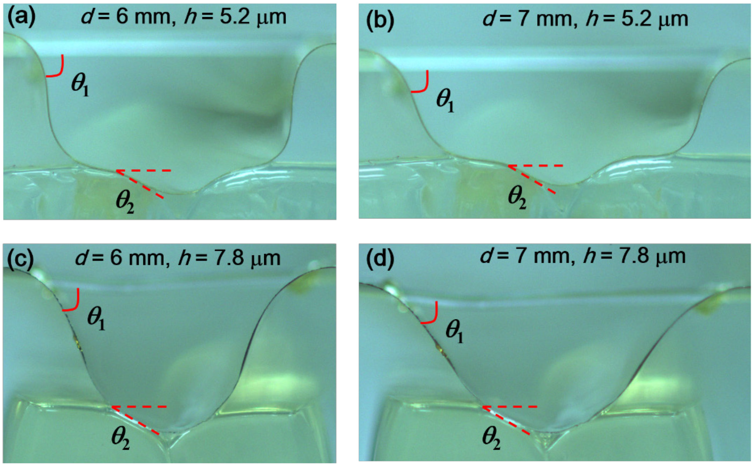
Like the cases of the featureless flat surface, the model predictions shown below are plotted as a function of the normalized length to help more explicitly illustrate the elastocapillary interactions between the membranes of different thicknesses. The single-fold total membrane length l and the hole spacing s are fixed at 7 mm and 1.5 mm, respectively.
Figure 12 shows representative optical images of the polyimide membranes. For a given deployment factor, as the thickness of the membrane increases (and, hence, as the normalized length decreases), the two bending angles θ1 and θ2 decrease.
Figure 13a,b shows the predicted and measured bending angles θ1 and θ2 as a function of the normalized membrane length. The general qualitative trend for θ1 is similar to that for the featureless flat surfaces. Larger normalized membrane lengths lead to larger bending angles and, therefore, higher conformality. For the given set of the deployment factors and the radii of curvature of the sulci examined here, normalized lengths of the order of 20 and greater are necessary to achieve good conformality over the surface of the sulcus. The results of three different cases are shown in Figure 13: (I) Df = 0, Sf = 1 (Rs = 1.5 mm); (II) Df = −1/3, Sf = 1; (III) Df = 0, Sf = 4/3 (Rs = 2 mm).
Figure 12. Optical images of the membranes in contact with a surface incorporating a single valley for different deployment factors and normalized lengths.
Micromachines 05 00528 g012
Figure 13. Modeling and experimental results of the bending angles (a) θ1 and (b) θ2 of the membranes in contact with a surface incorporating a sulcus as a function of the normalized length.
Micromachines 05 00528 g013
Figure 14 shows the predicted and measured bending angles θ1 and θ2 as a function of the deployment factor when Sf = 1. For a normalized radius of curvature Sf of 1, the deployment factor has a significant effect on the top bending angle θ1, but a much smaller effect on the bottom bending angle θ2 (Case I and II). However, for a given deployment factor Df = 0, θ2 is a strong function of Sf, whereas θ1 is only a weak function of Sf (Case I and III). The presence of the valley reduces the length of the top membrane segments (adjacent to the wires) and, thereby, decreases the top bending angle when compared with the membrane on the featureless flat surfaces.
Comparing Figure 8a and Figure 14a, especially for the case with the smallest dimensionless membrane length l/LEC of six, we note that the bending angle decreases more rapidly with the increasing deployment factor for the surface with a sulcus than the featureless flat surface. When the spatial extent of the sulcus is sufficiently small, the top membrane segments are separated by the flat segments from the bottom segments covering the sulcus. Therefore, the geometric details of the sulcus do not significantly influence the top bending angle. In contrast, θ2 is dependent on the sulcus dimension, increasing with Sf.
Figure 15a,b shows the two bending angles as a function of the normalized radius of the sulcus. As the normalized sulcus radius increases, the bending angle θ1 decreases, whereas bending angle θ2 increases. A larger valley radius causes a longer portion of the membrane to be bent along the valley surface and, thus, a larger bending angle θ2. Since the total membrane length is fixed, the effective membrane length is reduced and, thus, the bending angle θ1 is decreased.
Figure 14. Modeling and experimental results of the bending angles (a) θ1 and (b) θ2 as a function of the deployment factor.
Micromachines 05 00528 g014
Figure 15. Modeling and experimental results of the bending angles (a) θ1 and (b) θ2 as a function of the sulcus length factor.
Micromachines 05 00528 g015
Figure 16 shows the calculated membrane utilization and coverage ratios as a function of the normalized membrane length for different values of the deployment factor Df. For a given combination of the deployment factor and the hole spacing, as the normalized length increases, the membrane is more readily deformed and, thus, has a larger coverage and utilization ratios. However, the presence of a valley (or sulcus) reduces the effective length of membrane when compared with the featureless flat surface. Therefore, the membrane is less deformed and has smaller coverage and utilization ratios than a surface without a valley. Similar to the featureless flat surface, the deployment factor also affects the coverage and utilization ratios in different ways. As the deployment factor increases (i.e., Sf = 1.5 in Figure 16b) or the normalized sulcus radius increases (i.e., Df = −0.3 in Figure 16b), the utilization ratio monotonically increases. The coverage ratio, in contrast, decreases with the increasing deployment factor (i.e., Sf = 1.5 in Figure 16a) or increasing normalized sulcus radius (i.e., Df = −0.3 in Figure 16a) when the normalized length is large (l/LEC > 15 in Figure 16a). However, when the normalized length is small (l/LEC < 12 in Figure 16a), the coverage ratio increases with the increasing deployment factor or increasing normalized sulcus radius. This can be once again explained by the asymmetric behavior of the coverage ratio between when the bending angle θ1 < 90° and when θ1 > 90°. The surface contact length increases with the deployment distance d when θ1 < 90°, whereas it decreases with d when θ1 > 90° for given values of l and s.
Figure 16. Predicted values of (a) the membrane coverage ratio and (b) the utilization ratio as a function of the normalized length for different combinations of the deployment factor and the normalized sulcus radius.
Micromachines 05 00528 g016

4.3. Design Flow of the Deployable Device

The geometric parameters of the device (l, s, d and h), the mechanical properties of the membrane (E, v) and, if applicable, the surface tension of the liquid (γlg) must be selected to ensure successful device operation under the constraints and requirements of a specific application. Details of the design process flows differ for different applications. As an illustrative example, we present below a design process for a subdural ECoG device that can be introduced into and deployed along a gap between the skull and the cortical surface of a patient through minimally-invasive procedures.
In this subdural application, the gap hg between the skull and the cortical surface (typically 1–2 mm) determines the maximum acceptable height hmax of the device in its collapsed state. Assuming that the membrane segments located between two adjacent holes are bent to form hemispherical arcs in the collapsed state (Figure 17a), one can then write:
h max l 2 + s π h g
The initial deployment distance of a single fold of the membrane (in the collapsed state) may be approximated as d0 ≈ 2s/π. Smaller values of s are therefore preferred to make the device more compact in its collapsed state and also to make more of the membrane surface available for functional ECG electrodes. In practice, the minimum value of s is limited by the precision of a manufacturing technique and typically:
ssmin ≈ 2rhole
where rhole is the radius of the holes. With s set at its minimum value, one can determine the maximum acceptable value of l using Equation (17).
Next, one needs to ensure that the membrane can achieve sufficient conformal contact with a sulcus of the cortical surface by setting a minimum acceptable value of the non-dimensionalized sulcus radius (Sf)min:
S f = 2 R s d S f min
This places one limit on the achievable deployment distance dtarget in the fully-deployed state of the device:
d target < 2 R s S f min
If the push-pull wires are not allowed to bend down under the fully-deployed state, there is another limit on the achievable deployment distance dtarget one needs to consider to ensure that the membrane extends below the bottom surface of the stem and thereby maintains contact with the cortical surface (Figure 17b):
d target < 2 ( l 2 4 h w 2 ) 0.5
By considering trade-offs with the membrane utilization ratio or the membrane coverage ratio as illustrated in Figure 16, one then determines the minimum acceptable value of the membrane normalized length (l/LEC)min and hence the maximum acceptable value of the elastocapillary length (LEC)max.
The elastocapillary length is a function of the bending modulus of the membrane and the surface tension coefficient of the interfacial liquid, which may be a cerebrospinal fluid or a saline solution. For general engineering applications, one may choose low-volatility liquids of high surface tension coefficients γ and of negligible health or environmental hazard (e.g., glycerol). For a given interfacial liquid, the maximum acceptable value of the bending modulus of the membrane is:
Bmax = γLECmax2
A membrane material with a small Young’s modulus is generally preferred to minimize the bending stiffness and, thereby, increase the maximum acceptable membrane thickness. Practical values of the membrane thickness are limited by the requirements of manufacturing and device reliability/robustness. The value of the thickness is then chosen satisfying these requirements.
Figure 17. The initial collapsed state (a) and the full deployment state (b) of the device.
Micromachines 05 00528 g017

5. Conclusions

We report a design and mechanical model for a deployable planar micro-device. The device consists of a foldable membrane suspended between semi-flexible stems via push-pull wires for controlled deployment. The geometric profiles of the membrane under different device geometric parameters and contact surface topography are modeled based on the minimization of the total (elastic and surface) energy. The models are then used to predict the bending angles and the spatial coverage of the membrane. Experimental results show good agreement with the model prediction. Our work proves the early feasibility of our deployable and conformal planar micro-devices. This and related device architectures may enable new generations of devices for smart minimally invasive biomedical procedures and other engineering applications.

Acknowledgments

The article is based in part on work supported by the grant (CBET-1048726) from the NSF-DOE joint program.

Author Contributions

J. Zhuang performed the analytical modeling and experimental validation. Y.S. Ju designed and supervised the project. The two authors interpreted results and wrote the manuscript together.

Conflicts of Interest

The authors declare no conflict of interest.

References

  1. Puig, L.; Barton, A.; Rando, N. A review on large deployable structures for astrophysics missions. Acta Astronaut. 2010, 67, 12–26. [Google Scholar] [CrossRef]
  2. Gruber, P.; Häuplik, S.; Imhof, B.; Özdemir, K.; Waclavicek, R.; Perino, M.A. Deployable structures for a human lunar base. Acta Astronaut. 2007, 61, 484–495. [Google Scholar]
  3. Kuribayashi, K.; Tsuchiya, K.; You, Z.; Tomus, D.; Umemoto, M.; Ito, T.; Sasaki, M. Self-deployable origami stent grafts as a biomedical application of Ni-rich TiNi shape memory alloy foil. Mater. Sci. Eng. A 2006, 419, 131–137. [Google Scholar] [CrossRef]
  4. Guo, Z.; Kim, K.; Lanzara, G.; Salowitz, N.; Peumans, P.; Chang, F.K. Micro-Fabricated, Expandable Temperature Sensor Network for Macro-Scale Deployment in Composite Structures. In Proceedings of the 2011 IEEE Aerospace Conference, Big Sky, MT, USA, 5–21 March 2011; pp. 1–6.
  5. Jordan, B.L.; Batalin, M.A.; Kaiser, W.J. NIMS RD: A Rapidly Deployable Cable Based Robot. In Proceedings of the 2007 IEEE International Conference on Robotics and Automation, Roma, Italy, 10–14 April 2007; pp. 144–150.
  6. Kim, D.H.; Lu, N.; Ghaffari, R.; Kim, Y.S.; Lee, S.P.; Xu, L.; Wu, J.; Kim, R.H.; Song, J.; Liu, Z.; et al. Materials for multifunctional balloon catheters with capabilities in cardiac electrophysiological mapping and ablation therapy. Nat. Mater. 2011, 10, 316–323. [Google Scholar] [PubMed]
  7. Sandmann, G.H.; Ahrens, P.; Schaeffeler, C.; Bauer, J.S.; Kirchhoff, C.; Martetschläger, F.; Müller, D.; Siebenlist, S.; Biberthaler, P.; Stöckle, U.; et al. Balloon osteoplasty—A new technique for minimally invasive reduction and stabilisation of Hill-Sachs lesions of the humeral head: A cadaver study. Int. Orthop. 2012, 36, 2287–2291. [Google Scholar] [PubMed]
  8. Mimoun, B.; Henneken, V.; van der Horst, A.; Dekker, R. Flex-to-rigid (F2R): A generic platform for the fabrication and assembly of flexible sensors for minimally invasive instruments. IEEE Sens. J. 2013, 13, 3873–3882. [Google Scholar]
  9. Kim, D.H.; Lu, N.; Ma, R.; Kim, Y.S.; Kim, R.H.; Wang, S.; Wu, J.; Won, S.M.; Tao, H.; Islam, A.; et al. Epidermal electronics. Science 2011, 333, 838–843. [Google Scholar] [CrossRef] [PubMed]
  10. Py, C.; Reverdy, P.; Doppler, L.; Bico, J.; Roman, B.; Baroud, C.N. Capillary origami: Spontaneous wrapping of a droplet with an elastic sheet. Phys. Rev. Lett. 2007, 98, 156103. [Google Scholar] [CrossRef] [PubMed]
  11. Guo, X.; Li, H.; Ahn, B.Y.; Duoss, E.B.; Hsia, K.J.; Lewis, J.A.; Nuzzo, R.G. Two- and three-dimensional folding of thin film single-crystalline silicon for photovoltaic power applications. Proc. Natl. Acad. Sci. USA 2009, 106, 20149–20154. [Google Scholar] [CrossRef] [PubMed]
  12. Huang, J.; Davidovitch, B.; Santangelo, C.D.; Russell, T.P.; Menon, N. Smooth Cascade of Wrinkles at the Edge of a Floating Elastic Film. Phys. Rev. Lett. 2010, 105, 038302. [Google Scholar] [CrossRef] [PubMed]
  13. Takahashi, K.; Sugita, S.; Oshima, S.; Inaba, K.; Kishimoto, K. Evaluation of capillary-induced deformation of thin plates due to liquid column formation. Appl. Phys. Lett. 2013, 103, 043113. [Google Scholar] [CrossRef]
  14. Landau, L.D.; Lifshitz, E.M. Theory of Elasticity; Elsevier: Moscow, Russia, 1986. [Google Scholar]
  15. Timoshenko, S.; Woinowsky-Krieger, S. Theory of Plates and Shells, 2nd ed.; McGraw-Hill Book Company: New York, NY, USA, 1959. [Google Scholar]
  16. Johnson, K.L.; Kendall, K.; Roberts, A.D. Surface energy and the contact of elastic solids. Proc. R. Soc. Lond. Math. Phys. Sci. 1971, 324, 301–313. [Google Scholar]
  17. Roman, B.; Bico, J. Elasto-capillarity: Deforming an elastic structure with a liquid droplet. J. Phys. Condens. Matter 2010, 22, 493101. [Google Scholar] [CrossRef] [PubMed]
  18. Yeager, J.D.; Phillips, D.J.; Rector, D.M.; Bahr, D.F. Characterization of flexible ECoG electrode arrays for chronic recording in awake rats. J. Neurosci. Methods 2008, 173, 279–285. [Google Scholar] [CrossRef] [PubMed]
  19. Surface Energy Data for Polyimide. Available online: http://www.accudynetest.com/polymer_surface_data/polyimide_kapton.pdf (accessed on 18 July 2014).
  20. Matienzo, L.J.; Egitto, F.D. Polymer oxidation downstream from oxygen microwave plasmas. Polym. Degrad. Stab. 1992, 35, 181–192. [Google Scholar] [CrossRef]
  21. Mittal, K.L. Polymer Surface Modification: Relevance to Adhesion; Brill: Boston, MA, USA, 2009. [Google Scholar]
  22. Polyimide Film General Specifications. Available online: http://www2.dupont.com/Kapton/en_US/assets/downloads/pdf/Gen_Specs.pdf (accessed on 18 July 2014).
  23. Chen, Z.J.; Broaddus, W.C.; Viswanathan, R.R.; Raghavan, R.; Gillies, G.T. Intraparenchymal drug delivery via positive-pressure infusion: experimental and modeling studies of poroelasticity in brain phantom gels. IEEE Trans. Biomed. Eng. 2002, 49, 85–96. [Google Scholar] [CrossRef] [PubMed]

