1. Introduction
Polydimethylsiloxane (PDMS) is an elastomeric silicone material that is widely used for rapid prototyping microfluidic systems and cell-chip devices, due to its chemical inertia, thermal stability, permeability to many gases, simple preparation, optical transparency, and low cost [
1]. It can be easily integrated with electrodes, heaters, and sensors, which are fabricated on substrates, to generate multifunctional devices for biomedical applications [
2]. SU-8 is an epoxy-based negative photoresist initially developed for the microelectronics industry [
3]. Currently, SU-8 becomes widespread in the development of microfluidic devices due to its ease of use, the high aspect ratio it allows to create, its high chemical stability, and mechanical properties [
4]. It has become a material of choice for microelectromechanical systems (MEMS) and microfluidics, from the fabrication of single components to complete lab-on-chip devices [
5]. Since PDMS and SU-8 are both popular materials in the microfabrication field [
2,
3], researchers have started to integrate PDMS and SU-8 together more and more to benefit from both of their advantages [
6,
7,
8]. In the fabrication of microfluidic devices made of PDMS, the PDMS component is generally bonded to a glass coverslip to obtain closed microfluidic channels by using an oxygen (O
2) plasma surface treatment on the PDMS and glass surfaces. This results in a permanent covalent siloxane (Si-O-Si) bond between the PDMS and glass surfaces. However, using O
2 plasma is not sufficient to bond PDMS and SU-8 surfaces irreversibly as the oxidation of the SU-8 surface does not result in the creation of -SiOH groups.
Recently, different bonding methods for PDMS and SU-8 have been reported in the scientific literature, such as nitrogen plasma treatment [
9] or spin coating SU-8 on the PDMS surface [
6]. Nevertheless, nitrogen plasma is not available in all labs, and spin coating, which requires layer-by-layer processing during device fabrication, does not provide the flexibility of bonding two fabricated individual devices. Some researchers also choose to bond PDMS and SU-8 reversibly [
10]. However, for long-term cell culture devices where liquid leakage is to be avoided during the whole duration of the experimentation, a solid sealing is necessary which reversible bonding cannot provide. Instead of aligning the devices every time before each use, in the case of reversible bonding, irreversible bonding can also save time and effort on repeating micro-scale design alignment for the devices before each use as this step is time-consuming. As it is increasingly demanded of integration between PDMS and SU-8 devices, irreversible bonding of PDMS and SU-8 becomes an important technology.
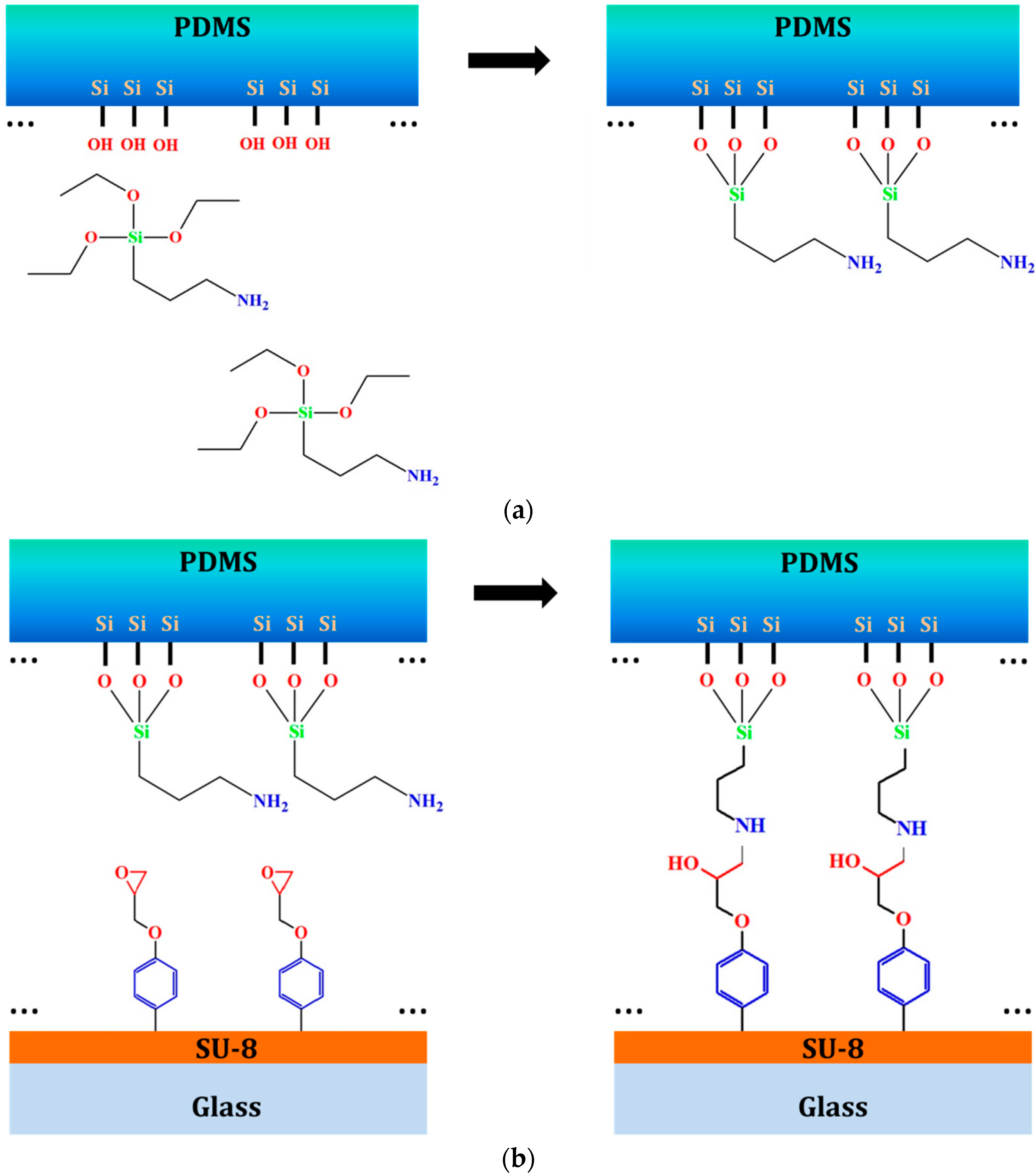
Silanization is one of the widely-applied surface modification methods. It generates a self-assembled monolayer of alkoxysilane molecule, which has methoxy (CH
3O-), or ethoxy (CH
3CH
2O-) groups onto a substrate. Aminosilane, one of the alkoxysilane molecules, has an amino (NH
2-) group as well. Aminosilane-mediated silanization has been applied on silica surfaces as a coupling agent for functionalization due to its bifunctional nature [
11]. (3-Aminopropyl)triethoxysilane (APTES) is one of the highly-selective effective aminosilanes, which has been widely applied in bonding materials for microdevice fabrication and protein immobilization for biological applications [
12,
13,
14]. It has been used for bonding PDMS to various thermoplastic materials including polycarbonate (PC), cyclic olefin copolymer (COC), polymethylmethacrylate (PMMA), polystyrene (PS) and others [
12,
15,
16]. SU-8 is an epoxy-based negative photoresist and the epoxy groups that remain on the SU-8 surface could be sufficient to react with the aminosilane molecule from the PDMS surface and form a covalent bond. In this way, PDMS and SU-8 bonding can be realized by introducing APTES molecules between the two materials (
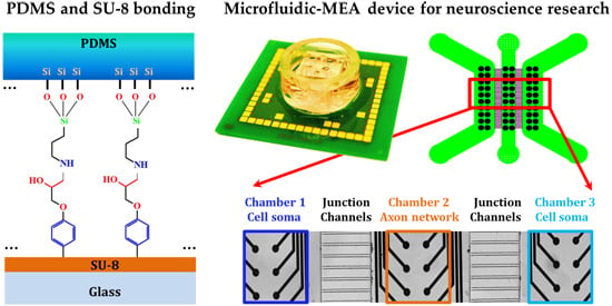
Figure 1).
In this paper, we try to find a simple and reliable bonding method for PDMS and SU-8, based on the elements and chemical bonds from the modified PDMS surface through the XPS analysis and the tensile strength test for the SU-8 processed with and without a hard bake step. In addition, we detail this bonding method with a practical microfluidic device example. This device combines a compartmentalized microfluidic device made of PDMS and a microelectrode array (MEA) neural activity recording device with SU-8 as its insulation layer. We name it a microfluidic-MEA device. The design of the electrode array is adapted to the compartmentalized design from the microfluidic PDMS device. This allows us to distinguish the neural activity from different cell populations, which can potentially present different disease status. Axons can be isolated from the neuronal network and be recorded separately. This combination of compartmentalized PDMS device and MEA device provides a multifunctional platform for neuroscience research. Our bonding technology is used to bond the PDMS and SU-8 surfaces irreversibly for this microfluidic-MEA device. The cell compatibility of this bonding method is proved through neural electrophysiological results using this integrated device. It is promising to apply this simple and reliable irreversible bonding method to integrate microdevices with PDMS and SU-8 surfaces for biological use. This type of microfluidic-MEA device has proved an innovative tool for neural electrophysiological studies.
Figure 1.
Theoretical reactions during the bonding. (a) Reaction between APTES molecule and the O2 plasma activated PDMS surface and (b) reaction between the -NH2 group from the APTES molecule on the PDMS surface and the epoxy group from the SU-8 surface.
Figure 1.
Theoretical reactions during the bonding. (a) Reaction between APTES molecule and the O2 plasma activated PDMS surface and (b) reaction between the -NH2 group from the APTES molecule on the PDMS surface and the epoxy group from the SU-8 surface.
2. Materials and Methods
2.1. Experimental Materials
PDMS Sylgard® 184 Silicone Elastomer Kit from Dow Corning Corporation (Midland, MI, USA) was sold as two components, the PDMS base and its curing agent. SU-8 (GM 1060) was ordered from Gersteltec Sàrl (Pully, Switzerland). (3-Aminopropyl)triethoxysilane 99% (APTES) was purchased from Sigma-Aldrich GmbH (Buchs, Switzerland).
2.2. Bonding Test Preparation
In this irreversible bonding method, APTES molecules, which are both CH3CH2O- and NH2- terminated, are bound both to the PDMS and SU-8 interfaces. The CH3CH2O- group reacts with the -SiOH group from the O2 plasma activated PDMS. The NH2- group from the other end of the APTES molecule reacts with the epoxy group on the SU-8 surface. Two factors that play important roles during this bonding process were investigated experimentally: (1) the way the silanization is carried out, either in a liquid-phase or vapor-phase method; and (2) the degree of reticulation of SU-8 achieved before performing the PDMS and SU-8 bonding step. These two factors have effects on the efficiency of bringing APTES molecules on the PDMS surface and the amount of epoxy groups on the SU-8 surface after the baking process, respectively. Since the microfluidic device bonded with this method will be used for neural cell culture in the future, and the neurons will grow on the surface of SU-8, we decided to have the surface modification on the PDMS surface instead of the SU-8 surface to have less effect on the cell culture.
We prepared our test samples by a combination of PDMS and SU-8 samples under different processed conditions: for the PDMS surfaces, they were first activated by O
2 plasma (50 W, 0.6 mbar, 30 s) to create the -SiOH group on the PDMS surface. After the surface activation, the APTES molecules were brought in contact with the activated PDMS surface immediately. In the literature, different methods to achieve a surface silanization using APTES have been described, such as liquid-phase silanization with deionized (DI) water followed by heating to a temperature of 85 °C [
17], or by mixing with anhydrous toluene [
13] or ethanol [
12] and vapor-phase silanization [
18]. To avoid the use of toxic chemicals, such as toluene [
19], and provide a bonding method that is compatible with the requirements of the cell culture on a chip, we decided to use directly 99% APTES in liquid-phase or vapor-phase for the silanization step. The protocol we used for liquid-phase silanization is the following: PDMS surface was immersed for 5 min into 99% APTES immediately after the O
2 plasma, then washed in DI water and dried. The protocol for vapor-phase silanization is the following: PDMS samples were exposed for 0.5 h or 1.0 h of APTES vapor by placing them into a desiccator containing a few drops of liquid 99% APTES and reaching a vacuum environment so that APTES evaporates.
To obtain SU-8 surfaces showing different degrees of reticulation, some samples were used in the bonding tests without hard bake, while others were submitted to a 2 h hard bake at 150 °C on a hotplate. XPS analysis was performed on the surface of the PDMS obtained by different silanization methods, including vapor-phase and liquid-phase. The bonding strength was evaluated for different degrees of reticulation for the SU-8, including SU-8 with and without the hard bake process.
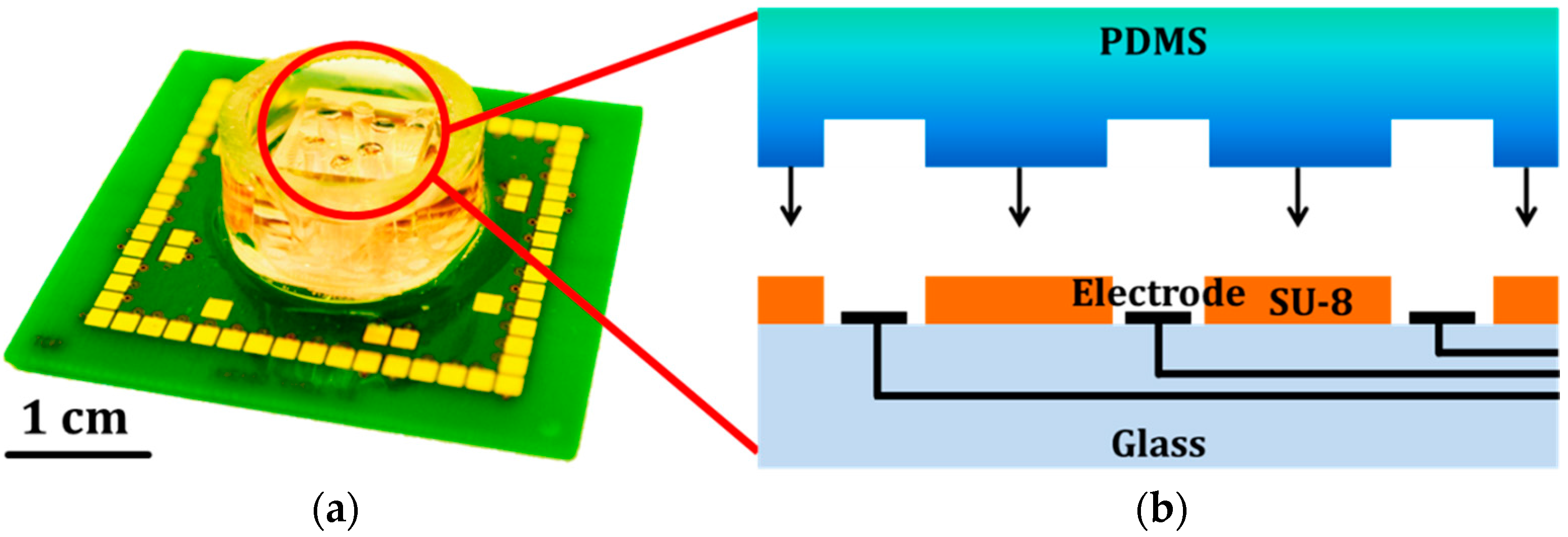
2.3. Fabrication of Our Integrated Microfluidic-MEA Device
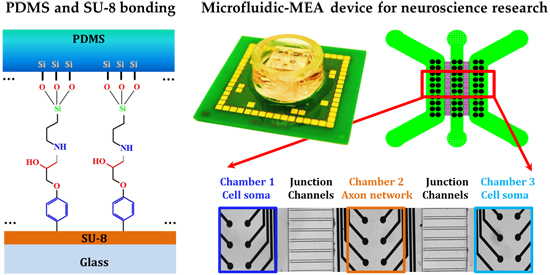
In order to demonstrate the simplicity of this bonding method and prove its satisfying performance with a real case for long-term biological use, we describe here the detail of this bonding method with our integrated microfluidic-MEA device. This device combines a microfluidic device made of PDMS and a MEA device with a 5 μm layer of SU-8 as an insulation layer on its top (
Figure 2). The PDMS microfluidic device provides the compartmentalized chambers for neuronal culture and the MEA device provides electrodes at the bottom of the chambers allowing neural activity recording. This type of integrated device is designed for electrophysiological studies from compartmentalized neuronal culture [
20]. In the following, we will detail the fabrication of this device.
For the compartmentalized PDMS device fabrication, the PDMS base and the curing agent were mixed at a ratio of 10:1. The mixture was poured onto a silicon wafer with structured patterns, degassed in a desiccator for 20 min until the air bubbles were gone, and cured in an oven at 80 °C for 1 h to solidify the PDMS mixture and replicate the pattern on the surface of the PDMS device. Subsequently, a PDMS puncher was used to perforate the PDMS device to create reservoirs, which connect the microchannels to the macro world for the injection of fluids into the device. The PDMS surface was first cleaned using adhesive tape to remove small particles generated from the hole-punching step. It was then sonicated in an ultrasonic bath for 5 min and the surface was dried. The PDMS device was placed in the O
2 plasma machine to activate the surface (50 W, 0.6 mbar for 30 s). This surface modification step creates -SiOH groups on the PDMS surface. Afterwards, the PDMS device was immediately immersed into the 99% APTES solution for 5 min and then washed with DI water and dried. The CH
3CH
2O- groups from APTES molecule can attach and react with the -SiOH group from the activated PDMS surface and form a covalent Si-O-Si bond [
21].
Figure 2.
The microfluidic-MEA device for neural cell culture. (a) Picture of this integrated microfluidic-MEA device bonded with our PDMS and SU-8 bonding method; and (b) schematic of the cross-section of the device.
Figure 2.
The microfluidic-MEA device for neural cell culture. (a) Picture of this integrated microfluidic-MEA device bonded with our PDMS and SU-8 bonding method; and (b) schematic of the cross-section of the device.
For the MEA part in this microfluidic-MEA device, the SU-8 epoxy photoresist was coated on top of the electrode wires, as it acts as an insulation layer between the cell layer and the electrode array layer (
Figure 2b). Polymer coatings, such as SU-8, on metals are widely used for insulation and protection for circuit board and wires in electronic devices to provide high electrical insulation and protection from environmental damage [
22]. This SU-8 insulation layer is essential for this neural activity recording device because it can also reduce the parasitic capacitance between the electrode wires and the culture medium (conductive saline solution) for better signal recording [
23]. A 5 μm thick layer of SU-8 was first spin-coated on the MEA surface, and baked by a hot plate at 60 °C for 15 min and another 15 min at 95 °C for a soft bake. Then it was exposed to UV light and polymerized by a hot plate at 80 °C for 20 min for a post-exposure bake, and developed in PGMEA solvent. The SU-8 surface (without the hard bake process) from the MEA device also needs to be cleaned using isopropyl alcohol to remove the residual particles on the surface. Subsequently, the SU-8 surface was carefully rinsed by DI water and dried.
When the surface modification of the PDMS device has finished, the PDMS device was taken out of the APTES solution, washed by DI water and dried. Then the PDMS device was immediately aligned onto the MEA device under a microscope without touching the silanized surface before alignment was achieved. Afterwards, the microfluidic-MEA device was placed on a flat surface inside an oven and a pressure of 2 N/cm
2 was applied on the top of the device to generate a force between the PDMS and MEA parts to keep these two surfaces fully in contact. The temperature of the oven was slowly increased with a ramp of 2 °C per min to 150 °C and kept at 150 °C for 1 h. Then, the temperature was decreased back to 30 °C naturally. The reason for increasing and decreasing the temperature slowly is to avoid structural deformations, as well as the generation of cracks inside the SU-8 material, which would create leakage. During this bake time, a chemical reaction occurs between the -NH
2 group from the APTES molecule on the PDMS surface and the epoxy group from the SU-8 surface [
24]. The bonding for this integrated microfluidic-MEA device was completed.
2.4. Primary Cortical Neurons Preparation
Mouse primary cortical neurons were prepared from embryonic day 17 mouse fetal brains. Cortices were digested in a media containing the enzyme papain (20 U/mL, Sigma-Aldrich GmbH, Buchs, Switzerland) and dissociated by mechanical trituration. Cells were plated in neural cell culture medium: neurobasal medium supplemented with 2% B27, 1% L-glutamine, and 1% penicillin/streptomycin. Cells were plated in polyethyleneimine (PEI, 0.05%, v/v) and laminin (20 μg/mL) coated microfluidic devices and were kept at 37 °C in a humidified 5% CO2 atmosphere. PEI (50%, w/v) and laminin were purchased from Sigma-Aldrich GmbH (Buchs, Switzerland). All the materials used for cell culture were purchased from Invitrogen (LuBioScience GmbH, Lucerne, Switzerland).
3. Results and Discussion
3.1. Analysis of Chemical Reactions on the PDMS
In order to prove the APTES molecules were bound onto the PDMS surface by liquid- and vapor-phase silanization, the elements and the chemical bonds on the PDMS surfaces have been determined by XPS analysis. The samples were analyzed using an ESCA KRATOS AXIS ULTRA Surface Analysis System. Data were analyzed by software MultiPak Version 9.5 (ULVAC-PHI Inc., Chigasaki, Japan). All spectra were calibrated in reference to the aliphatic C 1s component at a binding energy of 285.0 eV [
25].
Among all the molecules present in the bonding protocols studies here, the N 1s is only present in the -NH
2 group of the APTES molecule, so its presence in the XPS spectra proves the presence of the APTES molecule on the tested sample.
Figure 3 shows the N 1s binding energy from different samples: Sample 1 corresponds to a PDMS sample without any chemical surface treatment, Sample 2 is a liquid-phase silanized sample under 5 min immersion in 99% APTES, Samples 3 and 4 are vapor-phase-silanized PDMS surfaces, exposed for 0.5 h and 1.0 h to the APTES vapor, respectively. A peak in the XPS spectra close to an energy of 400 eV corresponding to the C-NH
2 bond can be seen only for Sample 2, proving the efficiency of the liquid-phase silanization method. No significant peak at this value of the energy can be observed for the other samples, which indicates that tested vapor-phase silanization of PDMS is inefficient in our experiment. Interestingly, the composition measurement of the main elements from Sample 2 (C 1s 44.7%, O 1s 30.9%, N 1s 7.3%, Si 2p 17.1%) is very close to the main elements composition of the APTES molecule (C 1s 48.9%, O 1s 21.7%, N 1s 6.3%, Si 2p 12.7%). This is a further indication of the presence of the APTES molecules on the surface of this PDMS sample after the liquid-phase silanization.
Figure 3.
The N 1s spectra of the PDMS surfaces by XPS under different surface modifications.
Figure 3.
The N 1s spectra of the PDMS surfaces by XPS under different surface modifications.
3.2. Manual Tensile Strength Test
SU-8 without hard bake can provide a larger number of epoxy groups and better contact for adhesion, which can potentially achieve a better bonding quality. To verify the difference of SU-8 with and without hard bake in our bonding method, we performed a manual tensile strength test on the assembled PDMS and SU-8 samples obtained by combining PDMS samples resulting from liquid-silanization of APTES and SU-8 samples with and without hard bake. The samples submitted to the tensile test were prepared by bonding a 1 cm diameter PDMS device to a 5 μm thick layer of SU-8 deposited on glass (
Figure 4a,b). The contact surface between PDMS and SU-8 was 0.785 cm
2 in circular shape. The surface of the PDMS device was activated by O
2 plasma and processed with liquid-phase APTES surface silanization. SU-8 samples with and without hard bake were both individually bonded with the modified PDMS device and tested in this tensile strength test. The testing set-up (
Figure 4c) was built manually. As shown in
Figure 4c, a scale carrying a piece of metal of 3.530 kg was attached to a transparent plastic holder with a square hole on its top to maintain the tested the PDMS sample part. A lifting-jack was inserted between the plastic holder and the glass part of the tested sample, moved in the vertical direction and can lift up to 6 kg (
Figure 4d). With this set-up, by lifting up the SU-8-coated glass part of the sample, we created a separating force between the SU-8 and the PDMS that was attached to the metal plate. This force was measured by the change of mass indicated by the scale. With this tensile strength test, we observed the difference in bonding strength between the SU-8 with and without hard bake. The samples combined with hard baked SU-8 broke at the interface of PDMS and SU-8 during the lifting by the lifting-jack. However, the samples combined with SU-8 without hard bake showed a good adhesion until the separation process applied reached 440 kPa, without failure, which was the highest value the test set-up can provide. This is substantially higher than the working pressure for typical microfluidic devices. This manual tensile test revealed that SU-8 is required without a hard bake before contacting with the silanized PDMS surface. After the two surfaces were in contact and processed by the final baking step (150 °C for 1 h), a strong irreversible bonding which can reach 440 kPa was made between the PDMS and SU-8. This manual tensile strength test setup is flexible and convenient for quick tensile testing in the lab as a preliminary result.
Figure 4.
PDMS and SU-8 bonding testing sample (a,b), and the setup for the manual tensile strength test (c–e). (a) PDMS and SU-8 samples for the bonding strength test. (b) Schematic of the testing sample. The lower part is a piece of 1 mm thick glass coated with a 5 μm thick SU-8. The upper part is a piece of PDMS obtained by molding. This setup (c) for the manual tensile strength test includes a scale, a piece of metal mass with a plastic PDMS chip fixer on top, and a lifting-arm (c). Detail of the manual tensile test set-up during test (d) and its side view (e).
3.3. Ultimate Tensile Strength Test for the Bonding
To investigate further the limit of the tensile strength for our bonding method by using liquid-phase silanized PDMS surface and the SU-8 surface without hard bake, a tensile test machine from Walter + Bai AG (Löhningen, Switzerland) was used and the test was conducted under force control until the breaking point of the bonding. The tested sample was attached between two metal sample holders (
Figure 5). The separating force on the tested sample was increased by the machine until the PDMS and SU-8 bonding interface broke. The tensile strength force measured during the tensile strength test was 116 ± 5 N, with most of the deformation occurring on the PDMS. This result corresponds to a stress around 1.5 MPa at the point where the breaking occured. This is reasonable when we consider the tensile strength of PDMS which is much higher than this bonding breaking point [
26]. The published result of tensile strength for PDMS and SU-8 bonding reach around 1 MPa [
13]. Compared to this value, our method provided a slightly higher tensile strength of the irreversible bonding.
Figure 5.
Tensile strength test for the bonding. (a) Test sample was fixed between the two metal parts from the tensile test machine for the tensile strength test; (b) A sample during the test.
Figure 5.
Tensile strength test for the bonding. (a) Test sample was fixed between the two metal parts from the tensile test machine for the tensile strength test; (b) A sample during the test.
3.4. PDMS and SU-8 Bonding Method Applied to an Integrated Microfluidic-MEA Device
The compartmentalized PDMS device has three chambers and each chamber has two columns of 10 electrodes (
Figure 6a). Each two chambers are connected by junction channels of 20 μm width, 10 μm height and 500 μm length. The low dimensions on width and height will allow its microfluidic PDMS device to segregate the neuronal soma in one chamber and allow the axon to grow through the junction channel to the neighbor chamber. We placed mouse primary cortical neural cells into the two lateral chambers (Chambers 1 and 3) and the axons from the two lateral cell populations grew through the junction channels and built a neuronal network in the middle chamber (Chamber 2). The electrodes from the MEA device were made of platinum (50 μm diameter), which allow simultaneous recording of extracellular potentials from the neuronal culture. At the same time, both the microfluidic PDMS and MEA devices were designed to provide a good fitting of their functions and their integration (
Figure 6b).
The device needed to be sterilized before its use for cell culture. 70% ethanol was injected into the reservoirs using a syringe, which generated a flow inside the device to both wash away the particles remaining inside the chambers and junction channels and to sterilize them. It was kept inside the device for 20 min, and then sucked out by a vacuum aspirator. The ethanol was then replaced with DI water. The chambers and junction channels were washed with DI water three times and emptied by using the vacuum aspirator each time. The device was then placed in a sterile petri dish (100 mm diameter) and exposed under UV light for 1 h. Like normal neural cell culture in well plates, the cell adhesion surface inside the device needs to be treated with a coating solution for faster neuronal adhesion and more homogenous cell distribution. The coating solution, 0.05% (v/v) PEI, was injected into the device from the reservoirs and kept in the chambers and junction channels for 2 h at 37 °C inside a sterile, closed petri dish. Then, the PEI coating solution was removed and the device was washed three times with DI water and replaced with a laminin (20 μg/mL) coating solution and kept at 37 °C for another 20 min. Finally, the laminin coating solution was removed, the device was washed three times with DI water, and replaced with neural culture medium (see recipe in materials and methods section) and kept inside a petri dish in the incubator (37 °C, 95% air, 5% CO2), getting ready for the cell plating. Primary cortical neurons were extracted from E17 mouse embryos on the day of cell plating. The cell suspension was concentrated to 10 million cortical neurons per mL of neural culture medium. The prepared microfluidic-MEA device was first emptied, and then filled with the freshly-prepared cell suspension into the lateral chambers (Chamber 1 and 3), carefully avoiding air bubbles. The middle chamber (Chamber 2) which contains no cells was filled with the normal neural culture medium. The device and the freshly placed neurons were kept inside the incubator for long-term cell growth and neural network development. All the experimental procedures were carried out according to the Swiss federation rules for animal experiments.
Figure 6.
(a) Schematic of the chambers and junction channels from the PDMS device and the six columns of electrodes from the MEA device. Scale: 1000 μm; (b) Picture of the interface of PDMS and SU-8 from the device taken by wide field microscope. The functions of each part are indicated. Scale: 200 μm; (c) Neural activities recorded by 60 microelectrodes from this microfluidic-MEA device. The colors are correlated to the regions with the same colors in (b). Each sub-window corresponds to one individual electrode. The signals from Chambers 1 and 3 were recorded from cell soma region, and the axon activities were recorded by the electrodes from Chamber 2.
After two weeks of continuous culture
in vitro, a heathy neural network was built inside the microfluidic-MEA device like in a normal culture dish. Spontaneous activities from the neural network were recorded with a MEA 1060 data acquisition system (Multi Channel Systems MCS GmbH, Reutlingen, Germany) with 60 recording channels at 10 or 20 kHz sampling frequency and 10 to 3000 Hz hardware bandpass filter (
Figure 6c). Data acquisition and analysis were obtained using the MC_Rack software (Multi Channel Systems MCS GmbH). The activity signals from the neuron soma region and the axon region were recorded by the 60 electrodes (see
Video S1). The bonding could not be separated afterwards in the vast majority of cases (with very rare failures occurring possibly due to the roughness or flatness of the PDMS device surface).
Comparing to other technologies such as spin-coating SU-8 onto the PDMS surface, our bonding method is simple and convenient as shown in the example of our microfluidic-MEA device, and requires only a chemical hood and an oven. The microfluidic PDMS device and MEA device can be fabricated individually and synchronously, and integrated together at the end of the process without any limitations. This flexible combination characteristic of this bonding method allows an easy fabrication of microfluidic systems and sealed chambers based on PDMS and SU-8, while avoiding leakages and allowing the obtained systems to be re-used after being cleaned. Concerning the device re-use, the device was aspirated first, then washed with DI water and treated with trypsin after use to detach the cells. In the end, the device was emptied, dried and kept in a sterile environment until the next use.


