Article

Deformation Analysis of a Pneumatically-Activated Polydimethylsiloxane (PDMS) Membrane and Potential Micro-Pump Applications

1
ITRI South Campus, Industrial Technology Research Institute, Tainan City 70955, Taiwan
2
Department of Mechanical and Automation Engineering, I-Shou University, Kaohsiung City 84001, Taiwan
*
Author to whom correspondence should be addressed.
Micromachines 2015, 6(2), 216-229; https://doi.org/10.3390/mi6020216
Submission received: 10 November 2014 / Accepted: 21 January 2015 / Published: 29 January 2015
(This article belongs to the Special Issue Biomedical Microdevices)

Abstract

:
This study presents a double-side diaphragm peristaltic pump for efficient medium transport without the unwanted backflow and the lagging effect of a diaphragm. A theoretical model was derived to predict the important parameter of the micropump, i.e., the motion of the valves at large deformations, for a variety of air pressures. Accordingly, we proposed an easy and robust design to fabricate a Polydimethylsiloxane (PDMS)-based micropump. The theoretical model agrees with a numerical model and experimental data for the deformations of the PDMS membrane. Furthermore, variations of the generated flow rate, including pneumatic frequencies, actuated air pressures, and operation modes were evaluated experimentally for the proposed micropumps. In future, the theoretical equation could provide the optimal parameters for the scientists working on the fabrication of the diaphragm peristaltic pump for applications of cell-culture.

Graphical Abstract

1. Introduction

In recent years, micromachining technologies have been introduced to provide a means to miniaturize microfluidic applications, such as biochemical analysis [1,2,3], drug delivery [4], DNA sequencing [5], nucleic acid synthesis [6], etc. One of the most exciting developments in microfluidic applications is the rapid evolution of biological-microelectromechanical systems (Bio-MEMS). The advantages of such applications are integrating delivery, testing, and analysis of biomedical samples, therefore dramatically reducing the required human involvement in laborious multi-step sample handling and processing, and improving data quality and quantitative analysis. Microfluidic applications also reduce the overall cost and time of measurements, and at the same time, improve the sensitivity and specificity of analyses. In addition, basic microfluidic components, such as microchannels, microvalves, micropumps, micromixers and microreactors with various novel sensors and detection platforms have been successfully incorporated in the microfluidics and Bio-MEMS fields. Among them, micropumps are the most important components because they are crucial in sample delivery and manipulation in microfluidic devices and systems. The design of an efficient micropump has been a challenging task in miniaturized biomedical systems.
Micropumps can generally be classified as either non-mechanical or mechanical based on whether their components are fixed or movable, respectively. Although non-mechanical pumps have simple structures and contain no moving parts, their performance depends on the types and surface properties of the fluids. Non-mechanical pumps transport fluids by directly converting external energy into kinetic energy. Conversely, mechanical pumps require an actuation source to provide a mechanical stroke cycle. Mechanical actuation typically drives fluids by coupling mechanical deformation of a moving boundary to fluid pressure changes. Actuation mechanics may be electrostatic [7,8,9], electromagnetic [10,11], pneumatic [12,13,14], thermopneumatic [15,16], or piezoelectric [17,18,19]. The actuated diaphragms are classically divided into a single reciprocating displacement and a peristaltic displacement. A single reciprocating displacement is constructed from multi-layers of material and works as the actuated diaphragm with two check valves that prevent the backflow of fluids. Alternatively, the micropumps are actuated with three diaphragms operating in series, and accordingly, are sometimes named as peristaltic micropumps. Certainly, the choice of pump diaphragm material is particularly important. Common pump diaphragm materials include silicon, glass, and plastic. Currently, PDMS elastomers are widely used for fabricating various micro fluidic devices such as passive and active structures. Because of its excellent biocompatibility, good mechanical properties and simple structural fabrication and bounding processes, the PDMS is used as both the functional membrane and the structural substrate of micropumps.
Recently, pneumatically-actuated peristaltic micropumps [20,21,22,23,24] have proven effective for driving fluids in microchannels and are readily integrated with bio-sensing chips. In these micropump designs, fluids are typically driven by multiple elastic membranes actuated by their corresponding pneumatic chambers. However, precise control of membrane movement is critical for pumping performance. The previous micropumps [13,14,15] used various vertical actuation mechanisms and fluid control valves, which increased the complexity of the structural design and the processes needed for multiple layer alignment and assembly. Therefore, the objective of this study is to design an easily fabricated, low cost micropump with fine controls needed for accurate volumetric flow rate. Although a large number of reports of PDMS micropump applications are found in the literature, and the number of papers is still increasing, the actuated working principle and membrane deformation behavior are not clearly understood. The parameters that must be considered include the geometry of the actuated structure, material properties, and applied external energy modes. All of these factors simultaneously affect micropump performance.
Using the pneumatically-actuated PDMS membrane as a flexible structure, the study investigates deformation mechanisms and the transporting performance. Theoretical and numerical models are employed to predict and evaluate experimental values for membrane deformation mechanisms. Consequently, the proposed actuated membrane design is optimized by numerical simulations. Here we demonstrate that a micro-pump with three-pair flexible structures, i.e., with single- and double-sided flexible actuation, is successfully incorporated to transport the sample stream.

2. Design and Experiment

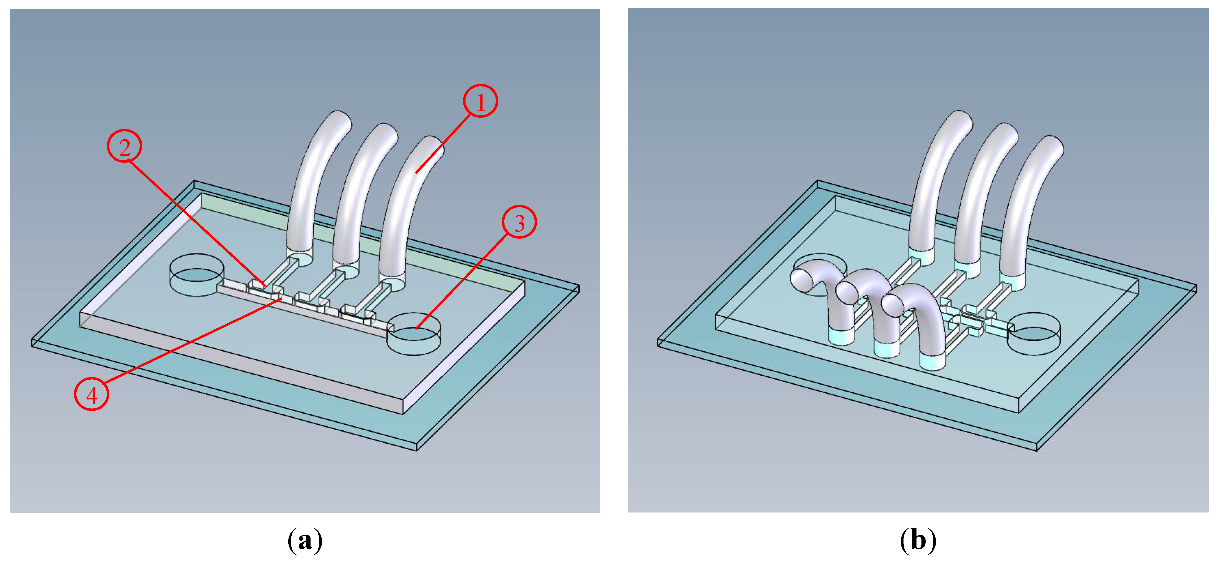
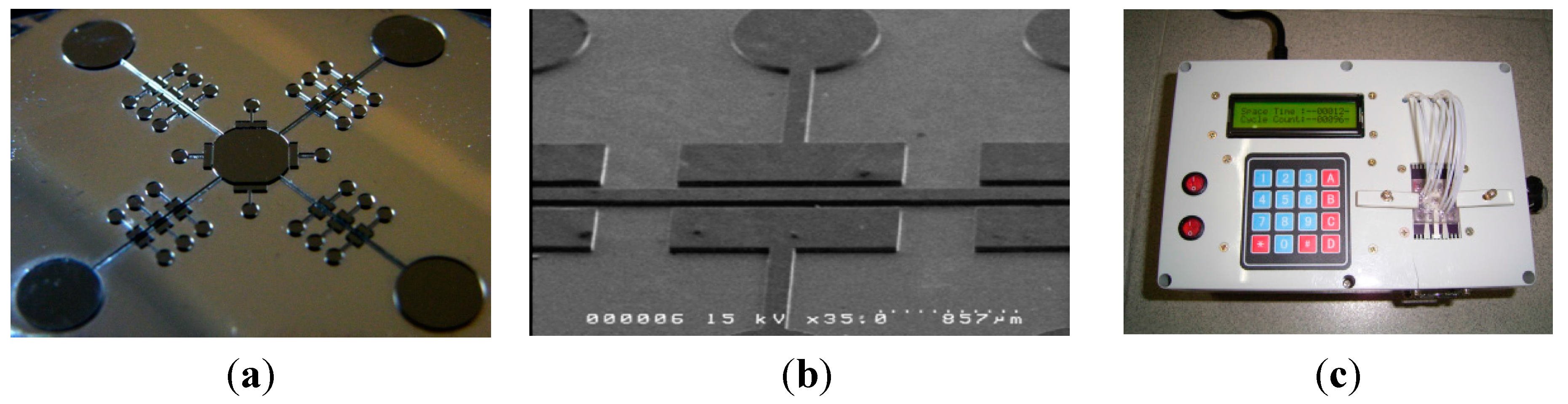
2.1. Design Principle and Fabrication

In microfluidic systems, the backflow of pumping liquid can cause cross contamination between solutions or microbial contamination [25]. Therefore, unwanted fluid backflow in the micropumps can influence the precise manipulation of fluid flow in a microfluidic system. The major contribution of this study is the design of the pneumatic side chambers that actuate the flexible structures to generate an efficient pumping performance and avoid the fluid backflow particularly for the double-side mode. The side chambers are positioned orthogonally to the fluidic microchannel, and they provide flexible structures (single- and double-side) for sample transportation (see Figure 1). Figure 2 schematically depicts how transportation by the proposed micro-pump is performed by the three-pair double-side flexible structures. The channel between the six side-chambers defines the transporting region. When atmospheric air fills the side chambers, the flexible structures are pneumatically activated by the compressed air in series to create the transporting effect. Adjusting various operation parameters, e.g., applied pressures and/or driving frequency, provides a precisely controlled pumping action.
Figure 1. Schematic representation of the proposed micropump using three-pair moving structures in (a) single-side mode and in (b) double-side mode. Here, (1) is a tubing, (2) is a buried side chamber, (3) is a reservoir, and (4) is a microchannel.
Micromachines 06 00216 g001
Figure 2. Schematic representations of a pumping process in a three-pair double-side mode micropump. Here, arrow direction indicates the air input/output. 1, 2, and 3 indicate the pair number. (a) 3 pairs simultaneously shut down to block the fluid. (b) 1st pair and (c) 2nd pair sequentially open to induce the fluid to move. (d) 1st pair and (e) 2nd pair sequentially shut down and 3rd pair open to enhance the fluid forward. (f) 3 pairs simultaneously shut down again to avoid the backflow.
Micromachines 06 00216 g002
To construct the micropump, a 250 μm-thick layer of negative photoresist SU-8 (MicroChem Corp., Newton, MA, USA) was first spun onto a silicon substrate. The SU-8 was used in the master mold in the PDMS casting process due to its excellent structural robustness, good adhesion to the silicon substrate, and suitability for producing high-aspect-ratio structures. The SU-8 master mold was formed using the standard lithography and baking processes. After fabricating the SU-8 master mold, the PDMS solution was poured into the master mold and cured at 100 °C for 10 h. The inverse structures of the SU-8 master mold were then transferred onto the PDMS chip after the de-molding process. After completing the replication process for the PDMS layer, the chip device was assembled, and an oxygen plasma treatment was used to bond the PDMS layer to the glass substrate. Figure 3a,b are close-up views of the SU-8 template. The dimensions of the pneumatic side chambers are 1500 × 400 μm2 and their depths are 250 μm. The flexible structure formed between the fluidic flow channel and pneumatic side chambers is 100 μm thick. The flow channel is 150 μm wide and 250 μm deep.
Figure 3. (a) Photograph of the SU-8 template for the micropump chip; (b) SEM image showing a close-up view of the SU-8 template; (c) photograph of the hand-held digital controller.
Micromachines 06 00216 g003

2.2. Control and Measurement System

Figure 3c is a photograph of the micropump control system, which is comprised of an air compressor (JUN-AIR Inc., MDR2-1A/11, Kawasaki-shi, Japan) for supplying compressed air to the micropump, a functional control circuit, and three electromagnetic valves (EMVs) (SMC Inc., S070M-5BG-32, Taoyuan City, Taiwan) to control the pneumatic pump. Tests were performed to measure pumping rates at various operational frequencies, pneumatic driving pressures, and operation modes. A constant current was supplied to the microflow sensor [24] throughout the tests, and the electrical signal output from the sensor was recorded by an analog-to-digital converter (ADC) (ATMEL Corp., ATMEGA8535, San Jose, CA, USA) connected to a personal computer. A syringe pump (KDScientific, KDS 100, Holliston, MA, USA) was used to calibrate the flow rate to the output voltage of the microflow sensor. The micropump was positioned under an optical microscope (Olympus, BH2-UMA, Tokyo, Japan) during testing so that fluidic motion in the microchannel could be recorded with an image capturing system (Photometrics, CoolSNAP HQ2, Tucson, AZ, USA).

3. Theoretical and Numerical Methods

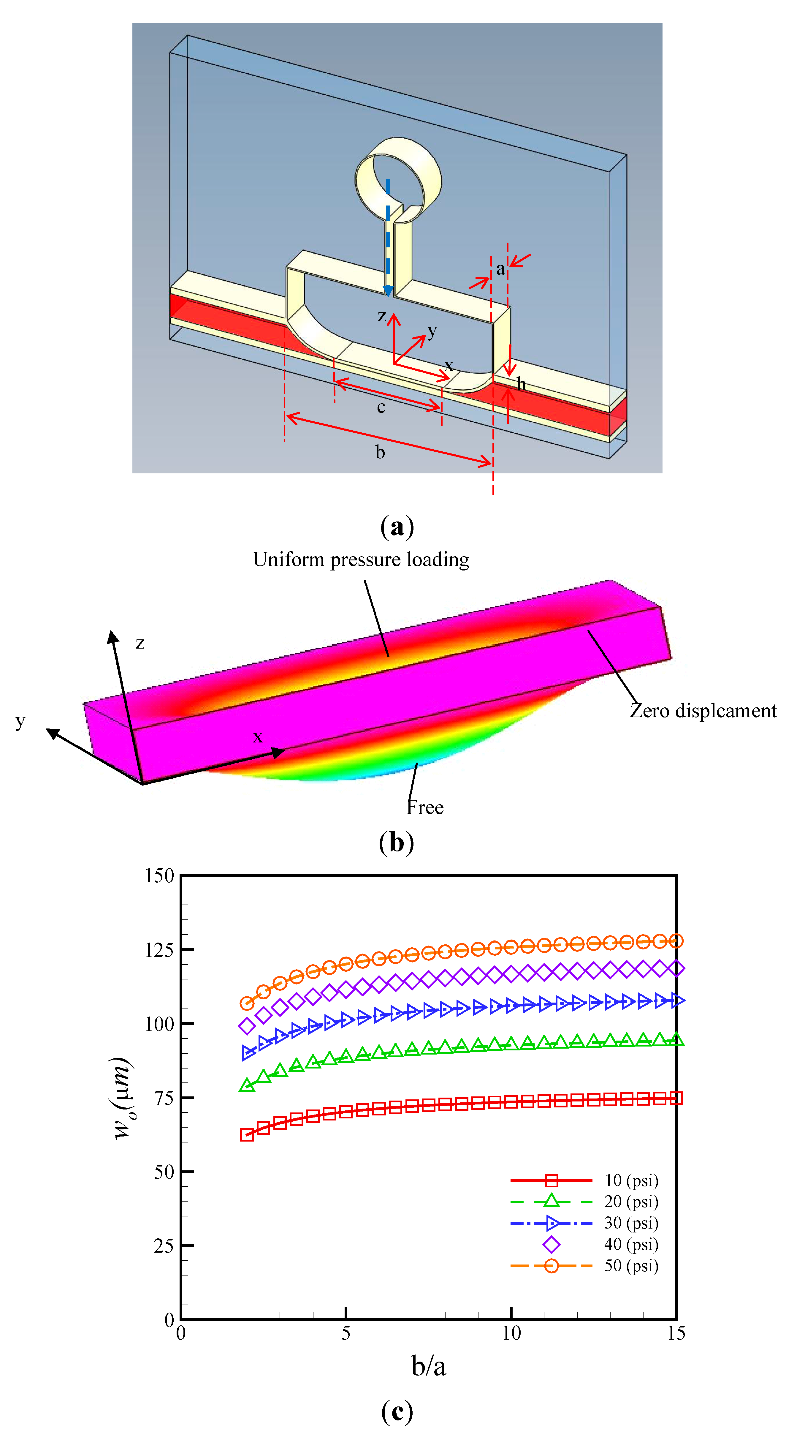
3.1. Theoretical Analysis

An approximate solution for the larger deformation of the PDMS membrane can be expressed by using the strain energy (USt) method as shown below [26]:
U S t = E h 2 ( 1 v 2 ) a / 2 a / 2 b / 2 b / 2 ( u x ) 2 + ( v y ) 2 + u x ( w x ) 2 + v y ( w y ) 2 + 1 4 [ ( w x ) 2 + ( w y ) 2 ] 2 + 2 v [ u x v y + 1 2 u x ( w y ) 2 + 1 2 v y ( w x ) 2 ] + 1 v 2 [ ( u y ) 2 + 2 u y v x + ( v x ) 2 + 2 u y w x w y + 2 v x w x w y ] } d x d y
where u, v, and w are the x-, y- and z-directional displacements, respectively. Since deformations of u and v are much smaller than that of w (u << w and v << w), deriving w is more important than deriving u and v. Moreover, the strain energy obtained by Equation (1) can be simply expressed using the following equation:
U S t = E h 8 ( 1 v 2 ) a / 2 a / 2 b / 2 b / 2 [ ( w x ) 2 + ( w y ) 2 ] 2 d x d y
here, E and h are Young module and membrane thickness, respectively. The expressions clearly satisfy the boundary conditions but contain several arbitrary parameters, which must be determined by applying virtual displacement principles. To illustrate the methods, consider a uniformly loaded rectangle membrane with the dimensions a (transversal width) and b (axial length) (Figure 4a). The steady-state solution w(x, y) for the larger membrane deformation problem is assumed by a cosine functions regarding of x- and y-directions. The solution has to be satisfied by the boundary conditions in Figure 4a:
w ( c ¯ / 2 , y ) x = 0 ;   w ( b / 2 , y ) = 0 ;   w ( x , 0 ) y = 0 ;   w ( x , a / 2 ) = 0
The displacement w can be obtained by:
w = { w 0 cos π y a 0 x c / 2 w 0 cos π y a cos π ( x c ¯ / 2 ) ( b c ¯ ) c ¯ / 2 x b / 2
here wo is the maximum value of w, c is varied with the y-axial direction and is assumed as below:
c = c ¯ cos π y a
By substituting Equations (4) and (5) into Equation (1), the strain energy can be integrated as:
U S t = E h π 4 w o 4 512 ( 1 ν 2 ) a 2 [ 128 5 π c ¯ a + 9 ( b c ¯ ) a + 2 a ( b c ¯ ) + 9 a 3 ( b c ¯ ) 3 ]
Equation (6) can be rewritten as another form as below:
U S t = E h π 4 w o 4 512 ( 1 ν 2 ) a 2 [ α b a + ( 9 α ) λ + 2 λ + 9 λ 3 ]
here α = 128 5 π ( 8.15 ) and λ = ( b c ¯ ) a .
By deriving U S t λ (implied that USt achieved the maximum value as the ( b c ¯ ) attained the minimum value), the solution obtained for λ is:
λ = ( b c ¯ ) a = 1 + 1 + 27 ( 9 α ) ( 9 α ) = 2.63
here, λ is a constant value (~2.63). The λ/2 defines the dimensionless curved-shaped length, which is dependent on the shorter side length of the rectangle. The outcome can be verified by the latter numerical calculations and experimental observations. The external pneumatic energy (UPn) produced by air pressure loading is integrated by:
U P n = a / 2 a / 2 b / 2 b / 2   P w d x d y = 2 a 2 P w o π 2 ( π 2 b 4 a + ( 2 π 2 4 ) λ )
Since the strain energy (USt) is equal to the external pneumatic energy (UPn), is performed by:
E h π 4 w o 4 512 ( 1 ν 2 ) a 2 [ α b a + ( 9 α ) λ + 2 λ + 9 λ 2 ] = 2 a 2 P w o π 2 ( β b a + γ λ )
here β = π 2 4 ( 2.47 ) and γ = 2 π 2 4 ( 0.47 ) .
Figure 4. (a) Schematic illustration of the flexible membrane, side chamber, and microchannel; (b) The boundary conditions of 3-D numerical simulation for the larger deformation; (c) Deformed profiles of flexible membrane related with the axial/transversal length (b/a) ratio under different air pressures.
Micromachines 06 00216 g004
During deforming, the membrane satisfies the principles of energy minimization in achieving equilibrium. Hence, the dimensionless maximum deformation wo/a caused by pressure loading can be estimated as:
w o a = ( 4 π ) 2 [ ( 1 ν 2 ) ( β b a + γ λ ) 4 ( α b a + ( 9 α ) λ + 2 λ + 9 λ 3 ) P a E h ] 1 3
Equation (11) can be easily calculated for the maximum deformation of the rectangle membrane for the pneumatically-driven air pressures. If λ = 1 (i.e., a = b and c = 0) implied that the membrane is square, Equation (11) can be simplified as:
w o a = 0.474 [ ( 1 ν 2 ) P a E h ] 1 3
Equation (12) was also used to predict the maximum deformation for the square membrane. These equations can be used to design the optimum sizes of the actuated membrane of the proposed micropump.

3.2. Numerical Modeling and Optimizations

To investigate the transporting performance of the developed micro-pump, the design was optimized by using flexible structures, pneumatically activated by side air chambers. A numerical simulation was performed to design the micro-pumps and to investigate deformation of the PDMS membrane. The deformation was simulated numerically using a commercial code (CFD-ACE+, CFD-RC, Huntsville, AL, USA). Enhanced first order brick elements were recommended for introduction to the mechanism of PDMS membrane [27]. The moving boundary condition was simulated by using both the stress module and the deformation module. The moving boundary of the membrane was discretely separated to ensure smooth motion. The deformation grid of the moving boundary was constructed using the auto-remesh function in the deformation process. Dense grids were used in moving boundary regions where deformation was induced by the side chamber. The density (ρ), Young module (E), and Poisson ratio (ν) of the PDMS are 970 kg/m3, 1.4 MPa [28], and 0.5, respectively. A stringent residuals criterion (less than 10−8) and a nonlinear stress residuals criterion (less than 10−4) were used between each iterative solution step to ensure convergence of the solution. Figure 4b shows the numerical geometry and boundary conditions. A uniform pressure loading was applied to the top of X-Y plane. The bottom of the X-Y plane was set as the free module. The surroundings of X-Z and Y-Z planes were set to zero for the displacements. As we know, when the PDMS membrane is deflected by the applied pressure as if ba, the deformation profile will present symmetry curved-shaped profile, or, if b >> a, that will exhibit two segments: A curved-shaped and a flat-shaped profile. A flat-shaped membrane increases the stroke volume, which in turn increases the flow rate. In double-side actuation mode, a flat-shaped profile for the flexible structure in the rectangular membrane was clearly desirable for increasing stroke volume. The theoretical calculations were employed to optimize the b/a (axial length/transversal width) for the flexible element. The calculation results showed the relationship profile of maximum deformation and b/a value for the membrane under the different air pressures as shown as Figure 4c. The profile of the maximum deformation initially increases along with the increase in b/a ratio. However, when the ratio b/a is larger than 6.0, the variations of maximum deflections slightly attain saturation values. Considering the difficulty in fabricating a micropump with high aspect ratio, the optimum design is b/a = 6.0, i.e., a 1500 μm axial length and a 250 μm depth.

4. Results and Discussion

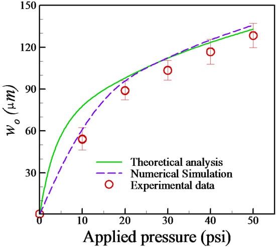
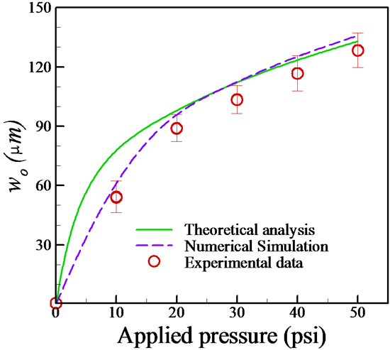
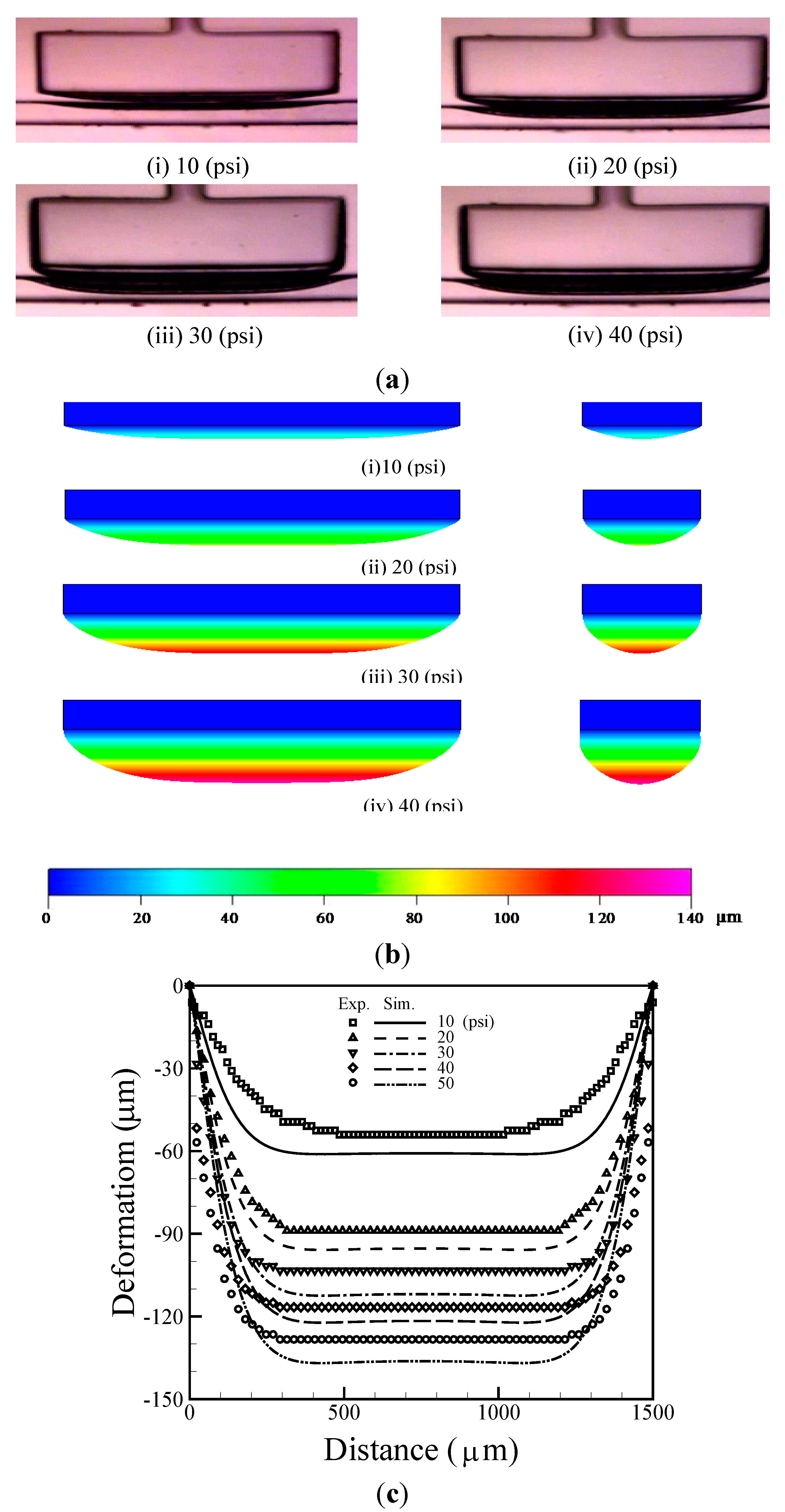
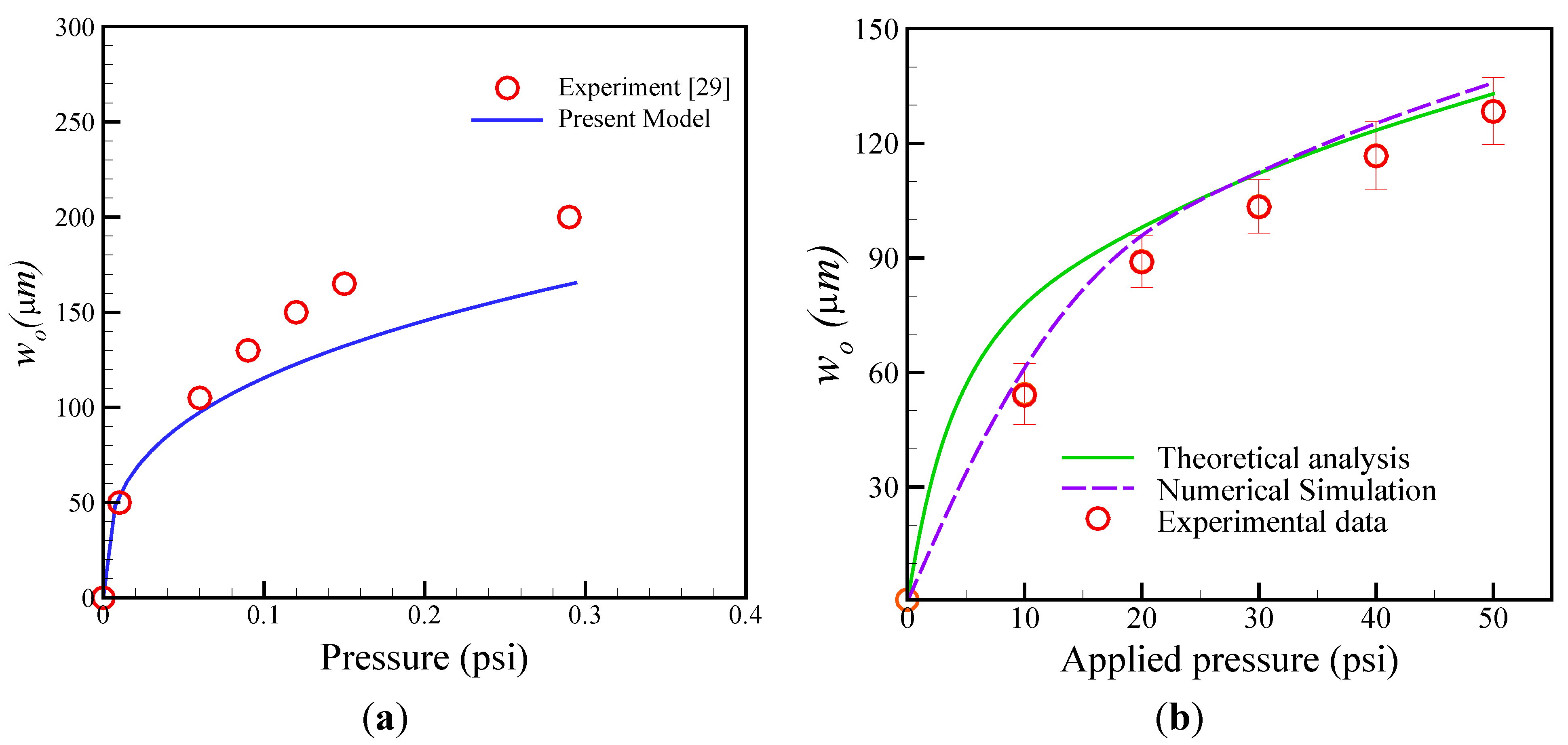
4.1. Estimation of Membrane Deformation

Figure 5a shows the deformation of the flexible membrane under applied air pressures of 10, 20, 30 and 40 psi. As expected, the maximum deformation increases with increases in applied pressure. The experimental results show that increasing applied pressure increases the deformation of the flexible membrane structure and results in an increase in the stroke volume. In addition, experimental observation shows that the fluid flow was difficult to interrupt while the membrane is completely deflected down to another side at a pressure of 40 psi or even higher. Therefore, high pressure applied in the microvalves is unable to shut the fluid flow in the single mode. This results in fluid back flow that causes potential sample contamination. The deformation of the flexible membrane structure was numerically investigated under different operating pressures as shown in Figure 5b. The numerical representation of the deformation contours of x-z cross-sectional and y-z cross-sectional surfaces are shown under the air pressures of 10, 20, 30, and 40 psi, respectively. As was observed in experiments, the numerical deformation profiles of x-z plane (longer side) also exhibit two segments: Flat-shaped and curve-shaped profiles. Contrarily, the deformation of y-z plane (shorter side) demonstrated a symmetric curve-shaped profile. Figure 5c shows the deformation profiles for the numerical calculation and experimental data. The comparison results show that the flexible membrane deformation profiles obtained by numerical calculations generally agree with the measurement data, although the deformations obtained by numerical calculations are larger than that of the experimental ones in the flat-shaped profile. Notably, the curved-shaped profiles occur within 300 μm from the edges. In contrast, the distance calculated in theoretical mode is about 329 μm. Figure 6 shows the numerical deformations of the x-directional and y-directional displacements under the pressure of 50 psi. The x- and y-directional displacements of PDMS membranes are limited to about 8 μm and 0.1 μm, respectively. The results demonstrate the x- and y-directional displacements are much less than the z-directional displacement. Therefore, these results verify the assumptions in the theoretical analysis, i.e., the x- and y-direction displacements are much shorter than the z-direction displacement.
Figure 7a shows the present analytical model (Equation (12)) compared with the experimental measurements [29]. The results demonstrated that the prediction of the present model is slightly lower than that of experimental data. However, the trend of the calculations are reasonable in agreement with experimental observations. The maximum deviations of the results are about 17.5%. Figure 7b compares the relationship between maximum deformation and applied pressures according to the theoretical analysis, numerical calculations and experimental measurements. The theoretical and numerical models are reasonably consistent with the experimental measurements. The numerical results are more precise than the theoretical analysis results, however, the numerical model requires longer time to calculate membrane deformation by using FEM method. Figure 7 also shows that maximum deformations are clearly divided into two regions: A small deformation region (implied that maximum deformations less than the membrane thickness, i.e., wo < h) described by the linear relationship, and a larger deformation region (implied that maximum deformations larger than the membrane thickness, i.e., wo > h) described by the non-linear relationship. The PDMS membranes are affected by the elasticity properties in the smaller deformation, but exhibit plasticity properties in the larger deformation. If a flexible membrane is working under a high applied pressure that results in large deformation, the membrane will be elastically fatigued, and the lifetime will also be reduced.
Figure 5. (a) Experimental and (b) numerical deformation of the flexible membrane structure (c) comparison of numerical calculations and experimental measurements at various air pressures.
Micromachines 06 00216 g005
Figure 6. Numerical deformations of (a) the x-directional; and (b) y-directional displacements at 50 psi.
Micromachines 06 00216 g006
Figure 7. (a) Comparison of the present model and experimental data for maximum deformation; (b) Comparison of theoretical analysis, numerical simulation and measured data for maximum deformation of membrane at various air pressures.
Micromachines 06 00216 g007

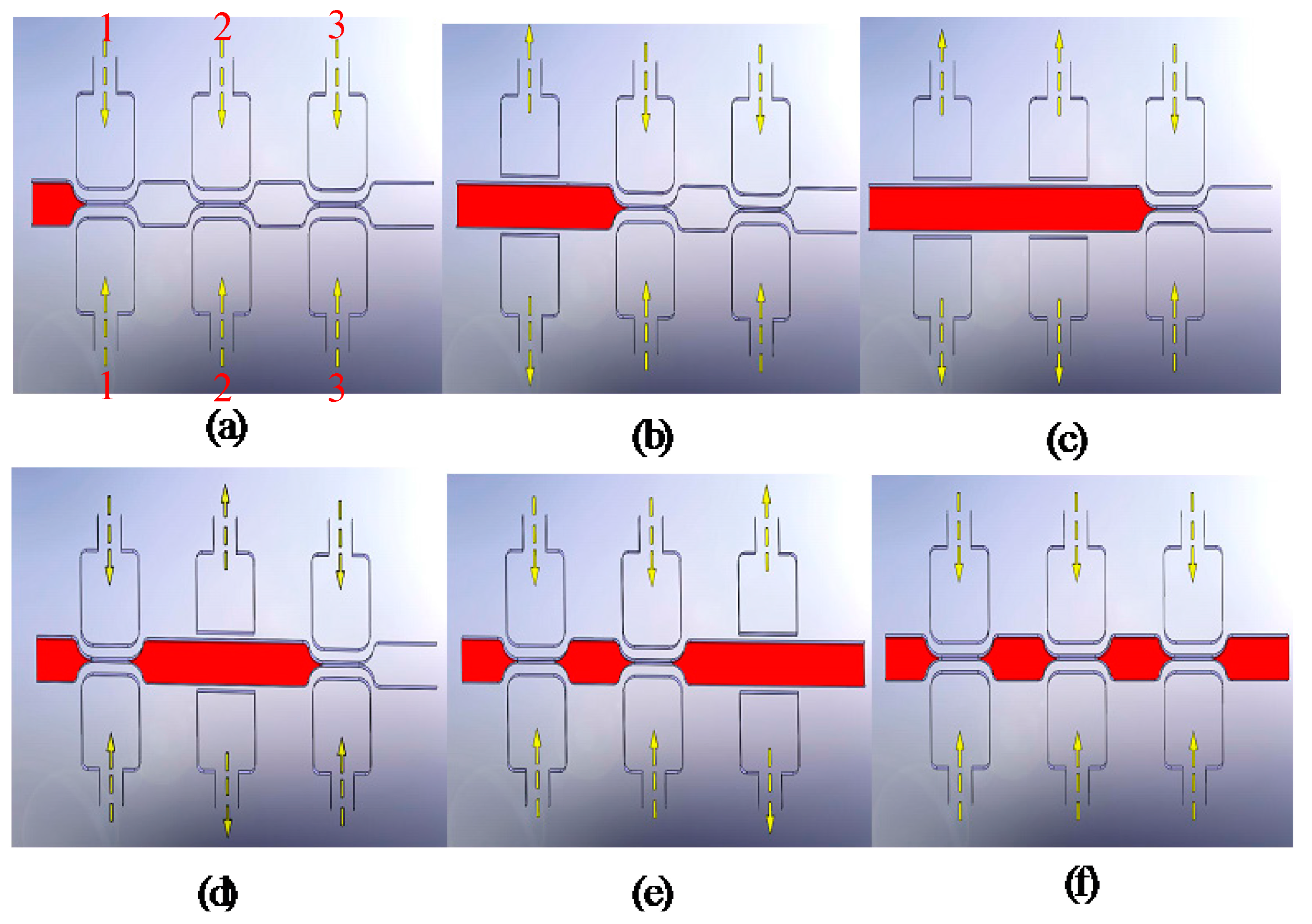
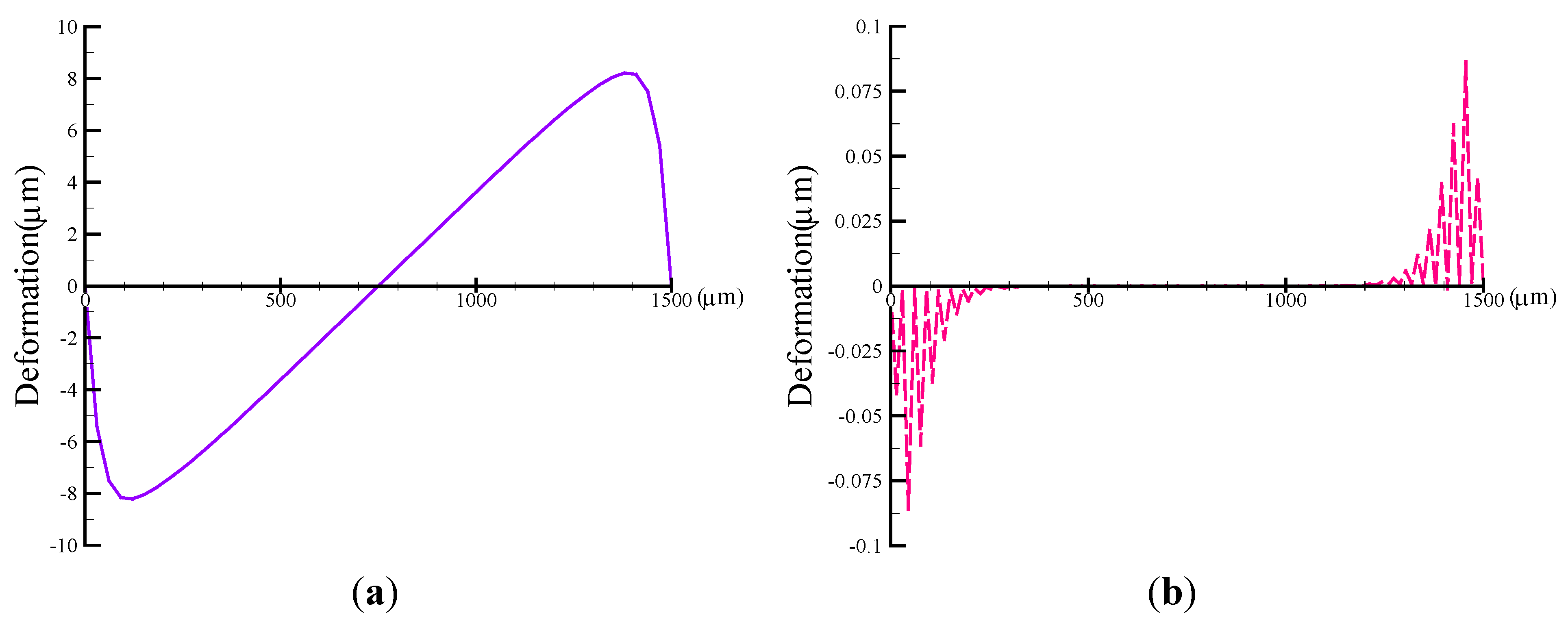
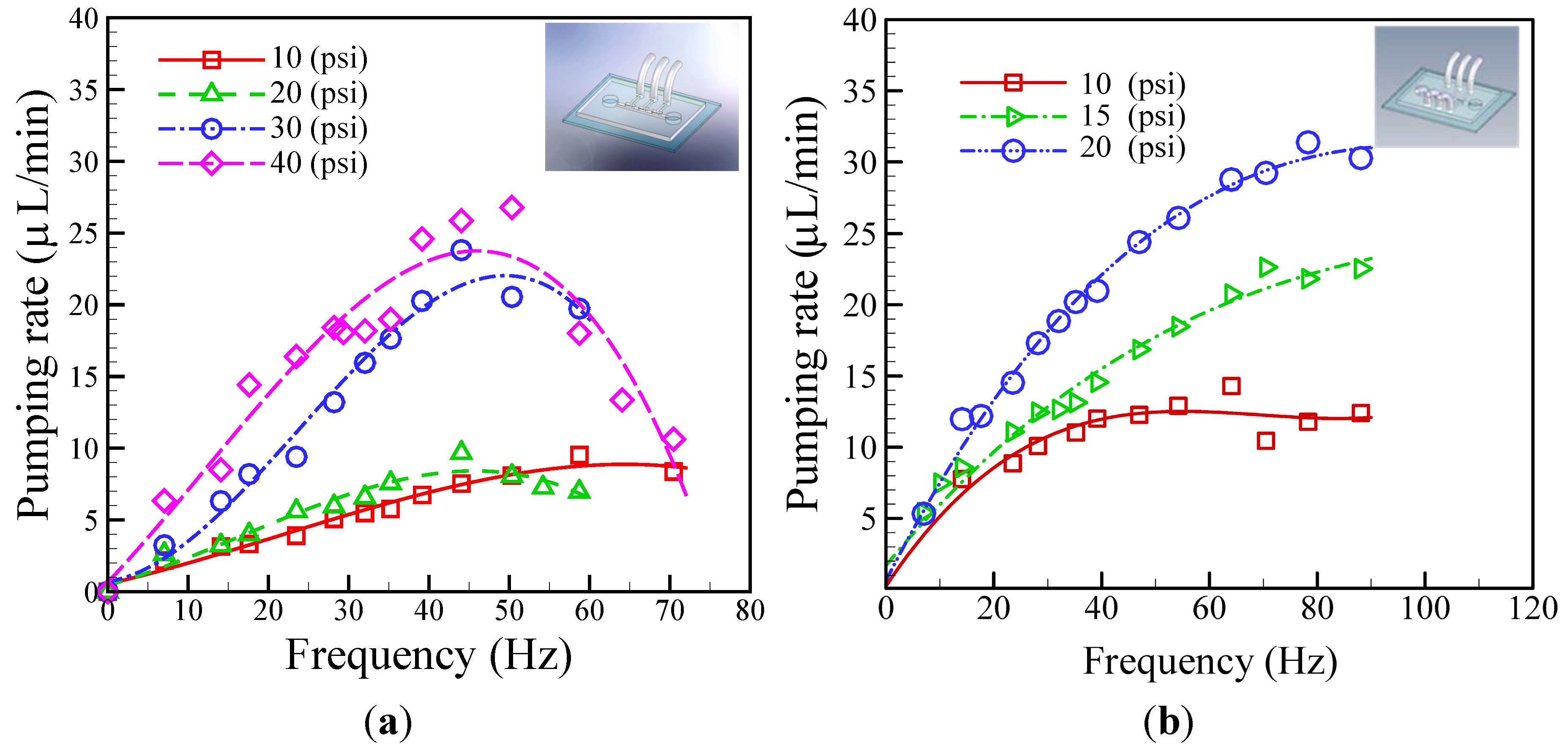
4.2. Evaluation of Pumping Rate

The volumetric flow rate in the proposed medium pumping scheme is determined predominantly by the applied pneumatic pressure and its frequency. To establish a quantitative link between these parameters, the pumping rate was measured at various applied pneumatic pressures (10, 20, 30 and 40 psi) and frequencies (5–70 Hz). An observation in Figure 8a shows the liquid pumping rates correlate with pneumatic pressures. This phenomenon can be reasonably explained by the fact that the increased pneumatic pressure increases membrane deformation and forces liquids through the microchannel. Figure 8a also reveals that, under the experimental conditions investigated, the pumping rate performance shows a similar profile of an initial increase with an increase in applied frequency and then followed by a decline in the saturation flow rate when frequency reached 45–50 Hz. The decline in the liquid pumping rate observed in the investigations results mainly from the lagging mechanical response of PDMS membranes at high frequencies. This phenomenon has also been reported previously. The lag results from the longer time needed to re-actuate the flexible membranes and the time needed to switch on/off the EMVs. Because the membranes do not have enough time to reopen completely, less fluid passes through. Within the experimental conditions explored, 40 psi pneumatic pressure, which obtained the best liquid pumping performance, provided a maximum flow rate approximating 28.0 µL·min−1. To minimize the lagging response and the fluid backflow effect, performance was measured in double-side actuation mode (Figure 8b). The performance tests showed that, at lower operation frequencies (<50 Hz), pumping behavior resembled that in the single-side actuation mode. The flow rates correlated positively with the applied pressure and the operated frequency. However, no declines occurred at higher frequencies. The reason is that because of its shorter deflection distance, the PDMS membrane does not activate the lagging response mechanism. Notably, compared to the single-side actuation mode, the double-side mode can afford maximum pumping rate of 30.0 μL/min at 20 psi that is half of the total pressure energy (40 psi) required in the single-side mode to attain similar pumping rate (28.0 µL·min−1). Most importantly, the design of the double-side actuated mode can prevent the backflow of the fluids particular to microfluidic cell culture systems. In conclusion, the double-side actuated mode not only enhances pumping performance, it also decreases a hysteresis effect on the membrane.
Figure 8. Relationship between the pumping rate and the driving frequencies at various operating air pressures. (a) the single-side; and (b) double-side actuated mode micropumps.
Micromachines 06 00216 g008

5. Conclusions

In this paper, we derived a theoretical model that can describe the deformation behavior of a PDMS membrane in a microfluidic micropump. With this theoretical model, numerical simulations are able to predict larger deformation mechanisms. The results of theoretical and numerical calculations are in reasonable agreements with the experimental results for the deformation of PDMS membrane. The theoretical and numerical results were used to facilitate optimum design of the actuated membrane of the proposed micropump. Performance tests to evaluate pumping efficiency also showed that the double-side actuated mode not only reduces the required applied pressure, it also avoids the lagging response effect of the PDMS membrane and prevents the backflow of fluids. Pumping rates observed in the performance tests reached as high as 30.0 μL/min. The integration of these newly designed micropumps can accelerate the development of miniaturized systems and fully-automated microfluidic systems.

Acknowledgments

The authors would like to thank the National Science Council of the Republic of China, Taiwan for financially/partially supporting this research under NSC102-2221-E-214-031 and ISU100-INT-09.

Author Contributions

Tai-Yen Yeh and Jr-Lung Lin conceived and designed the experiments; Tai-Yen Yeh and Chi-Han Chiou performed the experiments; Jr-Lung Lin analyzed the data; Chi-Han Chiou contributed reagents/materials/analysis tools; Jr-Lung Lin wrote the paper.

Conflicts of Interest

The authors declare no conflict of interest.

References

  1. Laser, D.J.; Santiago, J.G. A review of micropumps. J. Micromech. Microeng. 2004, 14, R35–R64. [Google Scholar] [CrossRef]
  2. Fu, A.Y.; Chou, H.-P.; Spence, C.; Arnold, F.H.; Quake, S.R. An integrated microfabricated cell sorter. Anal. Chem. 2002, 74, 2451–2457. [Google Scholar] [CrossRef] [PubMed]
  3. Fu, A.Y.; Spence, C.; Scherer, A.; Arnold, F.H.; Quake, S.R. A microfabricated fluorescence-activated cell sorter. Nat. Biotechnol. 1999, 17, 1109–1111. [Google Scholar] [CrossRef] [PubMed]
  4. Maillefer, D.; Gamper, S.; Frehner, B.; Balmer, P. A high-performance silicon micropump for disposable drug delivery systems. In Proceedings of The 14th IEEE International Conference on Micro Electro Mechanical Systems, Interlaken, Switzerland, 25 January 2001; pp. 413–417.
  5. Hong, J.W.; Studer, V.; Hang, G.; Anderson, W.F.; Quake, S. A nanoliter-scale nucleic acid processor with parallel architecture. Nat. Biotechnol. 2004, 22, 435–439. [Google Scholar] [CrossRef] [PubMed]
  6. Liu, J.; Enzelberger, M.; Quake, S.R. A nanoliter rotary device for polymerase chain reaction. Electrophoresis 2002, 23, 1531–1536. [Google Scholar] [CrossRef] [PubMed]
  7. Bourouina, T.; Bosseboeuf, A.; Grandchamp, J.P. Design and simulation of an electrostatic micropump for drug-delivery applications. J. Micromech. Microeng. 1997, 7, 186–188. [Google Scholar] [CrossRef]
  8. Saif, M.T.A.; Alaca, B.E.; Sehitoglu, H. Analytical modeling of electrostatic membrane actuator for micro pumps. J. Microelectromech. Syst. 1999, 8, 335–345. [Google Scholar] [CrossRef]
  9. Francais, O.; Dufour, I.; Sarraute, E. Analytical static modeling and optimization of electrostatic micropumps. J. Micromech. Microeng. 1997, 7, 183–185. [Google Scholar] [CrossRef]
  10. Gong, Q.L.; Zhou, Z.Y.; Yang, Y.H.; Wang, X.H. Design, optimization and simulation on microelectromagnetic pump. Sens. Actuators A 2000, 83, 200–207. [Google Scholar] [CrossRef]
  11. Capanu, M.; Boyd, J.G.; Hesketh, P.J. Design, fabrication, and testing of a bistable electromagnetically actuated microvalve. J. Microelectromech. Syst. 2000, 9, 181–189. [Google Scholar] [CrossRef]
  12. Jeong, O.C.; Konishi, S. Fabrication and drive test of pneumatic PDMS micro pump. Sens. Actuators A 2007, 135, 849–856. [Google Scholar] [CrossRef]
  13. Unger, M.A.; Chou, H.-P.; Thorsen, T.; Scherer, A.; Quake, S.R. Monolithic microfabricated valves and pumps by multilayer soft lithography. Science 2000, 288, 113–116. [Google Scholar] [CrossRef] [PubMed]
  14. Thorsen, T.; Maerkl, S.J.; Quake, S.R. Microfluidic large-scale integration. Science 2002, 298, 580–584. [Google Scholar] [CrossRef] [PubMed]
  15. Chou, H.P.; Unger, M.A.; Quake, S.R. A microfabricated rotary pump. Biomed. Microdevice 2001, 3, 323–330. [Google Scholar] [CrossRef]
  16. Jeong, O.C.; Yang, S.S. Fabrication and test of a thermopneumatic micropump with a corrugated p+ diaphragm. Sens. Actuators A Phys. 2000, 83, 249–255. [Google Scholar] [CrossRef]
  17. Van de Pol, F.C.M.; van Lintel, H.T.G.; Elwenspoek, M.; Fluitman, J.H.J. Therpneumatic micropump based on microengineering techniques. Sens. Actuators A Phys. 1990, 21, 198–202. [Google Scholar] [CrossRef]
  18. Spencer, J.G. Piezoelectric micropump with three valves working peristaltically. Sens. Actuators A Phys. 1990, 21–23, 203–206. [Google Scholar] [CrossRef]
  19. Morris, C.J.; Forster, F.K. Optimization of a circular piezoelectric bimorph for a micropump driver. J. Micromech. Microeng. 2000, 10, 459–465. [Google Scholar] [CrossRef]
  20. Husband, B.; Bu, M.; Evans, A.G.R.; Melvin, T. Investigation for the operation of an integrated peristaltic micropump. J. Micromech. Microeng. 2004, 14, S64–S69. [Google Scholar] [CrossRef]
  21. Lin, Q.; Yang, B.; Xie, J.; Tai, Y.-C. Dynamic simulation of a peristaltic micropump considering coupled fluid flow and structural motion. J. Micromech. Microeng. 2007, 1, 220–228. [Google Scholar] [CrossRef]
  22. Wang, C.H.; Lee, G.B. Automatic bio-sampling chips integrated with micropumps and microvalves for multiple disease detection. Biosens. Bioelectron. 2005, 21, 419–425. [Google Scholar] [CrossRef] [PubMed]
  23. Tseng, H.Y.; Wang, C.H.; Lin, W.Y.; Lee, G.B. Membrane-activated microfluidic rotary devices for pumping and mixing. Biomed. Microdevices 2007, 9, 545–554. [Google Scholar] [CrossRef] [PubMed]
  24. Wang, C.H.; Lee, G.B. Pneumatically-driven peristaltic micropumps utilizing serpentine-shape channels. J. Micromech. Microeng. 2006, 16, 341–348. [Google Scholar] [CrossRef]
  25. Lin, J.L.; Wang, S.S.; Wu, M.H.; Oh-Yang, C.C. Development of an integrated microfluidic perfusion cell culture system for real-time microscopic observation of biological cells. Sensors 2011, 11, 395–411. [Google Scholar]
  26. Timoshenko, S.; Woinosky-Krieger, S. Theory of Plates and Shells, 2nd ed.; McGraw-hill: New York, NY, USA, 1959; pp. 415–420. [Google Scholar]
  27. Fan, B.; Song1, G.; Hussain, F. Simulation of a piezoelectrically actuated valveless micropump. Smart Mater. Struct. 2005, 14, 400–405. [Google Scholar] [CrossRef]
  28. Fuard, D.; Tzvetkova-Chevolleau, T.; Decossas, S.; Tracqui, P.; Schiavone, P. Optimization of poly-di-methyl-siloxane (PDMS) substrates for studying cellular adhesion and motility. Microelectron. Eng. 2008, 85, 1289–1293. [Google Scholar] [CrossRef]
  29. Sim, W.; Kim, B.; Choi, B.; Park, J.-O. Theoretical and experimental studies on the parylene diaphragms for microdevices. Microsyst. Technol. 2005, 11, 11–15. [Google Scholar] [CrossRef]

