Abstract
Medical microrobots have been widely used in clinical applications, particularly the spiral type locomotion mechanism, which was recently considered one of the main self-propelling mechanisms for the next medical microrobot to perform tasks such as capsule endoscopy and drug delivery. However, limits in clinical applications still exist. The spiral action of the microrobot while being used for diagnosis may lead to pain or even damage to the intestinal wall due to the exposed mechanisms. Therefore, a new locomotive mechanism, named the shrouded propeller mechanism, was proposed to achieve a high level of medical safety as well as effective propulsive performance in our study. The shrouded propeller mechanism consists of a bare spiral propeller and a non-rotating nozzle. To obtain a high effective propulsive performance, two types of screw grooves with different shapes including the cylindrical screw groove and the rectangular screw groove with different parameters were analyzed using the shrouded model. Two types of magnetic actuated microrobots with different driving modes, the electromagnetic (three-pole rotor) actuated microrobot and the permanent magnet (O-ring type magnet) actuated microrobot were designed to evaluate the performance of the electromagnetic actuation system. Based on experimental results, the propulsive force of the proposed magnetic actuated microrobot with a shrouded propeller was larger than the magnetic actuated microrobot with a bare spiral propeller under the same parameters. Additionally, the shrouded propeller mechanism as an actuator can be used for other medical microrobots for flexible locomotion.
1. Introduction
Swimming robots have great potential in industrial applications and medical applications [1,2,3,4,5,6,7,8,9]. In recent years, many kinds of microrobots have been developed to achieve various tasks due to technical advancements in manufacturing and further progress is expected in this field [10,11,12,13]. For instance, microrobots are commonly used in industry to repair and maintain pipelines [14,15,16,17,18,19,20,21,22]. The microrobot is also used in medicine to avoid unnecessary incisions during surgical operations [23,24]. Some researchers have proposed a kind of capsule endoscope, which is swallowed by the patient to diagnose the intestinal organs of the human body. However, this kind of robot is uncontrollable due to involuntary muscle movements known as peristalsis [25]. To solve this problem, many microrobots have been developed with traditional motors and smart materials as actuators [6,26,27,28,29]. These microrobots look perfect in theory and design, but are more or less ineffective. There are diagnostic problems due to the cable or wire and it is very difficult to reach a position accurately or operate in a very narrow and deep space. Therefore, a new driving mode of the microrobot has urgently been demanded in medical applications.
Recently, remote control of the magnetic actuated microrobot using a magnetic field has been popular and developed due to realize external wireless energy supply [12,26,30,31,32,33,34]. One of the microrobots is called a fish-like microrobot. It imitates the movement of a fish to produce a propulsive force with oscillatory motion or undulatory motion. The fish-like microrobot has one important limitation; it moves in only one direction inside a pipe. Therefore, another kind of proposed microrobot has been developed to solve this problem. This kind of microrobot can move with a spiral motion or a screw motion by using a bare spiral propeller [16]. Previously, we proposed a novel type of hybrid microrobot, with a spiral motion, a fin motion and a paddling motion [26]. The hybrid microrobot uses a hybrid locomotion scheme, consisting of three disparate actuation strategies: (1) using a spiral structure to generate a spiral propulsive force; (2) using a flexible tail to generate a fish-like propulsive force; (3) using a paddling leg to generate a paddle propulsive force. The microrobot achieved a basic forward motion in the horizontal plane. However, this kind of bare spiral propeller as a main actuator may cause pain and damage to the intestinal wall [35]. In other words, when the microrobot rotates inside the intestine, the intestinal wall may cause damage due to the rotating friction between the bare spiral propeller and the intestinal wall. Therefore, we proposed a conceptual hybrid microrobot to reduce patient pain and discomfort [32]. However, further clinical application is needed in order to produce a robot that is capable of treating disease, diagnosing intestinal problems and conducting minimal invasive surgery. As well, the robot needs to be able to install actuating elements (e.g., drug delivery mechanism), a camera (e.g., endoscope) and sensing elements for achieving medical tasks. Therefore, medical safety, loading abilities and an effective propulsive performance is extremely important and challenging. This paper presents a new locomotive mechanism, named the shrouded propeller mechanism to improve medical safety and propulsive performance. The robot is composed of a bare spiral propeller and a non-rotation nozzle. Two different types of screw grooves with different parameters are analyzed using the shrouded propeller model to obtain the optimal performance needed for clinical application. An electromagnetic actuator and a permanent magnetic actuator were assembled to evaluate their performance. In the future, the shrouded propeller mechanism as a driving unit can be used for medical robots, e.g., passive actuator robot, capsule endoscopies.
A shrouded propeller model is illustrated in Section 2. We assembled two type of robots with different actuators and illustrated their working principle in Section 3. Based on the working principle, we designed an electromagnetic actuation system for evaluating their performance in Section 4. Section 5 describes the experimental results and discussions with conclusions and future works in Section 6.
2. Modeling of the Magnetic Actuated Microrobot with Spiral Jet Motion
Several spiral or screw types of microrobots have recently been developed for achieving various functions [10,16,33,34,35]. However, their propulsive mechanisms are comprised of a bare propeller, which leads to a low propulsive force [17]. Thus, we proposed a novel propulsive mechanism for a magnetic actuated microrobot to increase the efficiency of the propulsive force. Figure 1 illustrates our proposed microrobot, which moves using a propulsion arrangement called a shrouded propeller. A shrouded propeller is a bare propeller fitted with a non-rotating nozzle, which is used to improve the efficiency of the propeller, especially on propellers with a limited diameter. The non-rotating nozzle connects to the propeller with an axis and bearing. When the propeller rotates to accompany the magnetic actuator, the shrouded propeller pushes the fluid backward generating a reaction force, which creates a forward motion, also called a spiral jet motion. In respect to hydrodynamics, the shrouded propeller produces a larger propulsive force than the bare propeller. For medicine, the shrouded propeller type of microrobot can reduce the damage caused to the intestinal wall due to the non-rotating nozzle thereby reducing pain for patients.
Figure 2 shows the propulsive force model of the shrouded propeller. When the microrobot moves inside the pipe, which is completely filled by the liquid, the liquid enters one end of the microrobot and leaves the other end of the microrobot at the same time. Since the liquid is incompressible, the volume of liquid through any perpendicular plane in any interval of time must be the same everywhere in the microrobot. Consider the inflow area and outflow area of the microrobot whose cross-sectional area are inflow area A1 and outflow area A2. The volume of liquid passing through the inflow area is equal to the volume of liquid passing through the outflow area for unit time, to give Equation (1):
where, Q is the flow of spiral jet motion, V1 is the inflow velocity of the area A1 and V2 is the outflow velocity of the area A2.
The propulsive force is defined by Equation (2):
where, Fp is the propulsive force, ρ is the density of liquid.
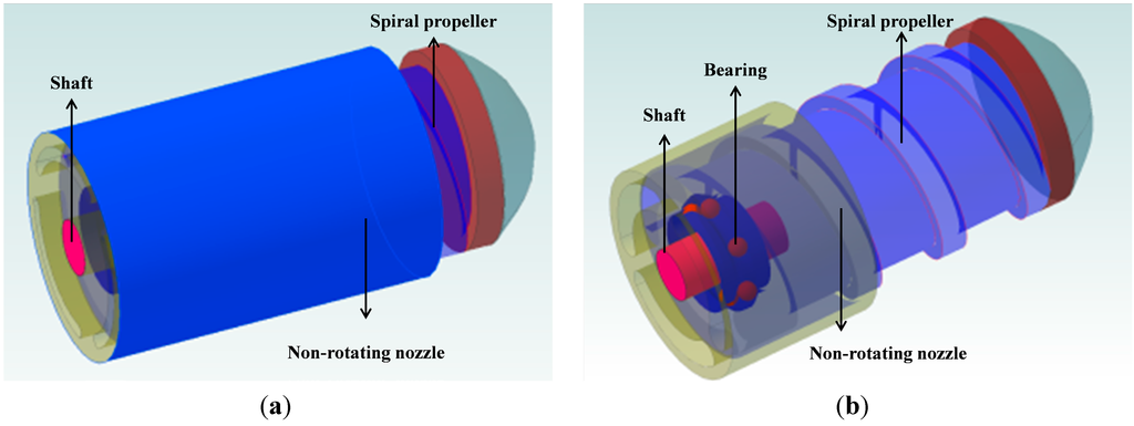
Figure 1.
Conceptual design of the microrobot with shrouded propeller (a) overall view; (b) perspective view.
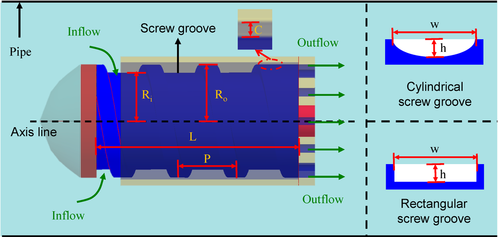
Figure 2.
Propulsive force model.
The propulsive performance of a hydrodynamic shrouded propeller is determined, to a large extent, by the flow of fluid Q. The Q is usually determined by two parameters: external parameters and internal parameters. The external parameters usually include the length of the microrobot L, and the interval between the spiral propeller and non-rotating nozzle C [36]. In this paper, these external parameters are taken as fixed. The following internal parameters (e.g., Qcyc, n, ω) should be considered in order to obtain a high propulsive force. Qcyc means the flow of one cycle of the screw depends on the outer radius Ro and inner radius Ri, as shown in Figure 2, n is the screw numbers which is equal to L/P, where P is the pitch of one screw. While the rotational speed is N, the propulsive force is defined by Equation (3):
If the angle of the angular speed of the microrobot is ω, we have:
According to the above discussion, we designed two types of screw grooves, a cylindrical screw groove and a rectangular screw groove, with different parameters Qcyc to evaluate the performance of the microrobot. Here, we assumed the dimensions to be Ro = 6.5 mm for the outer radius, Ri = 5.5 mm for the inner radius, and L = 30 mm for the length respectively. If the microrobot generated a propulsive force Fp = 10 mN, the cylindrical screw groove type with h = 1 mm and w = 2 mm needed a rotational speed of N = 130 rad/s, whereas, the rectangular screw groove type with h = 1 mm and w = 2 mm, needed a rotational speed of N = 102 rad/s. It meant that the rectangular screw groove type microrobot needs a lower rotational speed than the cylindrical screw groove type microrobot in order to generate the same propulsive force. In other words, the rectangular screw groove type microrobot generated a larger propulsive force than the cylindrical screw groove type microrobot at the same rotational speed. The simulation results with different parameters are shown in Figure 3. This model would also allow the prediction of swimming performance as the overall dimensions scale down.
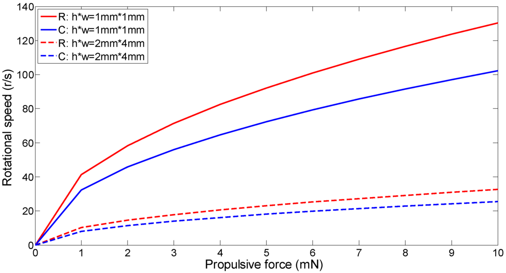
Figure 3.
Simulation results with different parameters, R means rectangular screw groove, C means cylindrical screw groove.
3. Magnetic Actuated Microrobot with Spiral Jet Motion
Based on the shrouded model, the rectangular screw groove is used to assemble the magnetic actuated microrobot. We designed two types of microrobots with different driving modes: an electromagnetic actuated microrobot and a permanent magnetic actuated microrobot. Additionally, we illustrated the working principle of both types.
3.1. Electromagnet Actuated Microrobot
Figure 4a shows the structure of an electromagnetic actuated microrobot. Its actuated part is mainly composed of a three-pole rotor with three windings of wire wrapped with a 120° phase difference, a brush, which is connected to the source of electrical energy, and a battery to supply the electrical energy. Its working principle is illustrated in Figure 4b. The electromagnetic actuated microrobot relies on the principle that likes magnetic poles repel and unlike magnetic poles attract each other. When an electric current is passed through a pole rotor, it generates an electromagnetic field aligned with the center of the coil. By switching the current on or off in a coil, its magnetic field can be switched on or off. When the electromagnetic actuated microrobot is placed inside a static magnetic field generated by a Helmholtz coil, a rotating magnetic field can be created by changing the sequence of the three-pole rotor on or off. These rotating magnetic fields interact with the external magnetic fields of the Helmholtz coils to create a magnetic moment on the three-pole rotor. The spiral structure, which connects the three-pole rotor with a shaft and bearing, rotates to create a propulsive force in the water, synchronously. By adjusting the strength of the external magnetic field, speed of the internal actuated microrobot can be controlled.
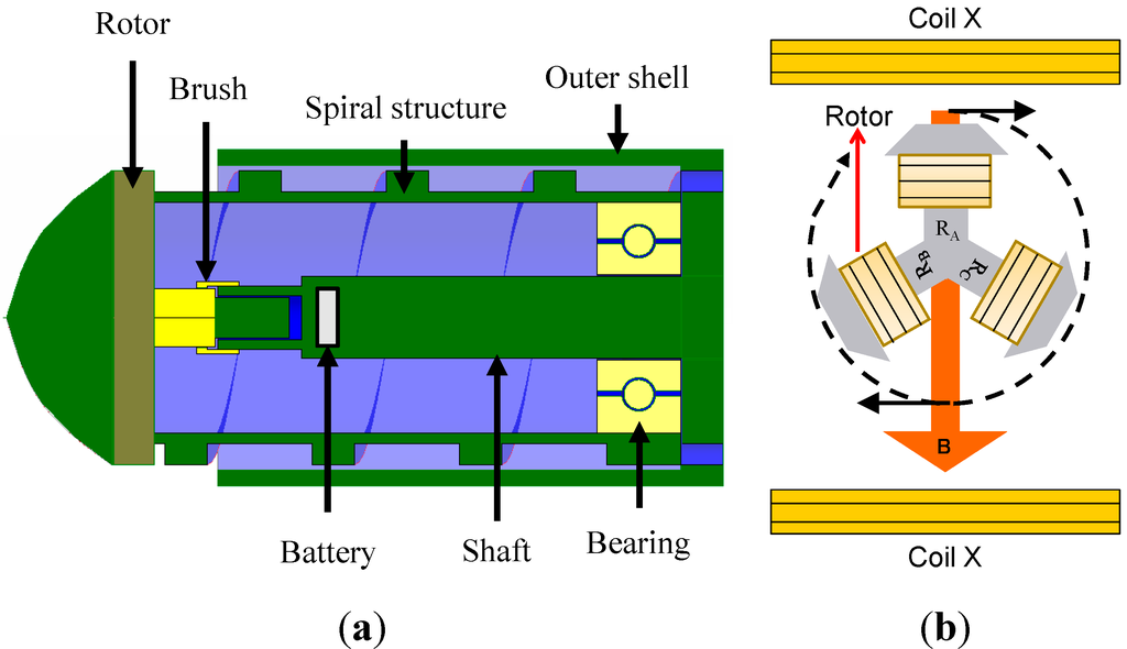
Figure 4.
Electromagnet actuated microrobot. (a) Structure of the microrobot; (b) Working principle.
3.2. Permanent Magnet Actuated Microrobot
Figure 5a shows the structure of a permanent magnetic actuated microrobot. Its actuated part is mainly composed of four permanent magnets as an actuator. Its working principle is illustrated in Figure 5b. According to magnetic theory, a magnetic moment is generated as a magnet’s dipole attempts to align with the local magnetic field. Thus, four neodymium permanent magnets are symmetrically placed inside the microrobot. When the Helmholtz coil generates an external rotating magnetic field, the four permanent magnets as a whole rotate along the rotational direction of the magnetic field due to the magnetic moment. The spiral structure, which connects the four permanent magnets with a shaft and bearing, rotates to create a propulsive force in the water, synchronously. By adjusting the rotational frequency of the magnetic field, the speed of the permanent magnetic actuated microrobot can be controlled.
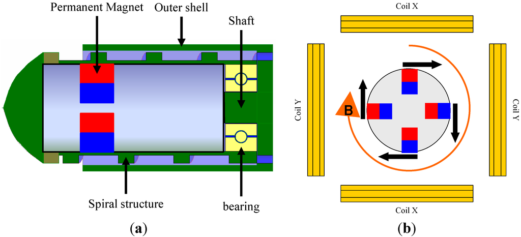
Figure 5.
Permanent magnet actuated microrobot. (a) Structure of the microrobot; (b) Working principle.
3.3. Fabrication of the Microrobot
The magnetic actuated microrobot with a shrouded propeller was assembled to text its performance and validate the driving model. The prototype of the electromagnetic actuated microrobot and the permanent magnet actuated microrobot are shown in Figure 6a,b, respectively. The bare spiral propeller and a non-rotating nozzle are made of polystyrene. Both the bare spiral propeller and the non-rotating nozzle are made of polystyrene. The diameter of the propeller is 12 mm and the length is 30 mm. The non-rotating nozzle is a hollow cylinder with a diameter of 14 mm and a length of 27 mm. To reduce the weight of the microrobot, we used an O-ring type magnet (Φ5 mm × Φ9.5 mm × 4 mm) instead of the four permanent magnets, as shown in Figure 6e. An external power supply was used to supply the electrical energy instead of a battery in the experiments. The specifications of the magnetic actuated microrobot are given in Table 1.
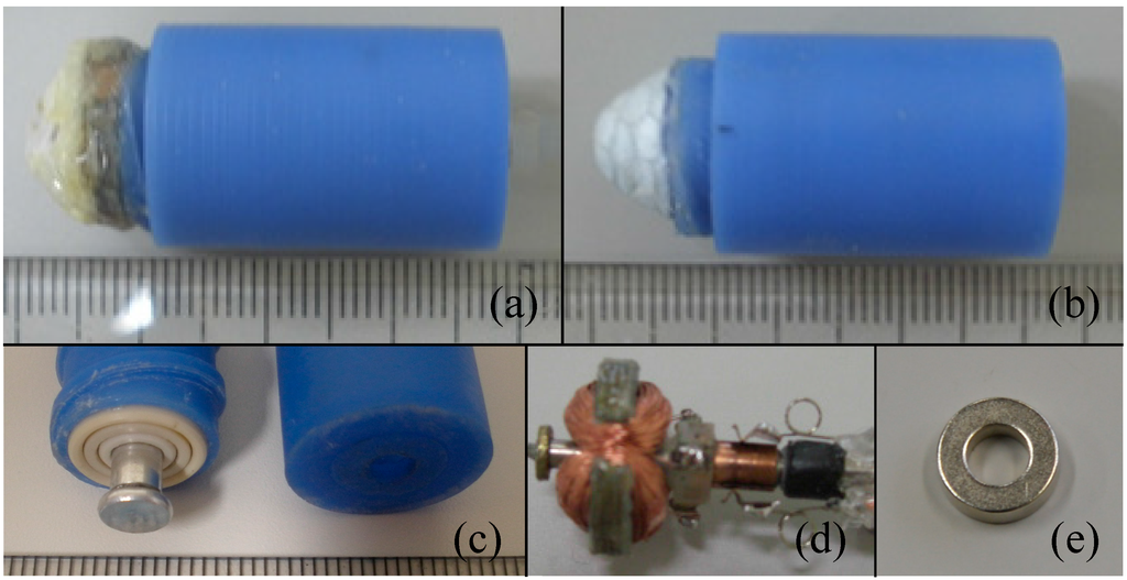
Figure 6.
Prototype of the magnetic actuated microrobot with spiral jet motion. (a) Electromagnet actuated microrobot; (b) Permanent magnetic actuated microrobot; (c) Bottom view of the microrobot composed of a bare propeller and a non-rotating nozzle; (d) Three-pole rotor as an actuator; (e) O-ring type magnet as a actuator.

Table 1.
Specifications of magnetic actuated microrobot.
| Microrobot | Electromagnet Actuated Microrobot | Permanent Magnetic Actuated Microrobot |
|---|---|---|
| Size | Φ14 mm × 37 mm | Φ14 mm × 37 mm |
| Actuator | Three-pole rotor | O-ring type magnet |
| Current | 0.25A | - |
| Magnet | - | Φ5 mm × Φ9.5 mm × 4 mm with 1250 mT |
4. Electromagnetic Actuation System
As mentioned above, the magnetic actuated microrobot is driven by a magnetic field. In previous researches, various types of electromagnetic actuation systems have been developed to manipulate the magnetic microrobot in the organs, e.g., intestinal tract, blood vessels [9,35]. Due to the structure of the electromagnetic actuation system, the locomotive range of the microrobot is limited [26]. Therefore, we proposed a novel electromagnetic actuation system, which has teleoperation control in real-time for medical applications. Figure 7 shows the whole electromagnetic actuation system. On the master side, a visual image inside a pipe is monitored by a camera and displayed on a monitor. Using a Phantom Omni device, control instructions are sent out and transmitted to a control unit, which of an amplifier, a DC power supply and a control circuit. Upon receiving instructions, the slave mechanisms (3-axis Helmholtz coils) generate an external magnetic field to control the movement of the magnetic actuated microrobot. The monitor can also display the data calculated from the magnetic sensor array for obtaining the real-time position of the robot. The positioning system is used to accomplish a close-loop control and ensure the robot achieves the task. Consequently, the doctor appears to accurately control the position and posture of the wireless microrobot in the human body [32].
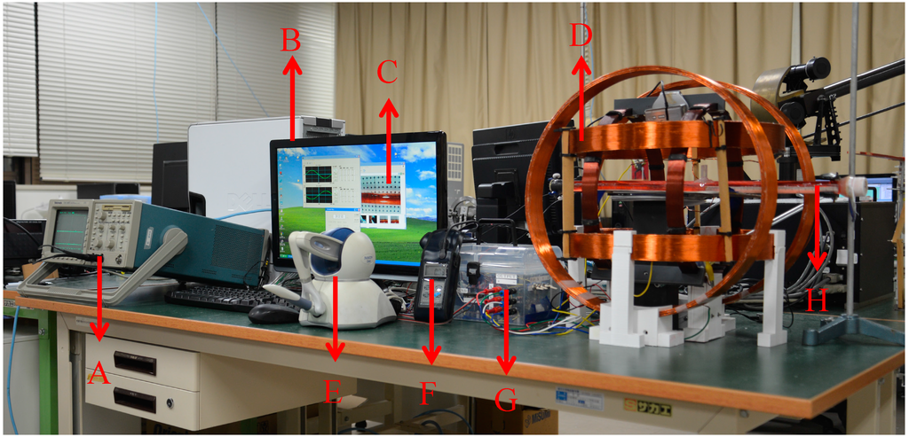
Figure 7.
Electromagnetic actuation system. A: Oscilloscope; B: PC; C: Visual images; D: 3-axis Helmholtz coils; E: Phantom Omni device; F: Magnetic sensor; G: Control unit; H: Pipe.
To evaluate the performance of the proposed two type microrobots, we used two types Helmholtz coils, Helmholtz coils with an iron core and Helmholtz coils without an iron core, to control the microrobot movement in the water. The reason is explained in Section 4.2. In order to optimize the design of both coils, we analyzed the performance of the Helmholtz coils using FEM methods by electromagnetic simulation software, PHOTO-Series version 7.1 (Photon, Kyoto, Japan). Based on the simulation results, we assembled and evaluated the performance of Helmholtz coils, which is described in detail in Section 5.1.
4.1. Helmholtz Coil without Iron Core
The Helmholtz coils without an iron core, which is also called a 3-axis Helmholtz coil, was developed to generate the rotational magnetic field to control the external magnetic field. The 3-axis Helmholtz coil is composed of three mutually orthogonal single-Helmholtz coils, which are called the X-Helmholtz coil (Diameter: 284 mm, Resistance: 2.4 Ω, Turns: 125), the Y-Helmholtz coil (Diameter: 350 mm, Resistance: 3.3 Ω, Turns: 150) and the Z-Helmholtz coil (Diameter: 400 mm, Resistance: 4.5 Ω, Turns: 180).
Each of the single-Helmholtz coils are composed of two identical circular coils which are placed symmetrically along a common axis, and separated by a distance L equal to the radius R of the coil. Electrical current flows in the same direction in each coil. The electrical current is a variable in the coil, and the relationship between magnetic flux density and electrical current is defined by Equation (5):
where, B is the magnetic flux density, at any point on the axis of the Helmholtz coils. R is the radius of the coil. μ0 is permeability of vacuum. N is the number of turns of coil and I is the electrical current of coil.
By adjusting the control signals of the 3-axis Helmholtz coils, a rotational or undulation magnetic field is generated to control the permanent magnet actuated microrobot in any direction.
4.2. Helmholtz Coil with Iron Core
The safety is very important in applications. When the Helmholtz coils without an iron core is used to control the electromagnet actuated microrobot, the range of electrical current is changed from 14 to 142 A. This value of electrical current is dangerous for human beings. Therefore, we fabricated the Helmholtz coils with an iron core. Each of the Helmholtz coils consists of a coil and an iron core. The iron core is used to increase the magnetic flux density in the working space, which is made of SS400. The magnetic flux density is adjusted by Equation (6):
where, B is the magnetic flux density of Helmholtz coils with iron core, N is the number of turns of Helmholtz coils with iron core, I is the electrical current of Helmholtz coils with iron core.
5. Experiments and Results
5.1. Measurement of the Magnetic Flux Density
The main goal in the design of the Helmholtz coils is to supply the magnetic field for controlling the magnetic actuated microrobot in the working space. We designed a system to measure the magnetic flux density and the schematic diagram is shown in Figure 8. The electrical currents of the Helmholtz coils were supplied by power suppliers, which were controlled by the control unit with a Digital Signal Processor. The Gauss meter (TM701, KANETEC, Nagano, Japan) was used to measure the magnetic field between the Helmholtz coils. The magnetic field can be measured in the range of 0 to 3000 mT with 0.01 mT resolution. Figure 9a shows the relationship between the electric current of the Helmholtz coils without an iron core and the working space of the magnetic flux density. Figure 9b shows the relationship between the electric current of the Helmholtz coils with an iron core and the working space of the magnetic flux density. The working space of measured magnetic flux density is very close to our simulated results. The magnetic flux density, along the X-axis of the working space, is symmetric about the center [37] and the magnetic field decreased from the center to the outer edge.
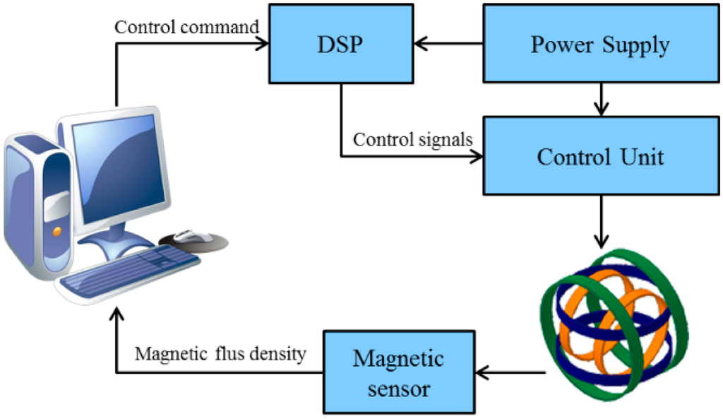
Figure 8.
Schematic diagram of the measurement system.
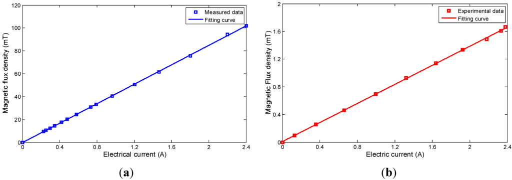
Figure 9.
Magnetic flux density of Helmholtz coils. (a) Helmholtz coil with iron core; (b) Helmholtz coil without iron core.
5.2. Measurement of the Rotational Speed of the Magnetic Actuated Microrobot
A measured system of rotational speed, as represented in Figure 10, was set up to measure the rotational speed of the magnetic actuated microrobot. The magnetic actuated microrobot was placed under water inside a tank by the two clamps. Firstly, the laser sensor (KEYENCE LB-1000, Keyence, Osaka, Japan) measured the displacement L1 with time T1. Secondly, adjusting the rotational speed of the magnetic actuated microrobot, when the displacement L2 with T2 was equal to the displacement L1 with T1, the magnetic actuated microrobot rotated in a circle. The experiments were repeated over ten times. The rotational speed was measured, as shown in Figure 11. The rotational speed of the electromagnetic actuated microrobot was adjusted by changing the external magnetic flux density until a maximum rotational speed was obtained; the rotational speed of the permanent magnet actuated microrobot was adjusted by changing the frequency of the external magnetic field until the maximum rotational speed was obtained.
As already mentioned, we compared the performance of two types of magnetic actuated microrobots, an electromagnetic actuated microrobot and a permanent magnetic actuated microrobot. The results of the different driving modes, a static magnetic field generated by Helmholtz coils with an iron core and a rotating magnetic field generated by Helmholtz coils without an iron core are given in Table 2.
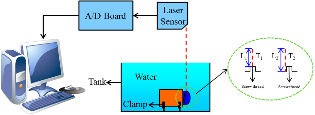
Figure 10.
Schematic diagram for measuring the rotational speed.
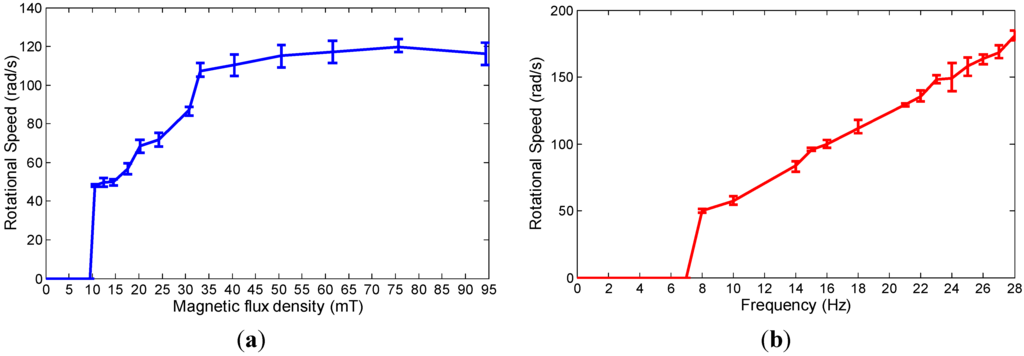
Figure 11.
Measurement results of the rotational speed of the magnetic actuated microrobot. (a) Rotational speed of the electromagnet actuated microrobot; (b) Rotational speed of the permanent magnet actuated microrobot.
Table 2.
Performance of magnetic actuated microrobot.
| Microrobot | Electromagnet Actuated Microrobot | Permanent Magnetic Actuated Microrobot |
|---|---|---|
| Actuator | Three-pole rotor | O-ring type magnet |
| Driving mode | Static magnetic field | Rotating magnetic field |
| Helmholtz coils | Helmholtz coil with iron core | Helmholtz coil without iron core |
| Speed control | Adjusting the strength of magnetic field | Adjusting the changing frequency of magnetic field |
5.3. Measurement of Propulsive Force of the Magnetic Actuated Microrobot
The measured experimental system was used to measure the propulsive force of the magnetic actuated microrobot in the water, as shown in Figure 12. Measured experiments of the propulsive force are divided to two steps. Firstly, a calibration test is necessary to confirm the deformation of the copper beam in order to maintain an effective deformation range and calculate the calibration of the relationship between the propulsive force and the bending displacement of the copper beam. Secondly, the rotational speed of the magnetic actuated microrobot is controlled by adjusting the frequency of the electric current. The displacement of the copper beam was obtained using a laser displacement sensor (KEYENCE LB-1000), and the propulsive force of the magnetic actuated microrobot was calculated using Equation (7), which is given by Fu et al. [32].
where, F is propulsive force, x is the displacement of the copper beam.
The measured result of the propulsive force is shown in Figure 13. The experimental results indicated that the propulsive force of the magnetic actuated microrobot with a non-rotating nozzle was larger than the magnetic actuated microrobot without a non-rotation nozzle with the same condition. Loss of some energy is converted into thermal energy due to external force, such as, the drag force of the water and viscous drag. The growth rates of the propulsive force are shown in Figure 14. From the experimental results, we know that the shrouded propeller mechanism has the capability to increase the performance of the propulsive force and is given by:
where, η is growth rates of the propulsive force, V1 is the speed of microrobot without a non-rotating nozzle and V2 is the speed of microrobot with non-rotating nozzle.
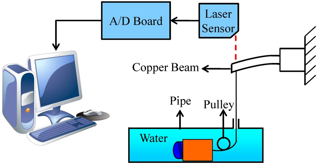
Figure 12.
Schematic diagram of the measured propulsive force.
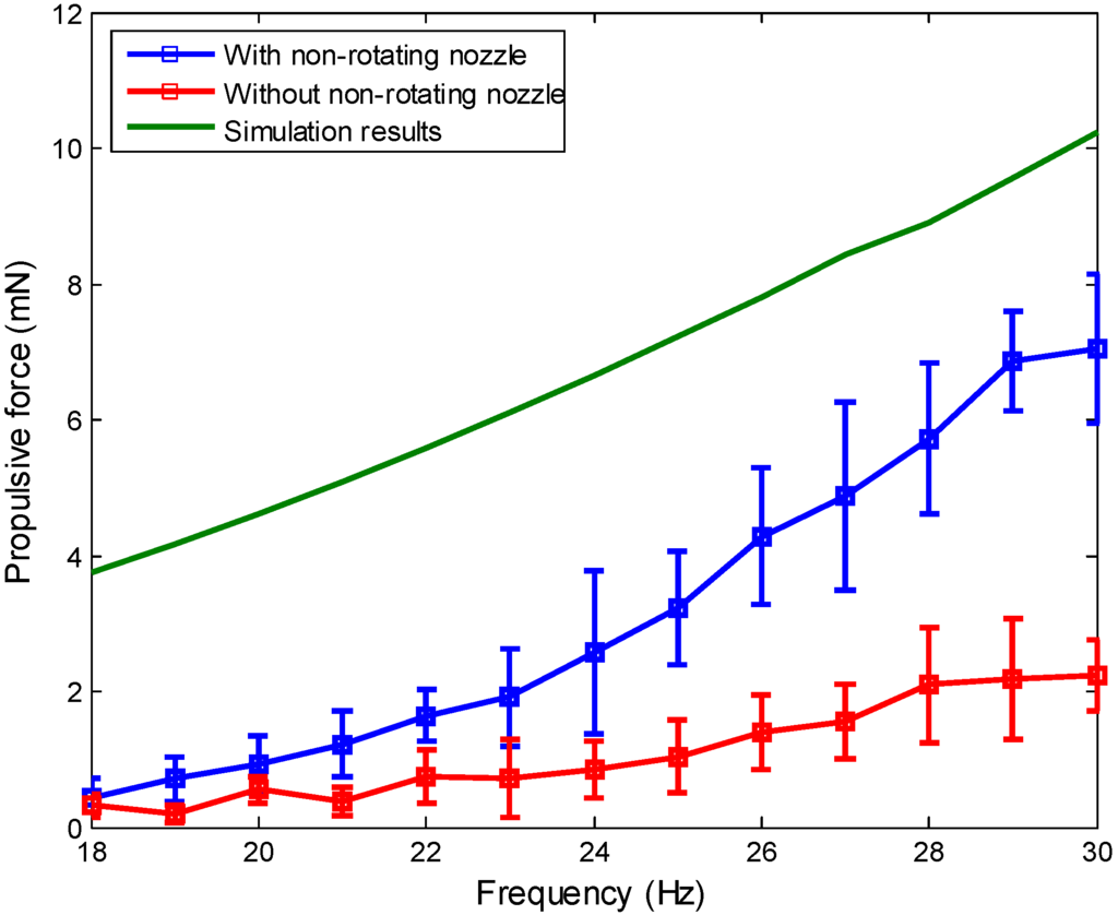
Figure 13.
Measured results of the propulsive force.
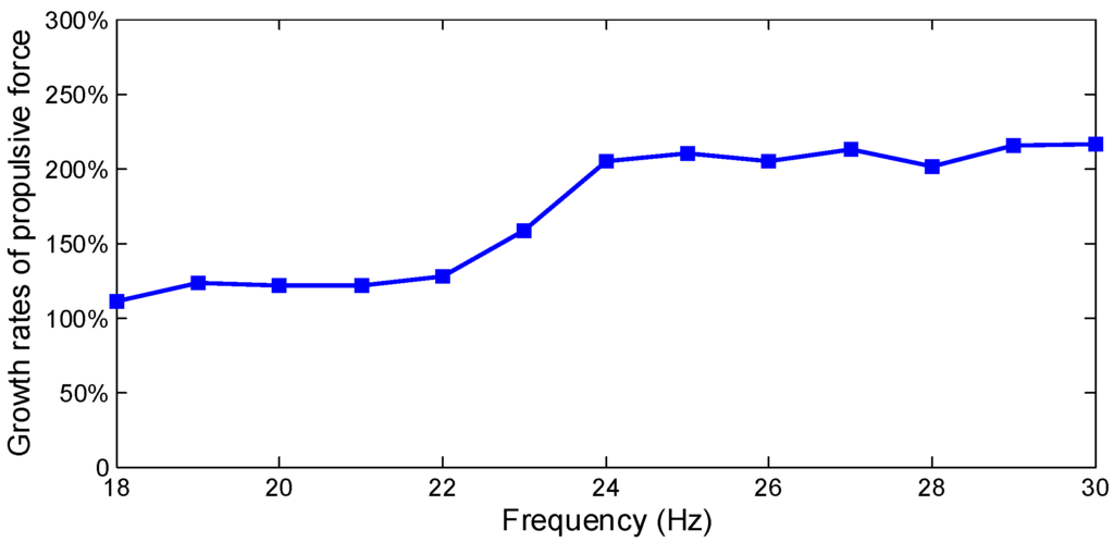
Figure 14.
Growth rates of propulsive force.
5.4. Results and Discussions
In general, a medical microrobot, which consists of a control module, power module, communicating module and a function module, is used to treat disease, diagnose intestinal problems and conduct minimal invasive surgery for clinical applications. Flexible locomotion is a key factor for the medical microrobot, which can represent the performance of microrobots. According to the controllability of the movement mechanism, medical microrobots can be split into two types: a passive locomotion type and an active locomotion type. The passive locomotion type medical microrobot has been applied in clinical diagnosis, such as M2A, PillCam®SB, and Norika3®. However, their movement direction is only a single forward motion because their movement depends on intestinal peristalsis. Some active locomotion type microrobot can achieve a backward motion or a stop motion in the intestine, but their movement area is limited due to cables. Nevertheless, the spiral type microrobot perhaps leads to less damage to the intestinal wall, thereby reducing the pain felt by patients. Based on the above performance comparisons, the shrouded propeller type microrobot is becoming the future development trend for medical microrobots by means of their comprehensive advantages, flexibilities and safety.
6. Conclusions
In this paper, we proposed a novel propulsive mechanism using a shrouded propeller composed of a bare propeller and a non-rotating nozzle for a microrobot, which is capable of increasing propulsion in water. Since there is a non-rotating nozzle, which covers the bare propeller, it may reduce the damage or harm to organs (e.g., intestinal wall, blood vessels) during medical procedures and be less painful for patients. We built a shrouded propeller model and discussed the relationship between the propulsive force and the shape of shrouded propeller with different parameters. With the shrouded propeller model, it was demonstrated that the rectangular screw groove generated more propulsive force than the cylindrical screw groove under the same conditions (e.g., screw thread turns n, screw groove width w and screw groove high h). We also designed two types driving modes for the microrobot according to the shrouded propeller model: the electromagnetic actuated microrobot and the permanent magnetic actuated microrobot. Finally, we evaluated the performance of both types of magnetic actuated microrobots using the electromagnetic system. The experimental results indicate:
- The electromagnetic actuated microrobot is driven by a static magnetic field generated by a Helmholtz coil with an iron core. By adjusting the strength of the magnetic field from 0 to 95 mT, the microrobot can obtain a rotational speed of 0 to 120 rad/s.
- The permanent magnetic actuated microrobot is driven by a rotating magnetic field generated by Helmholtz coils without an iron core. By adjusting the frequency of the magnetic field from 0 to 28 Hz, the microrobot can obtain a rotational speed of 0 to 180 rad/s.
- The microrobot with a non-rotating nozzle generated a propulsive force greater than the microrobot without a non-rotating nozzle under the same conditions.
In the future, we will load a tiny CCD camera inside the microrobot and achieve tele-operation control of the magnetic actuated microrobot using our proposed electromagnetic actuation system. Finally, the position of the microrobot will be detected by a positioning system, which consists of a magnetic sensor array to be used in clinical applications.
Acknowledgments
This research is partly supported by National Natural Science Foundation of China (61375094), Key Research Program of the Natural Science Foundation of Tianjin (13JCZDJC26200), National High Tech. Research and Development Program of China (No. 2015AA043202), and JSPS KAKENHI Grant Number 15K2120.
Author Contributions
Qiang Fu conceived and designed the magnetic microrobot and performed the data collection and analysis. Shuxiang Guo and Songyuan Zhang assisted in the design of the microrobot and electromagnetic actuated system. Hideyuki Hirata and Hidenori Ishihara checked the manuscript.
Conflicts of Interest
The authors declare no conflict of interest.
References
- Honda, T.; Sakashita, T.; Narahashi, K.; Yamasaki, J. Swimming properties of a bending-type magnetic micro-machine. J. Magn. Soc. Japan 2001, 25, 1175–1178. [Google Scholar] [CrossRef]
- Ishiyama, K.; Sendoh, M.; Yamazaki, A.; Arai, K.I. Swimming micromachine driven by magnetic torque. Sens. Actuators A Phys. 2001, 19, 141–144. [Google Scholar] [CrossRef]
- Guo, S.; Fukuda, T.; Asaka, K. Fish-like underwater microrobot with 3 DOF. IEEE Int. Conf. Robot. Autom. 2002, 1, 738–743. [Google Scholar]
- Guo, S.; Fukuda, T.; Asaka, K. A new type of fish-like underwater microrobot. IEEE ASME Trans. Mechatron. 2003, 8, 136–141. [Google Scholar]
- Ciuti, G.; Salerno, M.; Lucarini, G.; Valdastri, P.; Arezzo, A.; Menciassi, A.; Morino, M.; Dario, P. A comparative evaluation of control interfaces for a robotic-aided endoscopic capsule platform. IEEE Trans. Robot. 2012, 28, 534–538. [Google Scholar]
- Gao, B.; Guo, S.; Ye, X. Motion-control analysis of ICPF-actuated underwater biomimetic microrobots. Int. J. Mechatron. Autom. 2011, 1, 79–89. [Google Scholar] [CrossRef]
- Valdastri, P.; Sinibaldi, E.; Caccavaro, S.; Tortora, G.; Menciassi, A.; Dario, P. A novel magnetic actuation system for miniature swimming robots. IEEE Trans. Robot. 2011, 27, 769–779. [Google Scholar] [CrossRef]
- Nelson, B.J.; Kaliakatsos, I.K.; Abbott, J.J. Microrobots for minimally invasive medicine. Annu. Rev. Biomed. Eng. 2010, 12, 55–85. [Google Scholar] [CrossRef] [PubMed]
- Yu, C.; Kim, J.; Choi, H.; Choi, J.; Jeong, S.; Cha, K.; Park, J.; Park, S. Novel electromagnetic actuation system for three-dimensional locomotion and drilling of intravascular microrobot. Sens. Actuators Phys. 2010, 161, 297–304. [Google Scholar] [CrossRef]
- Fountain, T.W.R.; Kailat, P.V.; Abbott, J.J. Wireless Control of Magnetic Helical Microrobots using a Rotating-Permanent-Magnet Manipulator. In Proceedings of the 2010 IEEE International Conference on Robotics and Automation, Anchorage, AK, USA, 3–7 May 2010; pp. 576–581.
- Yim, S.; Sitti, M. Design and Rolling Locomotion of a Magnetically Actuated Soft Capsule Endoscope. Trans. Robot. 2012, 28, 183–193. [Google Scholar] [CrossRef]
- Khamesee, M.B.; Kato, N.; Nomura, Y.; Nakamura, T. Design and control of a microrobotic system using magnetic levitation. IEEE ASME Trans. Mechatron. 2002, 7, 1–14. [Google Scholar] [CrossRef]
- Lewis, B.S. Small intestinal bleeding. Gastroenterol. Clin. North Am. 2000, 29, 67–95. [Google Scholar] [CrossRef]
- Meron, G.D. The development of the swallowable video capsule (M2A). Gastrointest. Endosc. 2000, 52, 817–819. [Google Scholar] [CrossRef] [PubMed]
- Glozman, D.; Shoham, M.; Fischer, A. A Surface-Matching Technique for Robot-Assisted Registration. J. Comput. Aided Surg. 2001, 6, 259–269. [Google Scholar] [CrossRef]
- Fu, Q.; Guo, S.; Yamauchi, Y. A control system of the wireless microrobots in Pipe. In Proceedings of the 2014 IEEE International Conference on Mechatronics and Automation, Tianjin, China, 3–6 August 2014; pp. 1995–2000.
- Okada, T.; Guo, S.; Nan, X.; Fu, Q.; Yamauchi, Y. Control of the wireless microrobot with multi-DOFs locomotion for medical applications. In Proceedings of the 2012 IEEE International Conference on Mechatronics and Automation, Chengdu, China, 5–8 August 2012; pp. 2405–2410.
- Shin, B.H.; Lee, K.; Kim, Y. Miniaturized Dual Electromagnetic Oscillatory Actuator for Legged Locomotion of Micro Mobile Robots. Int. J. Control Autom. 2014, 7, 245–256. [Google Scholar] [CrossRef]
- Fatikow, S.; Seyfried, J.; Buerkle, A.; Schmoeckel, F. A flexible microrobot-based microassembly station. J. Int. Robot. Syst. 2000, 27, 135–169. [Google Scholar] [CrossRef]
- Horodinca, M.; Doroftei, I.; Mignon, E.; Preumont, A. A simple architecture for in-pipe inspection robots. In Proceedings of the International Colloquium on Autonomous and Mobile Systems, Magdeburg, Germany, 24–27 June 2002; pp. 61–64.
- Choi, H.R.; Ryew, S.M. Robotic system with active steering capability for internal inspection of urban gas pipelines. Mechatronic 2002, 12, 713–736. [Google Scholar] [CrossRef]
- Neubauer, W. A spider-like robot that climbs vertically in ducts or pipes. In Proceedings of the IEEE/RSJ International Conference on Intelligent Robots and Systems, Munich, German, 12–16 September 1994; pp. 1178–1185.
- Fischer, P.; Ghosh, A. Magnetically actuated propulsion at low Reynolds numbers: Towards nanoscale control. Nanoscale 2011, 3, 557–563. [Google Scholar] [CrossRef] [PubMed]
- Dogangil, G.; Davies, B.L.; Y Baena, F.R. A review of medical robotics for minimally invasive soft tissue surgery. J. Eng. Med. 2010, 224, 653–679. [Google Scholar] [CrossRef]
- Capsule Endoscope Norika. Available online: http://rfsystemlab.com/sayaka/norika/system/001.html (accessed on 9 October 2013).
- Pan, Q.; Guo, S.; Okada, T. A Novel Hybrid Wireles Microrobot. Int. J. Mechatron. Autom. 2011, 1, 60–69. [Google Scholar] [CrossRef]
- Desai, J.P.; Pillarisetti, A.; Brooks, A.D. Engineering approaches to biomanipulation. Annu. Rev. Biomed. Eng. 2007, 9, 35–53. [Google Scholar] [CrossRef] [PubMed]
- Zarrouk, D.; Shoham, M. Analysis and Design of One Degree of Freedom Worm Robots for Locomotion on Rigid and Compliant Terrain. J. Mech. Des. 2012, 134, 1–9. [Google Scholar] [CrossRef]
- Deiva, G.A. Design of Micro Robot for Minimally Invasive Surgery. Int. J. Robot. Autom. 2013, 2, 35–44. [Google Scholar]
- Kummer, M.P.; Abbott, J.J.; Kratochvil, B.E.; Borer, R.; Sengul, A.; Nelson, B.J. OctoMag: An electromagnetic system for 5-DOF wireless micromanipulation. IEEE Trans. Robot. 2010, 26, 1006–1017. [Google Scholar] [CrossRef]
- Pan, Q.; Guo, S. A Paddling Type of Microrobot in Pipe. In Proceedings of the 2009 IEEE International Conference on Robotics and Automation, Kobe, Japan, 12–17 May 2009; pp. 2995–3000.
- Fu, Q.; Guo, S.; Yamauchi, Y.; Hirata, H.; Ishihara, H. A Novel Hybrid Microrobot using Rotational Magnetic Field for Medical Applications. Biomed. Microdevices 2015, 17, 1–12. [Google Scholar] [CrossRef] [PubMed]
- Zhang, L.; Abbott, J.J.; Dong, L.X.; Peyer, K.E.; Kratochvil, B.E.; Zhang, H.X.; Bergeles, C.; Nelson, B.J. Characterizing the Swimming Properties of Artificial Bacterial Flagella. Nano Lett. 2009, 9, 3663–3667. [Google Scholar] [CrossRef] [PubMed]
- Pan, Q.; Guo, S.; Li, D. Mechanism and Control of a Spiral Type of Microrobot in Pipe. In Proceedings of the 2008 IEEE International Conference on Robotics and Biomimetics, Bangkok, Thailand, 22–25 February 2009; pp. 43–48.
- Zhang, Y.; Jiang, S.; Zhang, X.; Ruan, X.; Guo, D. A variable-diameter capsule robot based on multiple wedge effects. IEEE ASME Trans. Mechatron. 2011, 16, 241–254. [Google Scholar] [CrossRef]
- Rorres, C. The turn of the screw: Optimal design of an Archimedes screw. J. Hydraul. Eng. 2000, 126, 72–80. [Google Scholar] [CrossRef]
- Yin, X.; Guo, S.; Hirata, H.; Ishihara, H. Design and Experimental Evaluation of a Teleoperated Haptic Robot Assisted Catheter Operating System. J. Int. Mater. Syst. Struct. 2014. [Google Scholar] [CrossRef]
© 2015 by the authors; licensee MDPI, Basel, Switzerland. This article is an open access article distributed under the terms and conditions of the Creative Commons Attribution license (http://creativecommons.org/licenses/by/4.0/).