
Effects of Process Conditions on the Mechanical Behavior of Aluminium Wrought Alloy EN AW-2219 (AlCu6Mn) Additively Manufactured by Laser Beam Melting in Powder Bed

Abstract
:
1. Introduction
1.1. Terminology of Additive Manufacturing Technology
1.2. Terminology of Aluminium Alloys
1.3. Motivation
2. Materials and Methods
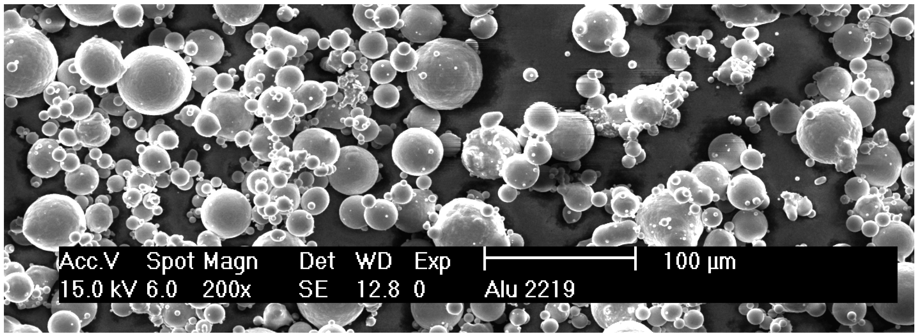
2.1. Prealloyed Argon Atomized Powder with Chemical Composition of EN AW-2219
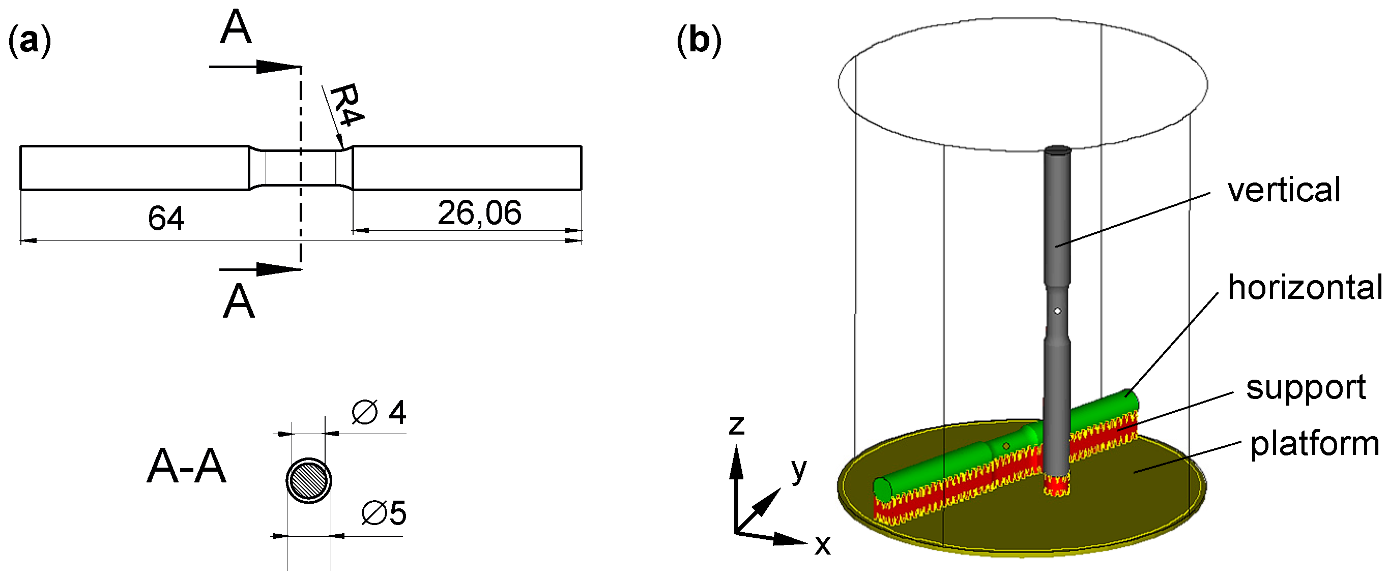
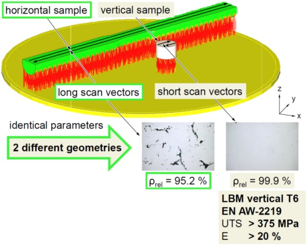
2.2. Tensile Specimen Geometry and Build-Up Orientation
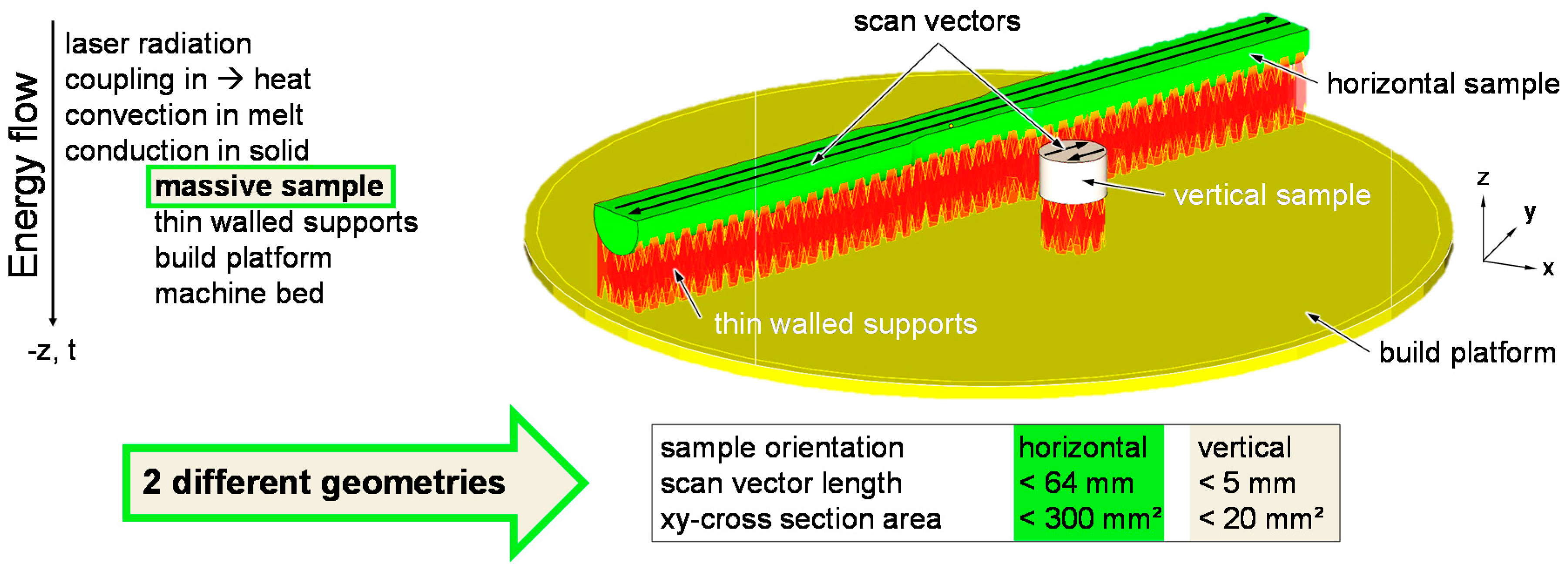
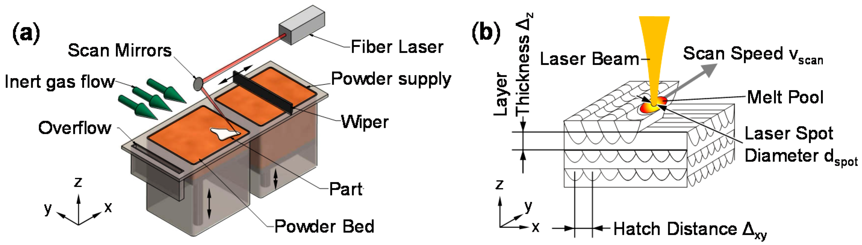
2.3. LBM Process
2.4. Post-LBM Processing of Samples
2.5. Metallography and Fractography
2.6. Mechanical Characterization
3. Experimental Results and Discussion
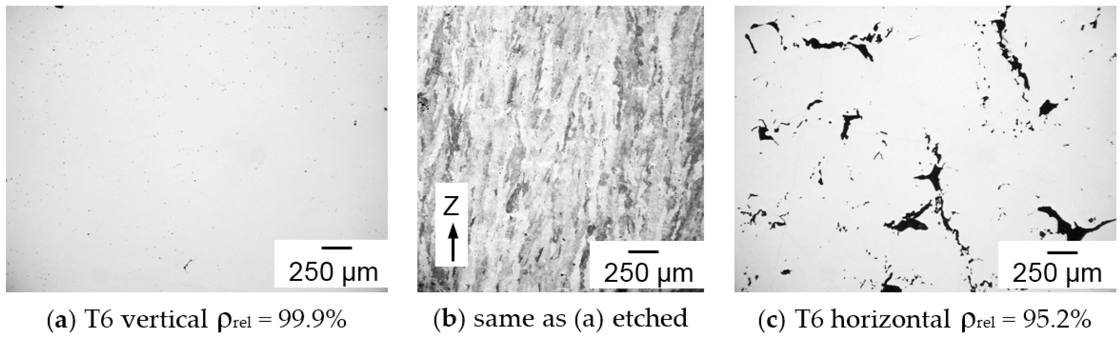
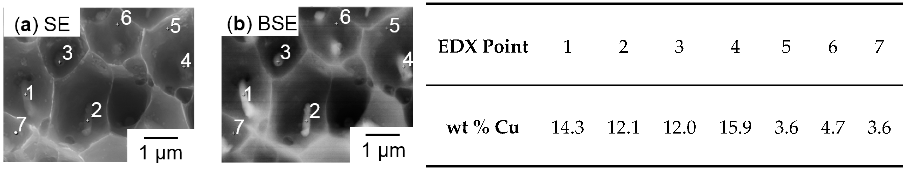
3.1. Metallography
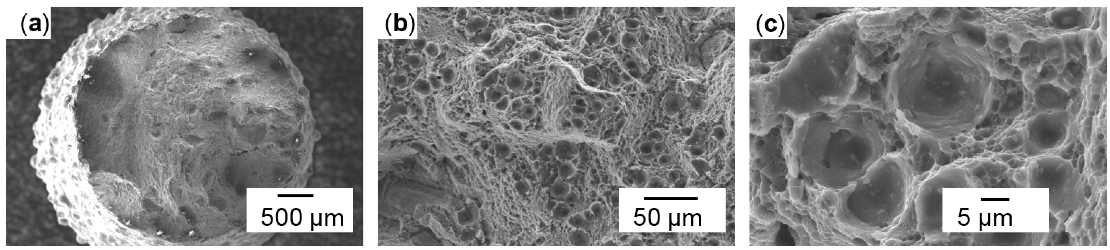
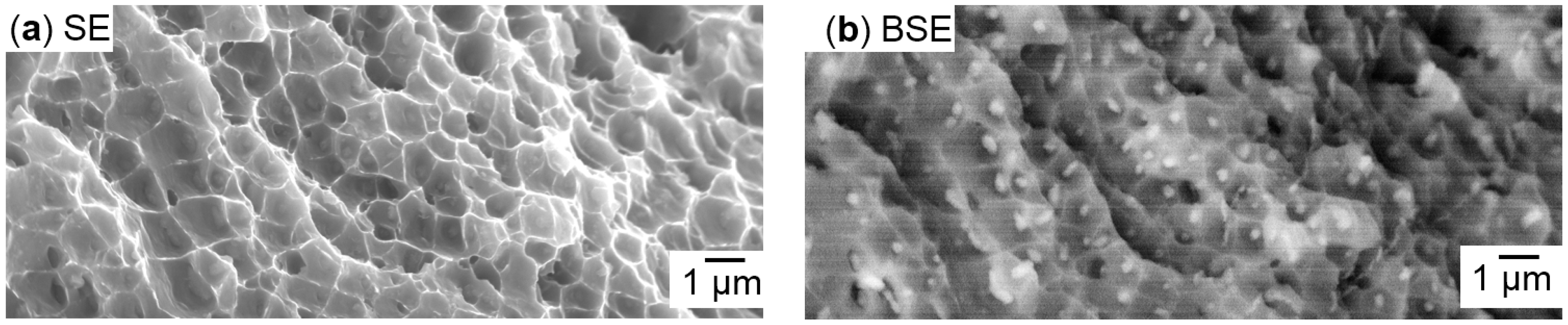
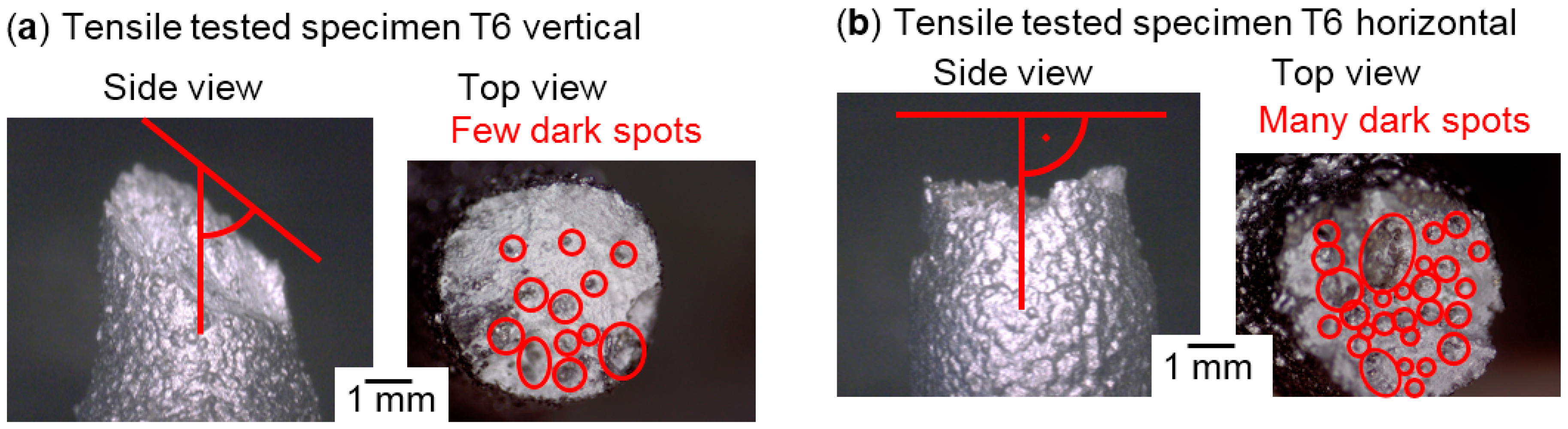
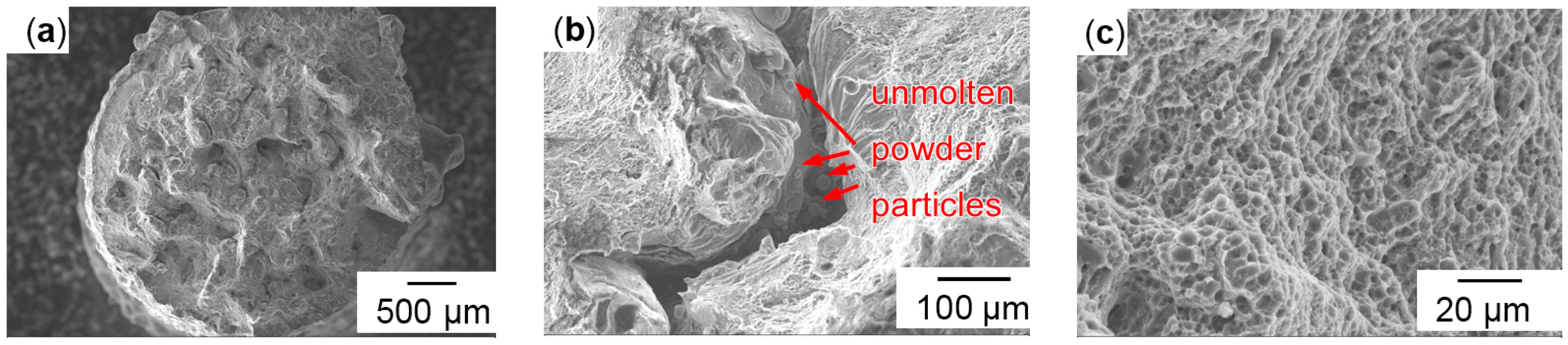
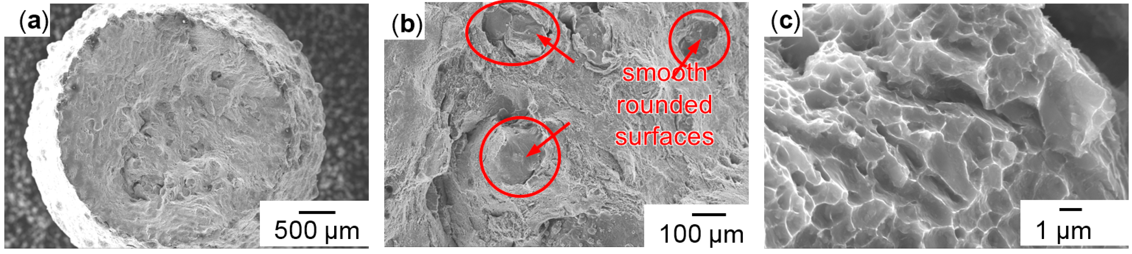
3.2. Fractography
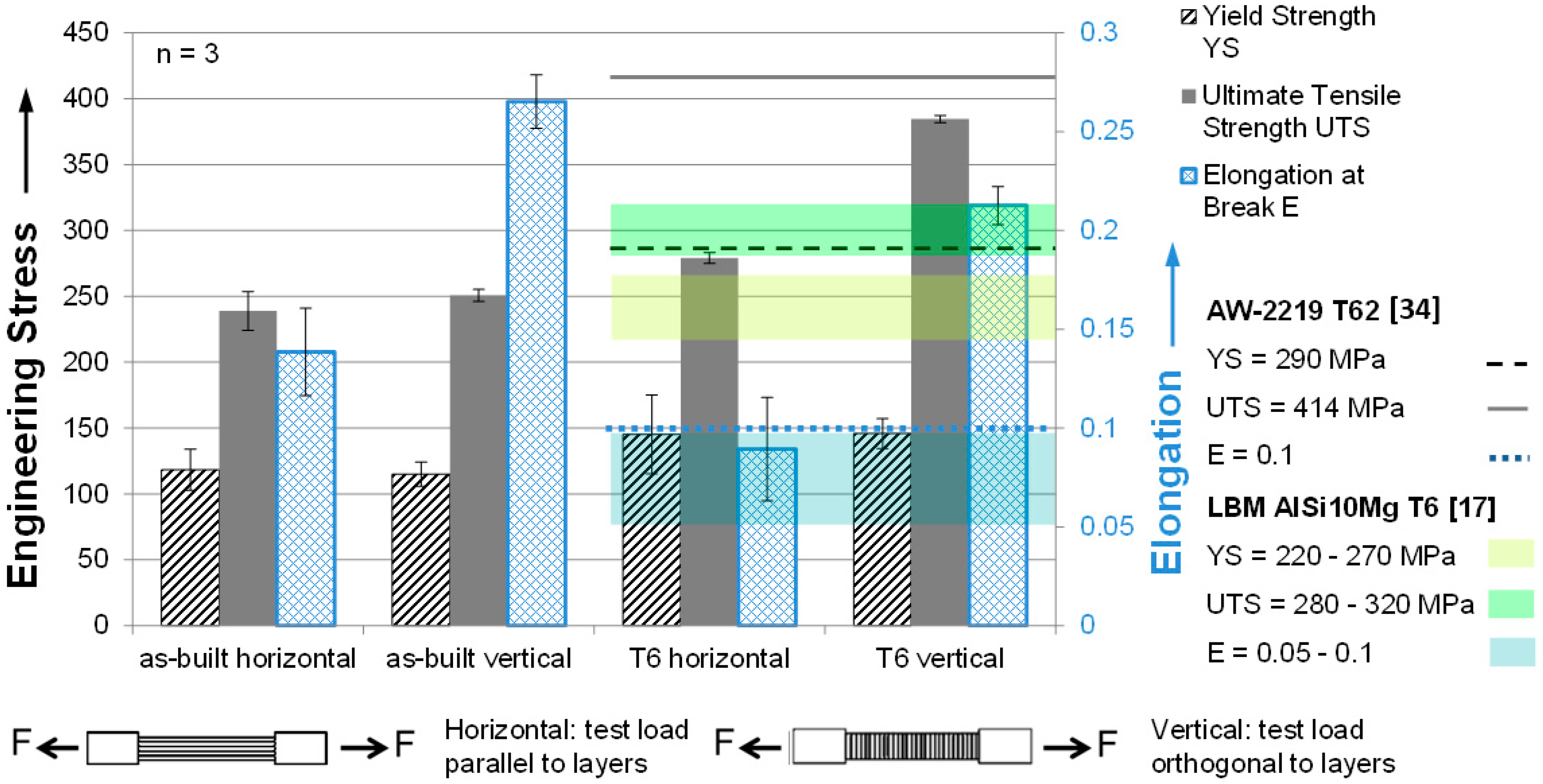
3.3. Mechanical Characterization
4. Conclusions
Acknowledgments
Author Contributions
Conflicts of Interest
References
- American Society for Testing Materials. Standard Terminology for Additive Manufacturing—General Principles—Terminology; ASTM52900; ASTM International: West Conshohocken, PA, USA, 2015. [Google Scholar]
- International Organization for Standardization. Additive Fertigung—Grundlagen—Teil 2: Überblick über Prozesskategorien und Ausgangswerkstoffe; ISO 17296-2:2015; International Organization for Standardization: Geneva, Switzerland, 2015. [Google Scholar]
- Verein Deutscher Ingenieure. Additive Fertigungsverfahren Grundlagen, Begriffe, Verfahrensbeschreibungen Additive Manufacturing Processes, Rapid Manufacturing Basics, Definitions, Processes; VDI Richtlinie 3405; Verein Deutscher Ingenieure: Duesseldorf, Germany, 2014. [Google Scholar]
- Wohlers, T.T.; Caffrey, T.U.; Campbell, R.I. Wohlers Report 2016: 3D Printing and Additive Manufacturing State of the Industry: Annual Worldwide Progress Report; Wohlers Associates: Fort Collins, CO, USA, 2016. [Google Scholar]
- European Committee for Standardization. Aluminium und Aluminiumlegierungen—Begriffe—Teil 1: Allgemeine Begriffe; Dreisprachige Fassung; EN 12258-1; European Committee for Standardization: Brussels, Belgium, 2012. [Google Scholar]
- European Committee for Standardization. Aluminium und Aluminiumlegierungen—Chemische Zusammensetzung und Form von Halbzeug—Teil 1: Numerisches Bezeichnungssystem; EN 573-1; European Committee for Standardization: Brussels, Belgium, 2004. [Google Scholar]
- European Committee for Standardization. Aluminium und Aluminiumlegierungen—Chemische Zusammensetzung und Form von Halbzeug—Teil 3: Chemische Zusammensetzung und Erzeugnisformen; Norm DIN EN 573-3:2009; European Committee for Standardization: Brussels, Belgium, 2009. [Google Scholar]
- European Committee for Standardization. Aluminium und Aluminiumlegierungen—Gussstücke—Chemische Zusammensetzung und Mechanische Eigenschaften; Deutsche Fassung EN 1706; European Committee for Standardization: Brussels, Belgium, 2010. [Google Scholar]
- The Aluminum Association. International Alloy Designations and Chemical Composition Limits for Wrought Aluminum and Wrought Aluminum Alloys; The Aluminum Association: Arlington, VA, USA, 2015. [Google Scholar]
- Hornbogen, E. Hundred years of precipitation hardening. J. Light Met. 2001, 1, 127–132. [Google Scholar] [CrossRef]
- Wiedemann, J. Leichtbau. Elemente und Konstruktion. Klassiker der Technik; Springer: Berlin/Heidelberg, Germany, 2007. [Google Scholar]
- Buchbinder, D.; Meiners, W.; Wissenbach, K.U.; Poprawe, R. Selective laser melting of aluminum die-cast alloy—Correlations between process parameters, solidification conditions, and resulting mechanical properties. J. Laser Appl. 2015, 27, S29205. [Google Scholar] [CrossRef]
- Buchbinder, D. Selective Laser Melting von Aluminiumgusslegierungen; Shaker: Herzogenrath, Germany, 2013. [Google Scholar]
- Kempen, K. Expanding the Materials Palette for Selective Laser Melting of Metals; Eigenverlag: Leuven, Belgium, 2015. [Google Scholar]
- Rao, H.; Giet, S.; Yang, K.; Wu, X.U.; Davies, C.H. The influence of processing parameters on aluminium alloy A357 manufactured by Selective Laser Melting. Mater. Des. 2016, 109, 334–346. [Google Scholar] [CrossRef]
- Herold, H.U.; Adam, T. Lexikon der Schweißtechnik: Schweißen, Schneiden und Verwandte Verfahren; Deutscher Verlag fuer Schweisstechnik: Magdeburg/Düsseldorf, Germany, 1994. [Google Scholar]
- Verein Deutscher Ingenieure. Additive Fertigungsverfahren, Laser-Strahlschmelzen Metallischer Bauteile—Materialkenndatenblatt Aluminiumlegierung AlSi10Mg; VDI Richtlinie 3405 Blatt 2.1:2015-07; Verein Deutscher Ingenieure: Duesseldorf, Germany, 2015. [Google Scholar]
- Buchbinder, D.; Schleifenbaum, H.; Heidrich, S.; Meiners, W.U.; Bültmann, J. High Power Selective Laser Melting (HP SLM) of Aluminum Parts. Phys. Procedia 2011, 12, 271–278. [Google Scholar] [CrossRef]
- Schmidtke, K.; Palm, F.; Hawkins, A.U.; Emmelmann, C. Process and Mechanical Properties. Applicability of a Scandium modified Al-alloy for Laser Additive Manufacturing. Phys. Procedia 2011, 12, 369–374. [Google Scholar] [CrossRef]
- Spierings, A.B.; Dawson, K.; Voegtlin, M.; Palm, F.U.; Uggowitzer, P.J. Microstructure and mechanical properties of as-processed scandium-modified aluminium using selective laser melting. CIRP Ann. Manuf. Technol. 2016, 65, 213–216. [Google Scholar] [CrossRef]
- Buchbinder, D.; Meiners, W.; Brandl, E.; Palm, F.; Müller-Lohmeier, K.; Wolter, M.; Over, C.; Moll, W.; Weber, J.; Skrynecki, N.; et al. Generative Fertigung von Aluminiumbauteilen für die Serienproduktion—AluGenerativ. Abschlussbericht. Available online: http://publica.fraunhofer.de/dokumente/N-203765.html (accessed on 12 January 2017).
- Ober, J.A. Mineral Commodity Summaries 2016; U.S. Geological Survey: Reston, VA, USA, 2016.
- Kaufmann, N.; Imran, M.; Wischeropp, T.M.; Emmelmann, C.; Siddique, S.U.; Walther, F. Influence of process parameters on the quality of aluminium alloy EN AW 7075 using selective laser melting (SLM). Phys. Procedia 2016, 83, 918–926. [Google Scholar] [CrossRef]
- Karg, M.; Hentschel, O.; Ahuja, B.U.; Schmidt, M. Determination of Cooling Rates During Laser Beam Melting of Aluminium Alloy EN AW 7075 Using High Speed Pyrometry. Talent Driven Innovation. In Proceedings of the 15th Annual International Conference on Rapid Product Development Association of South Africa, Stellenbosch, South Africa, 5–7 November 2014.
- Montero Sistiaga, M.L.; Mertens, R.; Vrancken, B.; Wang, X.; van Hooreweder, B.; Kruth, J.-P.U.; van Humbeeck, J. Changing the alloy composition of Al7075 for better processability by selective laser melting. J. Mater. Process. Technol. 2016, 238, 437–445. [Google Scholar] [CrossRef]
- Wang, P.; Li, H.C.; Prashanth, K.G.; Eckert, J.U.; Scudino, S. Selective laser melting of Al–Zn–Mg–Cu. Heat treatment, microstructure and mechanical properties. J. Alloy. Compd. 2016, in press. [Google Scholar] [CrossRef]
- Fulcher, B.; Leigh, D.U.; Watt, T. Comparison of AlSi10Mg and Al 6061 Processed Through DMLS. In Proceedings of the Solid Freeform Fabrication Symposium, Austin, TX, USA, 4–6 August 2014; pp. 404–419.
- Roberts, C.E.; Bourell, D.; Watt, T.U.; Cohen, J. A novel processing approach for additive manufacturing of commercial aluminum alloys. Phys. Procedia 2016, 83, 909–917. [Google Scholar] [CrossRef]
- Karg, M.C.H.; Ahuja, B.; Kuryntsev, S.U.; Schmidt, M. Processability of high strength aluminium-copper alloys AW-2022 and 2024 by laser beam melting in powder bed. In Proceedings of the Solid Freeform Fabrication Symposium, Austin, TX, USA, 4–6 August 2014; pp. 420–436.
- Ahuja, B.; Karg, M.; Nagulin, K.Y.U.; Schmidt, M. Fabrication and characterization of high strength Al–Cu alloys processed using laser beam melting in metal powder bed. Phys. Procedia 2014, 56, 135–146. [Google Scholar] [CrossRef]
- Karg, M.; Ahuja, B.; Schaub, A.; Schmidt, J.; Sachs, M.; Mahr, A.; Wiesenmayer, S.; Wigner, L.; Wirth, K.-E.; Peukert, W.; et al. Effect of process conditions on mechanical behavior of aluminium wrought alloy EN AW-2618A additively manufactured by laser beam melting in powder bed. Lasers in manufacturing 2015. In Proceedings of the 8th International WLT Conference on Lasers in Manufacturing, Munich, Germany, 22–25 June 2015.
- Zhang, H.; Zhu, H.; Qi, T.; Hu, Z.U.; Zeng, X. Selective laser melting of high strength Al–Cu–Mg alloys: Processing, microstructure and mechanical properties. Mater. Sci. Eng. A 2016, 656, 47–54. [Google Scholar] [CrossRef]
- Koutny, D.; Palousek, D.; Koukal, O.; Zikmund, T.; Pantelejev, L.; Dokoupil, F. Processing of high strength Al–Cu alloy using 400W selective laser melting—Initial study. Lasers in manufacturing 2015. In Proceedings of the 8th International WLT Conference on Lasers in Manufacturing, Munich, Germany, 22–25 June 2015.
- Material Data Sheet Aluminum 2219-T62. Available online: http://asm.matweb.com/search/SpecificMaterial.asp?bassnum=MA2219T62 (accessed on 17 November 2016).
- International Organization for Standardization. Metallische Werkstoffe—Zugversuch—Teil 1: Prüfverfahren bei Raumtemperatur; ISO 6892-1; International Organization for Standardization: Geneva, Switzerland, 2014. [Google Scholar]
- International Organization for Standardization. Metallische Werkstoffe—Härteprüfung nach Vickers—Teil 1: Prüfverfahren; ISO 6507-1; International Organization for Standardization: Geneva, Switzerland, 2005. [Google Scholar]
- Ahuja, B.; Karg, M.C.H.; Schmidt, M. Laser beam melting of high strength aluminium alloys EN AW-6061 and EN AW-6082. In Proceedings of the 5th International Conference on Additive Technologies iCAT 2014, Vienna, Austria, 16–17 October 2014; pp. 153–158.


| Cu | Mn | Ti | V | Zr | Zn | Mg | Si | Fe | Al |
|---|---|---|---|---|---|---|---|---|---|
| 5.8–6.8 | 0.2–0.4 | 0.02–0.1 | 0.05–0.15 | 0.1–0.25 | 0.1 | 0.02 | 0.2 | 0.3 | balance |
| PLaser | vscan | Δxy | Δz | dspot | Tplatform | Gas |
|---|---|---|---|---|---|---|
| 100 W | 157 mm/s | 90 µm | 30 µm | 65 µm | 200 °C | Ar |
| Alloy | EN AW-2219 | EN AW-2219 | EN AW-2219 | AlSi10Mg | AlSi10Mg |
| Processed | LBM | LBM | Conventional [34] | LBM [19] | LBM [13] |
| Heat Treatment | As-built | T6 | T62 | As-built | T6 |
| Mean | 94 HV0.05 n = 9 | 147 HV0.05 n = 9 | 130 HV | 140–150 HV | 80–120 HV |
| Standard Deviation | 6.6 HV0.05 n = 9 | 2.3 HV0.05 n = 9 | - | - | - |
© 2017 by the authors. Licensee MDPI, Basel, Switzerland. This article is an open access article distributed under the terms and conditions of the Creative Commons Attribution (CC-BY) license ( http://creativecommons.org/licenses/by/4.0/).
Share and Cite
Karg, M.C.H.; Ahuja, B.; Wiesenmayer, S.; Kuryntsev, S.V.; Schmidt, M. Effects of Process Conditions on the Mechanical Behavior of Aluminium Wrought Alloy EN AW-2219 (AlCu6Mn) Additively Manufactured by Laser Beam Melting in Powder Bed. Micromachines 2017, 8, 23. https://doi.org/10.3390/mi8010023
Karg MCH, Ahuja B, Wiesenmayer S, Kuryntsev SV, Schmidt M. Effects of Process Conditions on the Mechanical Behavior of Aluminium Wrought Alloy EN AW-2219 (AlCu6Mn) Additively Manufactured by Laser Beam Melting in Powder Bed. Micromachines. 2017; 8(1):23. https://doi.org/10.3390/mi8010023
Chicago/Turabian StyleKarg, Michael Cornelius Hermann, Bhrigu Ahuja, Sebastian Wiesenmayer, Sergey Vyacheslavovich Kuryntsev, and Michael Schmidt. 2017. "Effects of Process Conditions on the Mechanical Behavior of Aluminium Wrought Alloy EN AW-2219 (AlCu6Mn) Additively Manufactured by Laser Beam Melting in Powder Bed" Micromachines 8, no. 1: 23. https://doi.org/10.3390/mi8010023