
Glass Imprint Templates by Spark Assisted Chemical Engraving for Microfabrication by Hot Embossing


Abstract
:1. Introduction
2. Materials and Methods
3. Results and Discussion
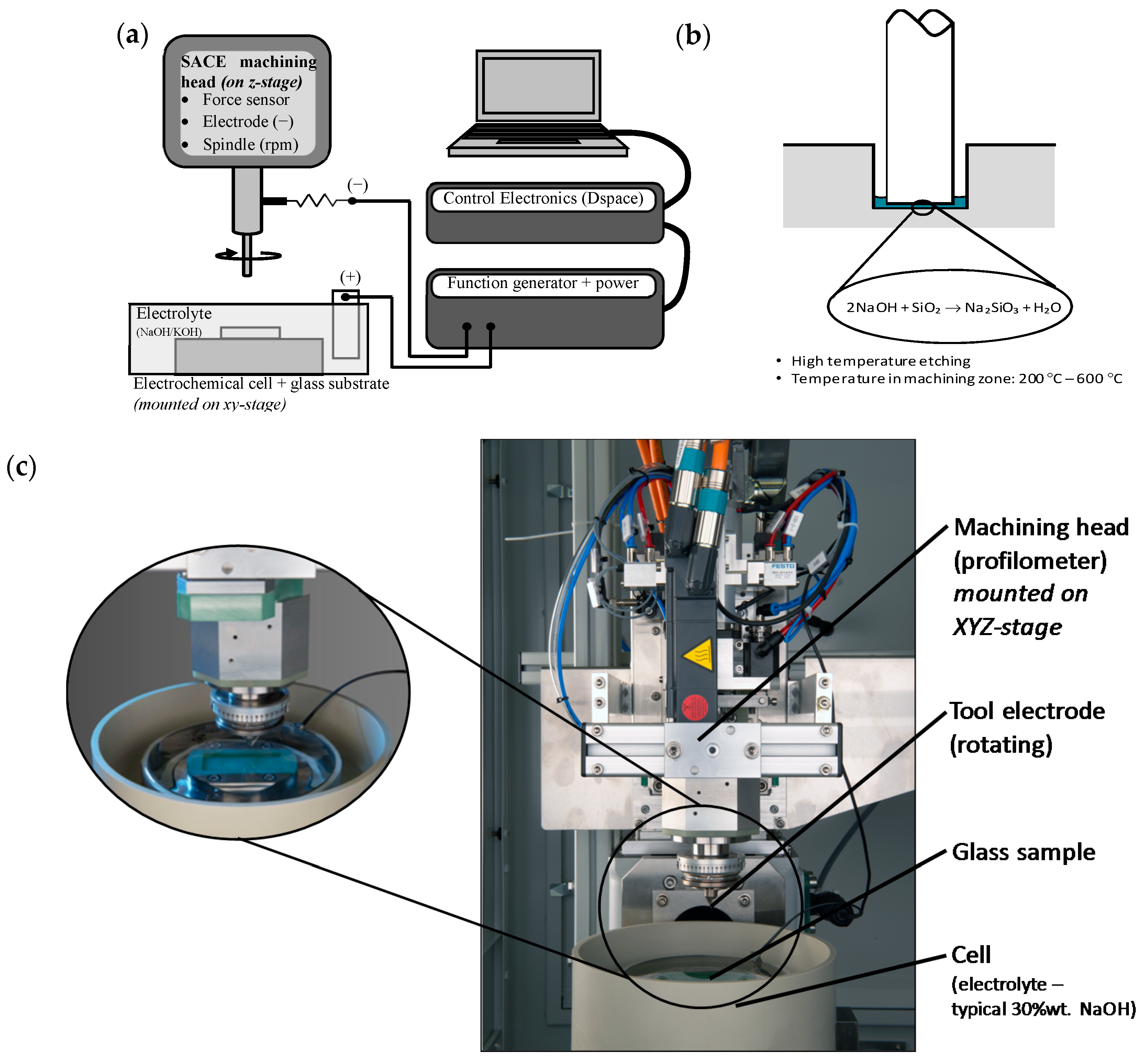
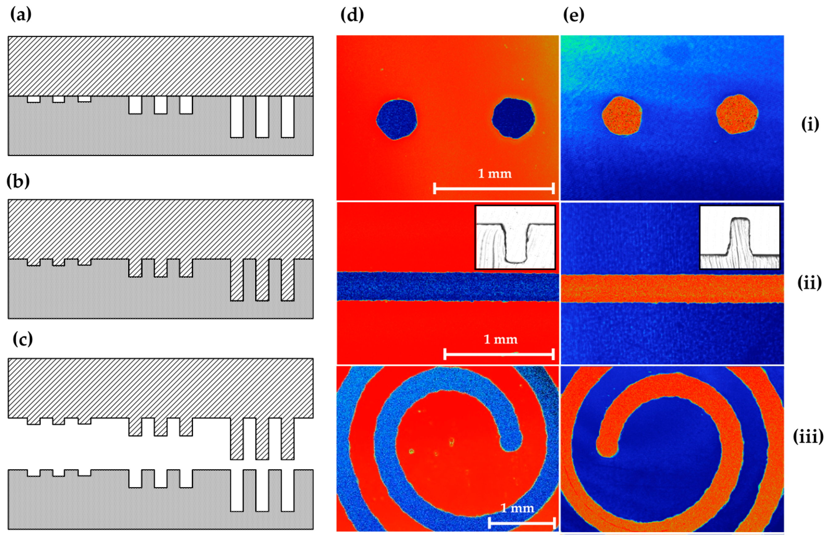
3.1. Mould Fabrication Using SACE
3.1.1. System Operation
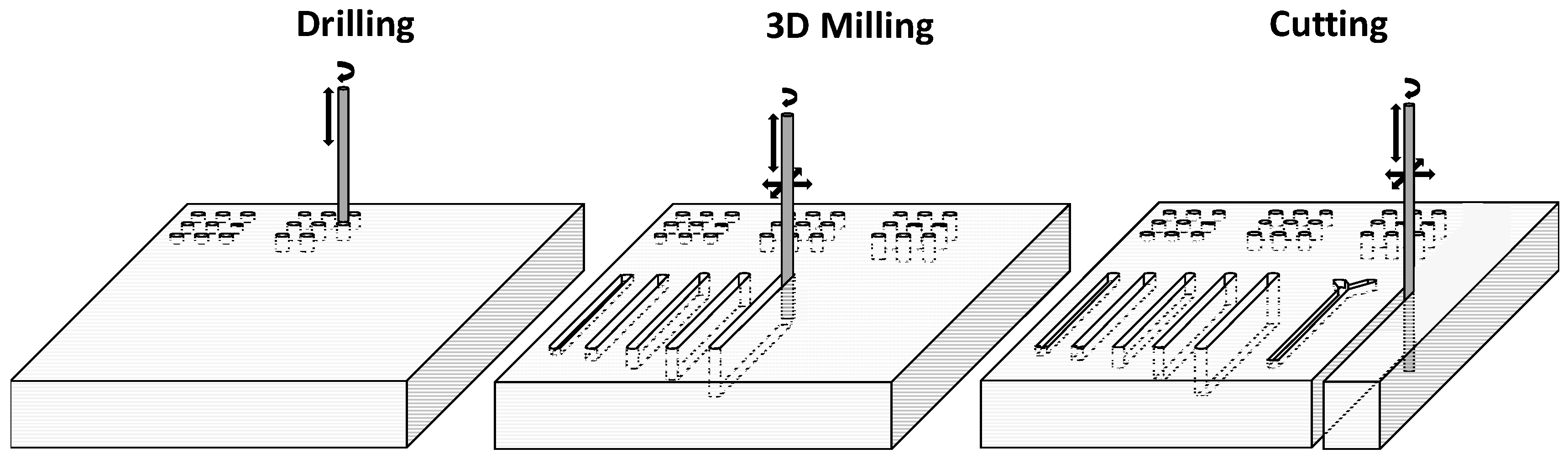
3.1.2. Control over 3D Structure
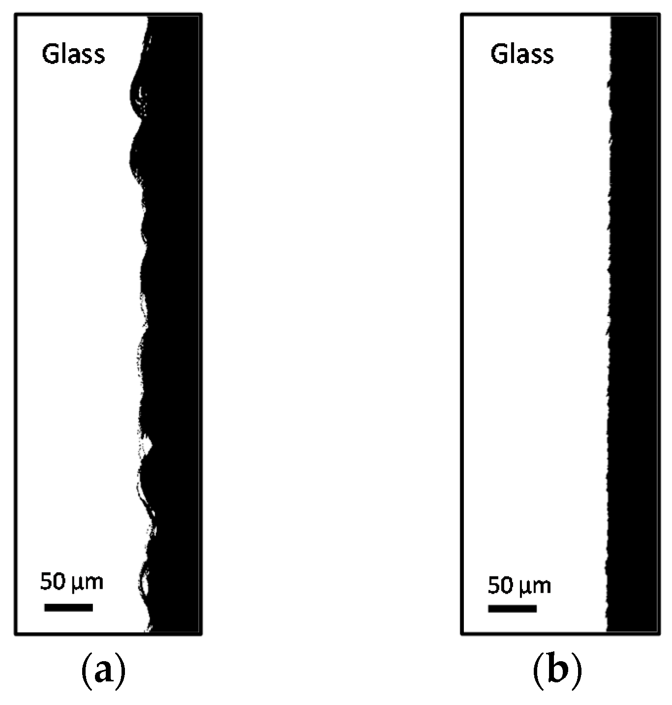
3.1.3. Surface Smoothness for Hot Embossing Applications
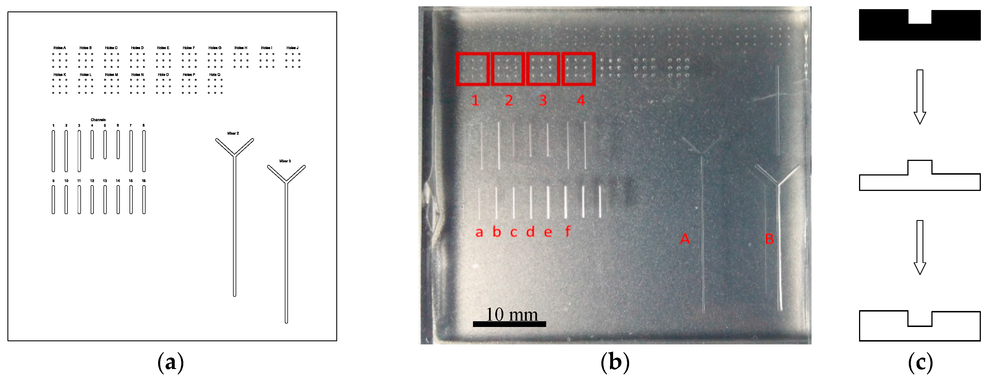
3.1.4. Fabrication and Evaluation of a Glass Imprint Template
3.1.5. Time to Create a Stamp
3.2. Use of Glass Moulds as Imprint Templates for Microfabrication
3.2.1. Glass Properties
3.2.2. Embossing Protocol
3.3. Repetitive Embossing Using a SACE Imprint Template
3.4. Discussion
4. Conclusions
Acknowledgments
Author Contributions
Conflicts of Interest
References
- Berthier, E.; Young, E.W.K.; Beebe, D. Engineers are from PDMS-land, biologists are from polystyrenia. Lab Chip 2012, 12, 1224–1237. [Google Scholar] [CrossRef] [PubMed]
- Yole Development Market and Technology Trends for Microfluidic Applications—21 September 2011. Unpublished work.
- Cameron, N.S.; Roberge, H.; Veres, T.; Jakeway, S.C.; John Crabtree, H. High fidelity, high yield production of microfluidic devices by hot embossing lithography: Rheology and stiction. Lab Chip 2006, 6, 936–941. [Google Scholar] [CrossRef] [PubMed] [Green Version]
- Greener, J.; Li, W.; Ren, J.; Voicu, D.; Pakharenko, V.; Tang, T.; Kumacheva, E. ESI: Rapid, cost-efficient fabrication of microfluidic reactors in thermoplastic polymers by combining photolithography and hot embossing. Lab Chip 2010, 10, 522–524. [Google Scholar] [CrossRef] [PubMed]
- Leech, P.W. Hot Embossing of Microchannels in Cyclic Olefin Copolymer. Camb. J. Online 2009, 1191, 1–12. [Google Scholar] [CrossRef]
- Gates, B.D.; Xu, Q.; Love, J.C.; Wolfe, D.B.; Whitesides, G.M. Unconventional nanofabrication. Annu. Rev. Mater. Res. 2004, 34, 339–372. [Google Scholar] [CrossRef]
- Yao, D.; Nagarajan, P.; Li, L.; Yi, A.Y. A two-station embossing process for rapid fabrication of surface microstructures on thermoplastic polymers. Polym. Eng. Sci. 2007, 47, 530–539. [Google Scholar] [CrossRef]
- Schaller, T.; Bohn, L.; Mayer, J.; Schubert, K. Microstructure grooves with a width of less than 50 μm cut with ground hard metal micro end mills. Precis. Eng. 1999, 23, 229–235. [Google Scholar] [CrossRef]
- Shiu, P.P.; Knopf, G.K.; Ostojic, M.; Nikumb, S. Rapid fabrication of tooling for microfluidic devices via laser micromachining and hot embossing. J. Micromech. Microeng. 2008, 18, 25012. [Google Scholar] [CrossRef]
- Shibata, T.; Takahashi, Y.; Kawashima, T.; Kubota, T.; Mita, M.; Mineta, T.; Makino, E. Micromachining of electroformed nickel mold using thick photoresist microstructure for imprint technology. Microsyst. Technol. 2008, 14, 1359–1365. [Google Scholar] [CrossRef]
- Novak, R.; Ranu, N.; Mathies, R.A. Rapid fabrication of nickel molds for prototyping embossed plastic microfluidic devices. Lab Chip 2013, 13, 1468–1471. [Google Scholar] [CrossRef] [PubMed]
- Debono, M.; Voicu, D.; Pousti, M.; Safdar, M.; Young, R.; Kumacheva, E.; Greener, J. One-step fabrication of microchannels with integrated three dimensional features by hot intrusion embossing. Sensors 2016, 16, 2023. [Google Scholar] [CrossRef] [PubMed]
- Zhang, L.; Gu, F.; Tong, L.; Yin, X. Simple and cost-effective fabrication of two-dimensional plastic nanochannels from silica nanowire templates. Microfluid. Nanofluid. 2008, 5, 727–732. [Google Scholar] [CrossRef]
- Niino, H.; Ding, X.; Kurosaki, R.; Narazaki, A.; Sato, T.; Kawaguchi, Y. Imprinting by hot embossing in polymer substrates using a template of silica glass surface-structured by the ablation of LIBWE method. Appl. Phys. A 2004, 79, 827–828. [Google Scholar] [CrossRef]
- Iliescu, C.; Taylor, H.; Avram, M.; Miao, J.; Franssila, S. A practical guide for the fabrication of microfluidic devices using glass and silicon. Biomicrofluidics 2012, 6, 016505. [Google Scholar] [CrossRef] [PubMed]
- Wüthrich, R.; Ziki, J.D.A. Micromachining Using Electrochemical Discharge Phenomenon, 2nd ed.; Wüthrich, R., Ziki, J.D.A., Eds.; William Andrew Publishing: Boston, MA, USA, 2015. [Google Scholar]
- Van Toan, N.; Toda, M.; Ono, T. An investigation of processes for glass micromachining. Micromachines 2016, 7, 19–22. [Google Scholar] [CrossRef]
- Liu, J.W.; Huang, Q.A; Shang, J.T.; Tang, J.Y. Micromachining of Pyrex7740 Glass for Micro-Fluidic Devices. In Proceedings of the 14th International Conference on Miniaturized Systems for Chemistry and Life Sciences, Groningen, The Netherlands, 3–7 October 2010; pp. 1907–1909.
- Haque, R.U.M.; Wise, K.D. A glass-in-silicon reflow process for three-dimensional microsystems. J. Microelectromech. Syst. 2013, 22, 1470–1477. [Google Scholar] [CrossRef]
- Wüthrich, R.; Fascio, V. Machining of non-conducting materials using electrochemical discharge phenomenon—An overview. Int. J. Mach. Tools Manuf. 2005, 45, 1095–1108. [Google Scholar] [CrossRef]
- Abou Ziki, J.D.; Hof, L.A.; Wüthrich, R. The machining temperature during spark assisted chemical engraving of glass. Manuf. Lett. 2015, 3, 9–13. [Google Scholar] [CrossRef]
- Le Bourhis, E. Glass, Mechanics and Technology; Wiley-VCH: Weinheim, Germany, 2014. [Google Scholar]
- Zumdahl, S.S.; DeCoste, D.J. Introductory Chemistry, 7th ed.; White, A., Ed.; Brooks/Cole, Cengage Learning: Boston, MA, USA, 2010. [Google Scholar]
- Boyd, D.C.; Danielson, P.S.; Thompson, D.A.; Velez, M.; Reis, S.T.; Brow, R. Glass. In Kirk-Othmer Encyclopedia of Chemical Technology; Wiley: Hoboken, NJ, USA, 2004. [Google Scholar]
- Zheng, Z.-P.; Su, H.-C.; Huang, F.-Y.; Yan, B.-H. The tool geometrical shape and pulse-off time of pulse voltage effects in a Pyrex glass electrochemical discharge microdrilling process. J. Micromech. Microeng. 2007, 17, 265–272. [Google Scholar] [CrossRef]
- Cao, X.D.; Kim, B.H.; Chu, C.N. Micro-structuring of glass with features less than 100 μm by electrochemical discharge machining. Precis. Eng. 2009, 33, 459–465. [Google Scholar] [CrossRef]
- Chak, S.K.; Venkateswara Rao, P. The drilling of Al2O3 using a pulsed DC supply with a rotary abrasive electrode by the electrochemical discharge process. Int. J. Adv. Manuf. Technol. 2008, 39, 633–641. [Google Scholar] [CrossRef]
- Liu, J.W.; Yue, T.M.; Guo, Z.N. An analysis of the discharge mechanism in electrochemical discharge machining of particulate reinforced metal matrix composites. Int. J. Mach. Tools Manuf. 2010, 50, 86–96. [Google Scholar] [CrossRef]
- Kim, M.; Moon, B.-U.; Hidrovo, C.H. Enhancement of the thermo-mechanical properties of PDMS molds for the hot embossing of PMMA microfluidic devices. J. Micromech. Microeng. 2013, 23, 95024. [Google Scholar] [CrossRef]
- Jaszewski, R.W.; Schift, H.; Gobrecht, J.; Smith, P. Hot embossing in polymers as a direct way to pattern resist. Microelectron. Eng. 1998, 41, 575–578. [Google Scholar] [CrossRef]
- Soga, N. Elastic moduli and fracture toughness of glass. J. Non Cryst. Solids 1985, 73, 305–313. [Google Scholar] [CrossRef]
- Yamane, M.; Mackenzie, J.D. Vicker’s Hardness of glass. J. Non Cryst. Solids 1974, 15, 153–164. [Google Scholar] [CrossRef]
- Saint Gobain Glass Glass Physical Properties. Available online: http://uk.saint-gobain-glass.com/trade-customers/physical-properties (accessed on 15 February 2016).
- Wilantewicz, T.E.; Varner, J.R. Vickers indentation behavior of several commercial glasses at high temperatures. J. Mater. Sci. 2008, 43, 281–298. [Google Scholar] [CrossRef]
- Denry, I.L.; Holloway, J.A. Elastic constants, Vickers hardness, and fracture toughness of fluorrichterite-based glass-ceramics. Dent. Mater. 2004, 20, 213–219. [Google Scholar] [CrossRef]
- Matzke, H.; Toscano, E.; Routbort, J.; Reimann, K. Temperature dependence and fracture toughness and elastic moduli of a waste glass. J. Am. Ceram. Soc. 1986, 69, C-138–C-139. [Google Scholar] [CrossRef]
- Petit, F.; Sartieaux, A.C.; Gonon, M.; Cambier, F. Fracture toughness and residual stress measurements in tempered glass by Hertzian indentation. Acta Mater. 2007, 55, 2765–2774. [Google Scholar] [CrossRef]
- Johnston, I.D.; McCluskey, D.K.; Tan, C.K.L.; Tracey, M.C. Mechanical characterization of bulk Sylgard 184 for microfluidics and microengineering. J. Micromech. Microeng. 2014, 24, 35017. [Google Scholar] [CrossRef]
- MIT Material Properties PDMS. Available online: http://www.mit.edu/~6.777/matprops/pdms.htm (accessed on 5 March 2016).
- Greer, A.I.M.; Vasiev, I.; Della-Rosa, B.; Gadegaard, N. Fluorinated ethylene–propylene: A complementary alternative to PDMS for nanoimprint stamps. Nanotechnology 2015, 27, 155301. [Google Scholar] [CrossRef] [PubMed]
- Microchem Material Properties. Available online: http://www.microchem.com/pdf/SU-8 3000 Data Sheet.pdf (accessed on 5 March 2016).
- Hammacher, J.; Fuelle, A.; Flaemig, J.; Saupe, J.; Loechel, B.; Grimm, J. Stress engineering and mechanical properties of SU-8-layers for mechanical applications. Microsyst. Technol. 2008, 14, 1515–1523. [Google Scholar] [CrossRef]
- Jena, R.K.; Yue, C.Y.; Yun, K.X. Effect of a CNT based composite micromold on the replication fidelity during the microfabrication of polymeric microfluidic devices. RSC Adv. 2014, 4, 12448–12456. [Google Scholar] [CrossRef]
- Cytec Idustries Inc. Conapoxy FR-1080. Available online: http://www.needfill.co.kr/cd/FR-1080.html (accessed on 5 March 2016).
- Ellsworthadhesives Epoxy Resins Material Properties. Available online: http://www.ellsworthadhesives.co.uk/media/wysiwyg/files/cytec/CytecElectronicsBrochure-EU.pdf (accessed on 5 March 2016).
- Statistics based on 2011–2016 order statistics from FlowJEM Inc. Unpublished work.


| Feature | Machining Mode | Electrolyte | Pulsed Voltage Input | |||
|---|---|---|---|---|---|---|
| High Level | Low Level | Period | Duty Cycle | |||
| Channels/lines | Constant depth-of-cut (50 µm) × n | 20 wt % KOH | 36 V | 17.5 V | 2.6 ms | 96.15% |
| Holes | Gravity feed drilling | 20 wt % KOH | 36 V | 17.5 V | 2.6 ms | 96.15% |
| Material | Linear Temp. Expansion Coefficient (µm∙(m∙k)−1) | Thermal Conductivity (W∙(m∙k)−1) | Hardness (GPa) | Fracture Toughness (MPa∙m1/2) | Tensile Strength (MPa) | Compressive Strength (MPa) |
|---|---|---|---|---|---|---|
| Glass borosilicate (toughened) [33] | 4.0 | 1.05 | 6.2 [34,35] | 0.7 [36]/2 [37] | 30/200 | 1000 |
| PDMS (Stylgard 184) [38] | 310 | 0.15 [39] | N/A 1 | - | 7 [40] | 2–50 |
| Photoresist (SU-8 series) [41] | 52 | 0.2 | 0.3 [42] | - | 73 | - |
| Epoxy resins [43] | - | - | N/A 2 [43,44] | 400 | 70 [45] | - |
| Ni | 13.0 | 91 | 6.3–11.8 | 100–150 | - | - |
| Material | Material Properties | Embossing Conditions | ||||
|---|---|---|---|---|---|---|
| Tg 1 (°C) | Tm 1 (°C) | td 2 (min) | Te/Td 3 (°C) | p 4 (PSI) | te 5 (min) | |
| COP | 138 | 210 | 50–100 | 150/130 | 70 | 5 |
| PMMA | 113 | 160 | 75–90 | 145/80 | 130 | 5 |
| PC | 149 | 155 | 40–80 | 175/145 | 150 | 5 |
| PS | 101 | 240 | 70–80 | 115–125/100 | 120–130 | 5 |
| PP | −6 | 164 | N/A | 145/100 | 150 | 5 |
| Feature | Glass Template | 1st Embossing | 5th Embossing | 11th Embossing | Feature Statistics Line a, d, f | ||||||||||
|---|---|---|---|---|---|---|---|---|---|---|---|---|---|---|---|
| Name | d | Image | d | w | Rq | d | w | Rq | d | w | Rq | d | w | Rq | Average d, w, Rq |
| Line a | 50 |  | 42 | 251 | 6.9 | 42 | 237 | 5.3 | 42 | 239 | 3.5 | 41 | 239 | 3.1 |  |
| Line d | 350 |  | 361 | 318 | 8.8 | 362 | 316 | 8.8 | 358 | 313 | 5.0 | 359 | 312 | 8.4 | 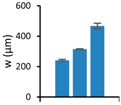 |
| Line f | 550 |  | 565 | 457 | 11.6 | 556 | 471 | 18.5 | 560 | 491 | 9.4 | 554 | 451 | 6.2 | 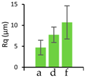 |
© 2017 by the authors. Licensee MDPI, Basel, Switzerland. This article is an open access article distributed under the terms and conditions of the Creative Commons Attribution (CC BY) license ( http://creativecommons.org/licenses/by/4.0/).
Share and Cite
Hof, L.A.; Guo, X.; Seo, M.; Wüthrich, R.; Greener, J. Glass Imprint Templates by Spark Assisted Chemical Engraving for Microfabrication by Hot Embossing. Micromachines 2017, 8, 29. https://doi.org/10.3390/mi8010029
Hof LA, Guo X, Seo M, Wüthrich R, Greener J. Glass Imprint Templates by Spark Assisted Chemical Engraving for Microfabrication by Hot Embossing. Micromachines. 2017; 8(1):29. https://doi.org/10.3390/mi8010029
Chicago/Turabian StyleHof, Lucas Abia, Xin Guo, Minseok Seo, Rolf Wüthrich, and Jesse Greener. 2017. "Glass Imprint Templates by Spark Assisted Chemical Engraving for Microfabrication by Hot Embossing" Micromachines 8, no. 1: 29. https://doi.org/10.3390/mi8010029