2.1. Required Specifications
Motile microorganisms move within an aquatic environment in three dimensions (3D), which makes it considerably difficult to continuously observe the target microorganism. Reducing the movement of the cell to only 2D would drastically simplify both the observation and stimulation processes. This can be achieved using a thin microfluidic chip that bounds the movement of the cell in the vertical plane. It is worth mentioning that the moving directions of the motile cell could be further decreased from 2D to 1D by introducing the cell into a flow path with a microchannel on a microchip. However, in the case of a motile microorganism, much labor is required to induce it to the desired position by fluidic control. Therefore, a microfluidic chip with a flat space is utilized for our platform. The thickness of the flat space can be precisely adjusted by using a microfabrication technique.
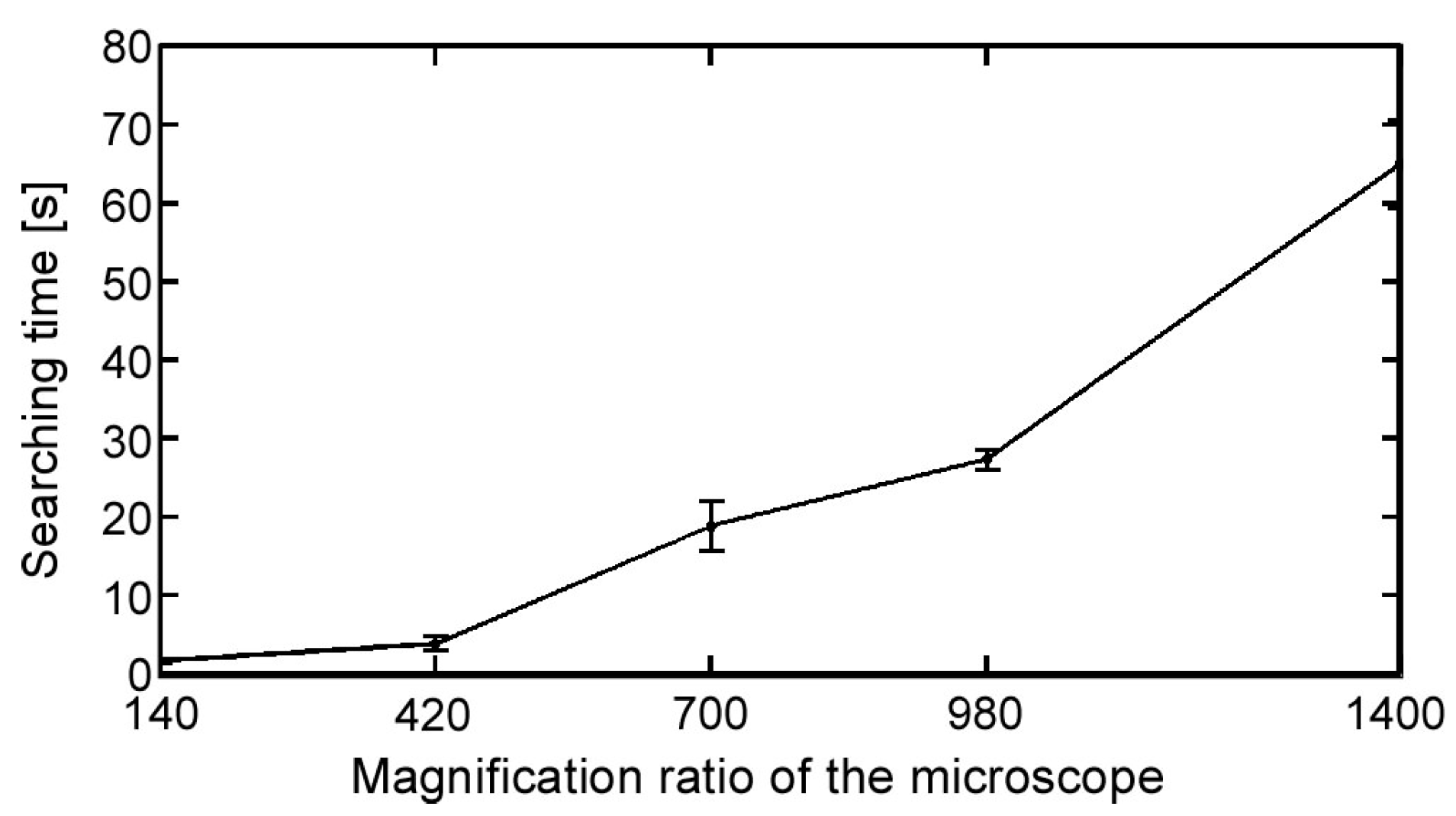
It is relatively easy to observe the position and movement of a swimming microorganism in a low-magnification environment. However, a high magnification ratio is preferred to observe specific behavior and reactions. Consequently, the relative speed of microorganisms increases with an increasing magnification ratio because the time duration of the microorganisms in the observation FOV decreases. Therefore, tracking the position of a single microorganism continuously is quite difficult. Therefore, to best obtain observations with a high magnification ratio, together with a high spatial resolution, a high-speed online vision sensor is required. In addition, it is difficult to conduct the experiment starting immediately from a highly magnified environment, especially in the searching process, which is a laborious task. Therefore, a seamless magnification changing mechanism is also needed to improve the efficiency of the experiment.
On the other hand, because our platform is designed to apply to real-time stimulation, the stimulation tool might reduce the tracking stability, especially when the tool is in direct contact with the target cell (e.g., mechanical stimulation). Moreover, the microorganism behavior must be observed after applying the stimulation to confirm the effect of the stimulation on the cell. Therefore, to build an effective tracking system, we must recognize the position of the target regardless of other objects visible in the FOV that we consider as noise. In fact, it is possible to eliminate the image noises using conventional image processing algorithms for object detection and classification [
17,
18]. Nonetheless, we must use a high-speed online vision sensor, which implies that the processing time for each frame is small and thus that it would be difficult to use time-consuming detection algorithms. Hence, a maximally simplified, robust image processing technique is required.
2.2. System Components
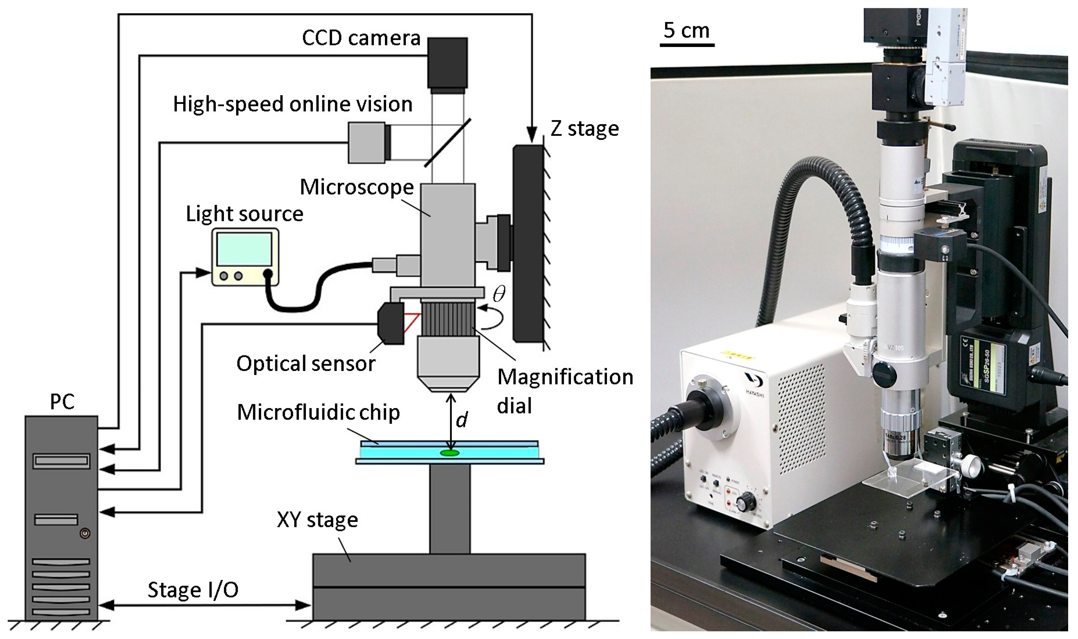
Figure 2 shows the basic components of the developed microrobotic platform. A high-speed online vision sensor (IDP-ExpressR2000, Photron Inc., Tokyo, Japan) [
19] was implemented into the microscope for high-speed image capturing. The vision sensor’s parameter of 256 × 256 pixels at 500 FPS was used for all of the experiments in this paper. A CCD camera (ZBR2-PGEHD-28S4C-CS, Point Grey Research Inc., Now FLIR Integrated Imaging Solutions Inc., Richmond, BC, Canada) was also attached to the microscope for observing the behavior of the microorganism. The CCD camera can capture color images of 1920 × 1080 pixels at 15 FPS. A 140× lens was installed into the digital microscope (DVM2000, Leica Microsystems Inc., Buffalo Grove, IL, USA), and the magnification ratio could be seamlessly changed from 140× to 1400× by rotating the magnification dial attached to the lens barrel of the microscope. A metal scale was attached to the magnification dial, along with an optical sensor (VP-90, Keyence Inc., Osaka, Japan) to detect the dial’s position. The microscope was mounted onto a Z stage (SGSP 26-50, Sigma Koki Inc., Tokyo, Japan), which was controlled by the PC to maintain the focal length when changing the magnification ratio. The Z stage was driven by a stepping motor with a positioning accuracy of 3 µm and a maximum drive speed of 30 mm/s. Depending on the change of the magnification ratio, the light source (LA-HDF 5010, Hayashi Watch-Works Inc., Tokyo, Japan) was also adjusted to maintain the consistency of the light intensity. The specific control method for the magnification ratio of the microscope will be detailed in
Section 2.3.
By obtaining the target position data from the vision sensor, an XY stage (SGTMM03-065AH20A, Yasukawa Electric Inc., Kitakyushu, Japan) was controlled by the PC to maintain the microorganism in the FOV of the microscope. It was driven by a linear AC motor with a positioning accuracy of 200 nm and maximum drive speed of 1500 mm/s. Simple adaptive control [
20] was used for controlling the XY stage to compensate for the parameter variations of the system, such as friction and nonlinearity. The visual tracking algorithm of a single motile microorganism will be shown in
Section 2.4.
A microfluidic chip, made of a glass-PDMS-glass sandwich, was designed in a way that seals all of the edges except for one, which was unsealed to allow for the extremal insertion of microtools. The microchip had no liquid leakage, even while actuating the tool, thanks to the high water tension between the two glass substrates. The microchip was mounted onto the XY stage directly. The workspace in the microchip was 30 mm × 30 mm in length and width, respectively. The appropriate thickness of the microchip for actual motile microorganisms will be discussed in the experimental section.
2.3. Magnification Ratio Control of Microscope
To improve the efficiency of the investigations, it is better to start the visual tracking from a low magnification ratio to quickly find a target microorganism. The magnification ratio is then changed seamlessly to a high magnification for obtaining high-resolution images. While changing the magnification ratio, the target tracking control should be stably maintained. To realize this function, three main factors that affect the tracking control continuity should be considered. These three parameters are the pixel pitch
p (i.e., the distance from the center of a pixel to the center of the next pixel measured in millimeters)
, the focal length
d, and the light intensity
l, where only the pixel pitch has a direct effect on the tracking control. We assume that the magnification ratio can be changed without replacing the lens through manually rotating a magnification dial on the microscope to zoom in and out. Because the magnification dial rotational degree
θ indicates the currently applied magnification ratio, each of the parameters can be mathematically modelled as a function of
θ as follows:
Therefore, real-time control of the three parameters would be achievable, allowing for a seamless change of the magnification ratio without affecting the tracking stability. The modelling functions were obtained by a calibration process for each parameter. To realize this method, at each calibration point, the pixel pitch was measured, and both the focal distance and the light intensity were adjusted and measured. At the same time, the rotational degree at each calibration point was measured using an optical rotation sensor in real time. Using the calibration data, the mathematical models of the three parameters were obtained by fitting curves. The fitting curves for three parameters, along with the curve equations are shown in
Figure S1. To seamlessly change the magnification ratio, the optical sensor attached to the microscope measures the rotational degree of the magnification dial and sends this information to the controller, where the three parameters (
p,
d, and
l) are calculated using the curve equations. The controller then sends commands to each of the Z stage and the light source to adjust both the focal distance and the light intensity. The pixel pitch is also adjusted simultaneously. The effectiveness of the developed real-time magnification ratio control can be confirmed from
Video S1. Furthermore, the efficiency of this method will be confirmed through basic experiment in
Section 3.
2.4. Visual Tracking Algorithm
The objective of the visual tracking is to maintain the target motile microorganism in the center of the microscope’s FOV using a high-speed visual servoing technique [
14]. The vision sensor detects the position of the microorganism and feeds this information back to the XY stage to maintain the target in the center of the FOV. To detect the target’s position, a grayscale image captured by the vision sensor is converted into a binary image. In our algorithm, an adaptive thresholding technique [
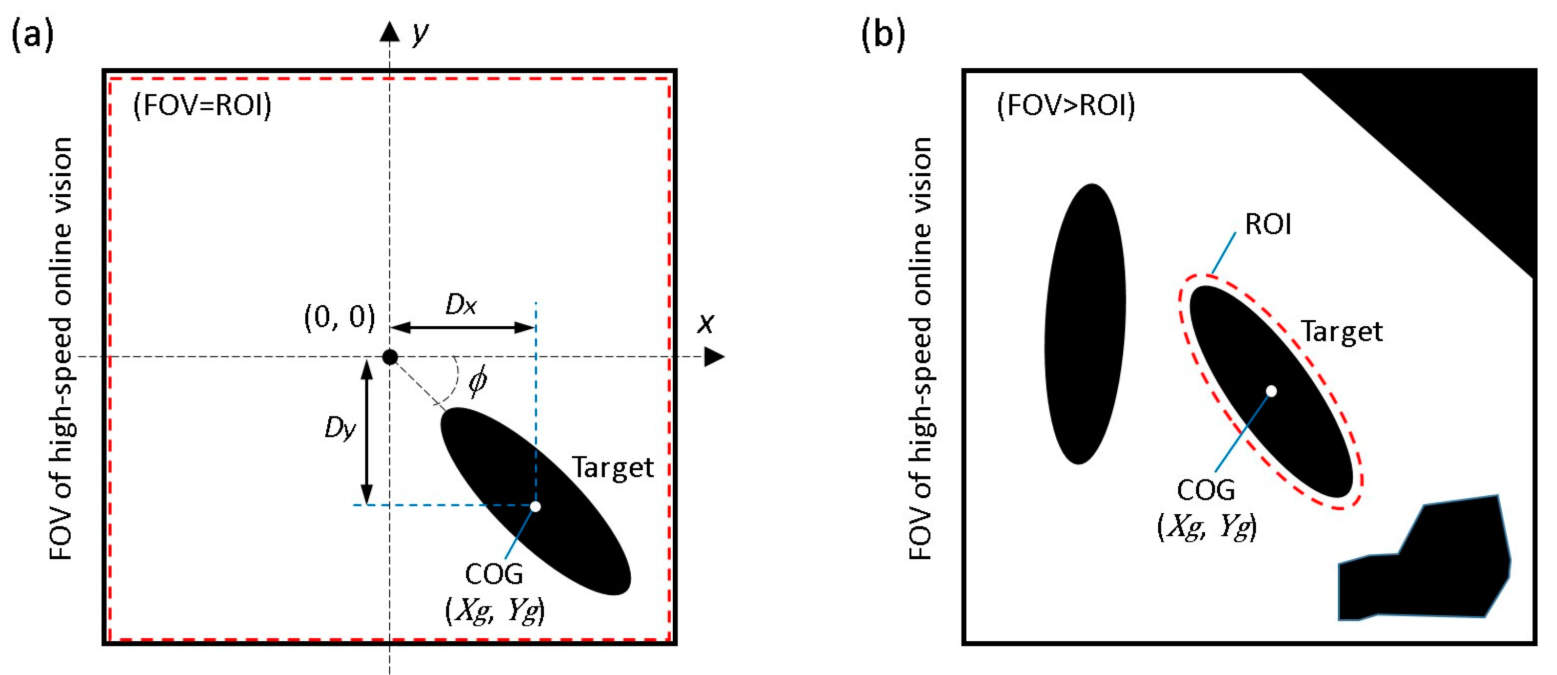
21] is used to adaptively change the threshold value to compensate for illumination variations in real time. The center of gravity (COG) of the target (
), as shown in
Figure 3a, can then be calculated from the 0th- and 1st-order moments of the binary image as follows:
where
represents the
i,j-order image moment,
,
represent the image COG coordinates, and
represents the pixel intensity at the index (
x,
y). In addition, the posture of the target
can be obtained from the 2nd-order moment,
Here, we suppose two main assumptions as follows; (i) because 3D movement of motile microorganisms is limited by a microfluidic chip, there is no overlap between each microorganism (no occlusion) during the observation; (ii) because the high-speed online vision sensor is used, the difference between each image frame is very small. Based on the assumptions above, specific procedures of the proposed visual tracking algorithm of a microorganism are shown in
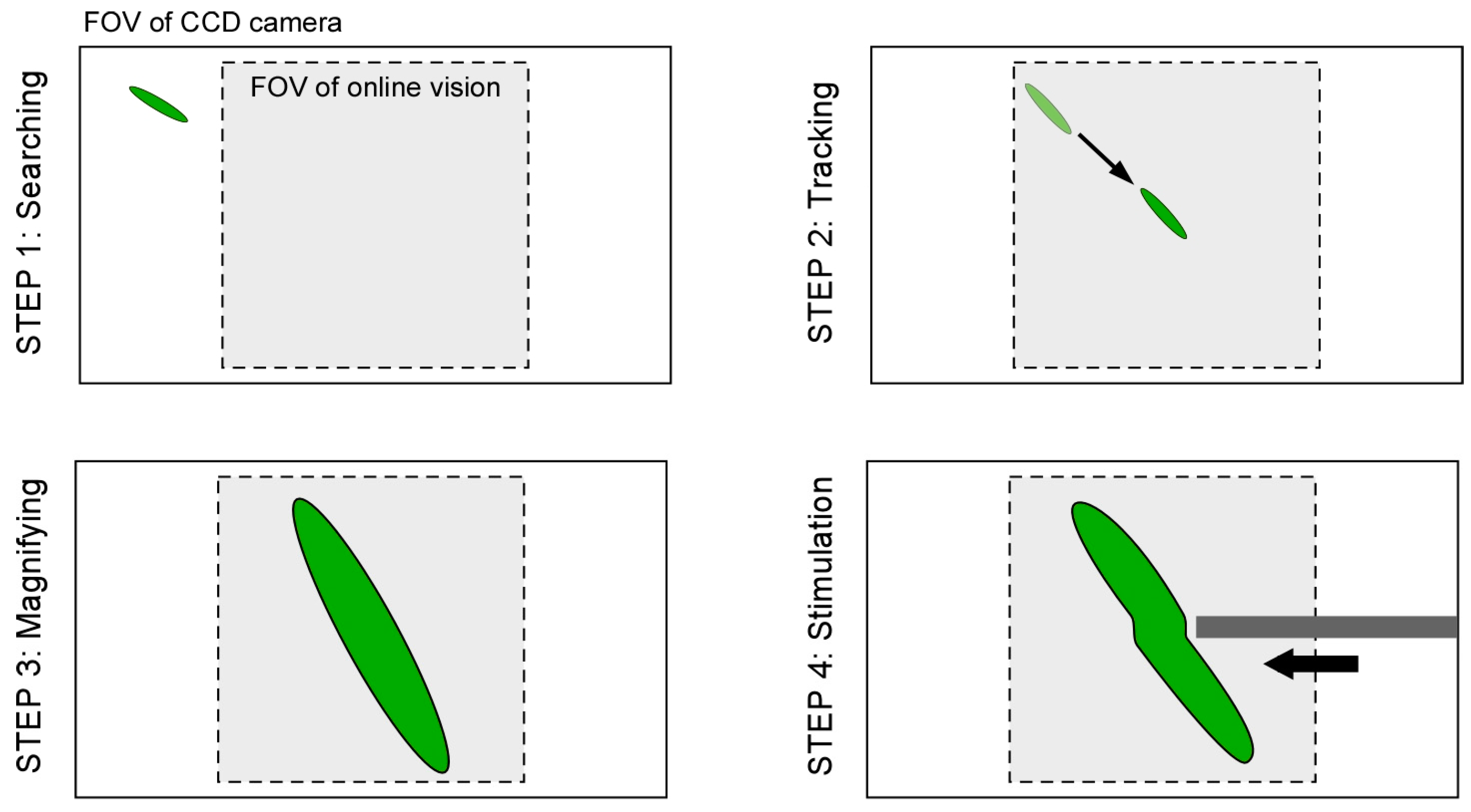
Figure 4.
Step 1: At first, by using the lowest magnification ratio of the microscope, the XY stage is moved with constant speed to find a microorganism as quickly as possible.
Step 2: If the vision finds the target (the total number of black pixels exceeds the threshold value), the visual tracking is started automatically. The XY stage is controlled such that the target’s position comes to the FOV center of the vision (x, y) = (0, 0).
Step 3: During the visual tracking, the magnification ratio of the microscope is seamlessly changed to obtain the enlarged view of the target by manually rotating the magnification dial. While increasing the magnification ratio, the pixel pitch, focal point, and light intensity are controlled in real time, as described in
Section 2.3. Therefore, the visual tracking is maintained continuously.
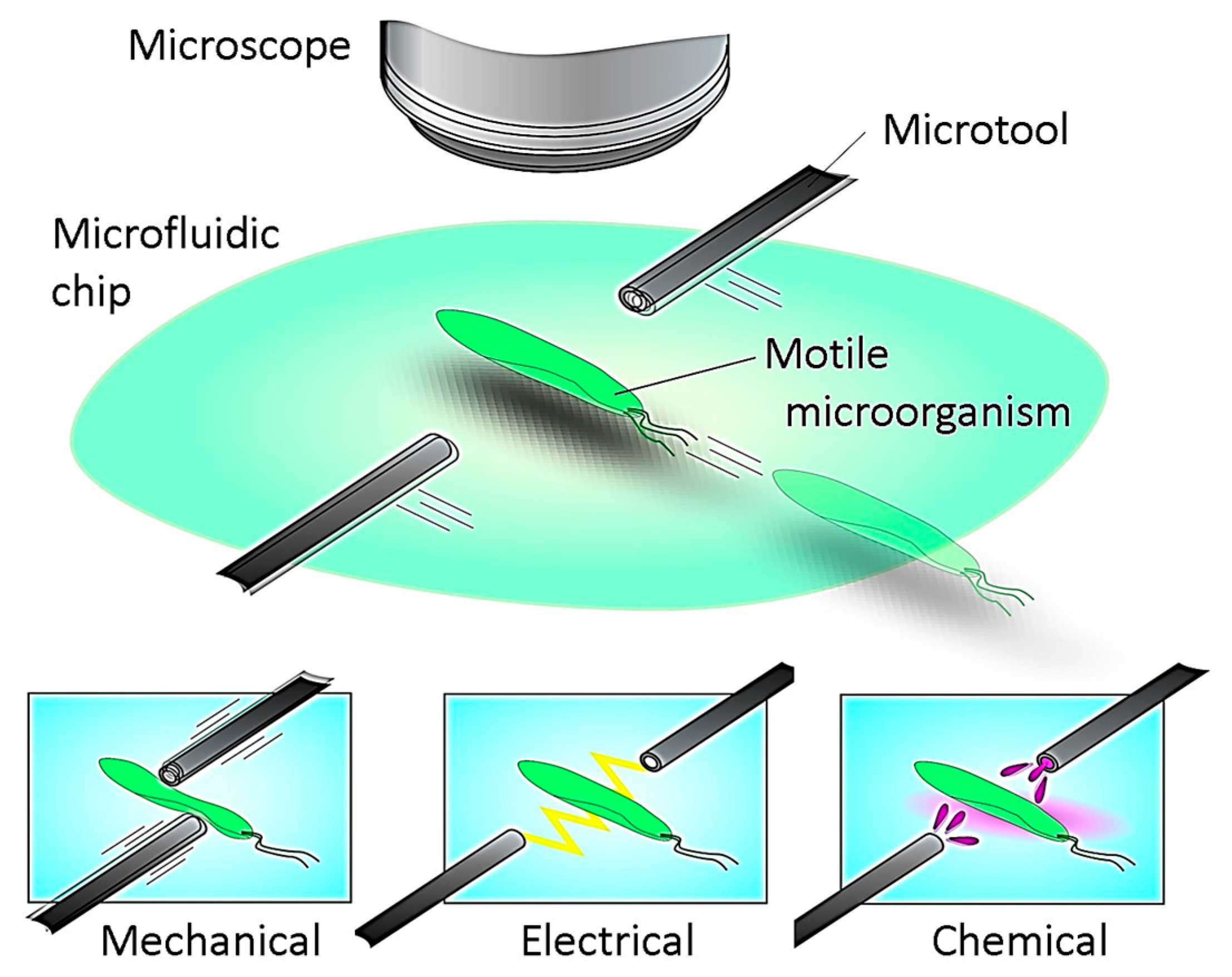
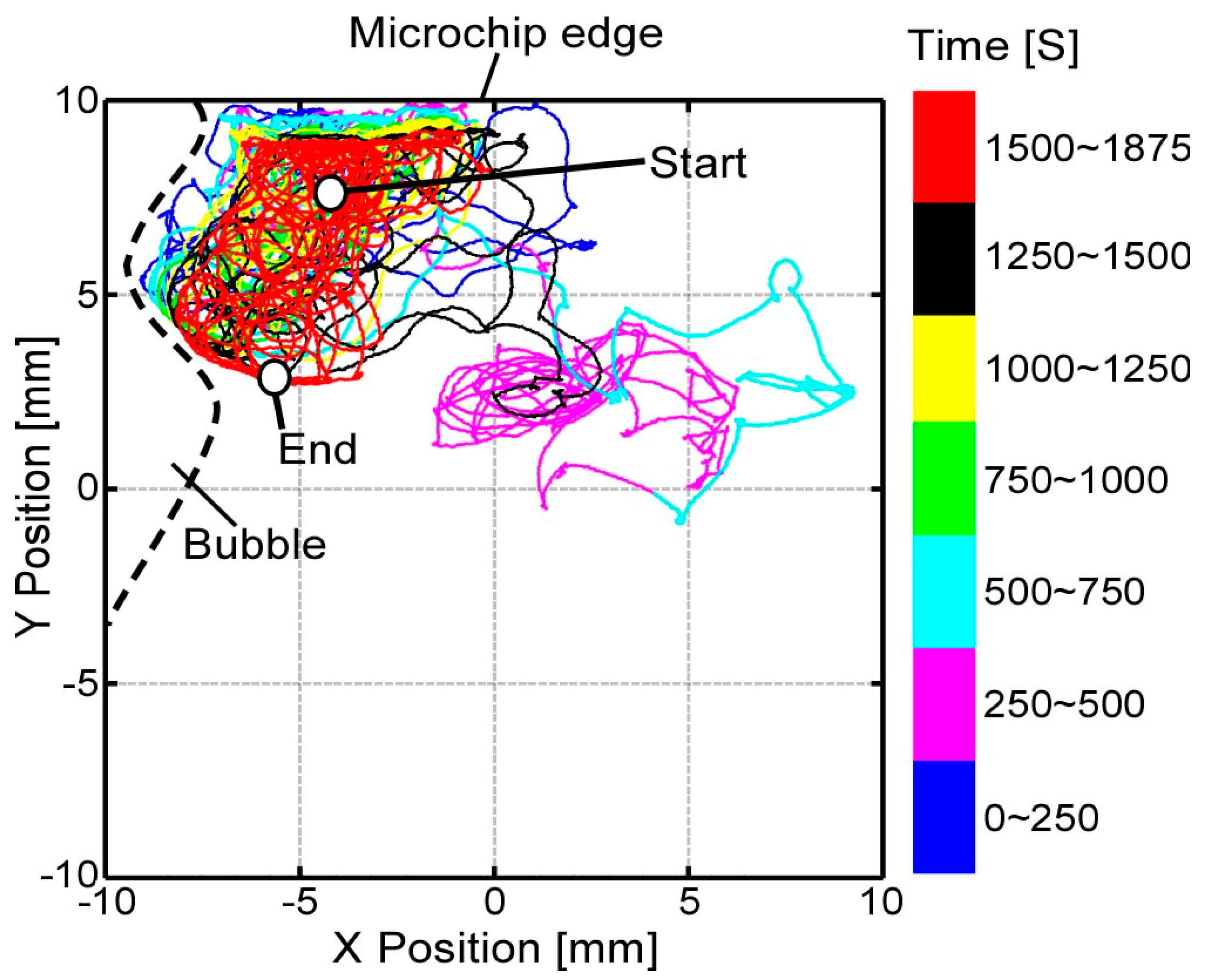
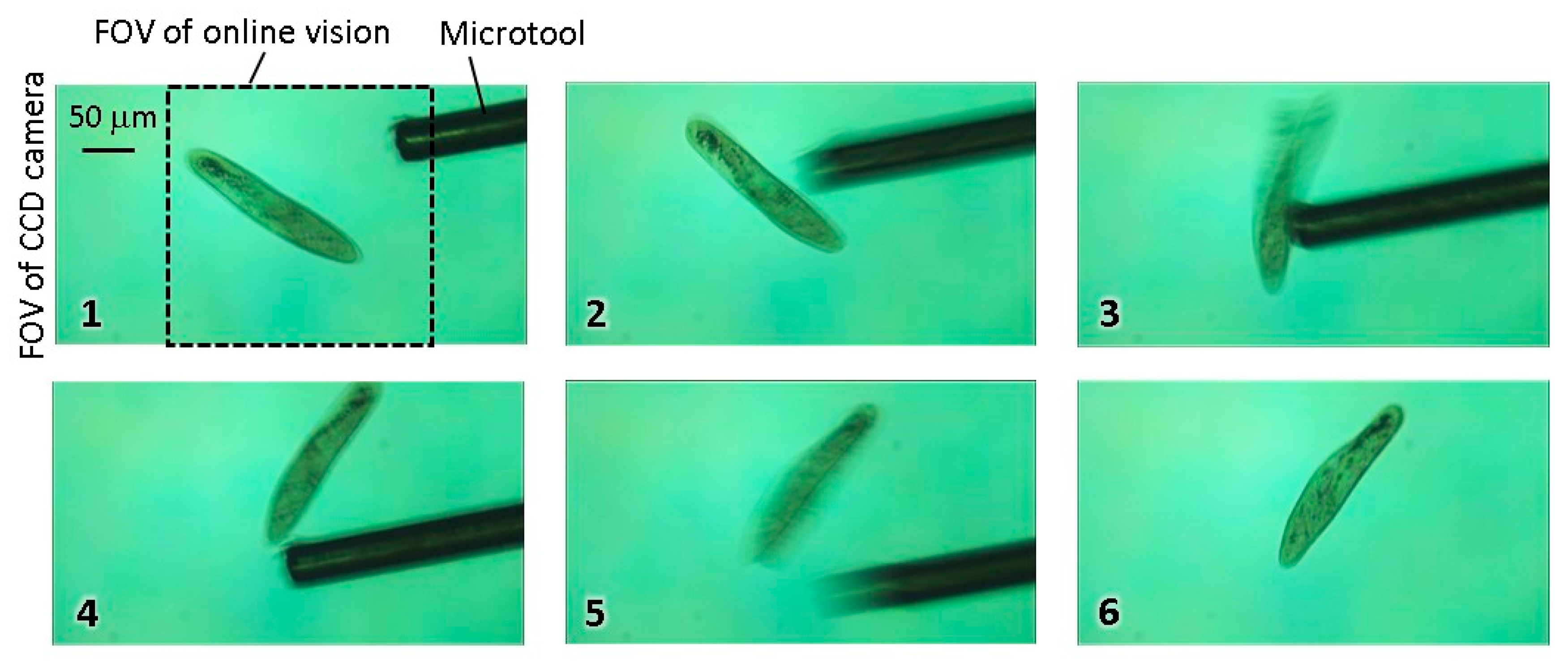
Step 4: During the tracking with the high magnification ratio of the microscope, local stimulation of target is conducted by inserting a microtool from the side space of the microfluidic chip. The specific behavior of the target is then recorded by using the high-resolution CCD camera.
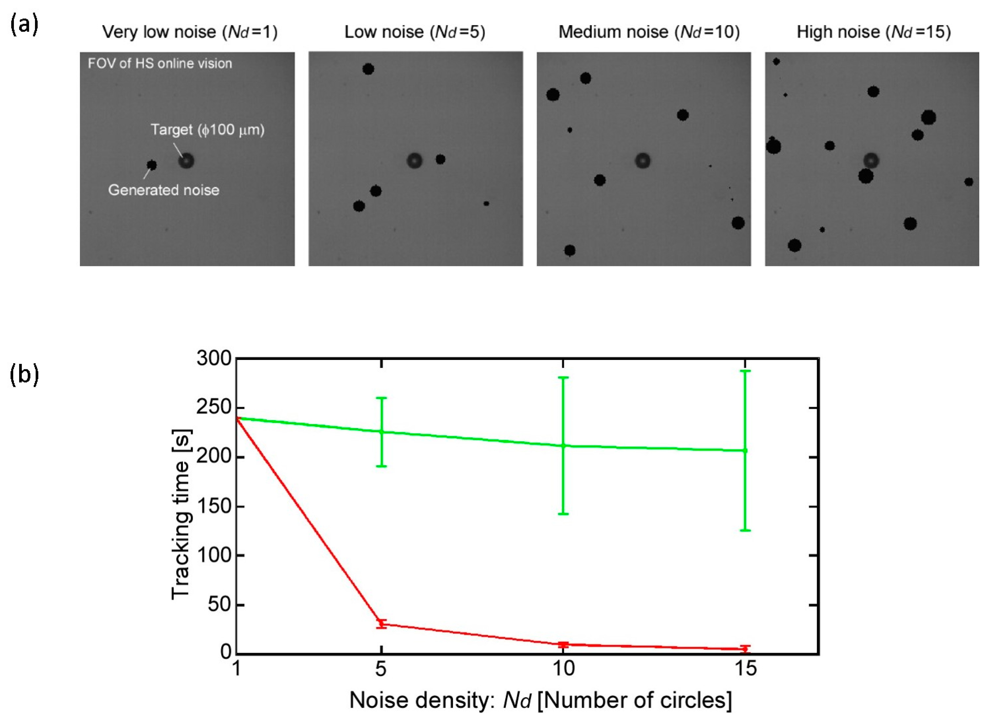
However, because there are many objects that can cause image noises in actual environments, it is quite difficult to track the target for a long time because the wrong position of the target COG is obtained. As a result, the visual tracking fails immediately, especially in the case of a highly magnified environment. In fact, a microfluidic chip includes significant debris and bubbles together with motile microorganisms, and the edge of the chip recognized as a darker area should be considered as image noise. Furthermore, when we attempt to apply stimulation to the target using the microtools, the calculated COG is moved from the target to the microtool, and the platform tracks the tool. This means that we cannot continue the observation of the target after the stimulation process. Although many effective algorithms to eliminate surrounding noise have been proposed and implemented in the field of image processing, the computing cost of their approaches is relatively high. To realize a high-speed tracking system, many images must be processed in real time, and the control thread must be maintained in the order of milliseconds by using a simple algorithm.
To overcome this dilemma, we introduce a simple visual tracking algorithm with high robustness by actively considering the characteristic of a high-speed online vision sensor. As described above, the difference between each frame is very small in high-frame-rate image capture, which contributes to simplify the image processing algorithm. In STEP 3, under the stable tracking and highly magnified condition, the region of interest (ROI) for image processing is shrunk to only around the target as shown in
Figure 3b. Here, the shape of the ROI at the
k-th image frame is determined as follows:
where
k − 1 means the target’s information in the previous frame, and
a and
b are the semimajor axis and the semiminor axis of the ellipse, respectively. Therefore, by using the previous frame’s information (COG and posture of the target) to determine the ROI for the current frame, we can reduce surrounding image noise and processing cost simultaneously. Although similar techniques have been used in other works with high-speed vision systems [
22,
23,
24], these systems did not have a magnification changing mechanism and did not focus on long-time target tracking.
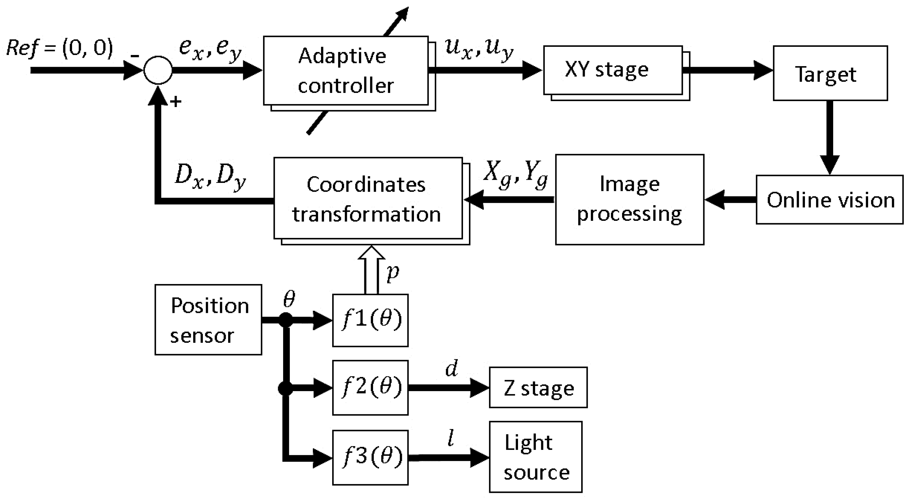
The complete block diagram of the platform is shown in
Figure 5. In the next section, the robustness of the implemented visual tracking algorithm with the magnification ratio control function is evaluated experimentally and applied to an actual motile microorganism. In these experiments, we are interested in testing the tracking system stability in the case of a noisy environment rather than the accuracy of tracking. This means that the tracking is considered successful if the tracking system is able to continuously track the target, even with a relatively large tracking error.

