Design and Analysis of the Elastic-Beam Delaying Mechanism in a Micro-Electro-Mechanical Systems Device

1
Key Laboratory of Space Utilization, Technology and Engineering Center for space Utilization, Chinese Academy of Sciences, Beijing 100094, China
2
Qian Xuesen Laboratory of Space Technology, NO. 104 Youyi Road, Haidian District, Beijing 100094, China
*
Author to whom correspondence should be addressed.
Micromachines 2018, 9(11), 567; https://doi.org/10.3390/mi9110567
Submission received: 17 October 2018
/
Revised: 31 October 2018
/
Accepted: 31 October 2018
/
Published: 2 November 2018
(This article belongs to the Special Issue MEMS Accelerometers)
Abstract
:The delaying mechanism is an important part of micro-electro-mechanical systems (MEMS) devices. However, very few mechanical delaying mechanisms are available. In this paper, an elastic-beam delaying mechanism has been proposed innovatively through establishing a three-dimensional model of an elastic-beam delay mechanism, establishing the force and the parameters of an elastic-beam delay mechanism, deriving the mathematical model according to the rigid dynamic mechanics theory, establishing the finite element model by using Ls-dyna solver of the Ansys software, and carrying out the centrifugal test. Simulation and test results match theoretical results quite well. It is believed that the elastic-beam delaying mechanism is quite effective and useful to slow the speed of the movable part in MEMS devices.
1. Introduction
The function of the delaying mechanism is to delay the appropriate time to ensure that the mechanism completes the corresponding action. The traditional delaying mechanism mainly includes the non-returning clock mechanism, the gas or liquid damping mechanism, the quasi-fluid mechanism, and so on [1,2].
Micro-electro-mechanical systems (MEMS) are a relatively new and fast-growing field in microelectronics. Micro-electro-mechanical systems are commonly used as actuators, sensors, and radio frequency and microfluidic components, as well as bio-composites, with a wide variety of applications in health care, automotive, and military industries. It is expected that the market for MEMS will grow to over $30 B by 2050 [3,4,5,6,7].
With the rapid development of MEMS technology, the demand for miniaturization of delaying mechanisms has become more urgent. At present, there are a large number of MEMS delaying mechanism research, which are mainly divided into two categories. One category is the delaying mechanism based on electricity [8,9,10,11,12,13,14,15,16], which has high-control precision; Dalian University of Technology in China has studied the v-shaped micro-electric-thermal delaying mechanism based on MEMS technology [8], and the university of Toulouse in France has studied MEMS electro-powder delaying mechanism [9]. The other category is the mechanical delaying mechanism [17]; KAMAN INC. of the United States demonstrated a MEMS mechanical delaying mechanism and its delay action does not require electronic control, and it is free from electromagnetic interference and high reliability, and it is particularly suitable for battlefield use in complex electromagnetic environments.
In this paper, the MEMS Safety and Arming (S&A) system used in small-caliber ammunition is proposed innovatively, and the concrete structure as shown in Figure 1. The size of the MEMS S&A system is 10 mm × 13 mm × 0.5 mm. The MEMS S&A system is composed of threshold-value judging mechanism, lock-releasing mechanism, elastic-beam delaying mechanism, centrifugal lock, setback lock, sub-centrifugal slider, and main centrifugal slider. It has two functions [18,19,20,21,22,23,24,25,26,27,28]: one function is that after the ammunition goes out of the antiaircraft gun, it needs a certain time delay to ensure that the main centrifugal slider does not move to the designated position, so as to ensure that the ammunition does not explode at the muzzle or launch area, which can guarantee the safety of the ammunition. The other function is that when ammunition arrives at the designated area, it needs the main centrifugal slider to move to the designated position to ensure the reliable function of ammunition. The elastic-beam delaying mechanism plays an important role in ensuring the safety of ammunition. Figure 2 shows that the elastic-beam delaying mechanism is composed of baseplate, centrifugal slider, passive tooth, active tooth, and threshold elastic beam, which can slow the speed of the movable part to ensure a proper delay time and guarantee the safety of the ammunition.
2. Model and Theoretical Analysis
2.1. Model
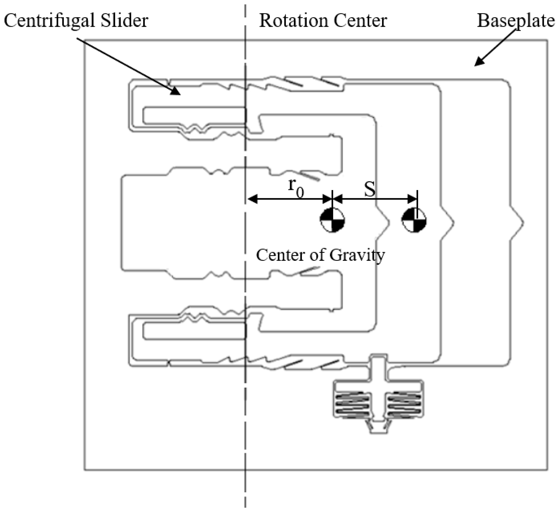
The center of gravity, rotation center, and stroke of the sub-centrifugal slider are shown in Figure 3. The parameters of elastic-beam delaying mechanism are shown in Figure 4. The force of elastic-beam delaying mechanism are shown in Figure 5. Based on Figure 4, the main variables are parameterized, shown as Table 1.
2.2. Force Analysis
We have some hypotheses:
- Neglecting the factors such as friction and air resistance;
- The process of active tooth contact passive tooth movement is from uniform acceleration to uniform deceleration.
According to the Figure 4 and Figure 5, we can get the centrifugal force of centrifugal slider
where, m is the mass of centrifugal slider; r is the eccentricity of centrifugal slider; n is the rotating speed of projectile.
According to the Figure 4 and Figure 5b, we can get
where, is the pressure of the active tooth to the passive tooth; is the friction coefficient of the active tooth to the passive tooth; f is the friction of the active tooth to the passive tooth; , , , is the decomposition for of and f.
So, we can get the force of the centrifugal slider in the X and Y direction
2.3. Deflection Calculation
According to the cantilever deflection equation of applied engineering mechanics, the Figure 6 can be obtained.
According to the Figure 6, we can get the deflection
If in (4), the maximum value of can be obtained
According to the (5)–(7), the maximum deflection at node C can be obtain.
Combined with Figure 4, the stroke of the centrifugal slider can be obtained
2.4. Kinematic Analysis and Time Estimating
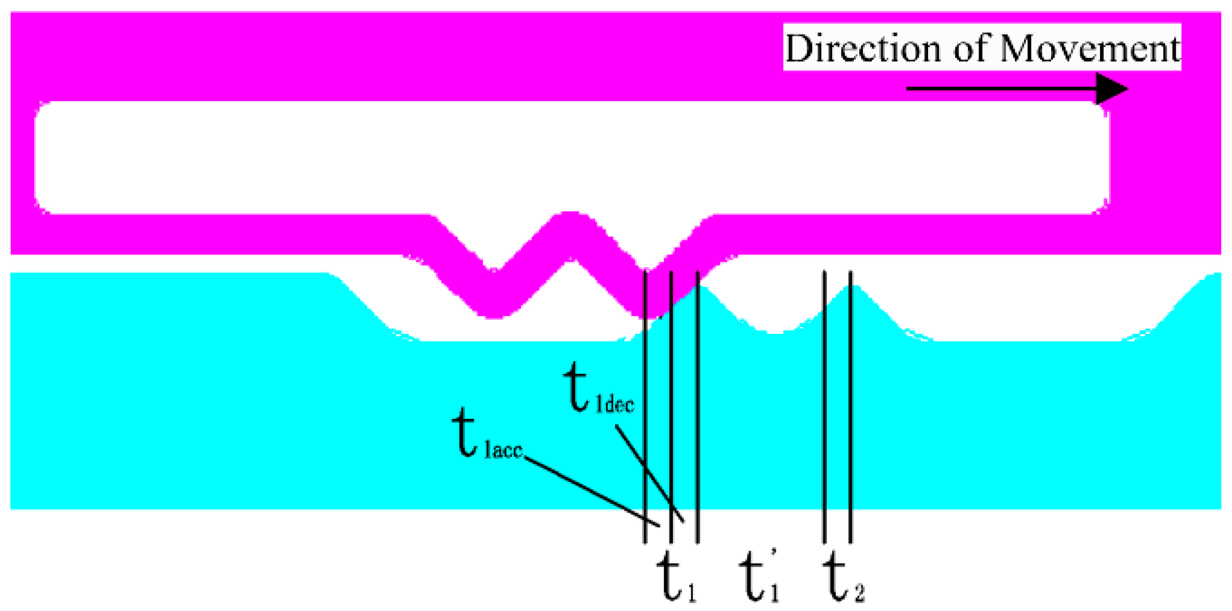
The schematic diagram of kinematic analysis and time estimating are shown in Figure 7.
2.4.1. The First Contact of Active Tooth to Passive Tooth
The first contact is divided into two stages, one stage (t1acc) is the uniformly acceleration process when the active tooth from the initial position to the first contact; the other stage (t1dec) is the uniform deceleration process when the active tooth from the first contact to separation.
And
where, S is the displacement of the active tooth; v0 is the initial velocity of the active tooth; a is the average acceleration of the active tooth; t is the time of the whole movement process.
• The uniformly acceleration process
We can get
where, v1 is the initial velocity of the active tooth at first contact; a1 is the average acceleration of the active tooth at first contact; S1 is the displacement of the active tooth from the initial position to the first contact.
So
where, r0 is the initial eccentricity of centrifugal slider.
• The uniformly deceleration process
The uniform deceleration process is the inverse of the uniform acceleration process.
So
2.4.2. The Second Contact of Active Tooth to Passive Tooth
The second contact is divided into two stages, one stage (t1’) is the uniformly acceleration process when the active tooth from separation to second contact; other stage (t2) is the uniform deceleration process when the active tooth from the second contact to separation.
• The uniformly acceleration process
We can get
where, v1’ is the velocity of the active tooth separation from the first passive tooth; a1’ is the average acceleration of the active tooth from separation to second contact; v2 is the velocity of the active tooth at second contact
So
• The uniformly deceleration process
The uniform deceleration process is the inverse of the uniform acceleration process.
We can get
where, a2 is the average acceleration of the active tooth the second contact to separation.
So
According to the (14), (16), and (17), we can get the time t2.
According to the above theoretical analysis, the maximum deflection and time estimating of the different parameterized variable can be obtained, shown as Table 2.
3. Simulation Analysis
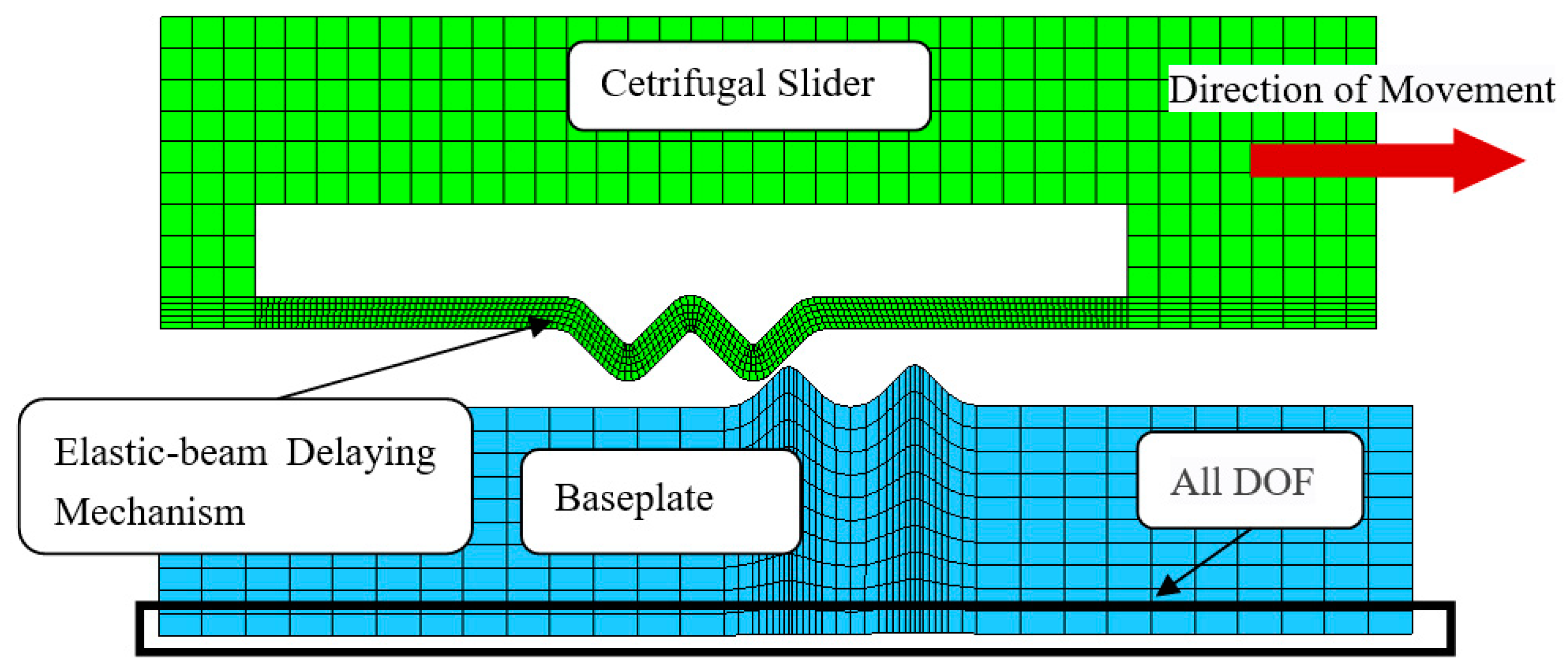
Base on the Figure 4 and Table 1, establishing the infinite model of elastic-beam delaying mechanism (Figure 8) by using HyperMesh, applying Material properties (Table 3), loading the acceleration of a constant 30,000 g, and making nonlinear dynamic mechanics simulation by using ANSYS/LS-DYNA, displacement-time curves (Figure 9a) and velocity-time curves (Figure 9b) are obtained.
The Table 4 shown that the simulation results of the deflection are in good agreement with the theoretical results, and the maximum error is less than 6.5%, because of the residual velocity of separation between active teeth and passive when simulating.
- In terms of movement trend, the simulation results are in good agreement with the theoretical calculation;
- In terms of the movement time for the same displacement, simulation results are shorter than the theoretical calculation. Because when active tooth is separated from the first passive tooth, the simulation results have residual velocity, and the theoretical value is 0;
- The gap between active tooth and passive tooth is the most important factor affecting the movement time.
4. Fabrication
The Figure 10 shows the micromachining process of silicon-based MEMS S&A system. It mainly includes the silicon-based MEMS S&A system in the middle and Benzocyclobutene (BCB) bonded glass on the upper and lower sides. As shown in Figure 11, the white part is the structure area, which is the main structure left by photolithography with bulk-micromachining technology, the blue part is the hollow area, the green part is the silicon-glass bonding area with BCB bonding, which enables the structure area to generate a certain gap, so that the key structure can move along the predetermined mode in the hollow area.
5. Test
There are two kinds of tests for delaying mechanism:
Four groups of centrifugal tests were carried out on the parameterized delaying mechanism, as shown in Table 1. The theoretical and simulation results obtained from Formula (8) were combined with centrifugal test to obtain Table 5 and Figure 17.
- The g-value of the delaying mechanism with the same processing batch and the same parameter is relatively discrete, indicating that the material properties of silicon have a certain degree of dispersion.
- The theoretical results are all higher than the simulation results, because the theoretical calculation is completely static, and the possible initial velocity is ignored. And the average value of the test results is higher than the theoretical results, because of the friction and gas resistance in the micro-sample.
- Theoretical results, simulation results and test results have a high degree of agreement, which can be used for initial optimization design.
6. Conclusions
In this paper, the elastic-beam delaying mechanism has been proposed innovatively. Combining with the rigid dynamic mechanics theory, the mathematical model was established. Simulation and test results match theoretical results quite well. It is believed that the elastic-beam delaying mechanism is quite effective and useful to slow the speed of the movable part in MEMS devices.
Author Contributions
F.W. and L.Z. conceived the problem and designed the solution; F.W. and L.L. designed and performed the experiments; Z.Q., Q.C. and F.W. analyzed the data; F.W. wrote the paper.
Acknowledgments
The research was supported by Key Laboratory of Space Utilization, and sponsored by the National Project of China (Y7140211XN).
Conflicts of Interest
The authors declare no conflict of interest.
References
- Ma, B.H. Fuze Structure and Function; National Defense Industry Press: Beijing, China, 1984. [Google Scholar]
- Wang, S.Y. Fuze System Analysis and Engineering Design Questions and Solutions; Nanjing University of Science and Technology: Nanjing, China, 2005. [Google Scholar]
- Shaeffer, D.K. MEMS inertial sensors: A tutorial overview. IEEE Commun. Mag. 2013, 51, 100–109. [Google Scholar] [CrossRef]
- Allameh, S.M. An introduction to mechanical-properties-related issues in MEMS structures. J. Mater. Sci. 2003, 38, 4115–4123. [Google Scholar] [CrossRef]
- Robinson, C.H.; Hoang, T.Q.; Gelak, M.R. Materials, Fabrication and Assembly Technologies for Advanced MEMS-based Safety and Arming Mechanism for Projectile Munitions; J. F. Rasmussen Axsun Technologies, Inc.: Billerica, MA, USA, 2006. [Google Scholar]
- Zhou, X.; Shan, T.; Qi, X. Analysis and design of a high-power laser interrupter for MEMS based safety and arming systems. Microsyst. Technol. 2017, 23, 1–10. [Google Scholar] [CrossRef]
- Wang, D.K.; Lou, W.Z.; Feng, Y.; Zhang, X.Z. Design of High-Reliability Micro Safety and Arming Devices for a Small Caliber Projectile. Micromachines 2017, 8, 234. [Google Scholar] [CrossRef]
- Zhang, R.; Chu, J.K.; Wang, H.Y.; Chen, Z.P. SU-8 chevron electrothermal micro-actuator with three-layer structures. Optics Precis. Eng. 2012, 7, 1500–1508. [Google Scholar] [CrossRef]
- Hélène, P.; Carole, R.; Marjorie, S.; Fabrice, M.; Xavier, D. Integration of a MEMS based safe arm and fire device. Sensors Actuat. A Phys. 2010, 159, 157–167. [Google Scholar]
- Cope, R.D. MEMS S-A Technology; Naval Air Warfare Center, Weapons Division: China Lake, CA, USA, 1999. [Google Scholar]
- Li, X.; Zhao, Y.; Hu, T. Design of a large displacement thermal actuator with a cascaded V-beam amplification for MEMS safety-and-arming devices. Microsyst. Technol. 2015, 21, 2367–2374. [Google Scholar] [CrossRef]
- Zhao, Y.L.; Hu, T.J.; Li, X.Y. Design and characterization of a large displacement electro-thermal actuator for a new kind of safety-and-arming device. Energy Harvest. Syst. 2015, 2, 143–148. [Google Scholar] [CrossRef]
- Yang, J.; Gao, J.Z.; Liu, Y.L.; Jiang, Z.D. Design and Fabrication of MEMS-Based Thermal Micro-Actuator. Micronanoelectron. Technol. 2005, 4, 175–179. [Google Scholar]
- Fogel, O.; Winter, S.; Benjamin, E. 3D printing of functional metallic microstructures and its implementation in electrothermal actuators. Addit. Manuf. 2018, 21, 207–311. [Google Scholar] [CrossRef]
- Kandula, P.; Dong, L. Robust Voltage Control for an Electrostatic Micro-Actuator. J. Dyn. Sys. Meas. Control. 2017, 140, 061012. [Google Scholar] [CrossRef]
- Dong, L.; Kandula, P.; Gao, Z.; Wang, D. Active disturbance rejection control for an electric power assist steering system. Int. J. Intell. Control Syst. 2010, 15, 18–24. [Google Scholar]
- Pezous, H.; Rossi, C.; Sanchez, M. Fabrication, assembly and tests of a MEMS-based safe, arm and fire device. J. Phys. Chem. Solids 2010, 71, 75–79. [Google Scholar] [CrossRef]
- Robinson, C.H.; Wood, R.H. Ultra-Miniature Electro-Mechanical Safety and Arming Device. U.S. Patent 8,276,515, 2 October 2012. [Google Scholar]
- Robert, R. MEMS Based Fuse Technology. In Proceedings of the 58th Annual NDIA Fuse Conference, Baltimore, MD, USA, 7–9 July 2015. [Google Scholar]
- Wang, Y.; Lou, W.Z.; Feng, Y. High impact dynamic simulation of planar S-form micro-spring. Key Eng. Mater. 2013, 562, 1107–1110. [Google Scholar] [CrossRef]
- Tabata, O.; Tsuchiya, T. Reliability of MEMS; Southeast University Press: Nanjing, Jiangsu, China, 2009. [Google Scholar]
- Perrin, M. New Generation Naval Artillery Multi-Function Fuse. In Proceedings of the NDIA’s 56th Annual Fuse Conference, Baltimore, MD, USA, 14–16 May 2012. [Google Scholar]
- Zhou, Z.J.; Nie, W.R.; Wan, X.F. Study on parameters of MEMS planar zigzag slot for fuse. Key Eng. Mater. 2014, 609, 813–818. [Google Scholar]
- Lyle, H.J. Precision Guidance Kit (PGK). In Proceedings of the NDIA 56th Annual Fuse Conference, Baltimore, MD, USA, 14–16 May 2012. [Google Scholar]
- He, G. Micro-Mechanical Safety Mechanism Based on MEMS Technology Theory and Application. Ph.D. Thesis, Beijing Institute of Technology, Beijing, China, 2006. [Google Scholar]
- Li, X.; Zhao, Y.; Hu, T. Design of a high-speed electrothermal linear micromotor for microelectromechanical systems safety-and-arming devices. Micro Nano Lett. 2016, 11, 692–696. [Google Scholar] [CrossRef]
- Liu, J.K.; Qi, X.L.; Jia, J. Study on the reliability problem of MEMS fuse mechanism. Adv. Mater. Res. 2012, 628, 72–77. [Google Scholar] [CrossRef]
- Renaud, L. Pyro-MEMS Technological breakthrough in fuse domain. In Proceedings of the NDIA 55th Annual Fuse Conference, Salt Lake City, UT, USA, 24–26 May 2011. [Google Scholar]
Figure 1.
The mechanical MEMS S&A system.

Figure 2.
The elastic-beam delaying mechanism.

Figure 3.
The center of gravity, rotation center, and stroke of the centrifugal slider.

Figure 4.
The parameters of elastic-beam delaying mechanism.

Figure 5.
The force of elastic-beam delaying mechanism: (a) overall view, (b) decomposition view.

Figure 6.
The schematic diagram of elastic-beam deflection analysis.

Figure 7.
The schematic diagram of kinematic analysis and time estimating.

Figure 8.
The infinite model of elastic-beam delaying mechanism.

Figure 9.
The simulation results of different structural parameters (a) displacement-time curves (b) velocity -time curves.
Figure 9.
The simulation results of different structural parameters (a) displacement-time curves (b) velocity -time curves.

Figure 10.
Micromachining process of silicon-based MEMS S&A system (a) Back-up; (b) Physical Vapor Deposition (PVD) Al 2um; (c) PVD Al 0.2um; (d) Structural lithography; (e) Corroded aluminum; (f) Deep Reactive Ion Etching (DRIE); (g) Degumming; (h) Back-up; (i) BCB Lithography; (j) BCB bond; (k) Buck-up; (l) BCB Lithography; (m) BCB bond; (n) Scribing.

Figure 11.
The processing layout (a) MEMS S&A system, (b) Elastic-beam delaying mechanism.

Figure 12.
The micro-sample of the elastic-beam delaying mechanism (a) overall view, (b) partial view.
Figure 12.
The micro-sample of the elastic-beam delaying mechanism (a) overall view, (b) partial view.

Figure 13.
Impact test platform.

Figure 14.
The direction of impact acceleration.

Figure 15.
Centrifugal test platform and centrifugal adapter.

Figure 16.
The direction of centrifugal acceleration.

Figure 17.
The g-value of the delaying mechanism with different parameters.


Table 1.
The parameters of elastic-beam delaying mechanism.
| Number | 1 | 2 | 3 | 4 | 5 |
|---|---|---|---|---|---|
| Width of the elastic-beam B/mm | 0.1 | 0.08 | 0.1 | 0.1 | 0.1 |
| Angle of active tooth α/° | 90 | 90 | 70 | 90 | 90 |
| Length of the elastic-beam L/mm | 1.2 | 1.2 | 1.2 | 2.4 | 1.4 |
| Gap between active and tooth and passive tooth E/mm | 0.03 | 0.03 | 0.02 | 0.03 | 0.03 |
| Number of the active tooth | 2 | 1 | |||
| Distance between two adjacent active teeth L′/mm | 0.4 | - | |||
| Distance between two adjacent passive teeth L″/mm | 0.4 | ||||
Table 2.
The theoretical result of maximum deflection and time estimating.
| Number | 1 | 2 | 3 | 4 | 5 | |
|---|---|---|---|---|---|---|
| Mass of centrifugal slider m/kg | 2.88 × 10⁻⁶ | 2.836 × 10⁻⁶ | 2.866 × 10⁻⁶ | 2.84 × 10⁻⁶ | 2.868 × 10⁻⁶ | |
| Maximum deflection wmax/mm | 2.86 × 10⁻² | 5.50 × 10⁻² | 2.0 × 10⁻² | 0.20 | 3.23 × 10⁻² | |
| Time estimating/μs | t1 | 27.6 | 28.3 | 23.1 | 73.0 | 29.3 |
| t1′ | 49.7 | 48.0 | 50.3 | 36.5 | 49.5 | |
| t2 | 1.9 | 3.8 | 1.3 | 18.3 | 2.2 | |
| ttotal | 79.2 | 80.1 | 74.7 | 129.8 | 81 | |
Table 3.
The material properties [21].
Table 3.
The material properties [21].
| Name | Density (kg/m3) | Elasticity Modulus E (GPa) | Poisson’s Ratio |
|---|---|---|---|
| Si | 2.3 × 10³ | 180 | 0.3 |
Table 4.
The maximum deformation and error between theoretical results and simulation results.
| Number | 1 | 2 | 3 | 4 | 5 | |
|---|---|---|---|---|---|---|
| Maximum deflection wmax/mm | Theoretical | 2.86 × 10⁻² | 5.50 × 10⁻² | 2.0 × 10⁻² | 0.20 | 3.23 × 10⁻² |
| Simulation | 2.92 × 10⁻² | 5.64 × 10⁻² | 2.1 × 10⁻² | 0.213 | 3.37 × 10⁻² | |
| Error (Simulation-Theoretical)/Theoretical | 2.1% | 2.5% | 5.0% | 6.5% | 4.3% | |
Table 5.
The g-value of the delaying mechanism with different parameters.
| Number | Test Results/g | Theoretical Results/g | Simulation Results/g | ||||
|---|---|---|---|---|---|---|---|
| Group 1 | Group 2 | Group 3 | Group 4 | Average | |||
| (1) | 35,000 | 33,000 | 35,000 | 36,000 | 34,750 | 31,500 | 30,000 |
| (2) | 19,000 | 15,000 | 21000 | 22,000 | 19,250 | 16,370 | 15,000 |
| (3) | 33,000 | 31,000 | 34,000 | 36,000 | 33,500 | 30,120 | 28,000 |
| (4) | 9000 | 7000 | 10,000 | 9000 | 8750 | 4520 | 4100 |
| (5) | 24,000 | 22,000 | 24,000 | 26,000 | 24,000 | 20,500 | 19,000 |
© 2018 by the authors. Licensee MDPI, Basel, Switzerland. This article is an open access article distributed under the terms and conditions of the Creative Commons Attribution (CC BY) license (http://creativecommons.org/licenses/by/4.0/).
Share and Cite
MDPI and ACS Style
Wang, F.; Zhang, L.; Li, L.; Qiao, Z.; Cao, Q. Design and Analysis of the Elastic-Beam Delaying Mechanism in a Micro-Electro-Mechanical Systems Device. Micromachines 2018, 9, 567. https://doi.org/10.3390/mi9110567
AMA Style
Wang F, Zhang L, Li L, Qiao Z, Cao Q. Design and Analysis of the Elastic-Beam Delaying Mechanism in a Micro-Electro-Mechanical Systems Device. Micromachines. 2018; 9(11):567. https://doi.org/10.3390/mi9110567
Chicago/Turabian StyleWang, Fufu, Lu Zhang, Long Li, Zhihong Qiao, and Qian Cao. 2018. "Design and Analysis of the Elastic-Beam Delaying Mechanism in a Micro-Electro-Mechanical Systems Device" Micromachines 9, no. 11: 567. https://doi.org/10.3390/mi9110567
Note that from the first issue of 2016, this journal uses article numbers instead of page numbers. See further details here.