Topology Optimization of Spatially Compliant Mechanisms with an Isomorphic Matrix of a 3-UPC Type Parallel Prototype Manipulator


1
School of Mechanical and Electrical Engineering, Guangzhou University, Guangzhou 510006, China
2
Department of Mechatronic Engineering, Shantou University, Shantou 515063, China
*
Author to whom correspondence should be addressed.
Micromachines 2018, 9(4), 184; https://doi.org/10.3390/mi9040184
Submission received: 25 February 2018
/
Revised: 9 April 2018
/
Accepted: 11 April 2018
/
Published: 14 April 2018
Abstract
:A novel topology optimization approach is proposed in this paper for the design of three rotational degree-of-freedom (DOF) spatially compliant mechanisms, combining the Jacobian isomorphic mapping matrix with the solid isotropic material with penalization (SIMP) topological method. In this approach, the isomorphic Jacobian matrix of a 3-UPC (U: universal joint, P: prismatic joint, C: cylindrical joint) type parallel prototype manipulator is formulated. Subsequently, the orthogonal triangular decomposition and differential kinematic method is applied to uncouple the Jacobian matrix to construct a constraint for topology optimization. Firstly, with respect to the 3-UPC type parallel prototype manipulator, the Jacobian matrix is derived to map the inputs and outputs to be used for initializing the topology optimization process. Secondly, the orthogonal triangular decomposition with the differential kinematic method is used to reconstruct the uncoupled mapping matrix to derive the 3-UPC type parallel prototype manipulator. Finally, a combination of the solid isotropic material with penalization (SIMP) method and the isomorphic mapping matrix is applied to construct the topological model. A typical three rotational DOF spatially compliant mechanism is reported as a numerical example to demonstrate the effectiveness of the proposed method.
1. Introduction
Compliant mechanisms are widely used in precision manufacturing as they do not show problems such as clearance, friction and wear [1]. In the past two decades, flexible hinges have been replacing the rigid hinges in parallel mechanism configurations, and the pseudo rigid body method has been used to build flexible or compliant mechanism models [2,3,4]. However, the whole structural stiffness maximization is not satisfied by this method, while compliant mechanisms are limited in use to micro positioning due to their spatial multi-DOF (degree-of-freedom) motion characteristics [5,6,7]. Recently, flexible beam structures and flexure joints are used to overcome these issues [8,9,10,11], such as Tan et al. [12], who proposed a multi-leaf configuration of expanded-motion-range flexure hinges.
Previous works [13,14,15,16] highlighted how research into compliant mechanisms is divided into two main directions: large stroke with multi-DOF and micro/nano scale displacement with multi-DOF. The latter scope is further divided into lumped compliance (often referred to as the pseudo-rigid-body-model, PRBM) and distributed compliance (often referred to as topology optimization), as reported in [17]. This paper focuses on topology optimization.
Considering the multi-DOF motion characteristics of parallel manipulators, the hinge-replacing method is used to reconstruct the spatially compliant mechanism. Examples can be found in the 6-DOF compliant parallel mechanisms designed by Hudgens et al. [18] and Mclnroy et al. [19] and in the three-DOF planar-compliant parallel mechanisms proposed by Yi et al. [20] and Hao et al. [21]. The model of compliant mechanisms with flexure joints can be built by using the pseudo-rigid-body approach in contrast to the original structure of parallel manipulators. To improve the overall stiffness of compliant mechanisms, the topology optimization approach has been used for its design. For example, Sigmund [22,23,24] developed the density method based on the continuum-type topology optimization technique for the optimal design of compliant mechanisms. Using the mutual energy approach, the homogenization method is adopted by Nishiwaki [25] to solve compliant mechanism optimization problems, and Saxena [26] generalized multi-criteria formulations for the performance improvement of output deformation and strain energy computation. According to the stiffness of elements, Wang [27] proposed a linear elastic structural analysis method. Large displacement, multiple materials, and 3D topology optimization methods for compliant mechanisms are proposed in [28,29,30].
In hingeless topological structures, the pseudo-rigid-body method is not suitable for modeling, because there is no exact rigid mechanism corresponding to the topological structure, moreover, the error related to flexible elements is reported in the literature [31,32,33]. To overcome this shortcoming, the Jacobian matrix of spatial multi-DOF parallel manipulators may be considered during the topology optimization process. The Jacobian matrix is the mapping relationship between the operation space and the joint space, and it is only concerned with structural parameters. A Jacobian matrix based on a compliance frame is adopted in [34,35], and a planar-compliant mechanism is proposed. However, the compliance frame is changed during topology optimization process, thus it cannot be used to model the topological structure of the proposed planar-compliant mechanism. In this paper, a novel topology optimization method for a three-DOF spatially compliant mechanism is proposed by combining the Jacobian isomorphic mapping matrix with solid isotropic material with penalization (SIMP) topology optimization method.
The paper is organized as follows. By using the differential approximation method, the Jacobian isomorphic mapping matrix of the 3-UPC (U: universal joint, P: prismatic joint, C: cylindrical joint) type parallel prototype manipulator is calculated in Section 2. Section 3 reports the Jacobian isomorphic mapping matrix combination with SIMP, along with the topological model of spatial compliant mechanism with three rotational DOF. The sensitivities analysis and topological structure derivation are described in Section 4. Experimental investigations are shown in Section 5. Concluding remarks are summarized in Section 6.
2. Isomorphic Mapping Matrix of the 3-UPC Type Parallel Prototype Manipulator
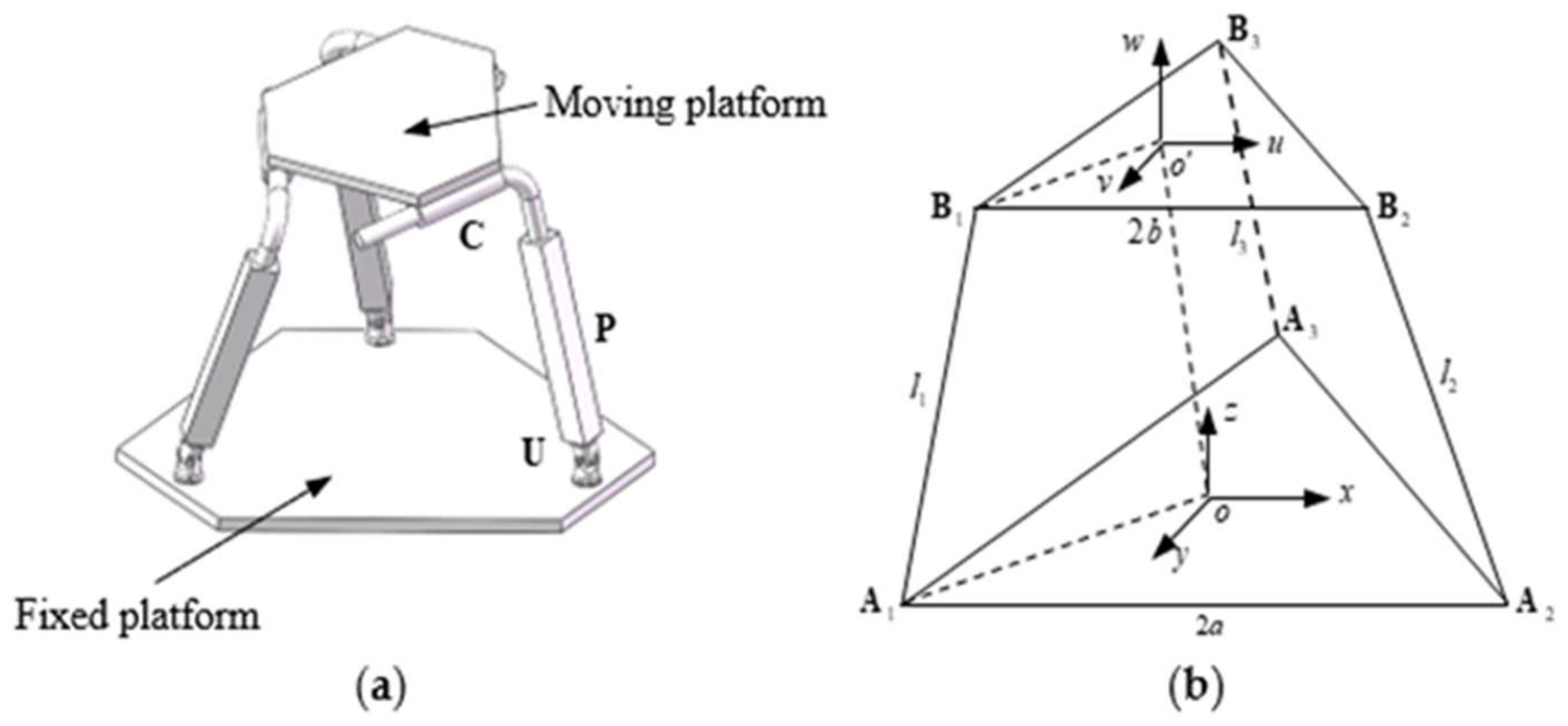
The 3-UPC type parallel prototype manipulator is composed of a moving platform, fixed platform and three symmetrical links [36]. Each link is composed by a universal joint (U) that is connected to the fixed platform, a cylindrical joint (C) that is connected to the moving platform, and an actuated prismatic joint (P) that is used to connect the universal joint with the cylindrical joint. Its structural configuration is shown in Figure 1.
The coordinate system is fixed to the base platform, and the coordinate system is fixed to the moving platform. The connection point of the limb (sub-chain) lying on the base platform is denoted by vector , , and the connection point of limb (sub-chain) lying on the moving platform is denoted by vector , . The limbs are of equal initial length, their value is constant and equal to , which means . The upper and base platforms are in the shape of an equilateral triangle, and the lengths of the upper and base platforms are and , respectively.
The kinematic properties of the 3-UPC type parallel manipulator have been analyzed by means of screw theory in [37]. The compliant mechanism obtained by the topology optimization method is characterized by a micro/nanoscale motion. If factors such as friction and joint clearance are not taken into account, theoretically the parallel prototype mechanism could achieve the same micro/nanoscale motion as the compliant mechanism. Under these circumstances, it is likely that the motion range of each motion branch in the parallel prototype will tend to be infinitesimal. Assuming that the three kinematic rotational parameters were , and that the initial topological convergence conditions were set as 1 × 10⁻⁶ rad, without loss of generality, the following approximation was adopted: and . As the product of two infinitesimal quantities is a high order infinitesimal, we can assume that . The above hypothesis applies equally to and .
According to the Euler method and assumptions, the rotational transformation matrix is given by
where and .
Assuming that the driving force is provided by peristaltic joint, and the value of actuated is , , the vector equations can be written as follows
Multiplying the rotational transformation matrix by the original coordinate frame of , the coordinate frame of is derived as
Substituting the original coordinate frames into Equation (3), the isomorphic mapping matrix can be written as follows
where is the Jacobian isomorphic mapping matrix used for the topology optimization process.
3. Topology Optimization Model of the Three-DOF Spatially Compliant Mechanism
3.1. Model of the Solid Isotropic Material with Penalization (SIMP)
Combining the finite element method with the optimization method, topology optimization is used to solve the material distribution problem in the area of a given design field according to the load or support constraints. The SIMP method is proposed on the basis of the relative density method, and the optimization process is determined by the unit selection and relative density with a penalty factor [25].
By introducing a penalty factor, a dominant nonlinear correspondence is established between the elastic modulus of the material and the relative density of the element, which makes the middle density value equal to 0 or 1. The relationship between the element density and element Young’s modulus can be written as follows
where is the elastic modulus of the solid material. is the penalty factor of the intermediate material density, and its values range can be defined as
where is the Poisson’s ratio.
The optimal model of the three-rotational DOF spatially compliant mechanism is described as follows
where is the density function, defined as , is the neighborhood of an element with volume , is a weight factor, is the number of elements, is element volume, is the convergence objective of the designed volume. The nodal force vector is the input force vectors, and is the output with displacement vector. By using Equation (4), the displacement with input and output is the solution of . is the whole stiffness of the compliant mechanism, and is the element of the displacement vector, is the element of the displacement vector. is the stiffness of the element and is the density of the element.
3.2. Sensitivity Analysis
Using the sensitivity values of the objective and constraint functions, the change of direction of the design variables during the topology optimization process can be determined.
Deriving the volume constraint in Equation (7) with respect to the design variable , yields to
where and .
A hexahedral element structure was adopted to mesh the partition grid, that is, .
The compliance sensitivity is satisfied by the following equation
where the nodal displacement vector is the solution of the equilibrium equation, , and its derivative with respect to is satisfied by
Which yields
The element stiffness matrices and are used to satisfy Equation (12)
then,
Equation (11) can be rewritten as
Since is element stiffness matrix, Equation (14) can be denoted as
where is the nodal displacement vector element, and is positive definite, then
The derivative of the objective function with the design variables is
Without the loss of generality, input load independence from design variables was assumed. Differentiating the design variables of Equation (7) with respect to the stiffness matrix, yields
Substituting into Equation (18) and using Equation (17), the sensitivity of the objective function can be given by
With the volume as the optimization constraint, the partial derivative of the volume with respect to the material density is given by the constraint function sensitivity:
3.3. Solution of the Topology Optimization Model
Based on the variation principle, the function equation that contains the compliance, objective, and constraint functions can be built using the Lagrange multiplier. The update iteration of the multi-input–output in the three-dimensional space is given by:
where is the iteration value of step, is the iteration value of step, m is the moving limit constant (m = 0.1~0.3) and is the damping factor ( = 0.4~0.5).
is expressed as follows:
is the Lagrange multiplier with the volume constraint of step iteration, updated adopting bi-directional convex linear programming method, and is the element volume of step iteration.
4. Topology Structure of the Three-DOF Spatially Compliant Mechanism
4.1. Design Domain and Iterative Algorithm
In this section, the design of three-dimensional space actuators is carried out, and in all cases boundary conditions forcing the treatment of the design object as a three-dimensional problem are adopted. Three directions of actuating displacement are used to design the three-DOF spatially compliant mechanism. The initial design domain is shown in Figure 2, where the dimensions are also indicated.
The domain is a cube of dimension 125 mm × 125 mm × 125 mm discretized with 2000 eight node elements. In order to reduce analysis computation time, the Hypermesh@ software (version 2017, Altair Engineering, Troy, MI, USA) was used to mesh the partition. In this case it is assumed that the three-DOF spatially compliant mechanism will consist of a material with a Young’s modulus 2.06 × 10⁻⁵ F/mm2 and Poisson’s ratio 0.3. Considering the literature [38] and the actuated configuration of a parallel prototype manipulator, the design three-DOF spatially compliant mechanism is set to three actuated loads of , and three constraint displacements are designed at the center point of the top domain. The volume restriction is 20 percent of the design domain. For the elastic workpiece, a value of 2 × 10⁶ mN/m is assigned to the spring constant.
The iterative algorithm of topology optimization for the three-DOF spatially compliant mechanism is given as follows.
Step 1: The hexahedral mesh method is used to divide the design region of Figure 2 into grids, and the size of the grid is determined.
Step 2: According to the spatially geometric constraint of a parallel prototype manipulator of the 3-UPC type, the boundary constraints and load conditions are defined, and combined with the SIMP topology optimization method, proposed in Equation (7).
Step 3: Initial values are assigned to the design variables.
Step 4: Equation (21) is differentiated with the flexibility function.
Step 5: The sensitivity of the constraint function is calculated using Equation (7), and the sensitivities of the material density and design variables are derived by Equation (18) and (20), respectively.
Step 6: The optimization criteria denoted by Equation (21) are calculated, and the design variables are updated as in Equation (22). The mesh elements of the design domain will be removed if they satisfy Equation (16).
Step 7: The optimization process will terminate when the remaining elements satisfy the volume constraint in Equation (8) and (17). Otherwise, the process will return to Step 4.
4.2. The Topology Optimization Structure of the Three-DOF Spatially Compliant Mechanism
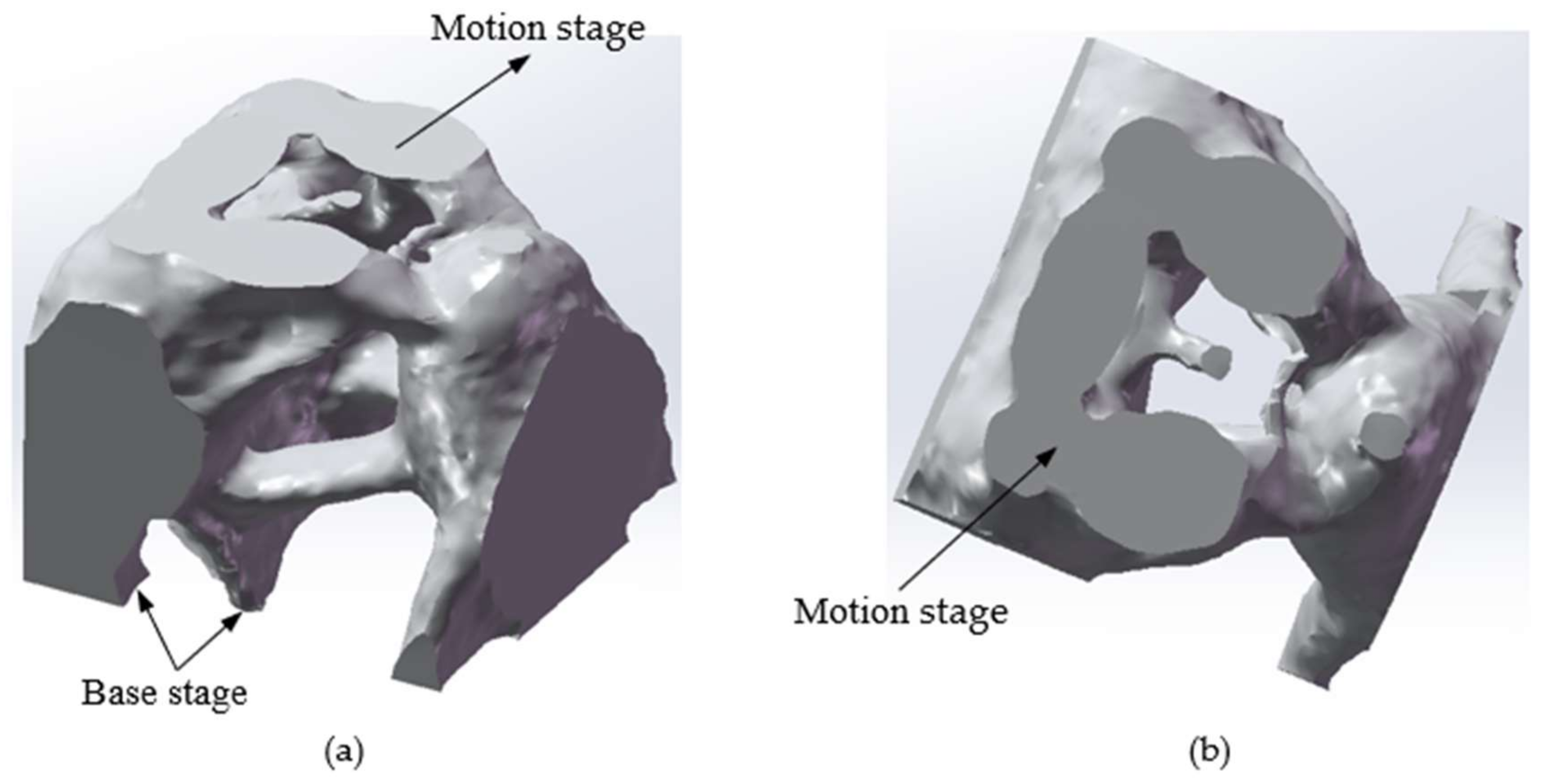
The topology optimization structure of the three-DOF spatially compliant mechanism with an isomorphic mapping matrix can be obtained as shown in Figure 3. The topology optimization iteration procedure of the three-DOF spatially compliant mechanism is shown in Figure 4 and converges after four iterative steps.
5. Numerical Implementation
5.1. Analysis of Differential Kinematic Characteristics
The differential kinematic approximation method is used to derive the isomorphic mapping matrix as reported in Section 2. Furthermore, this isomorphic mapping matrix is applied to the topology optimization process as a constraint condition. The SimMechanical@ software (version 2013a, MathWorks, Inc., Natick, MA, USA) is adopted to build a model of the 3-UPC type parallel prototype manipulator under the initial structural conditions that are shown as Table 1.
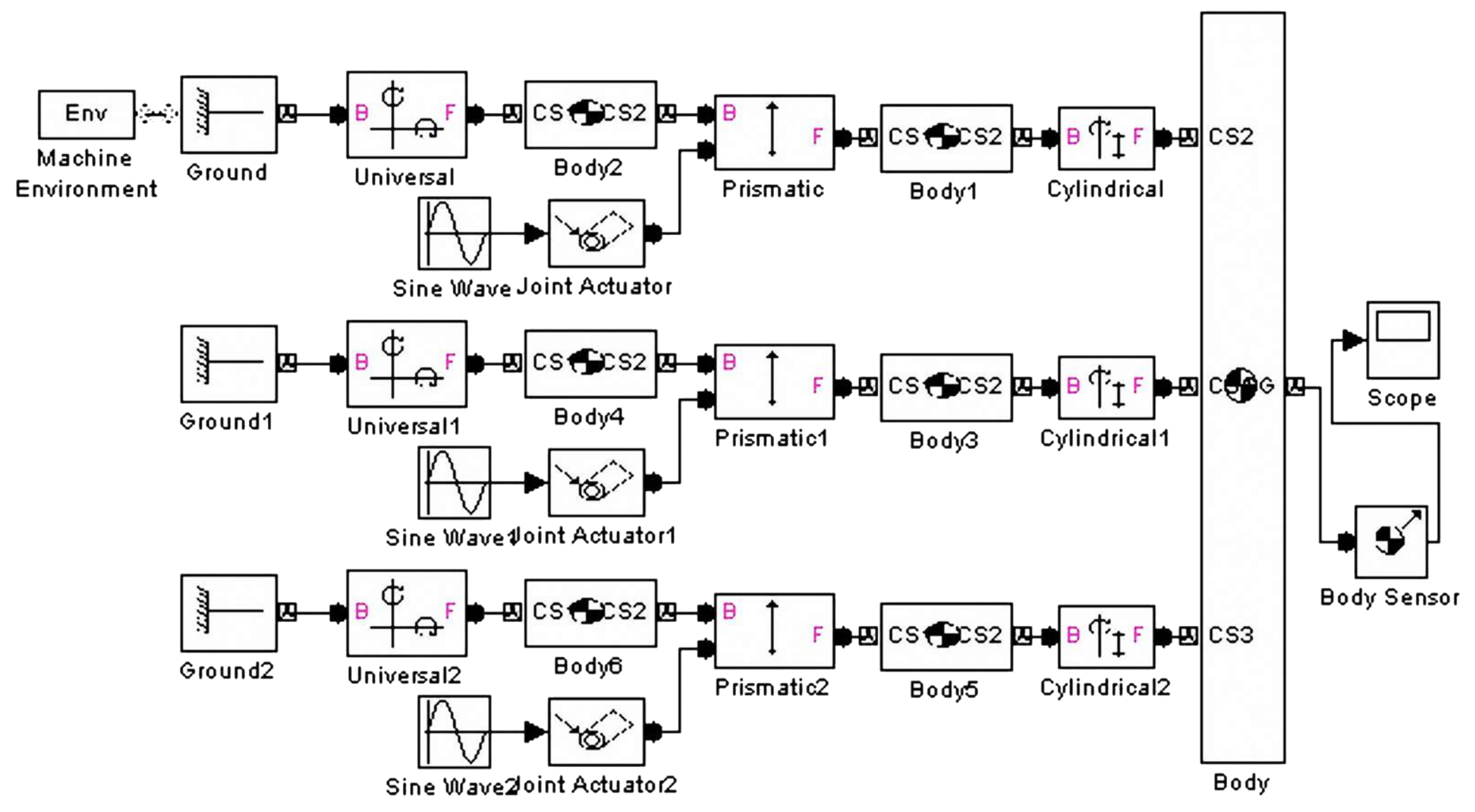
The structure of the 3-UPC type parallel prototype manipulator is shown in Figure 5.
Substituting the structural initial parameters into Equation (4), the isomorphic mapping matrix can be given by
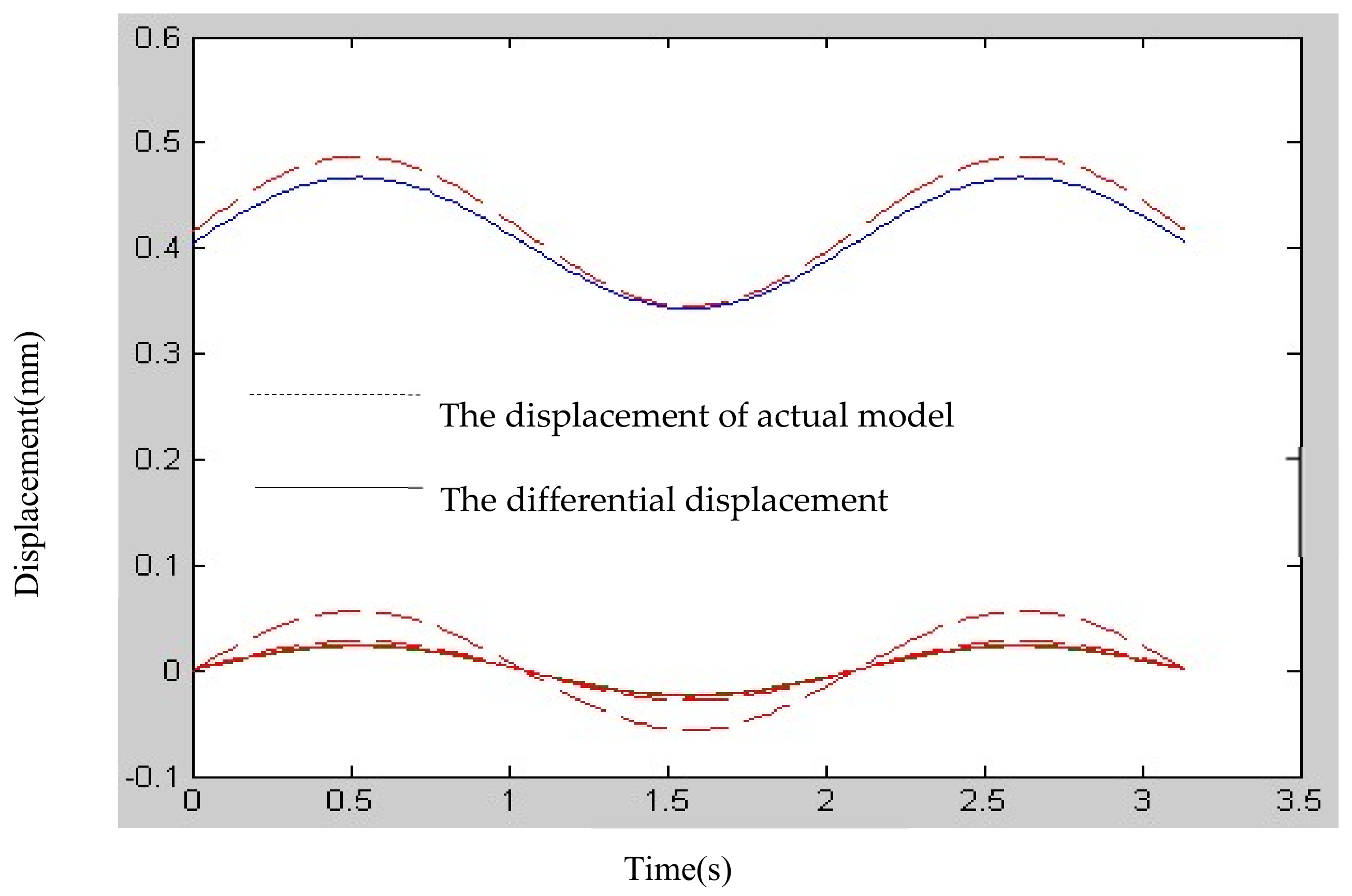
Figure 6 shows that the isomorphism mapping matrix obtained using differential kinematic approximation methods maintains the isomorphic kinematic characteristics of the 3-UPC type parallel prototype manipulator, and its kinematic errors corresponding to small signal inputs are 0.34%, 0.56% and 1.56%, respectively.
5.2. Differential Kinematic Characteristics of the Topology Optimization Structure
5.3. Experimental Study
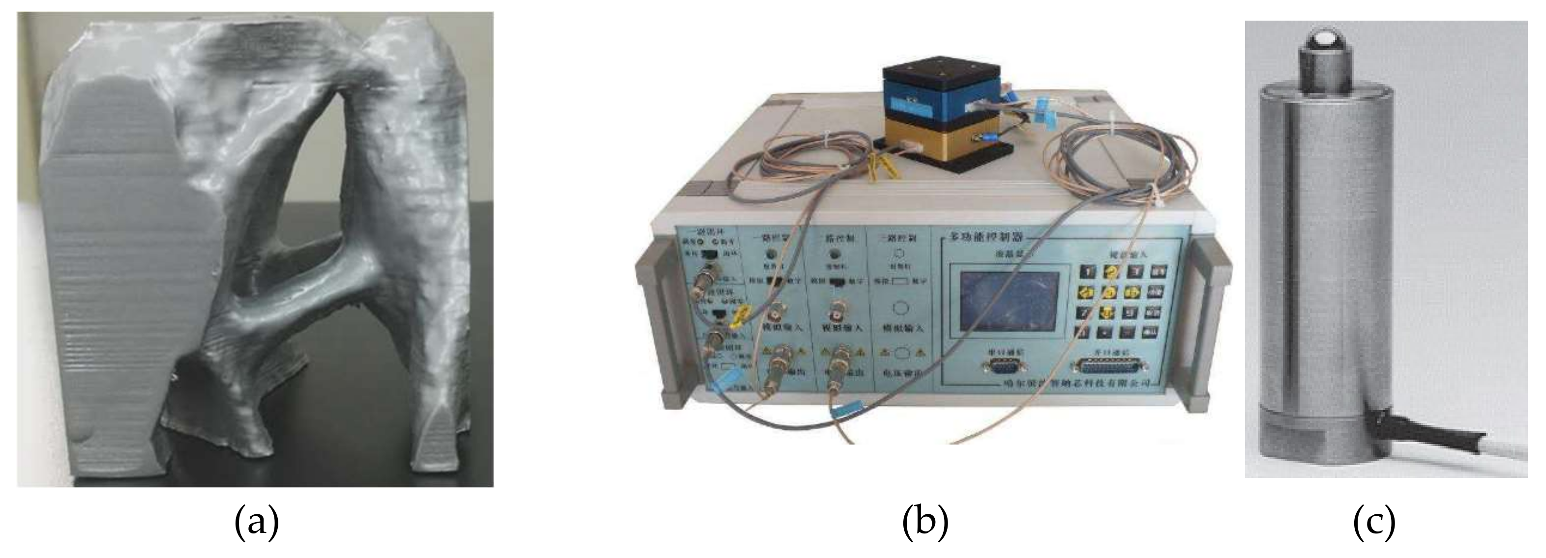
Before the optimization, a background hexahedron mesh was set up for the reference domain. In each iteration step of the optimization process, the modification of the fixed background mesh was performed to obtain a mesh that is conformal to the geometry of the compliant mechanism. On the other hand, in order to place the piezoelectric (PZT) actuator, three non-design areas were set according to the driver configuration characteristics of the parallel prototype manipulator. The output displacements corresponding to the center of the top platform were measured by Renishaw laser interferometer, and the experiments were conducted under a closed-loop control strategy by using a proportional-integral-derivative (PID) controller. The parameters of three PZT actuators are given in Table 3.
The topological structure, controller and actuator are shown in Figure 9. A formula for the calculation of voltage and output of the PZT actuators is used:
where is the output of PZT actuators, is electrostatic capacity, is the constant parameter, is the width of PZT actuator, is the installation channel, is the thickness of PZT, and is the applied voltage.
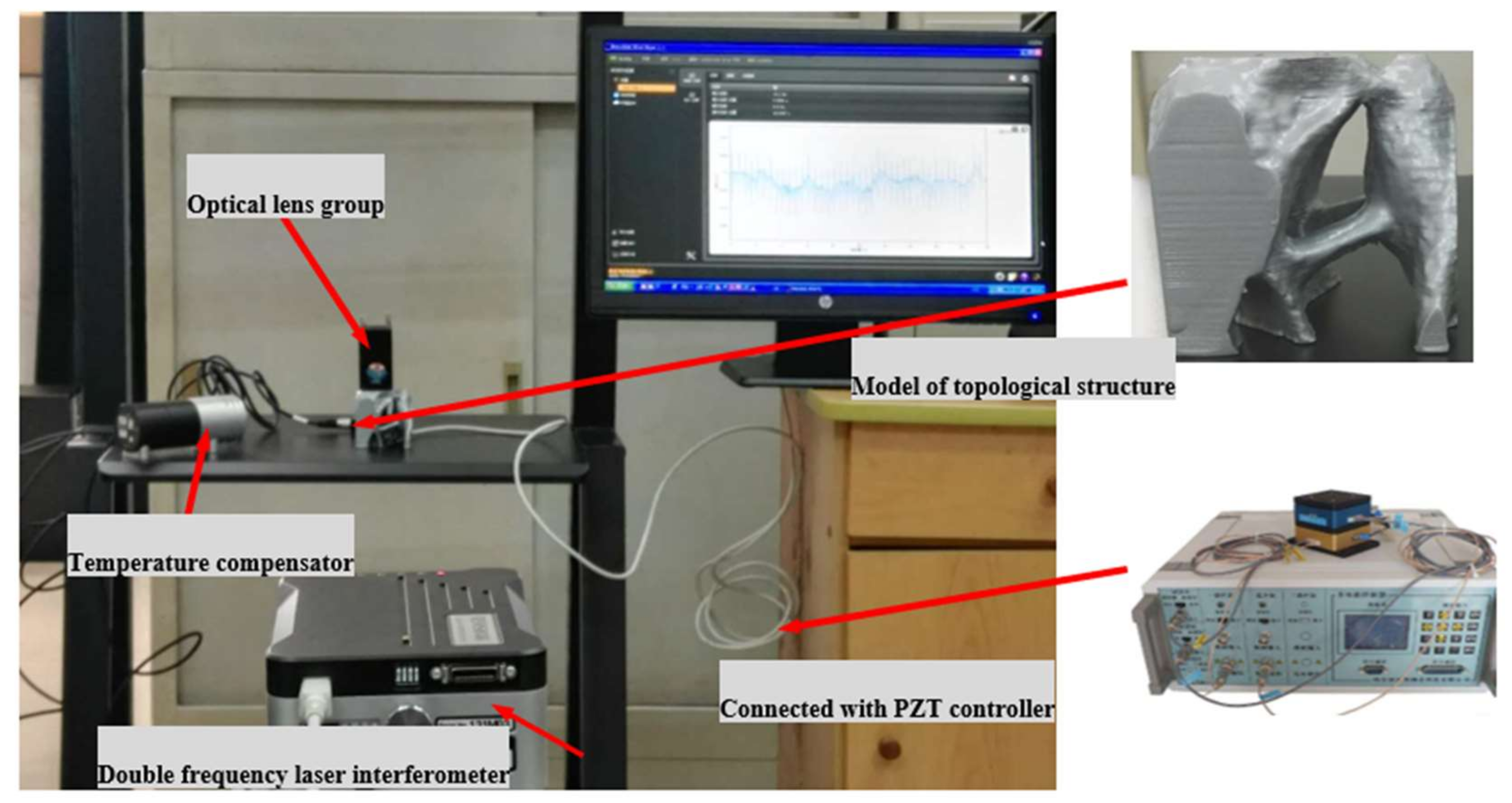
The experimental device is shown in Figure 10. The nominal stroke is the displacement stroke corresponding to the driving voltage of 0–150 V; for high reliability long term use, the recommended driving voltage is 0–120 V, and the maximum output up to 25,000N.
5.4. Experimental Results and Analysis
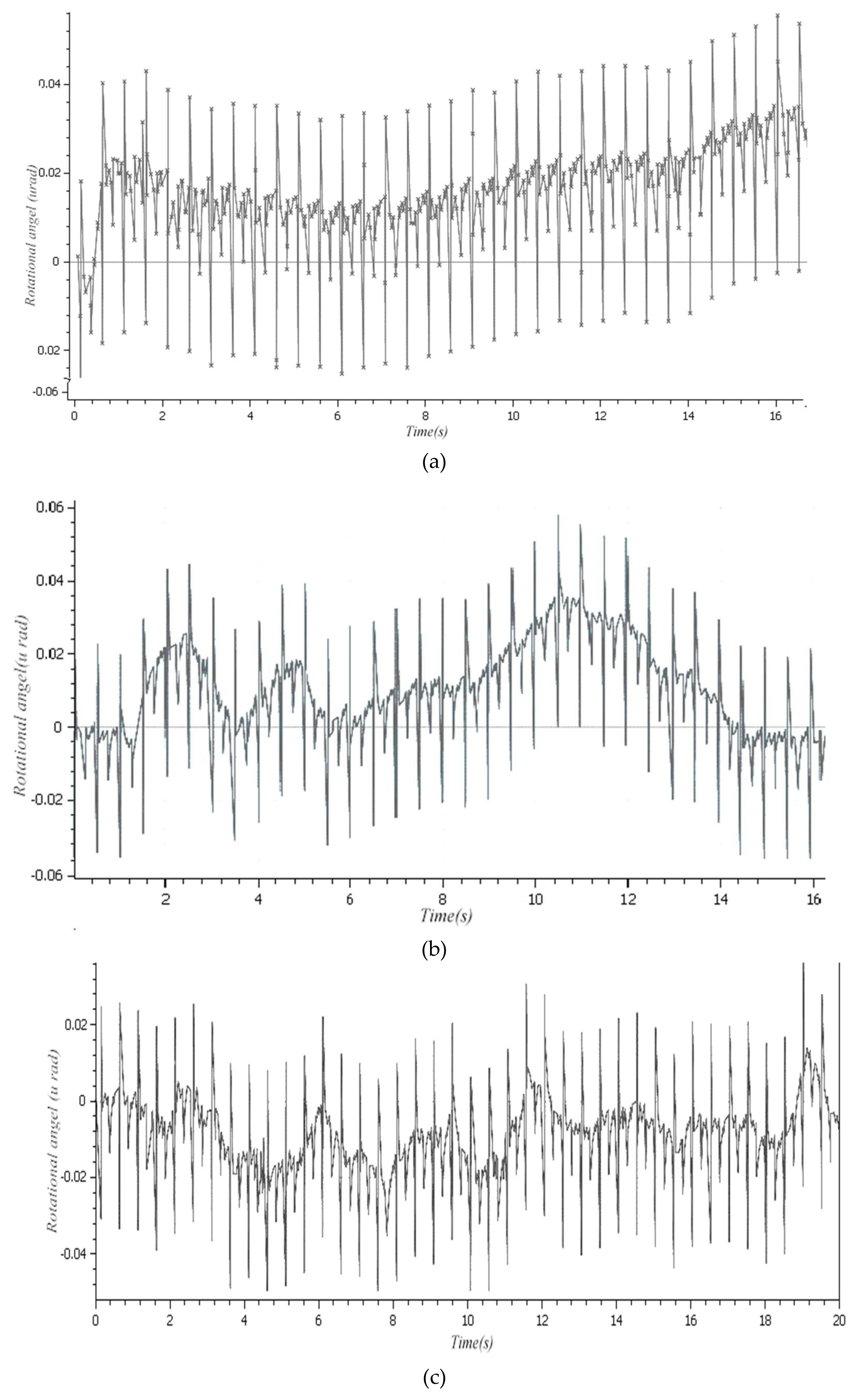
A double frequency laser interferometer was used to obtain the precise position of three rotational directions , the displacement step was 33.5 nm, and the initial voltage of the PZT actuators was 20 V. The measurement results are shown in Figure 11a–c, respectively.
The comparison of the kinematic results between the simulation and experiment is given in Table 4.
It can be seen that the experimental results are not compatible with the theoretical simulation results due to the three actuators mounted during the 3D printing process, consistency of surface shape, and so on. Therefore, in the processing of the spatially compliant mechanism, it is necessary to take into account the shape error of its topological configuration.
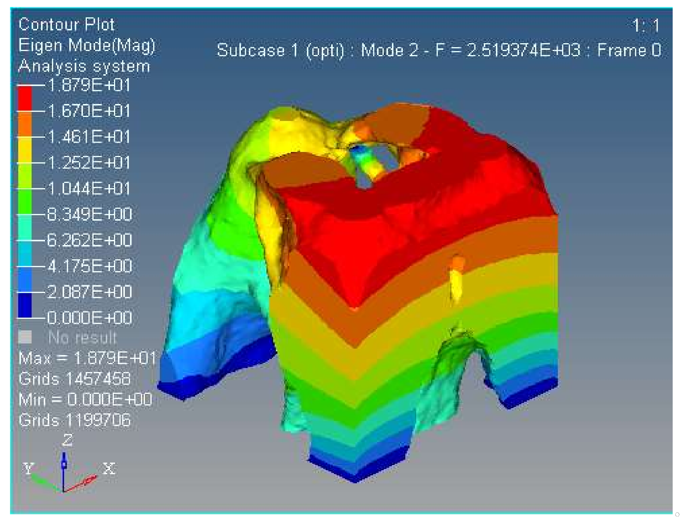
5.5. Modal Analysis of the First Three Orders
Modal analysis is inherent to the vibration characteristics of mechanical structures, and it is important in the micro/nano manufacturing field. The Optistruct software was used to analyze the first and second modal of the spatially compliant mechanism proposed in this paper, and modal analysis is proposed for the same input load conditions and boundary constraint conditions. The first and second order modal analyses are shown in Figure 12 and Figure 13, respectively.
The results show that the natural frequency is higher than the same compliant mechanism with the hinge replacement method proposed in the literature [17].
6. Conclusions
In this paper, a topology optimization approach was proposed for the design of three rotational degree-of-freedom (DOF) spatially compliant mechanisms. In this method, the isomorphic Jacobian matrix of the 3-UPC type parallel prototype manipulator was calculated, and then the orthogonal triangular decomposition and differential kinematic method were applied to uncouple the Jacobian matrix in order to construct a constraint field of topology optimization. Firstly, in terms of the 3-UPC type parallel prototype manipulator, the Jacobian matrix was derived to map the inputs and outputs to be used during the topology optimization process. Secondly, orthogonal triangular decomposition with the differential kinematic method was used to reconstruct the uncoupled mapping matrix for the topology optimization process. Finally, the SIMP method was applied to construct the topological model in combination with the isomorphic mapping matrix. A typical three rotational DOF spatially compliant mechanism was used as a numerical example to demonstrate the effectiveness of the proposed method.
- (1)
- In order to build accurate modeling after the structural topology optimization, the SIMP topology optimization method combined with the isomorphic mapping matrix of 3-UPC type parallel prototype manipulator was used for the structural synthesis for the spatially compliant mechanism with three rotational DOFs.
- (2)
- The optimized three-DOF spatially compliant mechanism with the isomorphic mapping matrix was imported to Hyperworks for finite element static analysis. The maximum and minimum rotational angles of 0.47 × 10⁻⁴ rad and −0.21 × 10⁻⁴ rad in x direction, 0.51 × 10⁻⁴ rad and −0.46 × 10⁻⁴ rad in y direction, and 0.12 × 10⁻⁴ rad and −0.48 × 10⁻⁵ rad in z direction were obtained by simulation, while the corresponding experimental rotational angles of the maximum and minimum were 0.36 × 10⁻⁴ rad and −0.18 × 10⁻⁴ rad in x direction, 0.39 × 10⁻⁴ rad and −0.12 × 10⁻⁴ rad in y direction, and 0.18 × 10⁻⁴ rad and −0.32 × 10⁻⁴ rad in z direction, respectively.
- (3)
- The comparative simulation studies, the stress distribution and the first/second order modal of the proposed spatially compliant mechanism, show that the proposed method can ensure the integral isomorphism characteristics between the proposed spatially compliant mechanism and the conventional parallel prototype manipulator with uniform stiffness and vibration suppression.
- (4)
- The compliant mechanism obtained through the topology optimization had a very irregular shape, which is related to the configuration of the topological optimization conditions. By using a topological optimization method combining a Jacobian matrix with the SIMP method of isomorphism mapping, regardless of the initial optimization conditions, the resulting topologies all had the same differential motion characteristics as the parallel prototype mechanism, i.e., isomorphism. The piezoelectric actuator is in an enclosed space and its spatial configuration is determined based on the parallel prototype mechanism actuator configuration. The approach adopted consisted of interrupting the printing process during 3D printing and resuming it once the piezoelectric actuator is implanted. Therefore, there is no better way to implement the driver than the 3D printing technology.
Acknowledgments
This work was supported by the National Natural Science Foundation of China under Grant No. 51165009/50965007, Science and Technology Project of Jiangxi Province (China) under Grant No. 20142BAB206019, Provincial Key Platform and Major Scientific Research Project of Higher Education of Guangdong Province of China under Grant No. 2017KZDXM060. The authors would like to thank Huacai Intelligent Equipment Technology Co., Ltd., in Guangzhou for supporting them with the experimental setup. The authors would also like to thank the reviewers and the editor for their efforts in improving the paper.
Author Contributions
Dachang Zhu designed the whole project framework; Fupei Wu and Dachang Zhu conceived and designed the experimental process; and Wanghu Zhan performed the experiments; Dachang Zhu and Alessandro Simeone analyzed the data; Dachang Zhu and Fupei Wu wrote the paper and Alessandro Simeone revised the manuscript of this paper.
Conflicts of Interest
The authors declare no conflict of interest. The founding sponsors had no role in the design of the study; in the collection, analyses, or interpretation of data; in the writing of the manuscript, and in the decision to publish the results.
References
- Howell, L.L. Compliant Mechanisms; Wiley: New York, NY, USA, 2001. [Google Scholar]
- Xu, Q. New flexure parallel-kinematic micro-positioning system with large workspace. IEEE Trans. Robot. 2012, 28, 478–491. [Google Scholar] [CrossRef]
- Valentini, P.P.; Pennestri, E. Second-order approximation pseudo-rigid model of leaf flexure hinge. Mech. Mach. Theory 2017, 116, 352–359. [Google Scholar] [CrossRef]
- Pucheta, M.A.; Cardona, A. Design of bi stable compliant mechanisms using precision-position and rigid-body replacement methods. Mech. Mach. Theory 2010, 45, 304–326. [Google Scholar] [CrossRef]
- Naves, M.; Brouwer, D.M.; Aarts, R.G. Building block-based spatial topology synthesis method for large-stroke flexure hinges. ASME Trans. J. Mech. Robot. 2017, 9, 041006. [Google Scholar] [CrossRef]
- Liu, M.; Zhang, X.; Fatikow, S. Design and analysis of a multi-notched flexure hinge for compliant mechanisms. Precis. Eng. 2017, 48, 292–304. [Google Scholar] [CrossRef]
- Rad, F.P.; Berselli, G.; Vertechy, R.; Parenti-Castelli, V. Design and stiffness analysis of a compliant spherical chain with three degrees of freedom. Precis. Eng. 2017, 47, 1–9. [Google Scholar]
- Zhao, S.S.; Bi, S.S.; Zong, G.H.; Yu, J. New large-deflection flexure pivot based on curved flexure element. Chin. J. Mech. Eng. 2009, 45, 8–12. [Google Scholar] [CrossRef]
- Xu, Q. Design, testing and precision control of a novel long-stroke flexure micropositioning system. Mech. Mach. Theory 2013, 70, 209–224. [Google Scholar] [CrossRef]
- Trease, B.P.; Moon, Y.M.; Kota, S. Design of large displacement compliant joints. J. Mech. Des. 2004, 127, 788–798. [Google Scholar] [CrossRef]
- Choi, Y.J.; Sreenivasan, S.V.; Choi, B.J. Kinematic design of large displacement precision XY positioning stage by using cross strip flexure joints and over-constrained mechanism. Mech. Mach. Theory 2008, 43, 724–737. [Google Scholar] [CrossRef]
- Tan, K.; Zong, G.H.; Bi, S.S.; Yu, Z. Multi-leaf configuration of expanded-motion-range flexure hinges. Dual Use Technol. Prod. 2007, 3, 38–39. [Google Scholar]
- Hao, G.; Kong, X. A normalization-based approach to the mobility analysis of spatial compliant multi-beam modules. Mech. Mach. Theory 2013, 59, 1–19. [Google Scholar] [CrossRef]
- Howell, L.L.; Midah, A. A method for the design of compliant mechanisms with small-length flexural pivots. J. Eng. Des. 1994, 116, 280–289. [Google Scholar] [CrossRef]
- Howell, L.L.; Midah, A. A loop-closure theory for the analysis and synthesis of compliant mechanisms. J. Mech. Des. 1996, 118, 121–125. [Google Scholar] [CrossRef]
- Lum, G.Z.; Teo, T.J.; Yang, G.; Yeo, S.H.; Sitti, M. Integrating mechanism synthesis and topological optimization technique for stiffness-oriented design of a three degrees-of-freedom flexure-based parallel mechanism. Precis. Eng. 2015, 39, 125–133. [Google Scholar] [CrossRef]
- Verotti, M.; Dochshanov, A.; Belfiore, N.P. A comprehensive survey on modern microgrippers design: Mechanical structure. J. Mech. Des. 2017, 139, 060801. [Google Scholar] [CrossRef]
- Hudgens, J.; Tesar, D. A fully-parallel six degree-of-freedom micromanipulator: Kinematic analysis and dynamic model. In Proceedings of the 20th Biennial ASME Mechanisms Conference, Kissimmee, FL, USA, 25–28 September 1988; pp. 29–37. [Google Scholar]
- Mclnroy, J.E.; Hamann, J.C. Design and control of flexure jointed hexapods. IEEE Trans. Robot. Autom. 2000, 16, 372–381. [Google Scholar] [CrossRef]
- Yi, B.J.; Chung, G.B.; Na, H.Y.; Kim, W.K.; Suh, I.H. Design and experiment of 3-dof parallel micromechanism utilizing flexure hinges. IEEE Trans. Robot. Autom. 2003, 19, 604–612. [Google Scholar]
- Hao, G.; Li, H. Conceptual design of multi-DOF compliant parallel manipulators composed of wire-beam based compliant mechanisms. Proc. Inst. Mech. Eng. Part C 2015, 229, 538–555. [Google Scholar] [CrossRef]
- Sigmund, O. On the design of compliant mechanisms using topology optimization. Mech. Struct. Mach. 1997, 25, 493–524. [Google Scholar] [CrossRef]
- Sigmund, O. Design of multiphysics actuators using topology optimization-Part I: One-material structures. Comput. Methods Appl. Mech. Eng. 2001, 190, 6577–6604. [Google Scholar] [CrossRef]
- Sigmund, O. Design of multiphysics actuators using topology optimization-Part II: Two-material structures. Comput. Methods Appl. Mech. Eng. 2001, 190, 6605–6627. [Google Scholar] [CrossRef]
- Nishiwaki, S.; Frecker, M.I.; Min, S.; Kikuchi, N. Topology optimization of compliant mechanisms using the homogenization method. Int. J. Num. Methods Eng. 1998, 42, 535–559. [Google Scholar] [CrossRef]
- Saxena, A.; Ananthasuresh, G.K. On an optimal property of compliant topologies. Struct. Multidiscip. Optim. 2000, 19, 36–49. [Google Scholar] [CrossRef]
- Wang, M.Y.; Steven, G.P. A simple evolution procedure for structural optimization. Comput. Struct. 1993, 49, 885–896. [Google Scholar]
- Saxena, A. Topology design of a large displacement compliant mechanisms with multiple materials and multiple output ports. Struct. Multidiscip. Optim. 2005, 30, 477–490. [Google Scholar] [CrossRef]
- Lu, K.; Kota, S. Topology and dimensional synthesis of compliant mechanisms using discrete optimization. J. Mech. Des. 2006, 128, 1080–1091. [Google Scholar] [CrossRef]
- Ansola, R.; Veguera, E.; Maturana, A.; Canales, J. 3D compliant mechanisms synthesis by a finite element addition procedure. Finite Elem. Anal. Des. 2010, 46, 760–769. [Google Scholar] [CrossRef]
- Ni, Z.; Zhang, D.; Wu, Y.; Tian, Y.; Hu, M. Analysis of parasitic motion in parallelogram compliant mechanism. Precis. Eng. 2010, 34, 133–138. [Google Scholar] [CrossRef]
- Verotti, M. Effect of initial curvature in uniform flexures on position accuracy. Mech. Mach. Theory 2018, 119, 106–118. [Google Scholar] [CrossRef]
- Pei, X.; Yu, J.; Zong, G.; Bi, S.; Yu, Z. Analysis of rotational precision for an isosceles-trapezoidal flexural pivot. J. Mech. Des. 2008, 130, 680–682. [Google Scholar]
- Jin, M.; Zhang, X. A new topology optimization method for planar compliant parallel mechanisms. Mech. Mach. Theory 2016, 95, 42–58. [Google Scholar] [CrossRef]
- Jin, M.; Zhang, X.; Zhu, B. A numerical method for static analysis of pseudo-rigid-body model of compliant mechanisms. Proc. Inst. Mech. Eng. C 2014, 228, 3170–3177. [Google Scholar] [CrossRef]
- Kong, X.; Gosselin, C. Type Synthesis of Parallel Mechanisms; Springer: Berlin/Heidelberg, Germany, 2007. [Google Scholar]
- Fang, Y.; Tsai, L.W. Structure synthesis of a class of 3-DOF rotational parallel manipulators. IEEE Trans. Robot. Autom. 2004, 20, 117–121. [Google Scholar] [CrossRef]
- Hao, G.; Kong, X. A structure design method for compliant parallel manipulators with actuation isolation. Mech. Sci. 2016, 7, 247–253. [Google Scholar] [CrossRef]
Figure 1.
3-UPC type parallel prototype manipulator (a) structure configuration model, (b) parameters with coordinate frame.
Figure 1.
3-UPC type parallel prototype manipulator (a) structure configuration model, (b) parameters with coordinate frame.

Figure 2.
Initial design domain of the three-DOF spatially compliant mechanism.
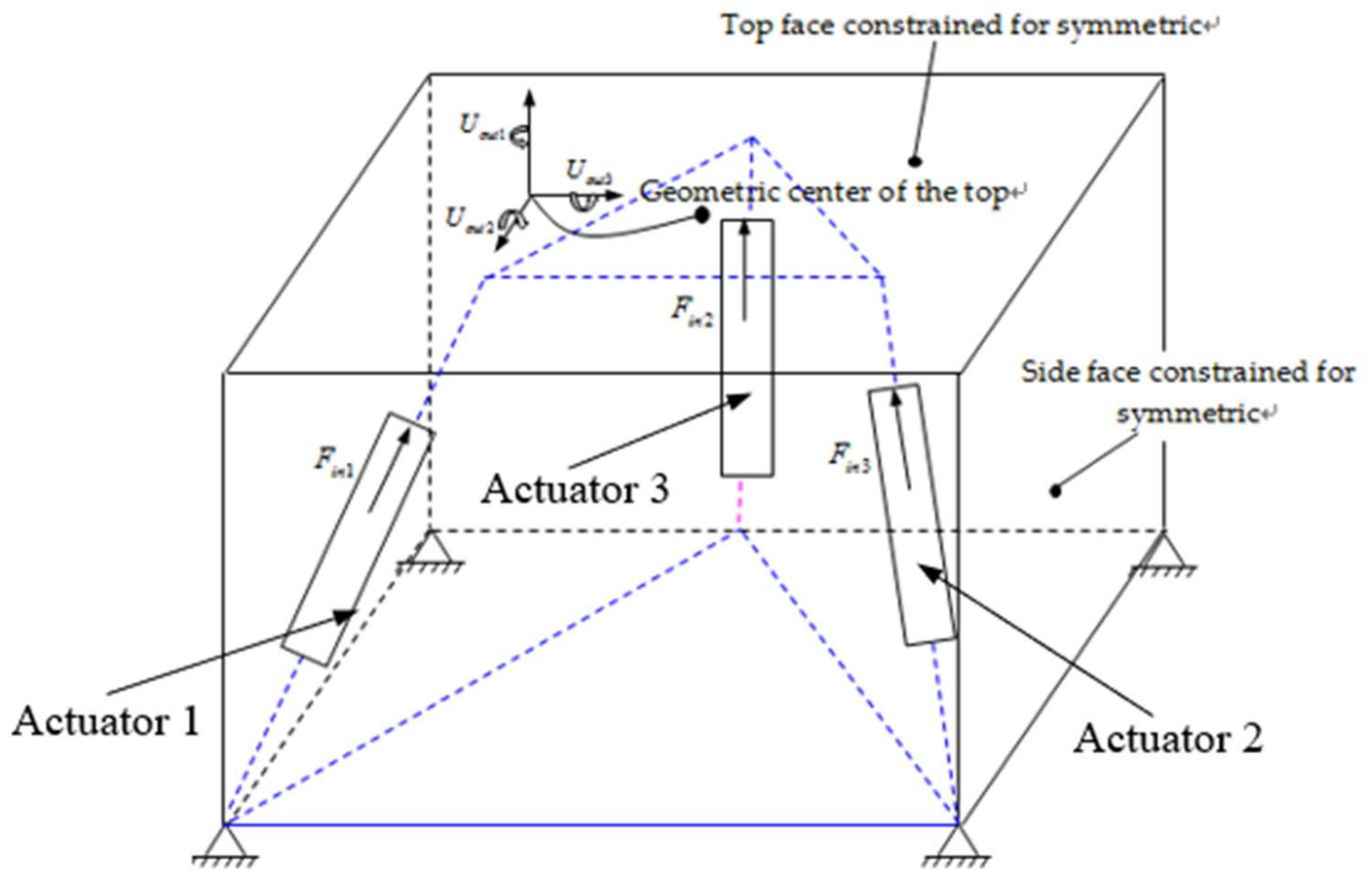
Figure 3.
Topology optimization structure of the three-DOF spatially compliant mechanism, (a) Structure of the three-DOF spatially compliant mechanism; (b) Top view of this structure.
Figure 3.
Topology optimization structure of the three-DOF spatially compliant mechanism, (a) Structure of the three-DOF spatially compliant mechanism; (b) Top view of this structure.

Figure 4.
Topology optimization iteration procedure of the three-DOF spatially compliant mechanism.
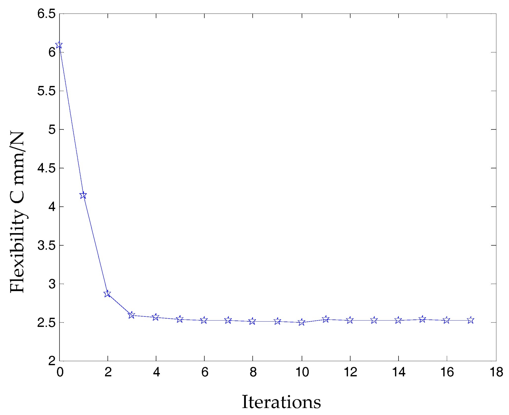
Figure 5.
Structure of the 3-UPC type parallel prototype manipulator using SimMechanical@ software.

Figure 6.
Forward kinematic comparison between differential kinematic approximation method and actual model of the 3-UPC type parallel prototype manipulator.
Figure 6.
Forward kinematic comparison between differential kinematic approximation method and actual model of the 3-UPC type parallel prototype manipulator.

Figure 7.
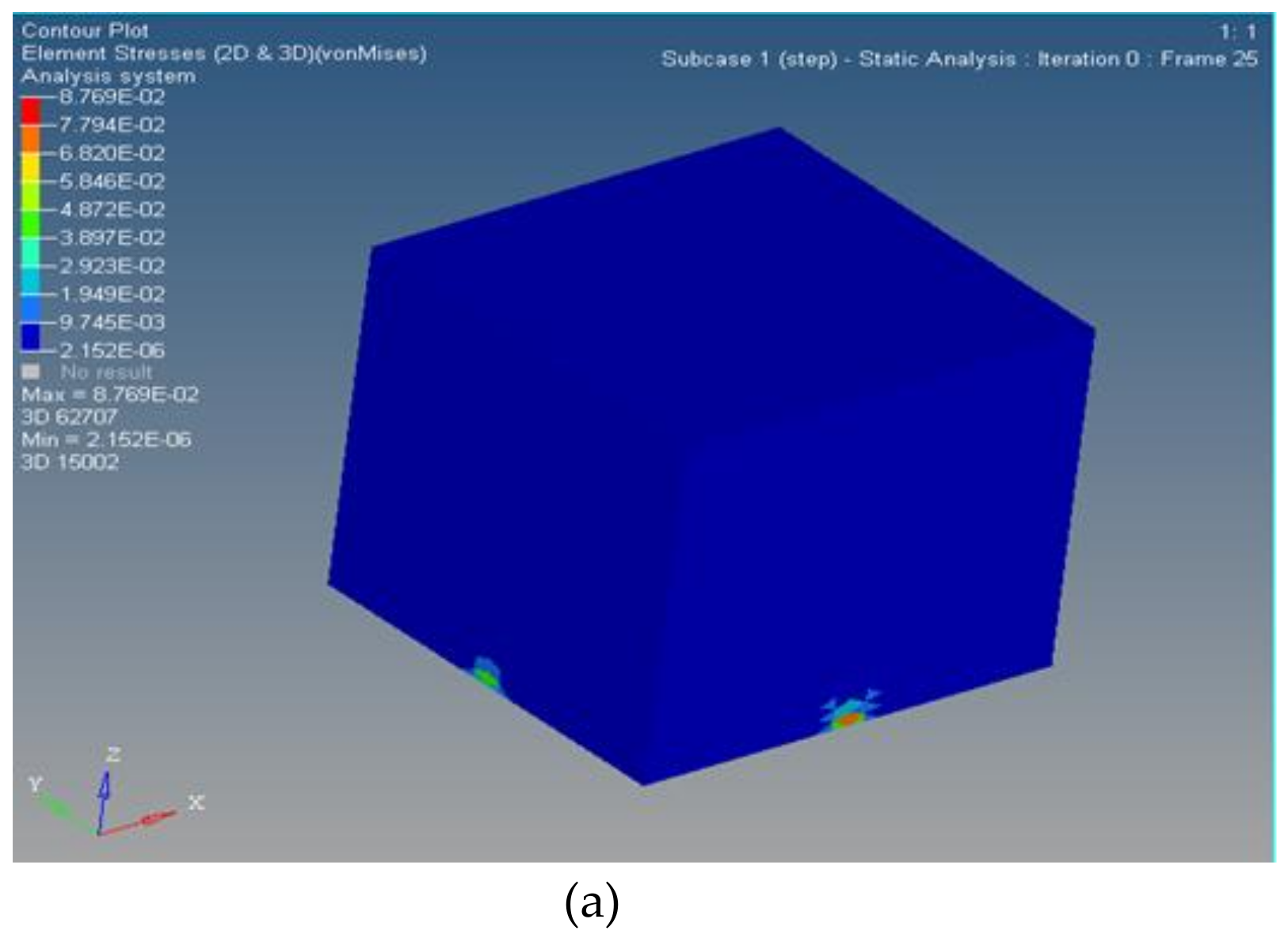
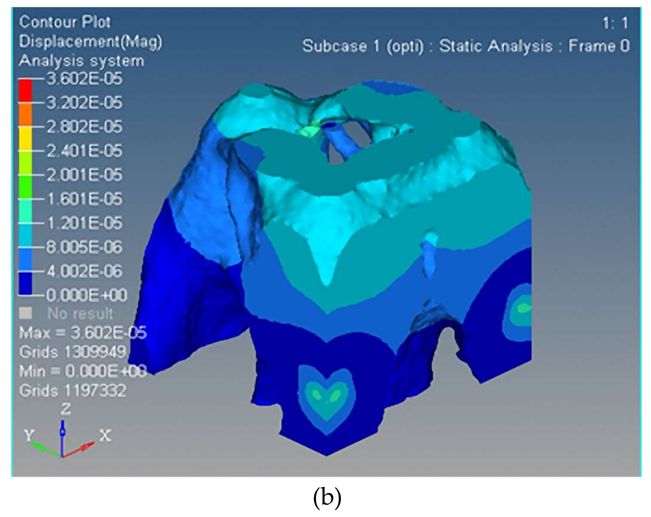
Stress distribution comparison: (a) before optimization; (b) after optimization.


Figure 8.
The three nano-scale-rotational displacements of the spatially compliant mechanism; (a) Along the -axis the maximum displacement is 7.774 × 10⁻⁷ rad and the minimum displacement is −6.299 × 10⁻⁷ rad; (b) Along the -axis the maximum displacement is 3.541 × 10⁻⁶ rad and the minimum displacement is −2.299 × 10⁻⁷ rad; (c) Along the -axis the maximum displacement is 4.344 × 10⁻⁶ rad and the minimum displacement is 0 rad.
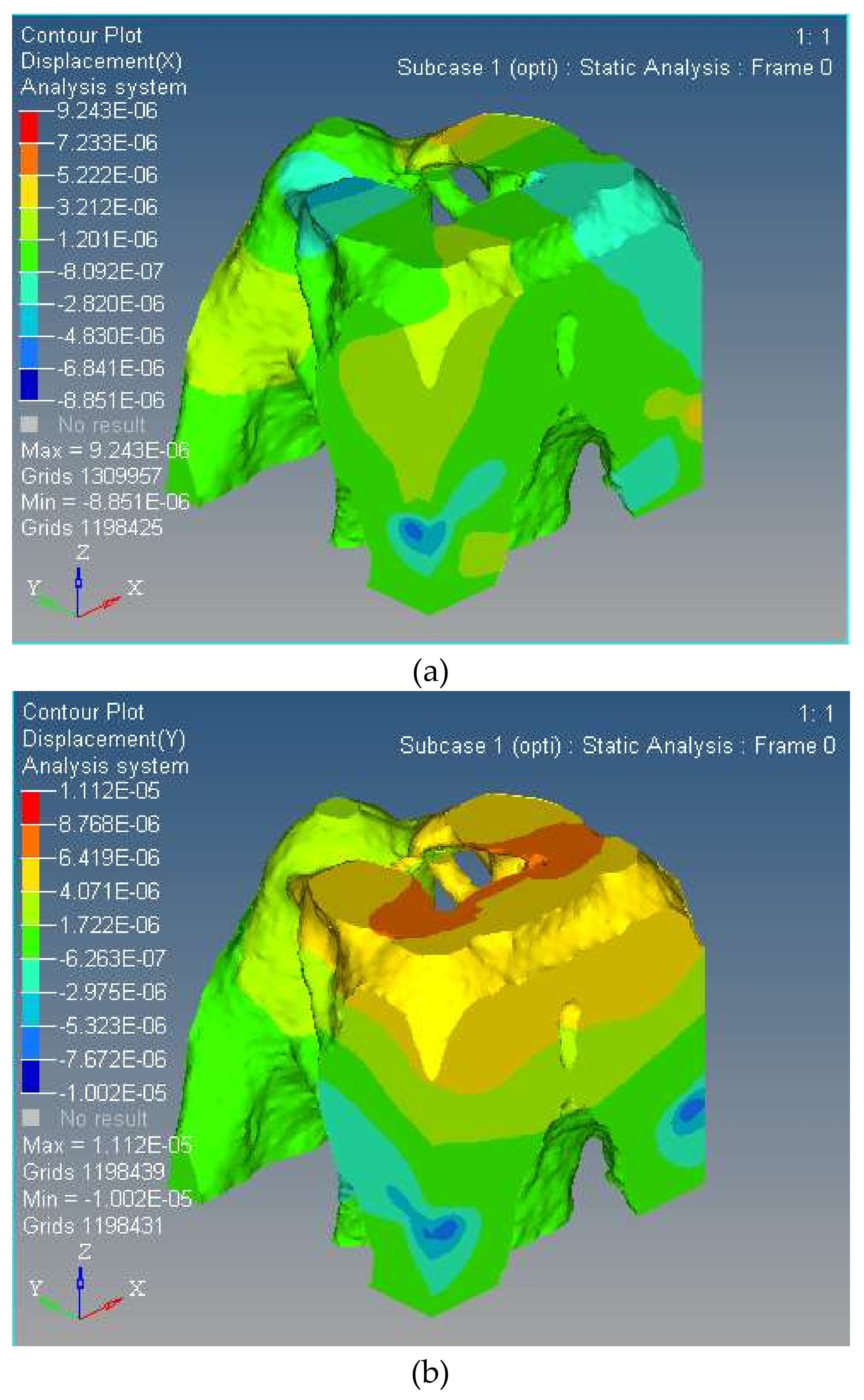
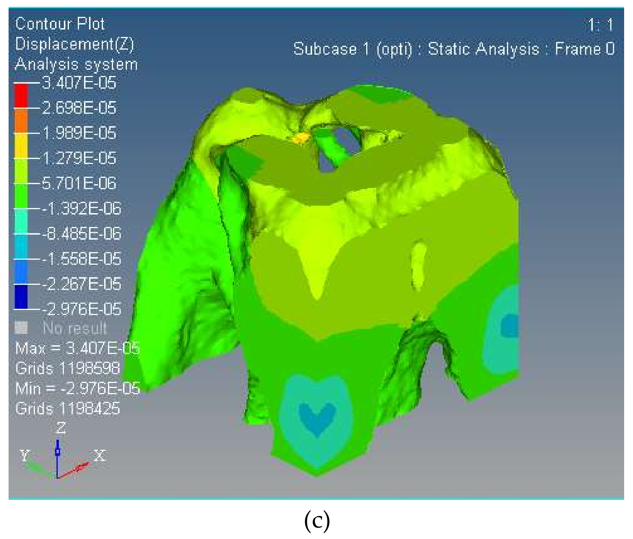
Figure 9.
Topological structure, controller and actuator. (a) The physical model of the topological structure, (b) Controller, (c) PZT actuator.
Figure 9.
Topological structure, controller and actuator. (a) The physical model of the topological structure, (b) Controller, (c) PZT actuator.

Figure 10.
Experimental device.

Figure 11.
Displacement of three rotational directions along axes; (a) Around -axis, (b) Around -axis, (c) Around -axis.
Figure 11.
Displacement of three rotational directions along axes; (a) Around -axis, (b) Around -axis, (c) Around -axis.

Figure 12.
First order modal of the proposed spatially compliant mechanism with three-rotational-DOFs.
Figure 12.
First order modal of the proposed spatially compliant mechanism with three-rotational-DOFs.
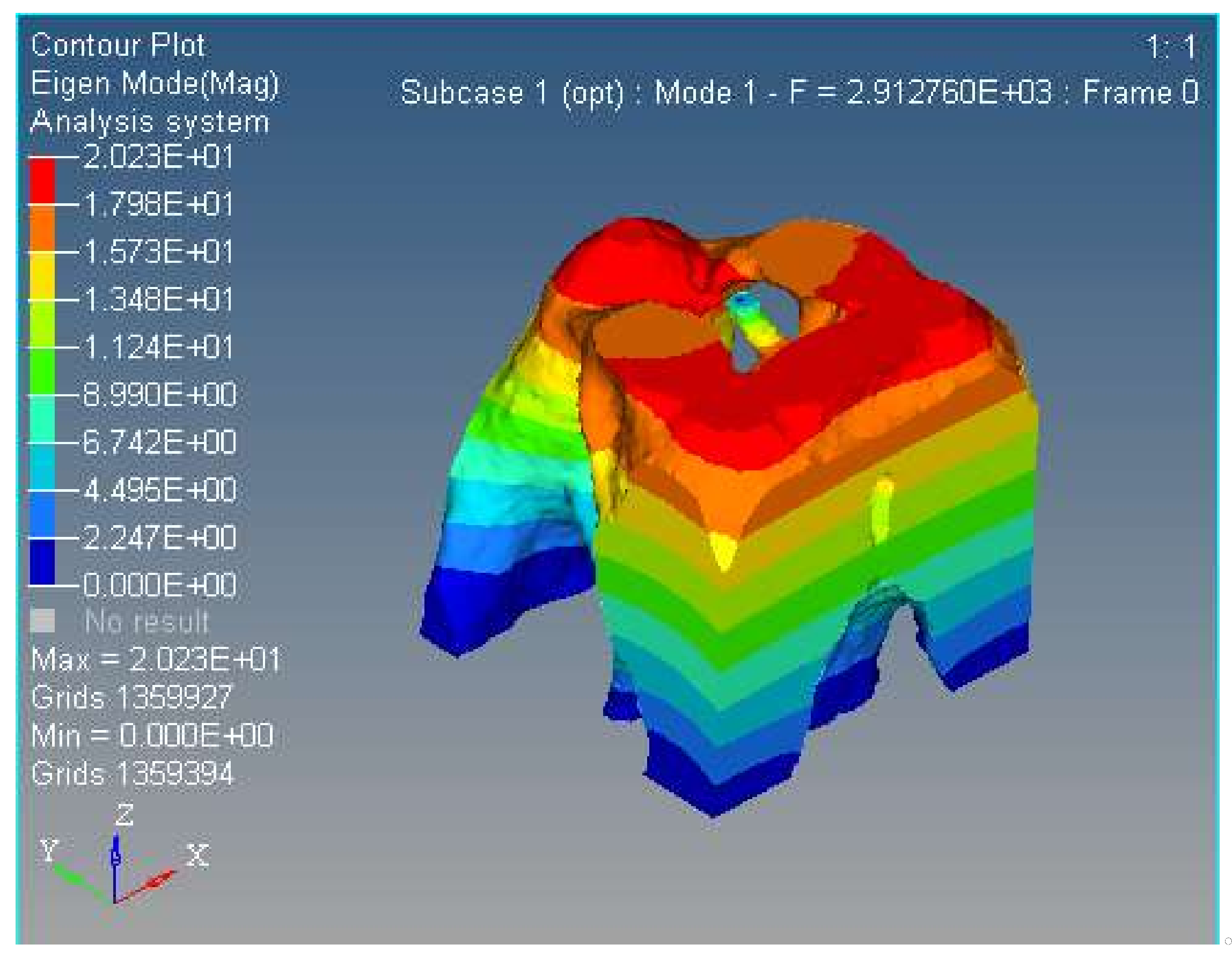
Figure 13.
Second order modal of the proposed spatially compliant mechanism with three rotational DOFs.
Figure 13.
Second order modal of the proposed spatially compliant mechanism with three rotational DOFs.

Table 1.
Structural parameters of the 3-UPC type parallel prototype manipulator.
| Structural Parameters | Values | Output | Values |
|---|---|---|---|
| Length of moving platform | Actuator 1 | ||
| Length of fixed platform | Actuator 2 | ||
| Height | Actuator 3 |
Table 2.
Stress distribution before/after topology optimization.
| Max | Min | |
|---|---|---|
| Before | 8.769 × 10⁻² MPa | 2.152 × 10⁻⁶ MPa |
| After | 8.752 × 10⁻² MPa | 2.983 × 10⁻¹³ Mpa |
Table 3.
The parameters of the piezoelectric (PZT) actuator.
| Terms | Values |
|---|---|
| Model of PZT | PSt150 VS10 |
| Nominal stroke (μm) | 9 ± 10% |
| Stiffness (N/μm) | 50 ± 20% |
| Nominal pull/thrust (N) | 550/100 |
| Electrostatic capacity (μF) | 0.35 ± 20% |
| Resonant frequency (kHz) | 40 |
| Length (mm) | 19 ± 0.3 |
| Driving voltage (V) | 0–120 |
Table 4.
Comparison of the kinematic results between the simulation and experiment.
| Direction | Simulation (maximum) | Experiment (maximum) | Simulation (minimum) | Experiment (minimum) |
|---|---|---|---|---|
| Rotation around -axis | 0.47 × 10⁻⁴ rad | 0.36 × 10⁻⁴ rad | −0.21 × 10⁻⁴ rad | −0.18 × 10⁻⁴ rad |
| Rotation around -axis | 0.51 × 10⁻⁴ rad | 0.39 × 10⁻⁴ rad | −0.46 × 10⁻⁴ rad | −0.12 × 10⁻⁴ rad |
| Rotation around -axis | 0.12 × 10⁻⁴ rad | 0.18 × 10⁻⁴ rad | −0.48 × 10⁻⁵ rad | −0.32 × 10⁻⁴ rad |
© 2018 by the authors. Licensee MDPI, Basel, Switzerland. This article is an open access article distributed under the terms and conditions of the Creative Commons Attribution (CC BY) license (http://creativecommons.org/licenses/by/4.0/).
Share and Cite
MDPI and ACS Style
Zhu, D.; Zhan, W.; Wu, F.; Simeone, A. Topology Optimization of Spatially Compliant Mechanisms with an Isomorphic Matrix of a 3-UPC Type Parallel Prototype Manipulator. Micromachines 2018, 9, 184. https://doi.org/10.3390/mi9040184
AMA Style
Zhu D, Zhan W, Wu F, Simeone A. Topology Optimization of Spatially Compliant Mechanisms with an Isomorphic Matrix of a 3-UPC Type Parallel Prototype Manipulator. Micromachines. 2018; 9(4):184. https://doi.org/10.3390/mi9040184
Chicago/Turabian StyleZhu, Dachang, Wanghu Zhan, Fupei Wu, and Alessandro Simeone. 2018. "Topology Optimization of Spatially Compliant Mechanisms with an Isomorphic Matrix of a 3-UPC Type Parallel Prototype Manipulator" Micromachines 9, no. 4: 184. https://doi.org/10.3390/mi9040184
Note that from the first issue of 2016, this journal uses article numbers instead of page numbers. See further details here.