Parametric Excitation of Optomechanical Resonators by Periodical Modulation


1
School of Mechanical Engineering, Xi’an Jiaotong University, Xi’an 710049, China
2
School of Electrical & Electronic Engineering, Nanyang Technological University, Singapore 639798, Singapore
*
Author to whom correspondence should be addressed.
Micromachines 2018, 9(4), 193; https://doi.org/10.3390/mi9040193
Submission received: 26 February 2018
/
Revised: 4 April 2018
/
Accepted: 17 April 2018
/
Published: 18 April 2018
(This article belongs to the Special Issue Optofluidics: From Fundamental Research to Applications)
Abstract
:Optical excitation of mechanical resonators has long been a research interest, since it has great applications in the physical and engineering field. Previous optomechanical methods rely on the wavelength-dependent, optical anti-damping effects, with the working range limited to the blue-detuning range. In this study, we experimentally demonstrated the excitation of optomechanical resonators by periodical modulation. The wavelength working range was extended from the blue-detuning to red-detuning range. This demonstration will provide a new way to excite mechanical resonators and benefit practical applications, such as optical mass sensors and gyroscopes with an extended working range.
1. Introduction
The ability to optically control mechanical resonators is the key requirement of many technological and fundamental advances in physical and engineering field [1,2,3,4]. The recent development of optomechanics—which utilizes the photon-phonon coupling in nanoscale photonic structures—has provided a new means to manipulate and measure mechanical resonators [5,6,7,8]. The retarded optical force within an optical cavity can be used to cool the mechanical resonators into quantum ground state or to amplify the mechanical resonators into self-oscillation. Recently, several groups have cooled the mechanical motion close to the quantum ground state both in the microwave domain [9] and in the optical domain [10]. For practical applications, optomechanical excitation is attracting more and more attention due to its great technological value. Nowadays, plenty of promising applications have been demonstrated, such as radiofrequency optomechanical resonators [11], nonvolatile optical memory [12], wavelength routing [13], optomechanical sensing [14], and so on.
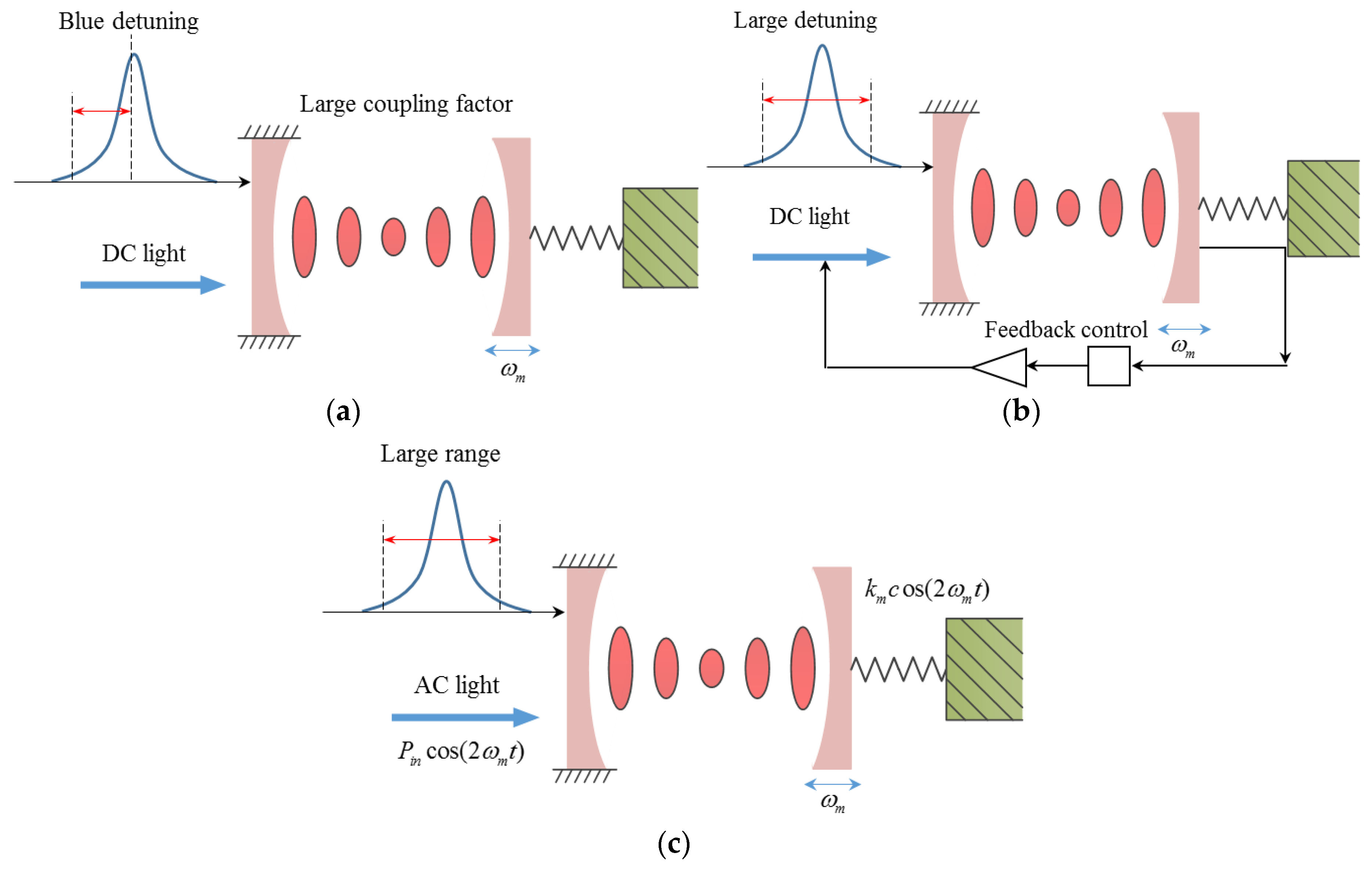
Conventional excitation of optomechanical resonators relies on passive backaction between mechanical resonators and optical cavities [15] or active feedback control [16], which are shown in Figure 1a,b. The optical anti-damping effect is used in the passive backaction method, in which the optical anti-damping is large enough to compensate the intrinsic mechanical damping to excite mechanical resonators [14]. Due to optical anti-damping depending on input optical wavelength, the working range is limited in the blue-detuning range, in which the input wavelength is smaller than the cavity resonance wavelength. Complex off-chip control systems are needed in the active feedback control method, although it can work in the red-detuning range [17,18,19]. From the aspects of device applications, it is desirable to extend the working range in a single chip without complex control systems. Even though manipulating the optomechanical system by an amplitude-modulated light has been proposed both in theory and experiments [20,21,22,23], the parametric excitation has not been demonstrated.
In this study, excitation of optomechanical resonators by periodically modulating optical spring at twice the natural frequency was experimentally demonstrated, which is shown in Figure 1c. This method is achieved by utilizing optical spring rather than optical anti-damping effects. It can break the wavelength limit by extending the working wavelength from the blue-detuning to red-detuning range. This demonstration will provide a new way to excite mechanical resonators and benefit practical applications, such as optical mass sensors and gyroscopes with an extended working range [24,25,26,27].
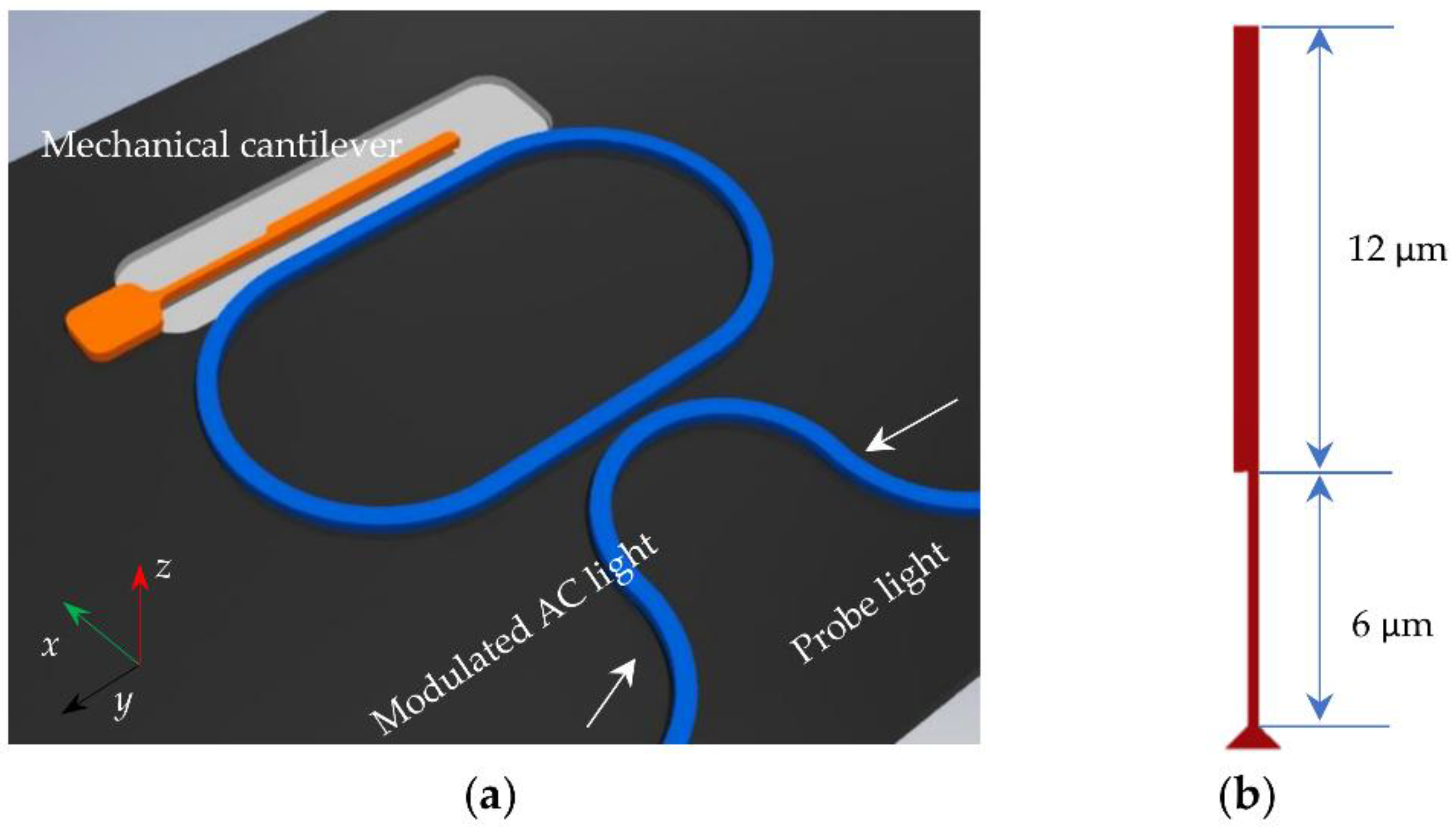
The proposed excitation of optomechanical resonator by periodical modulation consists of a mechanical cantilever, a racetrack optical cavity, and a curved bus waveguide as shown in Figure 2. Mechanical cantilever is located at the side of the racetrack optical cavity with a gap of 200 nm to build optical coupling between cantilever beam and racetrack cavity. The mechanical cantilever is released from the substrate with a gap of 500 nm and can vibrate in the x-direction and z-direction, corresponding to fundamental and second mechanical modes. The mechanical cantilever consists of two parts: one part has a cross-section of 200 nm × 340 nm with a length of 6 µm and the other part has a cross-section of 450 nm × 340 nm with a length of 12 µm. The curved bus waveguide is coupled to the racetrack optical cavity with a gap of 200 nm.
When the pump light is coupled into the racetrack optical cavity through the bus waveguide, optical force due to the evanescent wave overlapping is generated between the mechanical cantilever and racetrack optical cavity. When the pump light is amplitude modulated at twice the mechanical frequency, the alternating optical force will drive the mechanical cantilever and amplify the mechanical vibrations, which are known as parametric excitations.
The pump light was amplitude modulated in the experiment, resulting in the periodical modulation of optical light in the cavity. The intracavity mode amplitude a and the coupled mechanical resonator are described as
where Δ = ω0 − ω is the frequency detuning, ω is the driving laser frequency, ω0 is the optical cavity resonance frequency, gom is the optomechanical coupling, κ is the cavity linewidth, n is the cavity photon number when the detuning is zero , κe is the external cavity linewidth and is the optical input with static power and alternating power , ωm0 is the mechanical frequency, meff is the effective mechanical mass, is the mechanical damping factor, x is the displacement of mechanical resonator.
To simulate the response of the coupled Equations (1) and (2), the equations can be generalized and reduced to
where the frequencies are normalized by , , , , , , , , , is the modulation strength, and is the normalized optomechanical coupling strength.
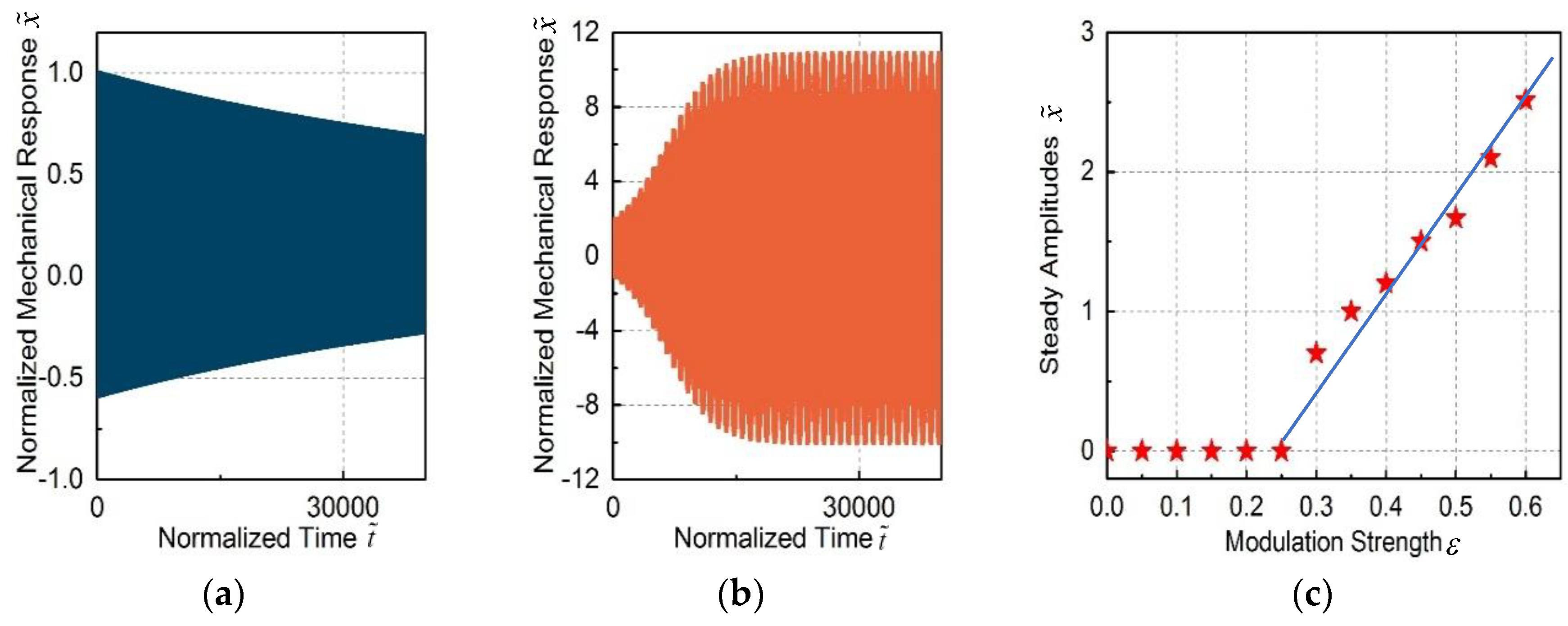
To get the physical insight of this model and simplify the simulation complexity, the parameters are set as , , , , . By setting , Equations (3) and (4) are reduced to the conventional optomechanical coupled oscillators. The simulated response of the mechanical oscillators is shown in Figure 3a, in which the mechanical oscillator is not excited. However, the mechanical oscillator is excited into self-oscillation by setting with other parameters the same, which is shown in Figure 3b. It can be seen that the modulation can effectively excite the mechanical resonators into self-oscillation even though the passive feedback is too small.
The steady response of the mechanical amplitudes as a function of modulation strength is shown in Figure 3c. When the modulation strength is smaller than , the mechanical oscillators are not excited. Above a certain threshold power , the mechanical oscillators are excited into self-oscillation and the amplitudes increase approximately linearly with the modulation strength. This can be explained as follows: as the mechanical oscillation are excited into self-oscillation, the amplitudes are saturated and increase linearly with the power.
2. Fabrication and Experimental Setup
The fabrication process of the optomechanical resonators is described in this section, which is based on the silicon nanophotonic processes [28,29]. The racetrack optical cavity had a footprint of 25 µm × 20 µm and was fabricated in the silicon-on-Insulator (SOI) wafer, which had a 2 µm box layer between the 340 nm silicon structure layer and substrate. The optomechanical resonator was patterned by deep-ultraviolet lithography and followed by plasma dry etching. Note that a hard mask process was adopted to ensure accurate etching because the photoresist is too thick to withstand reactive ion etching [30]. When the etching depth is above 100 nm, the hard mask can help to protect the etching profiles in order to ensure the linewidth and sidewall surface roughness.
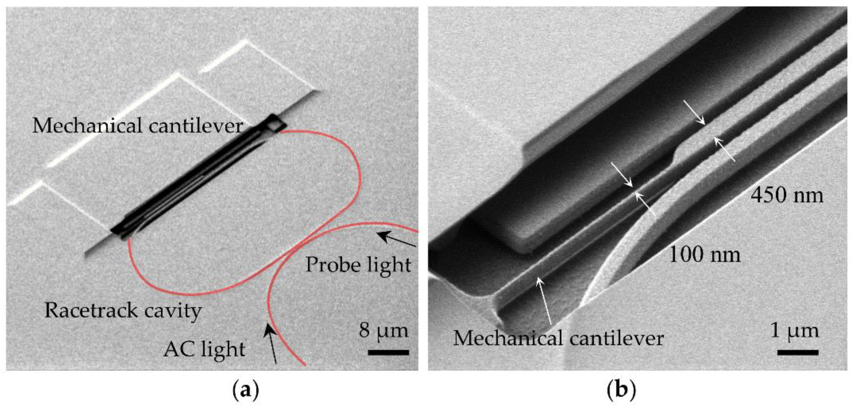
A hard mask made from a 70 nm thin layer of SiO2 was deposited on the surface of wafer by low-temperature plasma-enhanced chemical vapor deposition (PECVD). Subsequently, a 90 nm bottom anti-reflective coating (BARC) and 700 nm photoresist (PR) was dispensed on the surface of the hard mask. The bottom anti-reflective coating is also a must to reduce the standing wave effect from the lithography to ensure the linewidth. Another important issue is the hydrogen fluorider release process, which is used to make the silicon structures movable in the desired directions. The hydrogen fluorider vapor is good choice to release the structures because it only reacts with SiO2 but not with silicon waveguide. These unique characters can leave the etched waveguide with a good profile and a smooth surface without causing the stiction problems. More importantly, the gap between the silicon and substrate can be controlled by choosing different etching times. The etching rate is estimated as 30 nm/min in our structures. A scanning electron microscope (SEM) image of the fabricated device is shown in Figure 4a,b. It should be noted that the estimated width of the fabricated mechanical cantilever is 100 nm, which is smaller than the original design of 200 nm. This is due to imperfect fabrication, such as lithography or etching, in which an unwanted deviation can occur.
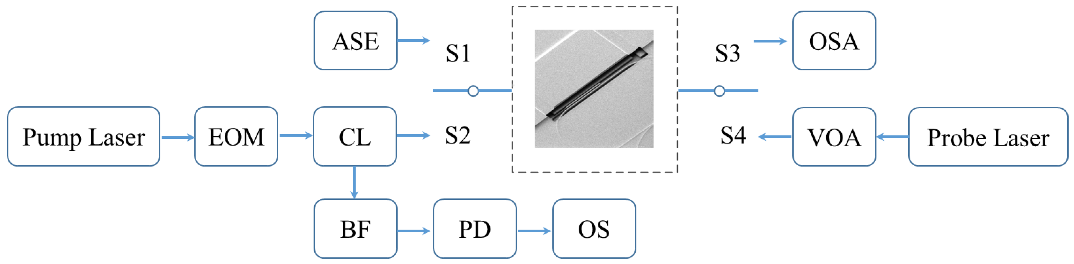
The experimental setup is shown in Figure 5. In the experiment, the probe light was used to measure the mechanical cantilever in the racetrack optical cavity and pumped in a different direction from the pump light to avoid influencing the pump light. The transmission spectrum of the optical cavity was firstly measured by a broadband light from a 12 dBm ASE light source (Amonics ALS-CL-13, Kowloon, Hong Kong, China) and then detected by an optical spectrum analyzer (OSA) (AQ6370D, Yokogawa Test & Measurement Corporation, Tokyo, Japan) by switching S1 and S3. The resolution of the OSA was 0.02 nm. By switching S2 and S4, the mechanical response was measured. The pump light from a tunable laser (Santec TSL 510, Hackensack, NJ, USA) was modulated by an electrical-optical modulator and the frequency was controlled by a programmable function generator (PM 5193, Philips, Amsterdam, The Netherlands). The power of the probe light from a tunable laser (Santec TSL 510, Hackensack, NJ, USA) was controlled by the variable optical attenuator. The probe light was separated from the pump light by the bandpass filter and was received by the photodetector (FPD 510, Menlo Systems GmbH, Planegg, Germany), in which the power spectral density of the mechanical oscillation in the frequency domain and time domain was shown in the oscilloscope (MDO4104B-3, Tektronix, Inc., Beaverton, OR, USA). The device was measured under a high-vacuum chamber (2 × 10⁻⁶ mBar).
3. Experimental Results and Discussions
3.1. Optical Characterization of the Racetrack Optical Cavity
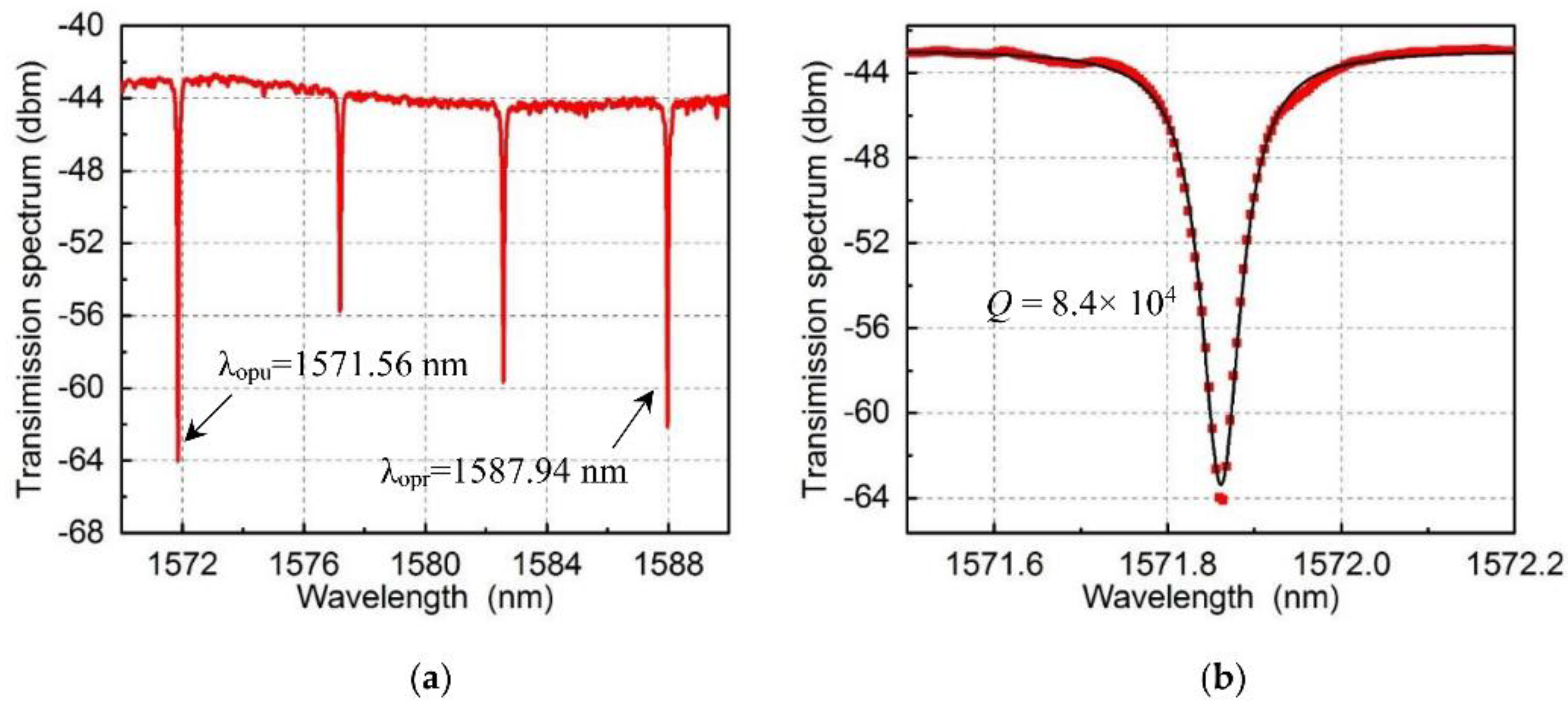
In the experiment, the transmission spectrum of the racetrack resonator was firstly characterized by a low-power broadband light. Figure 6a shows the output light from the grating coupler.
The optical resonance wavelength was separated by the free spectral range (FSR) with a range of 5.34 nm. In order to separate the pump and probe light, resonance wavelength at 1571.86 nm was used as the pump light channel and resonance wavelength at 1587.94 nm was used as the probe light channel. The transmission spectrum at 1571.86 nm with a Lorenz fitting is shown in Figure 6b. The optical quality factor is 8.4 × 10⁴ with a dip of 20 dB.
3.2. Optical Characterization of the Mechanical Cantilever
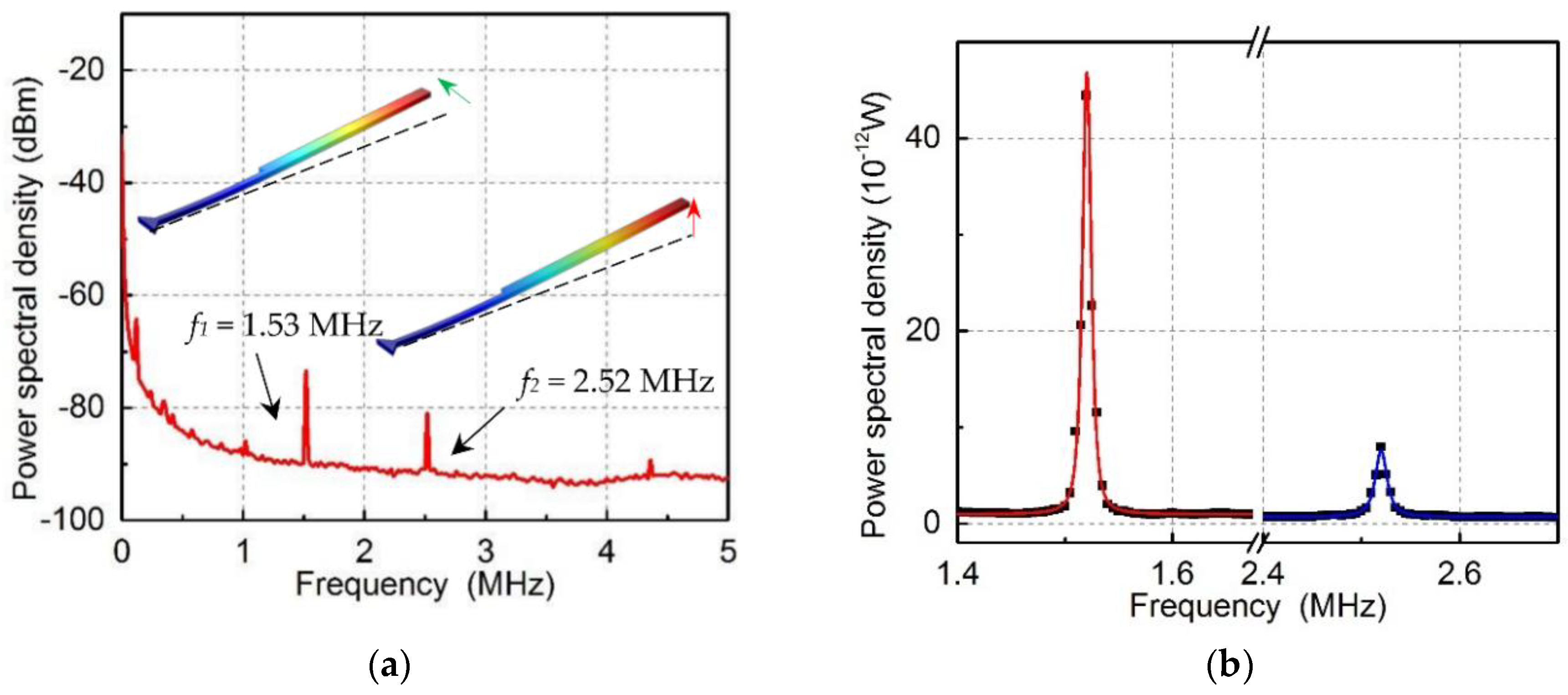
After the characterization of the optical racetrack cavity, another important issue is to characterize the vibration mode of the mechanical cantilever. In the experiment, a probe light with a power of 20 µW at wavelength λpr = 1587.90 nm was coupled to the cavity and the output light was analyzed by the oscilloscope. The power spectral density of the mechanical motion is shown in Figure 7. Since the mechanical cantilever can vibrate in the x and z direction, two mechanical modes are 1.53 MHz with mechanical linewidth of 1 kHz, and 2.52 MHz with mechanical linewidth of 1.5 kHz, respectively. The finite element simulation of the mechanical modes is shown in the inset figures. It should be noted that the residual stress due to the fabrication will result in a shift of the practical mechanical resonance frequency.
3.3. Excitation of the Mechanical Cantilever
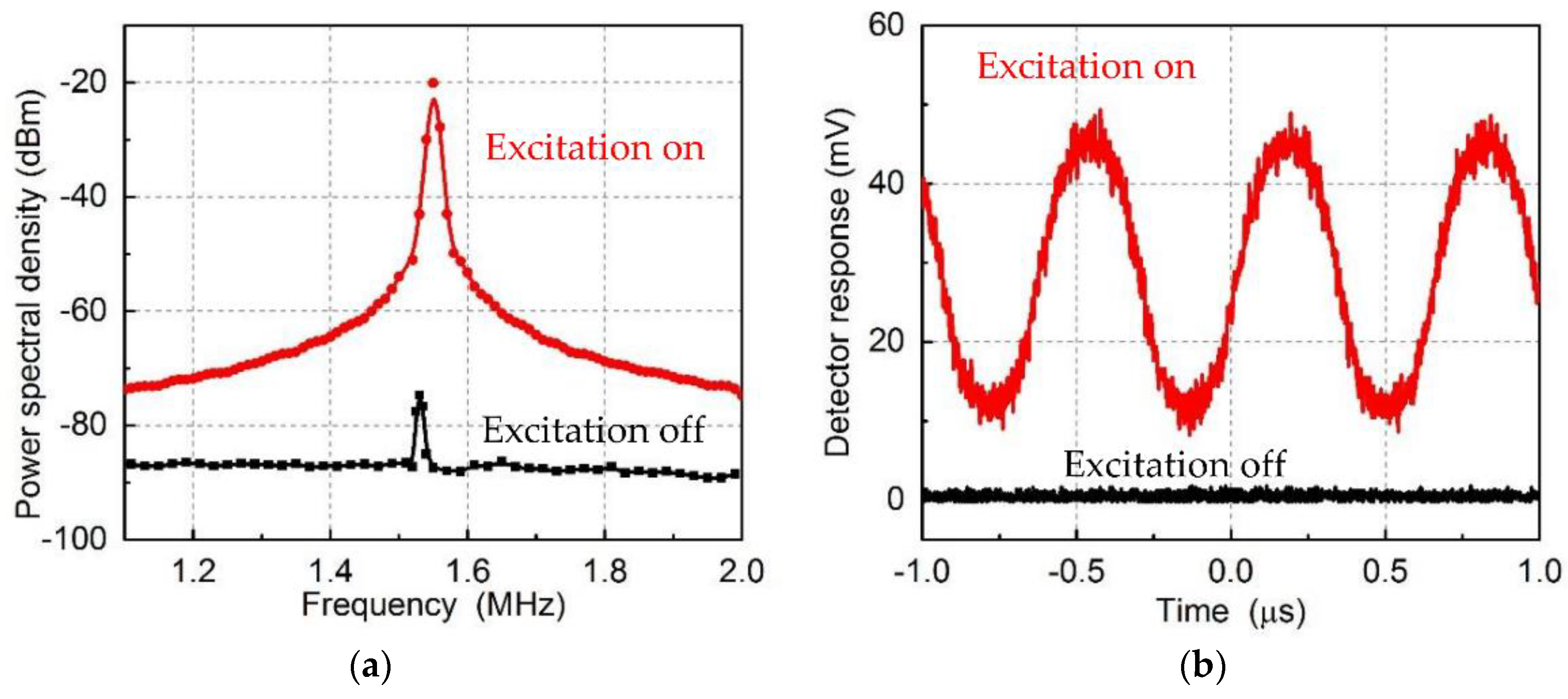
In order to demonstrate the parametric excitation of mechanical cantilever, a modulated pump light with a power of 200 µW at wavelength λpu = 1571.50 nm was coupled to the racetrack optical cavity to excite the mechanical cantilever. When the modulated frequency is twice the mechanical frequency ωp/2π = 3.06 MHz, the mechanical cantilever is excited, which is shown in Figure 8a. The black and red curve shows the original thermal mechanical vibrations and amplified vibrations separately. It can be seen that the power spectral density is greatly excited from −79 dBm to −20 dBm. This excitation can also be demonstrated in the time domain, which is shown in Figure 8b, in which the mechanical cantilever is excited by the pump light. The peak in Figure 8a is −25 dBm, which corresponds to 12.5 mV rms (35 mV pp) in Figure 8b. The peak in black curves is thermal motion of the cantilever.
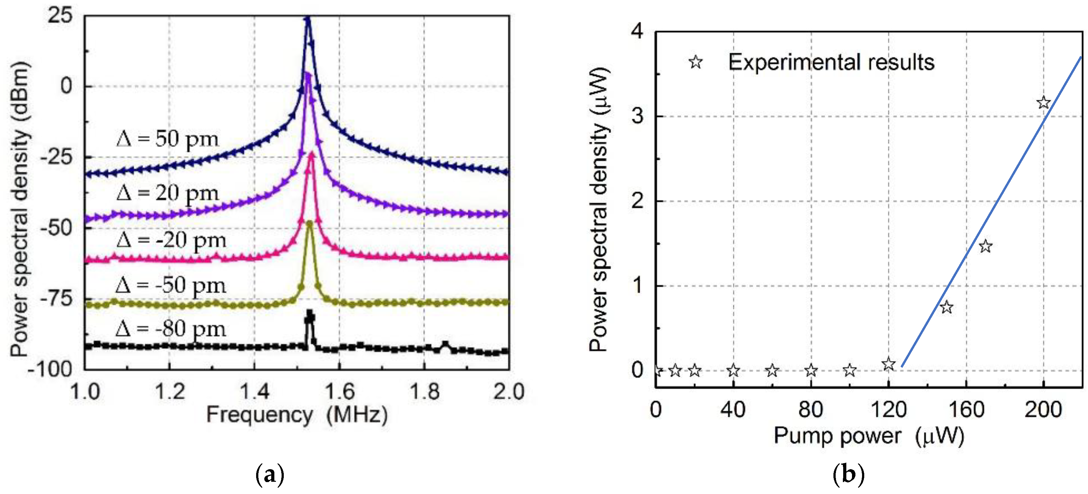
Then, the wavelength of the pump light was changed to demonstrate the extended working range. The detuning of the pump light Δ = λpu − λopu was swept from −80 pm to 50 pm at fixed a power of 200 µW to observe the parametric excitation, which is shown in Figure 9a. It can be seen that the working range is extended from the blue-detuning to red-detuning region with a range of 130 pm. At the same time, increasing the modulation strength can enhance the excitation. In the experiment, the power of the pump light was gradually increased from 0 to 200 µW at fixed −60 pm to observe the effect of the modulation strength on the excitation. The detailed experimental results are shown in Figure 9a. It should be noted that the results shown in Figure 9a,b were obtained in different conditions: one is for fixed optical power, while the other one is for fixed optical wavelength. By increasing the power of pump light, the mechanical motion was gradually amplified. The relationship between the peak value and the pump power is shown in Figure 9b with a fitting curve. Even though amplitudes increase with the optical power, larger optical power will result in the instability of the system due to the thermo-optical effects of the silicon structures. The largest amplitude of the mechanical oscillator is estimated as 5 nm. Since the optomechanical coupling factor is gom/2π = 450 MHz/nm, the cavity frequency shift is 2π × 2.25 GHz, which is comparable to the cavity linewidth 2π × 2.27 GHz.
It can be seen from Figure 9b that the power spectral densities are not linear with the optical power. Here, we give a rough explanation for this nonlinearity. When the mechanical oscillators are excited, the mechanical nonlinearity starts to play a role. In particular, our theoretical simulation is based on small linear approximation, so when the mechanical oscillation is large, the nonlinearity [31,32] should be taken into account.
4. Conclusions
In this study, the excitation of optomechanical resonators by periodical modulation was experimentally demonstrated. A mechanical cantilever is excited by the modulated optical field in an optical resonator with an optical quality factor of 8.43 × 10⁴. The working wavelength of the pump light is extended from blue-detuning to red-detuning region with a range of 130 pm. The excitation is enhanced by increasing the optical power. Compared with conventional mechanical excitation induced by the passive back action or active feedback control, this method provides a simple and effective approach [33,34,35]. This demonstration will benefit the optical mass sensor based on the parametric excitation and be useful for improving performance in practical applications, such as gyroscopes with an extended working range.
Acknowledgments
This work was supported by Singapore National Research Foundation under the Incentive for Research & Innovation Scheme (1102-IRIS-05-01) administered by PUB, and under the Competitive Research Program (NRF-CRP13-2014-01).
Author Contributions
J.H. and A.L. jointly conceived the idea of this study. J.H. fabricated the devices. J.H. and M.F.K. performed the theoretical simulations. J.H. performed the measurements with the suggestions of J.W. and T.C., J.H. and A.L. analyzed the results. J.H. and A.L. prepared the manuscript. All authors discussed the results and commented on the manuscript.
Conflicts of Interest
The authors declare no conflict of interest.
References
- Accadia, T.; Acernese, F.; Alshourbagy, M.; Amico, P.; Antonucci, F.; Aoudia, S.; Arnaud, N.; Arnault, C.; Arun, K.; Astone, P. Virgo: A laser interferometer to detect gravitational waves. J. Instrum. 2012, 7, P03012. [Google Scholar] [CrossRef]
- Pirkkalainen, J.-M.; Damskägg, E.; Brandt, M.; Massel, F.; Sillanpää, M. Squeezing of quantum noise of motion in a micromechanical resonator. Phys. Rev. Lett. 2015, 115, 243601. [Google Scholar] [CrossRef] [PubMed]
- Rocheleau, T.; Ndukum, T.; Macklin, C.; Hertzberg, J.; Clerk, A.; Schwab, K. Preparation and detection of a mechanical resonator near the ground state of motion. Nature 2010, 463, 72–75. [Google Scholar] [CrossRef] [PubMed]
- Weiss, T.; Nunnenkamp, A. Quantum limit of laser cooling in dispersively and dissipatively coupled optomechanical systems. Phys. Rev. A 2013, 88, 023850. [Google Scholar] [CrossRef]
- Li, M.; Pernice, W.; Xiong, C.; Baehr-Jones, T.; Hochberg, M.; Tang, H. Harnessing optical forces in integrated photonic circuits. Nature 2008, 456, 480–484. [Google Scholar] [CrossRef] [PubMed]
- Ren, M.; Huang, J.; Cai, H.; Tsai, J.M.; Zhou, J.; Liu, Z.; Suo, Z.; Liu, A.-Q. Nano-optomechanical actuator and pull-back instability. ACS Nano 2013, 7, 1676–1681. [Google Scholar] [CrossRef] [PubMed]
- Singh, V.; Bosman, S.; Schneider, B.; Blanter, Y.M.; Castellanos-Gomez, A.; Steele, G. Optomechanical coupling between a multilayer graphene mechanical resonator and a superconducting microwave cavity. Nat. Nanotechnol. 2014, 9, 820–824. [Google Scholar] [CrossRef] [PubMed]
- Weis, S.; Rivière, R.; Deléglise, S.; Gavartin, E.; Arcizet, O.; Schliesser, A.; Kippenberg, T.J. Optomechanically induced transparency. Science 2010, 330, 1520–1523. [Google Scholar] [CrossRef] [PubMed]
- Teufel, J.; Donner, T.; Li, D.; Harlow, J.; Allman, M.; Cicak, K.; Sirois, A.; Whittaker, J.D.; Lehnert, K.; Simmonds, R.W. Sideband cooling of micromechanical motion to the quantum ground state. Nature 2011, 475, 359. [Google Scholar] [CrossRef] [PubMed]
- Chan, J.; Alegre, T.M.; Safavi-Naeini, A.H.; Hill, J.T.; Krause, A.; Gröblacher, S.; Aspelmeyer, M.; Painter, O. Laser cooling of a nanomechanical oscillator into its quantum ground state. Nature 2011, 478, 89. [Google Scholar] [CrossRef] [PubMed]
- Schliesser, A.; Kippenberg, T.J. Cavity optomechanics with whispering-gallery mode optical micro-resonators. Adv. Atomic Mol. Opt. Phys. 2010, 58, 207–323. [Google Scholar]
- Bagheri, M.; Poot, M.; Li, M.; Pernice, W.P.; Tang, H.X. Dynamic manipulation of nanomechanical resonators in the high-amplitude regime and non-volatile mechanical memory operation. Nat. Nanotechnol. 2011, 6, 726–732. [Google Scholar] [CrossRef] [PubMed]
- Rosenberg, J.; Lin, Q.; Painter, O. Static and dynamic wavelength routing via the gradient optical force. Nat. Photon. 2009, 3, 478–483. [Google Scholar] [CrossRef]
- Miao, H.; Srinivasan, K.; Aksyuk, V. A microelectromechanically controlled cavity optomechanical sensing system. New J. Phys. 2012, 14, 075015. [Google Scholar] [CrossRef]
- Jayich, A.; Sankey, J.; Zwickl, B.; Yang, C.; Thompson, J.; Girvin, S.; Clerk, A.; Marquardt, F.; Harris, J. Dispersive optomechanics: A membrane inside a cavity. New J. Phys. 2008, 10, 095008. [Google Scholar] [CrossRef]
- Zhang, J.; Liu, Y.-X.; Nori, F. Cooling and squeezing the fluctuations of a nanomechanical beam by indirect quantum feedback control. Phys. Rev. A 2009, 79, 052102. [Google Scholar] [CrossRef]
- Chang, D.E.; Regal, C.; Papp, S.; Wilson, D.; Ye, J.; Painter, O.; Kimble, H.J.; Zoller, P. Cavity opto-mechanics using an optically levitated nanosphere. Proc. Natl. Acad. Sci. USA 2010, 107, 1005–1010. [Google Scholar] [CrossRef] [PubMed]
- Elste, F.; Girvin, S.; Clerk, A. Quantum noise interference and backaction cooling in cavity nanomechanics. Phys. Rev. Lett. 2009, 102, 207209. [Google Scholar] [CrossRef] [PubMed]
- Navarro-Urrios, D.; Capuj, N.E.; Gomis-Bresco, J.; Alzina, F.; Pitanti, A.; Griol, A.; Martinez, A.; Torres, C.S. A self-stabilized coherent phonon source driven by optical forces. Sci. Rep. 2015, 5, 15733. [Google Scholar] [CrossRef] [PubMed]
- Mari, A.; Eisert, J. Gently modulating optomechanical systems. Phys. Rev. Lett. 2009, 103, 213603. [Google Scholar] [CrossRef] [PubMed]
- Tan, H.; Li, G.; Meystre, P. Dissipation-driven two-mode mechanical squeezed states in optomechanical systems. Phys. Rev. A 2013, 87, 033829. [Google Scholar] [CrossRef]
- Ramos, D.; Mertens, J.; Calleja, M.; Tamayo, J. Phototermal self-excitation of nanomechanical resonators in liquids. Appl. Phys. Lett. 2008, 92, 173108. [Google Scholar] [CrossRef]
- Deotare, P.B.; Bulu, I.; Frank, I.W.; Quan, Q.; Zhang, Y.; Ilic, R.; Loncar, M. All optical reconfiguration of optomechanical filters. Nat. Commun. 2012, 3, 846. [Google Scholar] [CrossRef] [PubMed]
- Groenesteijn, J.; Droogendijk, H.; Wiegerink, R.J.; Lammerink, T.S.; Lötters, J.C.; Sanders, R.G.; Krijnen, G.J. Parametric amplification in a micro coriolis mass flow sensor. J. Appl. Phys. 2014, 115, 194503. [Google Scholar] [CrossRef]
- Cleland, A.N. Thermomechanical noise limits on parametric sensing with nanomechanical resonators. New J. Phys. 2005, 7, 235. [Google Scholar] [CrossRef]
- Sharma, M.; Sarraf, E.H.; Cretu, E. Parametric amplification/damping in MEMS gyroscopes. In Proceedings of the 2011 IEEE 24th International Conference on Micro Electro Mechanical Systems (MEMS), Cancun, Mexico, 23–27 January 2011; pp. 617–620. [Google Scholar]
- Gallacher, B.; Burdess, J.; Harish, K. A control scheme for a MEMS electrostatic resonant gyroscope excited using combined parametric excitation and harmonic forcing. J. Micromech. Microeng. 2006, 16, 320. [Google Scholar] [CrossRef]
- Dong, B.; Cai, H.; Chin, L.K.; Huang, J.; Yang, Z.; Gu, Y.; Ng, G.I.; Ser, W.; Kwong, D.; Liu, A.Q. A silicon-nanowire memory driven by optical gradient force induced bistability. Appl. Phys. Lett. 2015, 107, 261111. [Google Scholar] [CrossRef]
- Ren, M.; Cai, H.; Chin, L.K.; Huang, J.; Gu, Y.; Radhakrishnan, K.; Ser, W.; Liu, A.Q. An opto-mechanical coupled-ring reflector driven by optical force for lasing wavelength control. Appl. Phys. Lett. 2016, 108, 081106. [Google Scholar] [CrossRef]
- Yu, Y.; Zhang, J.; Bourouina, T.; Liu, A. Optical-force-induced bistability in nanomachined ring resonator systems. Appl. Phys. Lett. 2012, 100, 093108. [Google Scholar] [CrossRef]
- Sankey, J.C.; Yang, C.; Zwickl, B.M.; Jayich, A.M.; Harris, J.G. Strong and tunable nonlinear optomechanical coupling in a low-loss system. Nat. Phys. 2010, 6, 707. [Google Scholar] [CrossRef]
- Leijssen, R.; La Gala, G.R.; Freisem, L.; Muhonen, J.T.; Verhagen, E. Nonlinear cavity optomechanics with nanomechanical thermal fluctuations. Nat. Commun. 2017, 8. [Google Scholar] [CrossRef] [PubMed]
- Karabalin, R.; Cross, M.; Roukes, M. Nonlinear dynamics and chaos in two coupled nanomechanical resonators. Phys. Rev. B 2009, 79, 165309. [Google Scholar] [CrossRef]
- Kozinsky, I.; Postma, H.C.; Bargatin, I.; Roukes, M. Tuning nonlinearity, dynamic range, and frequency of nanomechanical resonators. Appl. Phys. Lett. 2006, 88, 253101. [Google Scholar] [CrossRef]
- Lemonde, M.-A.; Didier, N.; Clerk, A.A. Nonlinear interaction effects in a strongly driven optomechanical cavity. Phys. Rev. Lett. 2013, 111, 053602. [Google Scholar] [CrossRef] [PubMed]
Figure 1.
Schematic of different methods for excitation of optomechanical resonators. (a) Passive backaction between cavity and mechanical cantilever by direct current (DC) light using optical anti-damping effect; (b) active feedback control by DC light using optical anti-damping effect; (c) modulated light at twice the mechanical frequency using optical spring effect.

Figure 2.
(a) The schematic illustration of modulated method by alternating current (AC) light using optical spring effect for mechanical excitation; (b) the size of mechanical cantilever.
Figure 2.
(a) The schematic illustration of modulated method by alternating current (AC) light using optical spring effect for mechanical excitation; (b) the size of mechanical cantilever.

Figure 3.
The theoretical simulation of the normalized mechanical response under the periodical modulation. (a) The mechanical oscillator is not excited at ε = 0; (b) the mechanical oscillator is excited at ε = 1; (c) the steady amplitudes as a function of the modulation strength.
Figure 3.
The theoretical simulation of the normalized mechanical response under the periodical modulation. (a) The mechanical oscillator is not excited at ε = 0; (b) the mechanical oscillator is excited at ε = 1; (c) the steady amplitudes as a function of the modulation strength.

Figure 4.
(a) scanning electron microscope (SEM) image of the fabricated device; (b) zoom-in view with the width labeled.
Figure 4.
(a) scanning electron microscope (SEM) image of the fabricated device; (b) zoom-in view with the width labeled.

Figure 5.
The schematic of the experimental setup. Abbreviations: EOM, electro-optical modulator; CL, optical circulator; VOA, variable optical attenuator; BF, bandpass filter; PD, photon detector; OS, oscilloscope; ASE, amplified spontaneous emission light; OSA, optical spectrum analyzer; S1–S4, optical switch.

Figure 6.
(a) Transmission spectrum of the optical racetrack cavity showing resonance at different optical wavelengths. Resonance wavelength at 1571.86 nm was used as the pump light channel and resonance wavelength at 1587.94 nm was used as the probe light channel. (b) The zoom-in transmission spectrum at 1571.86 nm with a Lorenz fitting, which shows the optical quality factor, is Q = 8.4 × 10⁴.

Figure 7.
(a) The power spectral density of the measured signals, showing the mechanical vibration motions. The inset is the finite element simulation of the two mechanical vibration modes, which correspond to x and z direction. (b) The zoom-in power spectrum density of two mechanical oscillators.
Figure 7.
(a) The power spectral density of the measured signals, showing the mechanical vibration motions. The inset is the finite element simulation of the two mechanical vibration modes, which correspond to x and z direction. (b) The zoom-in power spectrum density of two mechanical oscillators.

Figure 8.
(a) The power spectral density of the measured signals, showing the thermal mechanical noise (black curve) and amplified mechanical motions (red curve) when the pump light is in the state of off and on separately; (b) the time domain traces showing the original mechanical vibrations and amplified vibrations separately.

Figure 9.
(a) The power spectral density of the measured signals when the wavelength detuning is from −80 pm to 50 pm (curves are vertically offset for clarification); (b) the peak value of power spectral density at the mechanical resonance frequency versus the pump power.
Figure 9.
(a) The power spectral density of the measured signals when the wavelength detuning is from −80 pm to 50 pm (curves are vertically offset for clarification); (b) the peak value of power spectral density at the mechanical resonance frequency versus the pump power.

© 2018 by the authors. Licensee MDPI, Basel, Switzerland. This article is an open access article distributed under the terms and conditions of the Creative Commons Attribution (CC BY) license (http://creativecommons.org/licenses/by/4.0/).
Share and Cite
MDPI and ACS Style
Huang, J.; Karim, M.F.; Wu, J.; Chen, T.; Liu, A. Parametric Excitation of Optomechanical Resonators by Periodical Modulation. Micromachines 2018, 9, 193. https://doi.org/10.3390/mi9040193
AMA Style
Huang J, Karim MF, Wu J, Chen T, Liu A. Parametric Excitation of Optomechanical Resonators by Periodical Modulation. Micromachines. 2018; 9(4):193. https://doi.org/10.3390/mi9040193
Chicago/Turabian StyleHuang, Jianguo, Muhammad Faeyz Karim, Jiuhui Wu, Tianning Chen, and Aiqun Liu. 2018. "Parametric Excitation of Optomechanical Resonators by Periodical Modulation" Micromachines 9, no. 4: 193. https://doi.org/10.3390/mi9040193
Note that from the first issue of 2016, this journal uses article numbers instead of page numbers. See further details here.