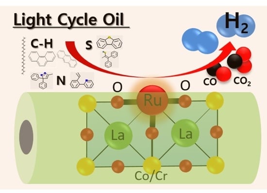
Light Cycle Oil Source for Hydrogen Production through Autothermal Reforming using Ruthenium doped Perovskite Catalysts

1
Department of Environmental Engineering, Yonsei University, 1 Yonsei-gil, Wonju, Gangwon-do 26493, Korea
2
Department of Chemical & Biological Engineering, Hanbat National University, Daejeon 34158, Korea
3
Department of Chemical and Biomolecular Engineering, Yonsei University, 50 Yonsei-ro, Seodaemun-gu, Seoul 03722, Korea
*
Authors to whom correspondence should be addressed.
Catalysts 2020, 10(9), 1039; https://doi.org/10.3390/catal10091039
Submission received: 15 August 2020
/
Revised: 2 September 2020
/
Accepted: 8 September 2020
/
Published: 10 September 2020
(This article belongs to the Special Issue Nanocatalysts for Hydrogen Production)
Abstract
:As the hydrogen economy is coming soon, the development of an efficient H2 production system is the first issue to focus on. In this study, a first attempt to utilize light cycle oil (LCO) feedstock is introduced for H2 production through autothermal reforming (ATR) using perovskite catalysts. From a careful characterization, it is found that LCO possesses a high content of C–H and S/N compounds with over 3–4 ring bonds. These various compounds can directly cause catalyst deactivations to lower the capability of H2 extraction from LCO. To achieve a heteroatom resistance, two different perovskite micro-tubular catalysts are designed with a Ru substitution at the B-site. The activity and stability of the Ru doped perovskite were controlled by modifying the Ru electronic structure, which also affects the oxygen structures. The perovskite with a B-site of Cr reveals a relatively high portion of active Ru and O, demonstrating an effective catalyst structure with a comparable LCO reforming activity at the harsh ATR reaction conditions. The greater stability due to the Ru in the perovskite is investigated post-characterization, showing the possibility of H2 production by LCO fuel through the perovskite catalysts.
1. Introduction
The high demand for a new energy source has risen for many years, due to the limited amount of carbon-based sources that also cause severe environmental pollution by combustion [1,2]. The Paris Agreement was agreed under the United Nations Framework Convention on Climate Change (UNFCCC) between over 190 countries to be prepared for the severe climate change [3,4,5]. The goal of this agreement is to limit the global warming to 2 °C (and even 1.5 °C) at above pre-industrial levels by 2100 [6,7,8]. To achieve this goal, the international society is focusing on reducing the emission of the greenhouse gas (GHG) by a quick or large scale decarbonization system in all sectors of their economies. There are many decarbonization scenarios that have come out so far, but it is important to change to a new energy paradigm, which runs by an efficient and sustainable alternative energy source for the all sectors of the economy [8,9]. Hydrogen is foreseen to play a major role as a clean and potentially sustainable energy carrier, feedstock and fuel for applying to heating, industry, transportation and any other systems [7,8,9,10,11]. Therefore, a huge demand for hydrogen has recently increased, due to the expansion of the hydrogen-based society.
So far, more than 95% of hydrogen is produced by the reforming of fossil fuels, mainly to natural gas due to its high energy efficiency and practicality as a transition toward high technology [8,12,13,14]. Heavy-hydrocarbon sources, such as diesel and gasoline etc., have been recognized as a practical feedstock for establishing an efficient H2 infrastructure, because of its rich H2 content with high volumetric/gravimetric energy densities, easy storage and transport with a great accessibility [15,16,17]. To extract H2 from a heavy-hydrocarbon feed, it is reported that autothermal reforming (ATR), a combination of partial oxidation and steam reforming reactions, is effective due to its great cracking ability with low coke formation, high H2 yields and fast reaction start-up, etc. [18,19]. This technology has been expanded to various studies using different feedstock like gas oil, bio-oil and biomass, etc. [15,20,21].
Light cycle oil (LCO) is a middle distillate product of the fractionation of fuel catalytic cracking (FCC) reactor effluent [22,23]. Generally, LCO is the low-quality feedstock within the range of the distillation and viscosity (similar molecular structure) for diesel fuel production, since LCO is difficult to upgrade in conventional hydrotreating units. When directly using LCO, it is a poor diesel fuel blending component due to a poor performance of the engine ignition from a low cetane number and high density. The main application is its usage as a viscosity cutter for reducing the final viscosity of heavy residual fuel [24]. Therefore, in this study, a first attempt to directly utilize LCO as a feedstock for hydrogen production under autothermal reforming with a heteroatom-resistant catalyst is introduced. It has advantages for infrastructural reasons, and especially for the economical price of the starting feeds without any pretreatment processes [15,20]. Basically, LCO contains a high C/H atomic ratio and high concentration of the refractory sulfur species and N compounds. Such severe operating conditions are a concern when designing catalysts, because these kinds of hetero-atoms can decrease its stability caused by an agglomeration of the metal active sites, carbon coking and sulfur poisoning. Noble metals (Pt, Rh, Ru, and Pd etc.) deposited onto supports, are typically used as a conventional catalyst, but these are not free from the deactivation under such conditions due to the exposure of the active sites directly to hetero-atoms [25,26,27]. Nevertheless, LCO is an attractive feedstock in order to be commercially viable for H2 production. No studies on the reforming process by LCO have been reported, hence a highly active and stable catalysts under high S, N conditions need to be developed.
Perovskite structured materials have been catalyst candidates for H2 production due to their stability at high temperature, H2-rich and redox environments [28,29,30]. Moreover, a good resistant to coke deposition and low chemical binding energy with sulphur are suitable for the suggested LCO reforming. With the formula ABO3, the B cation is believed to be responsible for the catalytic activity. It is possible to stabilize an active cation by partial substitution of B-sites, and further improve the activity/stability by the change of the perovskite structure and electronic configuration [31,32,33,34]. The metal doping can modify the perovskite oxide structure which could increase the surface active oxygen and reducibility at the same time, for higher activity in a autothermal reaction conditions [17]. Moreover, the metal substituted in the perovskite framework is trapped stably by the synergy effect with the surrounded active oxygen, resulting in a relatively high stability in even a very harsh reaction conditions. Therefore, doped perovskite catalysts can be suitable to chemical reactions at complicated operating conditions, especially H2 production from heavy-hydrocarbon feedstock. However, there are no studies reported on such catalyst systems at the LCO reforming reaction.
Here, LCO-ATR reactions for economical H2 production are carried out under Ru doped perovskite catalysts with a micro-tubular morphology. The feedstock of LCO is characterized by the gas chromatography-atomic emission (GC-AED) to investigate the C/H atomic ratio, the concentration of the refractory sulfur species and N compounds. Two different perovskite catalysts are synthesized by the activated carbon fiber (ACF) template method to produce a hollow fibrous feature for higher surface area and mass/heat transfer [16,17,20]. A comparable amount of Ru with Pt is substituted into the B-site of LaCoO3 and LaCrO3. The prepared catalysts were characterized by SEM-EDX, XRD and XANES to investigate the structural difference. The activities of the designed perovskite catalysts were then measured at various temperature and each stability was compared in terms of the LCO composition to the gas products, carbon coking and sulfur poisoning after LCO-ATR reactions to understand the mechanism.
2. Results and Discussion
2.1. LCO Feedstock Characterization
In Figure 1, the carbon, sulfur, and nitrogen contents of the LCO feedstock, analyzed using gas chromatography-atomic emission detection (GC-AED) hyphenated with a high temperature injector system (HT GC-AED) are demonstrated. The LCO contained hydrocarbons in the range of C10 to C22 as well as 35,694 ppm sulfur and 1177 ppm nitrogen. Moreover, the sulfur chromatogram indicated that LCO contained 16,839 ppm of sulfur as the reactive sulfur species and 18,854 ppm of sulfur as the refractory sulfur species.
In order to observe the molecular range, the as-received LCO were also analyzed by using two-dimensional gas chromatography coupled with time-of-flight mass spectrometry (2D GC-ToF MS). Various compounds, including hydrocarbon, sulfur and nitrogen species, in the samples were classified in Table 1 into family groups according to their chemical structures, such as ring numbers and saturation, for easily discussing their reactivities over reforming catalysts. Figure 1a shows the C–H chromatogram to analyze the HC composition in the LCO feed. It was found that a relatively low quantity of around 55% was C–H compounds, indicating the high content of sulfur and nitrogen compounds. This value can be directly correlated to the total H2 yield when LCO is applied to a reforming reaction. Most of hydrocarbon species (CxHy) were located in 2- or 3-ring compounds, from the list of the C–H compounds in Table 1. The compounds with 2–3 rings show a relatively high content of 42 wt % while around 10% of the compounds with no rings was detected, meaning hard ring opening is a crucial point to achieve the reforming reaction. The nitrogen chromatogram in Figure 1b revealed that the nitrogen-containing species in the LCO feedstock mostly consisted of unsubstituted, mono- and dialkyl-carbazoles with a total nitrogen content of 1176 ppm. This level of nitrogen can adversely affect the performance of catalytic ring-opening and other hydrotreating process. The as-received information on the aromatic and nonaromatic contents of LCO were 73 and 27 wt %, respectively.
Among the aromatic hydrocarbons, diaromatics (49 wt %) and triaromatics (34 wt %) were predominant with small contents of monoaromatics (6 wt %) and polyaromatics (compounds with four or more rings, 11 wt %). As shown in Figure 1c, the value of the sulfur species is in total of over 30% in the LCO compositions, which is a very high concentration comparing to other heavy-hydrocarbon feeds such as diesel, gasoline and even gas-oils [15,16,17,20]. This large amount of sulfur species will affect to a deactivation of the catalysts during the LCO reforming reaction, showing the necessity of the stable catalyst development. Therefore, a higher content of S and N species neighboring with 2–3 ring compounds has been led to usage of heteroatom resisted catalyst type such as perovskite form.
2.2. Synthesis of Perovskite Catalysts
To produce hydrogen from a heavy-hydrocarbon source of LCO, perovskite based micro-tubular catalysts are designed due to a relatively high surface area and efficient mass transfer for a high contact time and short diffusion of the reactants in the autothermal reforming system. The microtubular feature was obtained through an ACF combustion method at mild heat treatment [16,17], and each stoichiometric element with a comparable noble-metal loading (5 wt %) formed catalyst materials composed of perovskite nanoparticle network.
2.2.1. SEM-EDX (Scanning Electron Microscopy-Energy-Dispersive X-ray)
Figure 2 shows the SEM and EDX results to investigate the morphology and elemental composition of the prepared perovskite micro-tubular LaCr0.85Ru0.15O3 and LaCo0.85Ru0.15O3 catalysts. A clear hollow fibrous feature is seen with a corresponding of the ACF template. Through this method, a uniform size was obtained with outer and inner fiber diameter in the ranges of around 3.9–5.1 and 4.1–5.2 μm. As summarized in Table 2, the unique micro-tubular shape provides relatively high surface area of the perovskite materials with a value of around 15 m2/g, which is 3–4 times higher than the original surface area of the grain perovskites [16]. The perovskite surface connected with the uniform size of the spherical nanoparticles also offers a relatively high surface area, which is expected to definitely affect the catalytic activity like reforming reactions.
From the SEM-EDX analysis in Figure 2 and Figure S1, it was possible to investigate the chemical compositions calculated by the average values. All perovskite elements were well distributed over the fibrous catalysts in the whole area, especially Ru, which was doped to the B-site. Table 2 shows that each compositions is well agreed with the designed stoicometric perovskite materials. The Ru amount was in the range of 0.14–0.16 molar ratio, which is around 5% in weight comparable to the prepared Pt reference.
2.2.2. XRD (X-Ray Diffraction)
The proof of the noble metal doping, ruthenium, is very important in this study, since the doped noble metal is reported to appear with much higher stability, and even activity, on the reforming reactions using heavy-hydrocarbon feedstock [17,20,33,34]. This can be demonstrated by the change of the XRD patterns. In Figure 3, XRD analysis was performed to investigate the perovskite structure of LaCo0.85Ru0.15O3 and LaCr0.85Ru0.15O3 catalysts, comparing to the non-doped LaCoO3 and LaCrO3 as references. Overall, both catalysts show great homogeneity and high crystallinity of the perovskite structure from the clear and intense XRD patterns. It was seen that both perovskites are consisted of the major diffraction peaks for LaCrO3 and LaCoO3, respectively, without any obvious additional peaks, indicating a fine Ru doping of the desired 0.15 mol into the B-site perovskite structure.
The XRD patterns for LaCoO3 based materials in Figure 3 show major peaks corresponding to the perovskite (hkl) indices of (110)/(104), (202), (024), (214), and (220), respected to the diffraction lines characteristic of rhombohedral LaCoO3 perovskite phase (JCPDS 48–123) [33,34]. The strong doublet at around 32–33° is the evidence of rhombohedric deformation of the ideal cubic perovskite structure. By the Ru doping into the B-site of the perovskite structure, a slight shift of this doublet let to a lower angle value was observed at the right-hand side of Figure 3. It means a modified rhombohedral structure (JCPDS 86-1662), which is due to the different ionic radii of CoIII (0.61 Å) and RuIII (0.82 Å) [33,34]. The changed d-value and cell parameters in Table 3 indicates that the partial replacement of CoIII ions by the bigger RuIII ions increase the average B-site ion radius, resulting to the rhombohedric deformation of the perovskite lattice.
The Cr based LaCrO3 perovskite shows slightly different reflection patterns corresponded to the perovskite (hkl) indices of (112), (022), (220), (222), (312), and (040). These are interpreted to the orthorhombic structure within the Pbnm space group, stated in powder diffraction file JCPDF 024-1016 [16,17,35,36]. With a similar theory above for LaCr0.85Ru0.15O3, the Ru doping generally introduces a distortion into the ideally orthorhombic perovskite structure while the pure LaCrO3 has only one distinct B-site in the lattice [28,31,32]. The peak shifts to a lower angle at the magnified image of the (112) reflection (Figure 3) evidences the substitution of RuIII into LaCrO3 without no significant structural changes. The crystal ionic radii of the CrIII (0.75 Å) is also smaller than the substituted RuIII (0.82 Å) in the B-site [37], which expands the perovskite lattice structure (Table 3) and provides a high percentage of octahedral RuO6 configuration sites at the crystal structure with the designed stoichiometric ratios. Interestingly, a decrease of the particle sizes is also observed for both perovskite catalysts with partial Ru doping, which may convey also a higher catalytic activity during the LCO-ATR reactions.
2.2.3. XANES (X-Ray Absorption Near Edge Structure)
To verify the Ru doping and chemical state of the doped Ru, XANES is a useful analytic tool to understand the chemical structure of each perovskite elements and Ru. The B-site elements can also inform the partial replacement of Ru, and Ru XANES provides a direct information on the chemical state that is important at the reforming reactions. Moreover, as we used an autothermal reforming reaction condition in this study, the oxygen species is also very important due to the interaction between all reactants and catalysts.
Figure 4a,b both for normalized Co and Cr K-edge XANES spectra of LaCo0.85Ru0.15O3 and LaCr0.85Ru0.15O3 catalysts, respectively, show the typical shape of the white-lines, indicating well produced perovskite structure. This main peak is attributed to the 1s–4p dipole transition. At the normalized Co and Cr K-edge XANES sepctra for the Ru doped and undoped perovskites, the line shapes are very analogous, showing that the local and structure electronic of doped and undoped perovskites are very similar, respectively. Generally, it is possible to understand the oxidation state from the position and intensity of the adsorption edge. Each position indicates mainly CoII, III and Cr II, III, which are in allowance with the oxidation states in the perovskite structure [38,39]. However, after the Ru substitution for both perovskite catalysts, a slight shift and decrease of the white-line was observed at both compositions with Ru. This reflects on an increase of the degree of electron disorder of Co and Cr, proving the Ru doping into the B-site at the perovskite lattice [40,41]. It relates to the change of the constant Co/Cr–O bond length in each LaCo0.85Ru0.15O3 and LaCr0.85Ru0.15O3 catalyst, which can be correlated to the change of the O bonding structure. However, the chemical bonding character of Ru is the most important study to investigate how the Ru electronic and geometric structures affect the activity and durability at the LCO-ATR reaction conditions.
From Figure 4c, the normalized Ru K-edge XANES spectra of LaCo0.85Ru0.15O3 and LaCr0.85Ru0.15O3 catalysts showed a similar shape of the major peaks. The first thing to explore is the presence of the pre-edge peak, which usually indicates the local structure of Ru [42,43,44,45,46]. For both perovskites, there were no pre-edge peak, which conveyed a strongly stabilized local symmetry of Ru, like as the nearly regular octahedral symmetry at the orthorhombic lattice of the Cr based perovskite. Essentially, the intense and sharp resonance peaks of the Ru species were identical to the RuO2 reference. Though, there was a change in the intensity and shifts in the energies comparing to the Ru references, due to the different electronic structures. Both perovskites show shifts to a higher energy from the increased intensity of the position at 22,135 eV, and further increased at the Ru in Cr based perovskite was seen. The peak positions in these major edge regions are assigned to the dipole transition of 1s→5p, which can be translated to Ru(4+δ)+ species [42,43,44]. As the higher activated charge of Ru principally contributes to the increase in the transition energy, the further shift of the energy region for LaCr0.85Ru0.15O3 catalyst indicates in relatively higher portion of Ru(4+δ)+ at the doped perovskite structure, which may be able to display a relatively higher activity than the LaCo0.85Ru0.15O3 catalyst under the LCO-ATR reaction conditions.
It is also worthy to study about the oxygen species, which should be different for each of the LaCo0.85Ru0.15O3 and LaCr0.85Ru0.15O3 catalysts (Figure 4d). Generally, the oxygen species are divided by two, surface adsorbed oxygen and lattice oxygen [17,20]. The amount of the surface oxygen, that is closely related to the catalytic reactions, is a very important factor at the autothermal reforming reactions using heavy-hydrocarbon feedstock. At the normalized O K-edge XANES spectra of the LaCo0.85Ru0.15O3 and LaCr0.85Ru0.15O3 catalysts in Figure 4d, regions for Oα at ~533 eV and Oβ at ~538 eV are assigned as surface oxygen atoms and lattice oxygen atom, respectively. The Oα is assigned as oxygen atoms placed at the surface region by a transition of an O 1s electron into the unoccupied O 2p anti-bonding, and Oβ stated the oxygen atoms in the structural oxide phase by convoluting the O 2p states in the perovskite lattice [45,46]. From the different shape of the O K-edge XANES spectra, the content of the Oα surface oxygen at the LaCr0.85Ru0.15O3 catalyst was much larger than the Oα at the LaCo0.85Ru0.15O3 catalyst, maybe due to the structural changes after Ru doping. This relatively larger amount of surface oxygen with an activated Ru in the perovskite structure can provide a higher activity and even durability on the LCO-ATR reactions for efficient hydrogen production.
2.3. LCO-ATR by Various Reaction Temperature
Under the prepared micro-tubular catalysts of LaCo0.85Ru0.15O3 and LaCr0.85Ru0.15O3, an autothermal reforming reaction by using the characterized LCO fuel was carried out at various operation temperatures in a range of 750–950 °C at the fixed conditions of H2O/O2/C = 1.5/0.4/1 and GHSV = 4000 h−1. The fuel conversion and the selected gas products in mol % were plotted in Figure 5 to compare the catalytic behavior under operating conditions with high C–H, S, N concentrations.
As shown in Figure 5, it was obvious that the H2 production increases at the elevating temperature, which is expected from the general idea of the trend in increasing fuel conversions. Furthermore, it can be also conveyed that the higher temperature facilitates the activation of C–H bonds and easily cuts these bonds to create H2 gas products [16]. In the line of this trend, the lower proportion of non-reformed hydrocarbons (CH4, C2H4, C2H6, and C3H6) in the products was seen when the increase in H2 was also accompanied by a decrease in COx. The highest H2 production was revealed at the temperature of 900 °C for both perovskite catalysts. Generally, the hydrogen production by the reforming reaction takes place at the temperature of 800–850 °C, especially for heavy-hydrocarbons. The relatively high reaction temperature of 900 °C may come from the C–H composition of the LCO fuel. As from the characterization results of LCO (Table 1), the high content with over 30% of the 3 rings aromatic compounds, such as phenanthrene, anthracene, and fluorene, etc., might be relatively difficult to crack the C–C and C–H bonding compared to the compounds with lower ring numbers. The high possession of the compounds with 3 rings also affected to the relatively low H2 production with the maximum value of 48 mol % at 900 °C for the LaCo0.85Ru0.15O3 catalyst, due to the relatively low hydrogen density from this high 3–4 rings content, compared to the other heavy-hydrocarbon feedstocks. At the higher temperature of 950 °C, slight decrease in H2 production was observed for both catalysts while CO2 (by-products) were detected to be increased. This was due to a higher combustion rate of the intermediate of C–H activation, which may make it difficult to convert reactants into the desired product of H2. At the same reaction conditions of LCO-ATR, LaCo0.85Ru0.15O3 catalyst shows more efficient initial H2 production rate than the LaCr0.85Ru0.15O3 catalyst, even though the characterization results demonstrated a more active model for the LaCr0.85Ru0.15O3 catalyst by having active Ru and O species. Meanwhile, LaCo0.85Ru0.15O3 catalyst includes Co species which is well known catalysts at oxidative reactions [38,47]. Therefore, the relatively high initial catalytic activity may come from the synergy effect of Co and Ru at the LCO autothermal reforming reaction including oxygen as a reactant.
2.4. Long-Term Test of LCO-ATR Reactions
Figure 6 displays the long-term LCO-ATR reactions over 25 h for LaCo0.85Ru0.15O3, LaCr0.85Ru0.15O3 and Pt-GDC reference catalysts. The product distributions of H2, CO, CO2 and C1,2,3Hx were evaluated to investigate the stability of each catalyst under this severe reaction conditions. The results were screened by the typical data scattering for this kind of reaction type due to the non-homogeneous mixture of the reactants [48]. It was interesting that the prepared Ru doped catalysts exhibited good reforming efficiencies for LCO-ATR with harsh reaction conditions. This may not be only due to the stabilization of the doped Ru into the perovskite structure but also the micro-tubular feature with relatively high surface area and efficient mass/heat transfer property. As we investigated at the temperature dependent results, the initial performance of H2 production for the LaCo0.85Ru0.15O3 catalyst (48 mol %) basically started with a higher value than the LaCo0.85Ru0.15O3 catalyst (43 mol %). However, the highest initial performance was revealed at the Pt-GDC reference catalyst (56 mol %) even at the similar amount of noble metal (5 wt %) as an active site, since platinum is usually highly active in most of the catalytic reactions.
The stability of the prepared perovskite catalysts can be also examined by the long period on stream of the LCO-ATR reactions in comparison to the Pt-GDC reference catalyst (Figure 6). The notable point in Figure 6a,b was that the Ru doped perovskite catalysts were not much suffered from the decrease on the H2 production by the catalyst deactivation, comparing to the Pt deposited GDC catalysts. Even though the Pt based catalysts revealed a great initial capacity on H2 extraction, there was a huge drop on the catalytic activity after the 25 h under high content of S and N. This result was in an agreement with many results from other research groups, that the Pt is drastically deactivated under this kind of harsh reaction conditions by the sulfur poisoning and maybe coke formation at the metal active surface [16,17,18,19,20]. The decrease in the H2 production ability was also accompanied by the dramatic increase of the CO2 molar percentage, as shown in Figure 6c. This can be interpreted as a large coke formation due to the happening of the Boudouard reaction (2CO → CO2 + C). Not only sulfur poisons the Pt active surface for deactivation, but also coking blocks the active sites and results in the loss of the active surface area [48,49]. Additionally, much more coking is known to occur at the high concentration of the C–H bond rings and aromatic compounds, which can be exactly linked to the LCO compositions.
Interestingly, a comparable activity and great stability with almost no deactivation was achieved for both Ru doped perovskite catalysts, as monitored in Figure 6a,b. This substantial stability of the catalysts demonstrates high tolerance against sulfur poisoning and coking on the LCO heavy-hydrocarbon feedstock with a large content of C–H, S, and N species. While there was a slight decrease in the H2 production performance for the LaCo0.85Ru0.15O3 catalyst, it was surprising that the LaCr0.85Ru0.15O3 catalyst shows small but a gradual increase on the capability of the H2 extraction from LCO reforming process, and cross over with the performance of the LaCo0.85Ru0.15O3 catalyst. Besides, as apart from the trend of Pt-GDC, the CO2 production decreases against the H2 production, indicating a low occurrence of carbon deposition on the catalyst surface. The reason for this remarkable observation might be explained from the characterization above. As we previously mentioned, the LaCr0.85Ru0.15O3 catalyst possesses a highly active Ru species which can be further activated for better performance during the reforming reaction. In addition, the oxygen structure consisted of more surface oxygen that are active and easily react with the deposited S and C to release as gas products with C-O and S-O active bonds, respectively, resulting in the good catalyst stability at the LCO-ATR condition.
2.5. Post Characterization of the Used Perovskite Catalysts
In Figure 7, the used perovskite catalysts were post-characterized to investigate the deactivation behavior during the LCO-ATR reactions. It is important to analyze the presence of the C, N and S contents, because these can be a clue on the stability comparing both perovskites and even Pt-GDC reference catalysts. From the SEM image in Figure 7a,b, both used perovskite catalysts retained their hollow fibrous structure, proving a great physical stability of the catalysts. When we look closely on the fiber surface, it was smooth and clear due to a light carbon coverage after the LCO-ATR. However, comparing to the fresh and after Pt-GDC catalysts in Figure 7c,d, there was a large formation of coking around the catalyst, which make it difficult to even distinguish the Pt-GDC grain morphology. This is a clear evidence of the huge drop of the H2 extraction ability from the LCO feedstock. Moreover, on this decrease, it is expected to have large sintering of the Pt nanoparticles on the reference catalysts. On the other hand, due to the trapped Ru position in the perovskite framework [17,28,29], the Ru at the developed perovskite catalysts should have great resistance to the sintering which could be confirmed from the stable H2 production behavior from the LCO feedstock as well.
For further investigation, the amount of the deposited carbon was calculated by the TGA analysis in Figure 7e. Each used catalyst was loaded in the TGA and the weight loss during the increasing temperature was monitored under air flow. Generally, the carbon species combusted from 400–500 °C, which can be exactly seen at the Pt-GDC TGA plot. An extremely large weight loss of over 30% was observed and this value can be confirmed by the SEM results. On the other hand, relatively small amount of carbons is measured for the perovskite catalysts and even half of the carbon was deposited at the LaCr0.85Ru0.15O3 catalyst, which clearly prove the good stability under the harsh reaction conditions. The CHNS analysis results, summarized in Table 4, provide more information on N and S species deposition on the used catalysts after the LCO-ATR that includes high content of S and N. As a result, the quantity of N and S residues deposited on used Pt-GDC catalyst is highly correlated with the concentrations of S, N, and aromatic species contained in the LCO fuels, representing low tolerance on all of the presented species. With the order of the deposited carbon amount, relatively lower amount of S and N species was discovered at the LaCr0.85Ru0.15O3 catalyst comparing to the LaCo0.85Ru0.15O3 catalyst. Therefore, we may conclude that this better tolerance under severe LCO reforming reaction is in accordance with the higher reforming efficiency and stability, which is strongly associated mainly with higher possession of the active Ru and O at a modified electronic perovskite structure.
3. Materials and Methods
Light cycle oil (LCO): A full-range of the industrially produced LCO, supplied by GS-Caltex Co., was used as the feedstock in this study. Through oxidative desulfurization (ODS), the received LCO was pre-treated to remove 4,6-DMDBT selectively in GS-Caltex Co (Seoul, Korea). The carbon, nitrogen and sulfur species in the feedstock and liquid products were monitored by HT (high temperature) GC-AED. The HT GC-AED system includes a Hewlett-Packard gas chromatograph (Agilent 7890, Agilent, Santa Clara, CA, United States) equipped with J&W DB-1 metal capillary column coupled to an atomic emission detector (JAS2390AA). The inlet was programmed to increase from 50 to 500 °C in 9 min. The inlet was held at constant pressure and the column flow rate was 12 mL/min at 30 °C. The oven was programmed to increase from 30 to 450 °C at 30 °C/min. The transfer line between the GC and the AED was 450 °C and cavity temperature was 430 °C. The compounds in the LCO feed was analyzed using 2D GC-ToF MS. 2D GC-ToF MS system consists a 7890B gas chromatograph and a 7200B mass spectrometer (Agilent Technologies, Santa Clara, CA, United States). In the 2D GC system, two different columns were applied; a nonpolar column was used as the first column and a polar column was used as the second column, which eluted compounds by the order of their polarity and boiling point, respectively. In the 2D GC-ToF MS spectra, the horizontal axis displays the boiling point and the vertical axis represents the polarity. The first column was a 30 m × 0.32 mm (I.D.) capillary tube and the temperature ramp rate is at 5 °C/min. After cooling, the sample was introduced into the second column. The second column was opened the GC with the same modulation time using short columns (length: 2 m, I.D.: 0.18 mm). Because both columns are treated at a same oven, they are nearly constant in the oven when the sample reaches the second column. An ionization source ionized the separated compounds, and a constant voltage accelerated the obtained ions.
Catalyst preparation: Lanthanum(III) nitrate nonahydrate (La(NO3)3·9H2O, 99%, Sigma-Aldrich, St. Louis, Missouri, United States), Cobalt(II) nitrate hexahydrate (Co(NO3)2·6H2O, 98%, Sigma-Aldrich, St. Louis, Missouri, United States), chromium(III) nitrate nonahydrate (Cr(NO3)3·9H2O, 99%, Yakuri), and ruthenium(III) nitrosyl nitrate (HN4O10Ru, 99%, Sigma-Aldrich, St. Louis, Missouri, United States) were purchased as precursors for perovskite synthesis. The Ru doped perovskite micro-tubular fibers were synthesized by carbon template method using ACF (OG-20A, Osaka Gas Co. Ltd., Chuo-ku, Osaka, Japan) for hollow fiber feature, which can be carried out by mild heat treatment at air gas through the combustion of the carbon content [16]. The perovskite ion elements are deposited on the carbon surface by an aqueous impregnation for a rapid and convenient synthesis. aqueous HNO3 (6 M, Duksan, Ansan-si Gyeonggi-do, Korea) and H2SO4 (6 M, Duksan, Ansan-si Gyeonggi-do, Korea) were used to sequentially treat the template to a negatively charged surface. The treated ACF were mixed with a mixed aqueous solution and stirred for 24 h with a stoicmetric of LaIII/CoIII0.85(CrIII0.85)/RuIII0.15 ions. The Ru content were fixed as around 5 wt %. Then, the final perovskite catalysts of LaCo0.85Ru0.15O3 and LaCr0.8Ru0.2O3 were obtained by the calcination under sufficient airflow at 1027 K for 6 h. To compare the structural change, LaCoO3 and LaCrO3 were prepared under same method. Moreover, 5 wt % Pt–GDC (gadolinium-doped CeO2, Sigma-Aldrich, St. Louis, Missouri, United States) was prepared by incipient wetness impregnation [17].
Characterization: Scanning electron microscopy (SEM, JSM-6701F, JEOL, Akishima, Tokyo, Japan) at 15 kV, equipped with an energy-dispersive X-ray (EDX) spectrometer, is used to investigate the morphology of the micro-tubular feature and the chemical composition of each samples. X-ray diffraction (XRD, Miniflex AD11605, Rigaku, Akishima, Tokyo, Japan) is applied to scan the crystal structure by using Cu-Kα radiation (λ = 1.5405 nm) at 30 kV/30 mA. A distribution graph of N2 adsorption-desorption at 77 K (ASAP 2010, Micromeritics, Norcross, GA, United States) was obtained to determine the Brunauer–Emmett–Teller (BET) surface area, pore volume, and pore diameter using the BET equation. The X-ray absorption spectroscopy (XAS) results were collected at the Pohang Accelerator Laboratory (PAL, Pohang, Korea), beamline 10C (Multipole-wiggler, Ge 13-element detector) and 10D (Bending magnet, Phoibos 150). The X-ray absorption near edge structure (XANES) data at Co, Cr and Ru K-edges were collected in transmission mode at beamline 10C Wide XAFS using gas-ionization detectors. The Ru spectra were calibrated by comparing with RuO2, RuCl3 and Ru metal references. The XANES data of O K-edge were collected at beamline 10D XAFS. To analyze the deposited elements after the LCO reforming, thermogravimetric analysis (TGA) was performed by a heating range from 30 °C to 900 °C (5 °C min−1) under air flow, and CHNS analysis was carried out by the PerkinElmer 2400 Series II.
LCO-ATR (autothermal reforming): ATR of the LCO fuels was carried out in an atmospheric fixed-bed stainless steel flow reactor. The temperature of the reactor was controlled using thermocouples that were inserted coaxially into the catalyst bed center. To provide a homogeneous supply of the fuels, the fuels were fed into the reactor using a liquid pump with ultrasonic injector. For LCO-ATR experiments using the catalysts, the temperature was controlled between 750 and 950 °C at atmospheric pressure and the molar ratios of H2O/C = 1.5/1 and O2/C = 0.4/1 were applied using a mass flow controller. The formula of υ0/V is used to fix the gas hourly space velocity (GHSV) of 4000 h−1, where υ0 is the volumetric flow rate of the reactants entering into the reactor and V is the volume of the catalyst bed. By using an optimized operation condition, long-term reforming tests of each catalysts was carried out at 1127 K for 25 h. The reformates of H2, CO2, CO, and C1,2,3Hn (CH4 + C2H4 + C2H6 + C3H6) were periodically measured at the online GC (Younglin-6000, Younglin, Anyang-si, Gyeonggi-do, Korea) equipped with TCD and FID, which were programmed to operate under high-sensitivity conditions. The fuel conversions at the liquid base were measured by the outflow of LCO after tests by certain running time and the distributions of the products were averaged from the steady state.
- Product distribution: (%) (i: H2, CO, CO2, and C1,2,3Hn (CH4 + C2H4 + C2H6 + C3H6)):
4. Conclusions
Motivated by the urgent need for a development of the efficient H2 production system, a feedstock of LCO is firstly utilized at an autothermal reforming system. Due to economical reasons, we found that LCO could be a promising candidate as a fuel when an effective catalyst is developed with a high tolerance on deactivation at severe reaction conditions. From the LCO characterization, a high content of C–H compounds that are mainly consisted of 3–4 ring bonds were detected. Moreover, large amount of sulfur species with nitrogen compounds were also measured, which caused outstanding catalysts deactivation from the LCO-ATR results by Pt based reference catalyst.
Two different micro-tubular perovskite catalysts were prepared with a comparable amount of Ru doping (around 5 wt %). Both LaCo0.85Ru0.15O3 and LaCr0.85Ru0.15O3 catalysts were finely synthesized without any impurities and show typical perovskite structure. The doped Ru was stabilized into the B-site, but revealed a different Ru chemical bonding phase at the two different perovskite lattices, which closely correlated to the O chemical structure. These modified chemical structures provided the good stability with a comparable capability of H2 extraction from the LCO-ATR reactions. The greater stability was also confirmed by post-characterization of the used perovskite catalysts, analyzing the relatively low amount of the deposited C, S, N species. From all the results, we can insist that the proposed catalyst structure may demonstrate a clue on utilizing LCO as feedstock on H2 production through an autothermal reforming reaction, in the future.
Supplementary Materials
The following is available online at https://www.mdpi.com/2073-4344/10/9/1039/s1, Figure S1: Additional SEM image and EDX mapping images of (a) LaCr0.85Ru0.15O3 and (b) LaCo0.85Ru0.15O3, including elemental analysis results.
Author Contributions
Conceptualization, Y.J. and J.-i.P.; methodology, Y.J.; validation, Y.J., J.-i.P. and Y.S.; formal analysis, H.-K.J. and C.-I.P.; investigation, H.-K.J. and C.-I.P.; resources, J.-i.P.; data curation, Y.J.; writing—original draft preparation, Y.J.; writing—review and editing, J.-i.P.; visualization, H.-K.J. and C.-I.P.; supervision, Y.S. and J.-i.P. All authors have read and agreed to the published version of the manuscript.
Funding
This work was supported by the National Research Foundation of Korea (NRF) grant funded by the Korea government (MSIT) (No. 2020R1F1A107320111), and was also carried out within the framework of the NRF-2019R1F1A1060122.
Conflicts of Interest
The authors declare no conflict of interest.
References
- Damo, U.M.; Ferrari, M.L.; Turan, A.; Massardo, A.F. Solid oxide fuel cell hybrid system: A detailed review of an environmentally clean and efficient source of energy. Energy 2019, 168, 235–246. [Google Scholar] [CrossRef] [Green Version]
- Cai, F.; Ibrahim, J.J.; Fu, Y.; Kong, W.; Zhang, J.; Sun, Y. Low-temperature hydrogen production from methanol steam reforming on Zn-modified Pt/MoC catalysts. Appl. Catal. B Environ. 2020, 264, 118500. [Google Scholar] [CrossRef]
- United Nations Framework Convention on Climate Change (UNFCCC). Adoption of the Paris Agreement, Report No. FCCC/CP/2015/L.9/Rev.1, 2015. Available online: http://unfccc.int/resource/docs/2015/cop21/eng/l09r01.pdf (accessed on 13 August 2020).
- Rogelj, J.; Den elzen, M.; Höhne, N.; Fransen, T.; Fekete, H.; Winkler, H.; Schaeffer, R.; Sha, F.; Riahi, K.; Meinshausen, M. Paris Agreement climate proposals need a boost to keep warming well below 2 °C. Nature 2016, 534, 631–639. [Google Scholar] [CrossRef] [Green Version]
- Jang, W.; Shim, J.-O.; Kim, H.-M.; Yoo, S.-Y.; Roh, H.-S. A review on dry reforming of methane in aspect of catalytic properties. Catal. Today 2019, 324, 15–26. [Google Scholar] [CrossRef]
- Zhai, P.; Pörtner, H.O.; Roberts, D. (Eds.) Summary for Policymakers, in Global warming of 15 °C, An IPCC Special Report on the impacts of global warming of 15 °C above pre-industrial levels and related global greenhouse gas emission pathways. In The Context of Strengthening the Global Response to the Threat of Climate Change, Sustainable Development, and Efforts to Eradicate Poverty; IPCC: Geneva, Switzerland, 2018; Volume 32. [Google Scholar]
- IEA. World Energy Outlook; IEA: Paris, France, 2018. [Google Scholar]
- Antonini, C.; Treyer, K.; Streb, A.; Spek, M.; Bauer, C.; Mazzotti, M. Hydrogen production from natural gas and biomethane with carbon capture and storage–A techno-environmental analysis. Sustain. Energy Fuels 2020, 4, 2967–2986. [Google Scholar] [CrossRef] [Green Version]
- International Energy Agency (IEA). Energy Technology Perspectives 2017; International Energy Agency (IEA): Paris, France, 2017. [Google Scholar]
- Lee, Y.-L.; Mnoyan, A.; Na, H.-S.; Ahn, S.-Y.; Kim, K.-J.; Shim, J.-O.; Lee, K.; Roh, H.-S. Comparison of the effects of the catalyst preparation method and CeO2 morphology on the catalytic activity of Pt/CeO2 catalysts for the water–gas shift reaction. Catal. Sci. Technol. 2020. accepted. [Google Scholar] [CrossRef]
- Du, H.; Kong, R.M.; Guo, X.; Qu, F.; Li, J. Recent progress in transition metal phosphides with enhanced electrocatalysis for hydrogen evolution. Nanoscale 2018, 10, 21617–21624. [Google Scholar] [CrossRef]
- Valente, A.; Iribarren, D.; Dufour, J. Harmonised life-cycle global warming impact of renewable hydrogen. J. Clean. Prod. 2017, 149, 762–772. [Google Scholar] [CrossRef]
- Parkinson, B.; Tabatabaei, M.; Upham, D.C.; Ballinger, B.; Greig, C.; Smart, S.; McFarland, E. Hydrogen production using methane: Techno-economics of decarbonizing fuels and chemicals. Int. J. Hydrogen Energy 2018, 43, 2540–2555. [Google Scholar] [CrossRef]
- Sun, P.; Young, B.; Elgowainy, A.; Lu, Z.; Wang, M.; Morelli, B.; Hawkins, T. Criteria Air Pollutants and Greenhouse Gas Emissions from Hydrogen Production in U.S. Steam Methane Reforming Facilities. Environ. Sci. Technol. 2019, 53, 7103–7113. [Google Scholar] [CrossRef] [PubMed]
- Navarro, R.M.; Álvarez-Galván, M.C.; Mota, M.; Villoria de la Mano, J.A.; Al-Zahrani, S.M.; Fierro, J.L.G. Catalysts for Hydrogen Production from Heavy Hydrocarbons. ChemCatChem 2011, 3, 440–457. [Google Scholar] [CrossRef]
- Jeon, Y.; Lee, C.; Rhee, J.; Lee, G.; Myung, J.; Park, M.; Park, J.-I.; Einaga, H.; Shul, Y.-G. Autothermal reforming of heavy-hydrocarbon fuels by morphology controlled perovskite catalysts using carbon templates. Fuel 2017, 187, 446–456. [Google Scholar] [CrossRef]
- Jeon, Y.; Kwon, O.; Lee, C.; Lee, G.; Myung, J.; Park, S.; Irvine, J.T.S.; Shul, Y. Positional influence of Ru on Perovskite structured catalysts for efficient H2 production process by heavy-hydrocarbon source. Appl. Catal. A Gen. 2019, 582, 117111. [Google Scholar] [CrossRef]
- Nahar, G.; Dupont, V. Recent Advances in Hydrogen Production Via Autothermal Reforming Process (ATR): A Review of Patents and Research Articles. Recent Patents Chem. Eng. 2013, 6, 8–42. [Google Scholar] [CrossRef]
- Reese, M.A.; Turn, S.Q.; Cui, H. Kinetic modeling of high pressure autothermal reforming. J. Power Sources 2010, 195, 553–558. [Google Scholar] [CrossRef]
- Jeon, Y.; Park, D.-H.; Park, J.-I.; Yoon, S.-H.; Mochida, I.; Choy, J.-H.; Shul, Y.-G. Hollow Fibers Networked with Perovskite Nanoparticles for H2 Production from Heavy Oil. Sci. Rep. 2013, 3, 2902. [Google Scholar] [CrossRef] [PubMed]
- Cortright, R.D.; Davda, R.R.; Dumesic, J.A. Hydrogen from catalytic reforming of biomass-derived hydrocarbons in liquid water. Nature 2002, 418, 964–967. [Google Scholar] [CrossRef]
- Pasadakis, N.; Karonis, D.; Mintza, A. Detailed compositional study of the Light Cycle Oil (LCO) solvent extraction products. Fuel Process. Tech. 2011, 92, 1568–1573. [Google Scholar] [CrossRef]
- Laredo, G.C.; Vega Merino, P.M.; Hernández, P.S. Light Cycle Oil Upgrading to High Quality Fuels and Petrochemicals: A Review. Ind. Eng. Chem. Res. 2018, 57, 7315–7321. [Google Scholar] [CrossRef]
- Thakkar, V.P.; Abdo, S.F.; Gembicki, V.A.; Mc Gehee, J.F. LCO Upgrading: A Novel Approach for Greater Added Value and Improved Returns; UOP Report AM-05-53; UOP LLC: Des Plaines, IL, USA, 2005. [Google Scholar]
- Kaila, R.K.; Gutierrez, A.; Krause, Q.I. Autothermal reforming of simulated and commercial diesel: The performance of zirconia-supported RhPt catalyst in the presence of sulfur. Appl. Catal. B Environ. 2008, 84, 324–331. [Google Scholar] [CrossRef]
- Alvarez-Galvan, M.C.; Navarro, R.M.; Rosa, F.; Briceno, Y.; Gordillo Alvarez, F.; Fierro, J.L.G. Performance of La,Ce-modified alumina-supported Pt and Ni catalysts for the oxidative reforming of diesel hydrocarbons. Int. J. Hydrogen Energy 2008, 33, 652–663. [Google Scholar] [CrossRef]
- Karatzas, X.; Jansson, K.; González, A.; Dawody, J.; Svensson, A.; Pettersson, L. Zone-coated Rh-based monolithic catalyst for autothermal reforming of diesel. Appl. Catal. B Environ. 2011, 101, 226–238. [Google Scholar] [CrossRef]
- Pena, M.A.; Fierro, J.L.G. Chemical Structures and Performance of Perovskite Oxides. Chem. Rev. 2001, 101, 1981–2017. [Google Scholar] [CrossRef]
- Mota, N.; Alvarez-Galván, M.C.; Navarro, R.M.; Al-Zahrani, S.M.; Goguet, A.; Daly, H.; Zhang, W.; Trunschke, A.; Schlögl, R.; Fierro, J.L.G. Insights on the role of Ru substitution in the properties of LaCoO3-based oxides as catalysts precursors for the oxidative reforming of diesel fuel. Appl. Catal. B Environ. 2012, 113, 271–282. [Google Scholar] [CrossRef]
- Qia, A.; Wang, S.; Fu, G.; Ni, C.; Wu, D. La–Ce–Ni–O monolithic perovskite catalysts potential for gasoline autothermal reforming system. Appl. Catal. A Gen. 2005, 281, 233–246. [Google Scholar] [CrossRef]
- Voorhoeve, R.J.H.; Johnson, D.W.; Remeika, J.P.; Gallagher, P.K. Perovskite oxides: Materials science in catalysis. Science 1977, 4, 827–833. [Google Scholar] [CrossRef]
- Suntivich, J.; Gasteiger, H.A.; Yabuuchi, N.; Nakanishi, H.; Goodenough, J.B.; Shao-Horn, Y. Design principles for oxygen-reduction activity on perovskite oxide catalysts for fuel cells and metal-air batteries. Nat. Chem. 2011, 3, 546–550. [Google Scholar] [CrossRef]
- Mota, N.; Navarro, R.M.; Alvarez-Galvana, M.C.; Al-Zahrani, S.M.; Fierro, J.L.G. Hydrogen production by reforming of diesel fuel over catalysts derived from LaCo1−xRuxO3 perovskites: Effect of the partial substitution of Co by Ru (x = 0.01–0.1). J. Power Sources 2011, 196, 9087–9095. [Google Scholar] [CrossRef]
- Mota, N.; Alvarez-Galvan, M.C.; Villoria, J.A.; Rosa, F.; Fierro, J.L.G.; Navarro, R.M. Reforming of Diesel Fuel for Hydrogen Production over Catalysts Derived from LaCo1−xMxO3 (M = Ru, Fe). Top Catal. 2009, 52, 1995–2000. [Google Scholar] [CrossRef]
- Fino, D.; Russo, N.; Cauda, E.; Saracco, G.; Specchia, V. La–Li–Cr perovskite catalysts for diesel particulate combustion. Catal. Today 2006, 114, 31–39. [Google Scholar] [CrossRef]
- Sunarso, J.; Torriero, A.A.J.; Zhou, W.; Howlett, P.C.; Forsyth, M. Oxygen Reduction Reaction Activity of La-Based Perovskite Oxides in Alkaline Medium: A Thin-Film Rotating Ring-Disk Electrode Study. J. Phys. Chem. C 2012, 116, 5827–5834. [Google Scholar] [CrossRef]
- Shannon, R.D. Revised effective ionic radii and systematic studies of interatomic distances in halides and chalcogenides. Acta Cryst. 1976, A32, 751–767. [Google Scholar] [CrossRef]
- Simböck, J.; Ghiasi, M.; Schönebaum, S.; Simon, U.; de Groot, F.M.; Palkovits, R. Electronic parameters in cobalt-based perovskite-type oxides as descriptors for chemocatalytic reactions. Nat. Comm. 2020, 11, 652. [Google Scholar] [CrossRef] [Green Version]
- Qin, J.; Lin, L.; Wang, X. A perovskite oxide LaCoO3 cocatalyst for efficient photocatalytic reduction of CO2 with visible light. Chem. Commun. 2018, 54, 2272–2275. [Google Scholar] [CrossRef]
- Duan, Y.; Sun, S.; Xi, S.; Ren, X.; Zhou, Y.; Zhang, G.; Yang, H.; Du, Y.; Xu, Z.J. Tailoring the Co 3d-O 2p Covalency in LaCoO3 by Fe Substitution To Promote Oxygen Evolution Reaction. Chem. Mater. 2017, 29, 10534–10541. [Google Scholar] [CrossRef]
- Song, S.; Zhou, J.; Su, X.; Wang, Y.; Li, J.; Zhang, L.; Xiao, G.; Guan, C.; Liu, R.; Chen, S.; et al. Operando X-ray spectroscopic tracking of self-reconstruction for anchored nanoparticles as high-performance electrocatalysts towards oxygen evolution. Energy Environ. Sci. 2018, 11, 2945–2953. [Google Scholar] [CrossRef]
- Getty, K.; Delgado-Jaime, M.U.; Kennepohl, P. Assignment of pre-edge features in the Ru K-edge X-ray absorption spectra of organometallic ruthenium complexes. Inorg. Chim. Acta 2008, 361, 1059–1065. [Google Scholar] [CrossRef] [Green Version]
- Masuda, Y.; Hosokawa, S.; Inoue, M. Combustion activities of the Ru catalysts supported on hexagonal YbFeO3. J. Ceram. Soc. Jpn. 2011, 119, 850. [Google Scholar] [CrossRef] [Green Version]
- Arcon, I.; Bencan, A.; Kodre, A.; Kosec, M. X-ray absorption spectroscopy analysis of Ru in La2RuO5. X-ray Spectrom. 2007, 36, 301–304. [Google Scholar] [CrossRef]
- Wang, Z.; Wu, L.; Zhou, J.; Jiang, Z.; Shen, B. Chemoselectivity-induced multiple interfaces in MWCNT/Fe3O4@ZnO heterotrimers for whole X-band microwave absorption. Nanoscale 2014, 6, 12298–12302. [Google Scholar] [CrossRef]
- Hong, W.T.; Stoerzinger, K.A.; Moritz, B.; Devereaux, T.P.; Yang, W.; Shao-Horn, Y. Probing LaMO3 Metal and Oxygen Partial Density of States Using X-ray Emission, Absorption, and Photoelectron Spectroscopy. J. Phys. Chem. C 2015, 119, 2063–2072. [Google Scholar] [CrossRef] [Green Version]
- Wang, H.; Chen, C.; Zhang, Y.; Peng, L.; Ma, S.; Yang, T.; Guo, H.; Zhang, Z.; Su, D.S.; Zhang, J. In Situ oxidation of carbon-encapsulated cobalt nanocapsules creates highly active cobalt oxide catalysts for hydrocarbon combustion. Nat. Comm. 2015, 6, 7181. [Google Scholar] [CrossRef] [PubMed] [Green Version]
- Xie, C.; Chen, Y.; Engelhard, M.H.; Song, C. Comparative study on the sulfur tolerance and carbon resistance of supported noble metal catalysts in steam reforming of liquid hydrocarbon fuel. ACS Catal. 2012, 2, 1127–1137. [Google Scholar] [CrossRef]
- Chen, Y.; Xie, C.; Li, Y.; Song, C.; Bolin, T.B. Sulfur poisoning mechanism of steam reformingcatalysts: An X-ray absorption near edge structure (XANES) spectroscopic stud. Phys. Chem. Chem. Phys. 2010, 12, 5707–5711. [Google Scholar] [CrossRef] [PubMed]
Figure 1.
The analytical results of gas chromatography-atomic emission detection (GC-AED) on light cycle oil (LCO) feedstock: (a) carbon, (b) nitrogen, (c) sulfur, with comparisons of LCO references.
Figure 1.
The analytical results of gas chromatography-atomic emission detection (GC-AED) on light cycle oil (LCO) feedstock: (a) carbon, (b) nitrogen, (c) sulfur, with comparisons of LCO references.

Figure 2.
SEM image and EDX mapping images of (a) LaCr0.85Ru0.15O3 and (b) LaCo0.85Ru0.15O3, including elemental analysis results.
Figure 2.
SEM image and EDX mapping images of (a) LaCr0.85Ru0.15O3 and (b) LaCo0.85Ru0.15O3, including elemental analysis results.

Figure 3.
XRD patterns with the magnification of peaks (110)/(104) and (112) (right hand side) of LaCr0.85Ru0.15O3 and LaCo0.85Ru0.15O3, including LaCrO3 and LaCoO3 as references.
Figure 3.
XRD patterns with the magnification of peaks (110)/(104) and (112) (right hand side) of LaCr0.85Ru0.15O3 and LaCo0.85Ru0.15O3, including LaCrO3 and LaCoO3 as references.

Figure 4.
XAS analysis of the normalized XANES spectra of (a) Co K-edge (LaCoO3 and LaCo0.85Ru0.15O3), (b) Cr K-edge (LaCrO3 and LaCr0.85Ru0.15O3), (c) Ru K-edge (LaCo0.85Ru0.15O3 and LaCr0.85Ru0.15O3 including RuO2, RuCl3, Ru foil as references) and (d) O K-edge (LaCoO3, LaCo0.85Ru0.15O3, LaCrO3 and LaCr0.85Ru0.15O3).

Figure 5.
Reformate (H2, CO, CO2, and C1,2,3Hn) productions (mol %) from LCO-ATR tests under the temperature range of 750–950 °C (H2O/O2/C = 1.5/0.4/1, GHSV = 4000 h−1) for (a) LaCo0.85Ru0.15O3 and (b) LaCr0.85Ru0.15O3 catalysts.
Figure 5.
Reformate (H2, CO, CO2, and C1,2,3Hn) productions (mol %) from LCO-ATR tests under the temperature range of 750–950 °C (H2O/O2/C = 1.5/0.4/1, GHSV = 4000 h−1) for (a) LaCo0.85Ru0.15O3 and (b) LaCr0.85Ru0.15O3 catalysts.

Figure 6.
Products distribution (mol %) of the reformate (H2, CO, CO2, and C1,2,3Hn) during long-term LCO-ATR reaction (25 h) for (a) LaCo0.85Ru0.15O3, (b) LaCr0.85Ru0.15O3 and (c) Pt-GDC reference catalysts (H2O/O2/C = 1.5/0.4/1, 1127 K, GHSV = 4000 h−1).
Figure 6.
Products distribution (mol %) of the reformate (H2, CO, CO2, and C1,2,3Hn) during long-term LCO-ATR reaction (25 h) for (a) LaCo0.85Ru0.15O3, (b) LaCr0.85Ru0.15O3 and (c) Pt-GDC reference catalysts (H2O/O2/C = 1.5/0.4/1, 1127 K, GHSV = 4000 h−1).

Figure 7.
SEM images of used (a) LaCr0.85Ru0.15O3, (b) LaCo0.85Ru0.15O3 catalysts, and (c) fresh/(d) used Pt-GDC catalyst after LCO-autothermal reforming (ATR) reactions for 25 h, as well as (e) TG analysis.
Figure 7.
SEM images of used (a) LaCr0.85Ru0.15O3, (b) LaCo0.85Ru0.15O3 catalysts, and (c) fresh/(d) used Pt-GDC catalyst after LCO-autothermal reforming (ATR) reactions for 25 h, as well as (e) TG analysis.


Table 1.
Classified C, S, and N species of LCO feedstock.
| Species | Ring | SA/USA 1 | Compositions/(%) | % |
|---|---|---|---|---|
| HC | 57.92 | |||
| 0 | - | Eicosane (2.38), Octadecane (2.50), Nonadecane (0.92), etc. | 8.94 | |
| 1 | SA | 1,7-Dimethyl-4-(1-methylethyl)cyclodecane (0.165), etc. | 0.17 | |
| 1 | USA | Benzene (1.48), Octane (0.21), Cyclopropane (0.11), etc. | 2.06 | |
| 2 | SA | Cyclopropane, 1,1’-methylenebis- (0.07), etc. | 0.01 | |
| 2 | USA | Naphthalene (5.39), 1,1’-Biphenyl (1.12), 1H-Indene (0.55), etc. | 10.65 | |
| 3 | SA | Tricyclo-octane, 8-methylene (0.01), etc. | 0.02 | |
| 3 | USA | Phenanthrene (17.57), Anthracene (6.87), Fluorene (1.47), etc. | 31.40 | |
| 4 | USA | Pyrene (2.06), Benz(a)anthracene (1.24), etc. | 4.68 | |
| S | 30.75 | |||
| 0 | - | 1-Methyl-prop-2-enyl Dithiopropanoate (0.07,  ), etc. ), etc. | 0.01 | |
| 1 | - | - | 0.00 | |
| 2 | - | 1-Propene-2-thiol (10.08,  ), Benzo[b]thiophene (0.119, ), Benzo[b]thiophene (0.119,  ), etc. ), etc. | 10.78 | |
| 3 | - | Dibenzothiophene (8.94,  ), 2,7-Dimethyldibenzothiophene (9.63, ), 2,7-Dimethyldibenzothiophene (9.63,  ), etc. ), etc. | 19.90 | |
| 4 | - | Phenaleno [1,9-bc]thiophene (0.04,  ), etc. ), etc. | 0.07 | |
| N | 1.35 | |||
| 0 | - | Butanenitrile (0.002), etc. | 0.003 | |
| 1 | - | 3-Methyl-1,2-diazirine (0.017,  ), etc. ), etc. | 0.04 | |
| 2 | - | Pyridine (0.02,  ), etc. ), etc. | 0.07 | |
| 3 | - | Carbazole (0.637,  ), 3,3-Diphenyl-5-methyl-3H-pyrazole (0.281, ), 3,3-Diphenyl-5-methyl-3H-pyrazole (0.281,  ), etc. ), etc. | 1.23 | |
| 4 | - | Benzo(a)phenazine (0.006,  ), etc. ), etc. | 0.01 | |
| Total | 90.02 |
1 Saturated (SA)/Unsaturated (USA).
Table 2.
Elemental and N2 adsorption isomers analysis of LaCr0.9Ru0.1O3 and LaCo0.9Ru0.1O3 catalysts.
Table 2.
Elemental and N2 adsorption isomers analysis of LaCr0.9Ru0.1O3 and LaCo0.9Ru0.1O3 catalysts.
| Catalysts | Elemental Compositions 1 | BET Analysis 2 | ||||
|---|---|---|---|---|---|---|
| La | Cr vs. Co | Ru | SBET (m2/g) | Total Pore Volume (p/p0 = 0.990) (mL/g) | Average Pore Diameter (nm) | |
| LaCo0.85Ru0.15O3 | 1.00 | 0.86 | 0.14 | 15.5 | 0.047 | 12.6 |
| LaCr0.85Ru0.15O3 | 1.00 | 0.84 | 0.16 | 14.3 | 0.051 | 15.9 |
Table 3.
The d-values, cell parameters and particles size of LaCr0.85Ru0.15O3 and LaCo0.85Ru0.15O3 catalysts, including LaCrO3 and LaCoO3 as references.
Table 3.
The d-values, cell parameters and particles size of LaCr0.85Ru0.15O3 and LaCo0.85Ru0.15O3 catalysts, including LaCrO3 and LaCoO3 as references.
| Peak 1 | d-Value | Cell Parameters | Particles Size 2 | |||
|---|---|---|---|---|---|---|
| Pp | d (Å) | a (Å) | b (Å) | c (Å) | Ps | |
| LaCoO3 | 33.15 | 2.783 | 5.468 | 5.453 | 13.17 | 38.2 |
| LaCo0.85Ru0.15O3 | 32.72 | 2.794 | 5.514 | 5.511 | 13.73 | 21.3 |
| LaCrO3 | 32.63 | 2.741 | 5.493 | 5.477 | 7.745 | 27.9 |
| LaCr0.85Ru0.15O3 | 31.82 | 2.761 | 5.515 | 5.512 | 7.793 | 18.3 |
1 Peak position of (110)/(104) and (112) from XRD. 2 Particle size (nm) calculated from the most intense and non-overlapped XRD peak (110)/(104) and (112) using the Scherrer equation.
Table 4.
Weight loss and compositions of C, H, N, S of the used LaCr0.85Ru0.15O3, LaCo0.85Ru0.15O3 and Pt-GDC catalysts after LCO-ATR for 25 h.
Table 4.
Weight loss and compositions of C, H, N, S of the used LaCr0.85Ru0.15O3, LaCo0.85Ru0.15O3 and Pt-GDC catalysts after LCO-ATR for 25 h.
| Catalysts | Weight Loss 1 (wt %) | Composition 2 (%) | |||
|---|---|---|---|---|---|
| Carbon | Hydrogen | Nitrogen | Sulfur | ||
| Pt-GDC | 31.87 | 94.87 | 0.51 | 0.43 | 4.19 |
| LaCo0.85Ru0.15O3 | 2.56 | 95.79 | 0.82 | 0.26 | 3.01 |
| LaCr0.85Ru0.15O3 | 1.12 | 96.74 | 0.82 | 0.15 | 2.29 |
1 Weight loss from 600 °C (TGA analysis). 2 Compositions of C, H, N and S after LCO-ATR for 25 h (CHNS analysis).
© 2020 by the authors. Licensee MDPI, Basel, Switzerland. This article is an open access article distributed under the terms and conditions of the Creative Commons Attribution (CC BY) license (http://creativecommons.org/licenses/by/4.0/).
Share and Cite
MDPI and ACS Style
Jeon, Y.; Jung, H.-K.; Park, C.-I.; Shul, Y.; Park, J.-i. Light Cycle Oil Source for Hydrogen Production through Autothermal Reforming using Ruthenium doped Perovskite Catalysts. Catalysts 2020, 10, 1039. https://doi.org/10.3390/catal10091039
AMA Style
Jeon Y, Jung H-K, Park C-I, Shul Y, Park J-i. Light Cycle Oil Source for Hydrogen Production through Autothermal Reforming using Ruthenium doped Perovskite Catalysts. Catalysts. 2020; 10(9):1039. https://doi.org/10.3390/catal10091039
Chicago/Turabian StyleJeon, Yukwon, Hoi-Kyoeng Jung, Cho-I Park, Yonggun Shul, and Joo-il Park. 2020. "Light Cycle Oil Source for Hydrogen Production through Autothermal Reforming using Ruthenium doped Perovskite Catalysts" Catalysts 10, no. 9: 1039. https://doi.org/10.3390/catal10091039
Note that from the first issue of 2016, this journal uses article numbers instead of page numbers. See further details here.