Article

Catalytic Hydrogenation of Carbon Dioxide over Magnetic Nanoparticles: Modification in Fixed-Bed Reactor

1
Department of Chemistry, University of Malakand, Chakdara 18800, Pakistan
2
Department of Chemistry, Kyungpook National University, Daegu 41566, Korea
3
Department of Chemistry, Bacha Khan University, Charsadda 24420, Pakistan
4
Department of Chemistry, University of Education, Attock Campus, Attock 43600, Pakistan
5
College of Life Science and Technology, Beijing University of Chemical Technology, Beijing 100029, China
*
Author to whom correspondence should be addressed.
Catalysts 2021, 11(5), 592; https://doi.org/10.3390/catal11050592
Submission received: 6 April 2021 / Revised: 28 April 2021 / Accepted: 30 April 2021 / Published: 3 May 2021

Abstract

:
A specific finger-projected fixed-bed reactor (FPFBR) was designed to efficiently utilize magnetic nanoparticles (MnFe2O4/Bi-MnFe2O4) for a model reaction (hydrogenation of a greenhouse gas, CO2, to valuable products: VPs). Coprecipitation method, with desired modification was used for the preparation of magnetic nanoparticles (MNPs) with controlled shape and size. Eighteen fingers in a single chamber were designed in the fixed-bed reactor’s skeleton; each finger worked as an independent reaction core. Controlled flow of hydrogen and CO2 was continuously provided to preheated reaction cores (catalyst beds) from saturator. One of the major products methanol {(%: Conv, 22/Sel 61)} among VPs was identified and quantified by GC. The efficiency of self-designed reactor was 74% for the direct catalytic hydrogenation of CO2 to valuable organic products.

Graphical Abstract

1. Introduction

Global efforts are required to mitigate the increased concentration of atmospheric CO2, a greenhouse gas [1]. Accumulation of CO2 in the atmosphere due to fossil fuel combustion contributes a foremost part to the global warming. Approximately 1.3 × 10⁴ million tons of carbon dioxide are added to the atmosphere per year [2]. Capturing CO2 from its sources of emission and then utilizing it as a precursor for VPs not only controls the aforementioned problems but also appears to be an economically viable process [3,4,5,6,7,8,9]. Methanol is one of the valuable products for which CO2 can be used as a precursor [10]. For mitigation of greenhouse gas emissions, CO2 reduction to various fuels and valuable chemical products has been suggested by many researchers [1,2,3,4,5,6,7,8,9].
In order to extend the catalyst’s life, achieve reliable quality, production rate, and control process conditions, reactor design is an elementary task in the process of CO2 reduction [11]. Similarly, the choice of a proper reactor is one of the vital factors to improve the process of VPs production from CO2 hydrogenation [12]. In this scenario, heterogeneous fixed-bed reactors have played efficient role in the process intensification [13] and, therefore, a variety of methodological approaches and fixed-bed reactors have been used for the process of CO2 hydrogenation. Limitations of these conventionally used fixed-bed reactors such as less consideration of the catalyst durability and recyclability motivate us to investigate extensive modification in the skeleton of reactor [13,14,15,16,17].
Similarly, CO2 is an inert species and requires an active catalyst in order to split into VPs [18]. The designing of highly stable, low cost and efficient catalysts is the key requirement of industry for VPs production from carbon dioxide [12]. Extensive research has been carried out for the production of VPs from carbon dioxide in the presence of simple and/or modified catalysts such as silica [19], alumina [20,21] and zirconia supported [22,23] active metal catalysts. However, due to their hydrophilic nature and low thermal stability, these catalysts are less favorable for hydrogenation of CO2 to MeOH due to water generation. Therefore, magnetic nanoparticles (MNPs) have been screened for the production of VPs from greenhouse gas due to hydrophobic nature and extended life span. In addition, MNPs can be recycled from the reactor several times by a simple and easy method.
Herein, we modified the skeleton of a fixed-bed reactor specifically for MNPs. Internal erected fingers were designed for holding MNPs (MnFe2O4 or Bi-MnFe2O4). Each of them works as an independent reaction core for direct hydrogenation of CO2 to VPs. The reactor shows excellent efficiency with mild operating conditions such as 413 K temperature and atmospheric pressure. In addition, the easy recyclability and extended life span of catalysts make the process industrially favorable.

2. Materials and Methods

Quartz glass was used for reactor design and building. Analytical grade chemicals were used throughout the experimental work without further purification. Iron (III) chloride hexahydrate (FeCl3.6H2O), iron (II) sulphate (FeSO4), manganese (II) chloride dihydrate (MnCl2.2H2O), bismuth (III) chloride (BiCl3) and sodium hydroxide (NaOH) were purchased from Scharlau. Both CO2 and H2 gases were supplied by British Oxygen Company (BOC) Pakistan Ltd. (Texila, Pakistan) in 48 cft cylinders with pressure-control analogue gauges. These gases were passed through filters and saturated in the saturator from where the gases were fed to the reactor through T-valves and needle valves.

2.1. Finger-Projected Fixed-Bed Reactor and Reaction Setup

The reactor (FPFBR) consists of an elongated chamber of 80 cm length of quartz glass (diameter: 20 mm) with quick-fit sockets (19 mm) on both sides. A three-way quartz saturator (1000 cm3) connected through a quartz adopter to a reactor consists of (a) an inlet for the gas supply (b) a narrow outlet for gas stabilization and (c) an outlet to the reactor as shown in Figure 1. The reactor has 18 finger projections toward the inside with a groove outside (length: 7 mm, outer diameter: 4.5 mm, inner diameter: 3.5 mm) in which magnetic beads are fixed externally, holding the MNPs (catalyst) to the inner side of the finger projections as shown in Figure 1. One end of this chamber is connected to the saturator while the other end is equipped with a six-port valve. All the connections (reactors) in the experimental setup were made through adopters of 19 mm quick-fit quartz cones. The temperature of the reactors was maintained by heating tapes, connected to a temperature controller with k-type thermocouple. A flow-sheet diagram for overall experimental setup involved in this process is presented in Figure S1.

2.2. Synthesis of Magnetic Nanoparticles

Manganese ferrites (MnFe2O4) and bismuth-doped MnFe2O4 (Bi-MnFe2O4) were prepared by a modified coprecipitation method. Salts of Fe2+ (FeSO4) and Mn2+ (MnCl2) were taken in molar ratio 2:1 respectively. Thus, 0.2 M solution (100 mL) of Fe2+ and 0.1 M solution (100 mL) of Mn2+ was prepared and mixed with surfactant (dopamine hydrochloride: 2% w/v). The mixture was sonicated for 10 min at 303 K and then dropped slowly into a 3 M solution (100 mL) of NaOH at a preheated temperature of 368 ± 5 K under vigorous stirring. The solution was aged for 4 h at the same temperature. The precipitates were filtered, washed three times with 1 N HCl/distilled water, dried at 373 K for overnight and calcined at 513 K (0.5 K/min) for 4 h in muffle furnace under N2 atmosphere. The sample was reduced at 553 K for 2 h under hydrogen and nitrogen mixture (1:3) flow in U-shaped quartz reactor.

2.3. Synthesis of Bismuth-Doped MnFe2O4 (Bi-MnFe2O4)

Bi-MnFe2O4 was prepared by a coprecipitation method. Solutions of Fe2+ (FeSO4) 0.2 M/100 mL, Mn2+ (MnCl2) 0.1 M/100 mL and Bi3+ (BiCl3) 0.01 M/100 mL were mixed with surfactant (dopamine hydrochloride: 2% w/v). The mixture was sonicated for 10 min at 303 K and then dropped slowly into a 3 M solution (300 mL) of NaOH at a preheated temperature of 368 ± 5 K under vigorous stirring. The solution was aged for 4 h at the same temperature. The solution was filtered, washed three times with 1 N HCl/distilled water, dried at 373 K for 12 h and calcined at 513 K (0.5 K/min) for 4 h in muffle furnace under N2 atmosphere. As Bi-doping reduces the magnetic properties of NPs [24], the catalyst was further calcined at high temperature of 753 K (0.5 K/Min) for 6 h to increase the magnetic character of nanoparticles [25]. Furthermore, the sample was reduced at 553 K for 2 h under a hydrogen and nitrogen mixture (1:3) flow in a U-shaped quartz reactor.

2.4. Characterization

MnFe2O4 and Bi-MnFe2O4 were characterized through scanning electron microscopy (SEM, JSM 5910, JEOL, Tokyo, Japan) and energy-dispersive x-ray (EDX, JSM 5910, JEOL, Japan). XRD spectra of the catalysts were obtained by an X-ray diffractometer (XRD, JDX-3532, with a CuKα radiation source, manufacturer: JEOL, Japan, 1.5406 Å, 2 theta-range 0–80°). Surface area and pore size were measured with (Quanta Chrome NOVA 1200e, Surface Area & Pore Size Analyzer, Boynton Beach, FL, USA) by a multipoint N2 adsorption method. FTIR spectra were recorded by (IR Prestige 21, Shimadzu, Japan). The particle size was calculated by Scherrer equation and average grain size intercept method (AGI).

2.5. Hydrogenation of CO2

Continuous flow of CO2 and H2 in 1:3 was allowed into the reactor through saturator at a preheated temperature of 413 ± 5 K. The number of moles of reactants were calculated by using the formula (n = PVf/RT) where Vf = volume of flow rate. MNPs were taken in the reactor as mentioned earlier, held by externally fitted magnetic beads. The mixture of gases was allowed to pass through the reactor chamber. The temperature of the reactor (413–513 K) was maintained through heating taps as shown in Figure S1. Both ends of the reactor were blocked with glass wool to protect the gas line from sweeping the catalyst. Outflow was passed directly to the GC (Perkin Elmer Clarus 580) through six-port valve for analysis. There are two main reaction involved in the process of methanol synthesis.
i . CO 2 + 3 H 2 CH 3 OH + H 2 O ii . CO 2 + H 2 CO + H 2 O
i. Methanol synthesis for CO2 hydrogenation with ∆H493 K = −57.5 kJ mol−1 and ii. CO production form reverse water gas shift (RWGS) reaction with ∆H493 K = 38.8 kJ mol−1 which further converts to methanol. The CO2 conversion was calculated by using the following formula;
%   C o n v = M i n f l o w M o u t f l o w M i n f l o w
where, Minflow and Moutflow are the moles of reactant and product, respectively.

3. Results and Discussions

3.1. Finger-Projected Fixed-Bed Reactor

Fixed-bed reactors have a great applicability in the direct hydrogenation of CO2 to VPs [13]. Several fixed-bed reactors have been investigated for CO2 hydrogenation to VPs over a variety of metals and supported metals catalysts (Cu/ZnO/Al2O3, CuO-Fe2O3-CeO2/HZSM-5) under a range of working conditions [12,14,15,16,17,18,19,20,21,22,23,24,25,26,27]. However, reported investigations have many drawbacks such as elevated temperature, high pressure, less durability and short life span of catalysts. To overcome these drawbacks, we have modified a fixed-bed reactor for magnetic nanoparticles to enhance functionality and efficiency particularly in this model reaction. Here, we modified a fixed-bed reactor designed with numerous inner side-projected beds like fingers with a groove to the outside. Finger projections were designed in a zigzag manner counter to the flow of reactant gases in order to maximize collision chances of reactants with catalyst particles. A unique character of this reactor was the ease of recyclability of catalysts due to the use of external magnets for holding magnetic nanoparticles. To increase the production of VPs, additional chambers (up to five) were added. The reactors were connected through adopters of 19 mm quick-fit quartz cones as shown in Figure S1. To control the flow of reactant gases, precise valves were connected to the reactor assembly. The gases H2 and CO2 were saturated in the saturator from where the mixture of these gases was fed to a reactor. The efficiency of the reactor was calculated as 74% through modified equations, as given below.
Π = C o u t C i n × 100
In Equation (1), Π represents a dimensionless parameter for the efficiency of the reactor, Cin is the reactants concentration entering the reactor and Cout is the product concentration leaving the reactor. The friction factor is calculated in terms of the reactor’s void fraction and as a function of the modified Reynolds number. These calculations were based on the following modified form of the Ergun equation:
f p = 150 G r p + 1.75
In Equation (2) f p is the reactor’s friction factor while G r p represents modified Reynolds number of the reactant which is calculated with the following relation:
Gr p = ρ VsD ( 1 ) μ
where ρ is the density of inlet mixture gas, Vs represents superficial velocity of the gaseous mixture at the reactor inlet, D is the diameter of the reactor inlet, µ is the viscosity of the mixture gas while ϵ represents the void fraction of the fixed-bed reactor. Hence, for the FPFBR, the gas flow along the wall of the chamber cannot be neglected because the value of D is lesser than 10 dp (D < 10 dp, where D is the reactor diameter, while dp is the diameter of the finger (catalyst bed). Therefore ϵ 0 for the designed reactor. The value of ϵ is calculated by the equation:
ϵ = ρ c ρ b ρ c
where ρ c is the density of the catalyst (lb/ft3) and ρ b is the density of packed bed (lb/ft3). The value of ϵ calculated from repeated experimental procedure was 0.32 lb/ft3.

3.2. Catalyst Characterization

Morphology of the catalysts was investigated by SEM at various magnifications. SEM images show the spinel geometry of MnFe2O4 while hexagonal rod shape was observed for the Bi-doped sample. The average grain size of the samples was calculated by AGI from SEM as MnFe2O4; 67 nm/Bi-MnFe2O4; 84.5 nm, as shown in Figure 2a,b,e,f. SEM analysis of the catalysts also show characteristic features of both the samples about their surface morphology. A typical SEM micrograph of MnFe2O4 presented in Figure 2a,b shows the presence of small grains of uniform size [28]. In Figure 2e,f, the appearance of needlelike fine filaments over the spherical granules of MnFe2O4 provides good confirmation for Bi-doping [24]. The surface of both catalysts has good porous nature and has edges, corners, step edges, step corners and defects due to bismuth doping, which act as active sites in catalytic bed for gaseous reactants. Surface area of the nanoparticles was determined by a BET surface area analyzer. BET surface area of MnFe2O4 and Bi-MnFe2O4 was 32 m2g−1 and 29 m2g−1, respectively. The decrease in surface area of Bi-MnFe2O4 reveals that Bi-doping blocks the surface pores of MnFe2O4 as shown in Table 1. Figure 2c,d,g,h shows the EDX spectra and elemental analysis of MnFe2O4 and Bi-MnFe2O4 respectively. The results confirmed the presence of constituent elements Fe, Mn and O along with the presence of Bi content in case of doping.
XRD patterns of both samples are given in Figure S2a. Diffraction peaks appear at (111), (220), (311), (400), (422), (511) and (440) for MnFe2O4 in Figure S2a pattern (a), which shows the spinel structure of MnFe2O4 [28] while the comparable additional peaks (200), (211), (420), (421), (332), (521) and (541) in Figure S2a pattern (b) show the formation of secondary phases for Bi-MnFe2O4 [24]. The observed peaks indicate the preparation of single-phase spinel MnFe2O4 by the coprecipitation method, whereas for Bi-doped samples the additional reflection arises indicating the formation of secondary phases as shown in Table 1. The particle size of MNPs was calculated by Scherrer’s equation. The average particle size calculated for MnFe2O4 was 66.5 nm while for BiMnFe2O4 was 83.4 nm. Figure S2b, (curve a and b) shows the FTIR spectra of MnFe2O4 and Bi-MnFe2O4 samples respectively. It is clear from the spectra that there is no large difference in the infrared spectra of the two samples. Absorption peaks below 1000 cm−1 in both samples indicate the presence of ferrites. The absorption peaks between 400 and 700 cm−1 in Figure S2b, (curve a) are due to the stretching vibrations of (Fe-O) which indicate the formation of ferrites with spinel structure [29]. The absorption band at 557 cm−1 in Figure S2b, (curve b) shows the presence of Bi-O (stretching) [30] which indicates the doping of Bi over MnFe2O4.

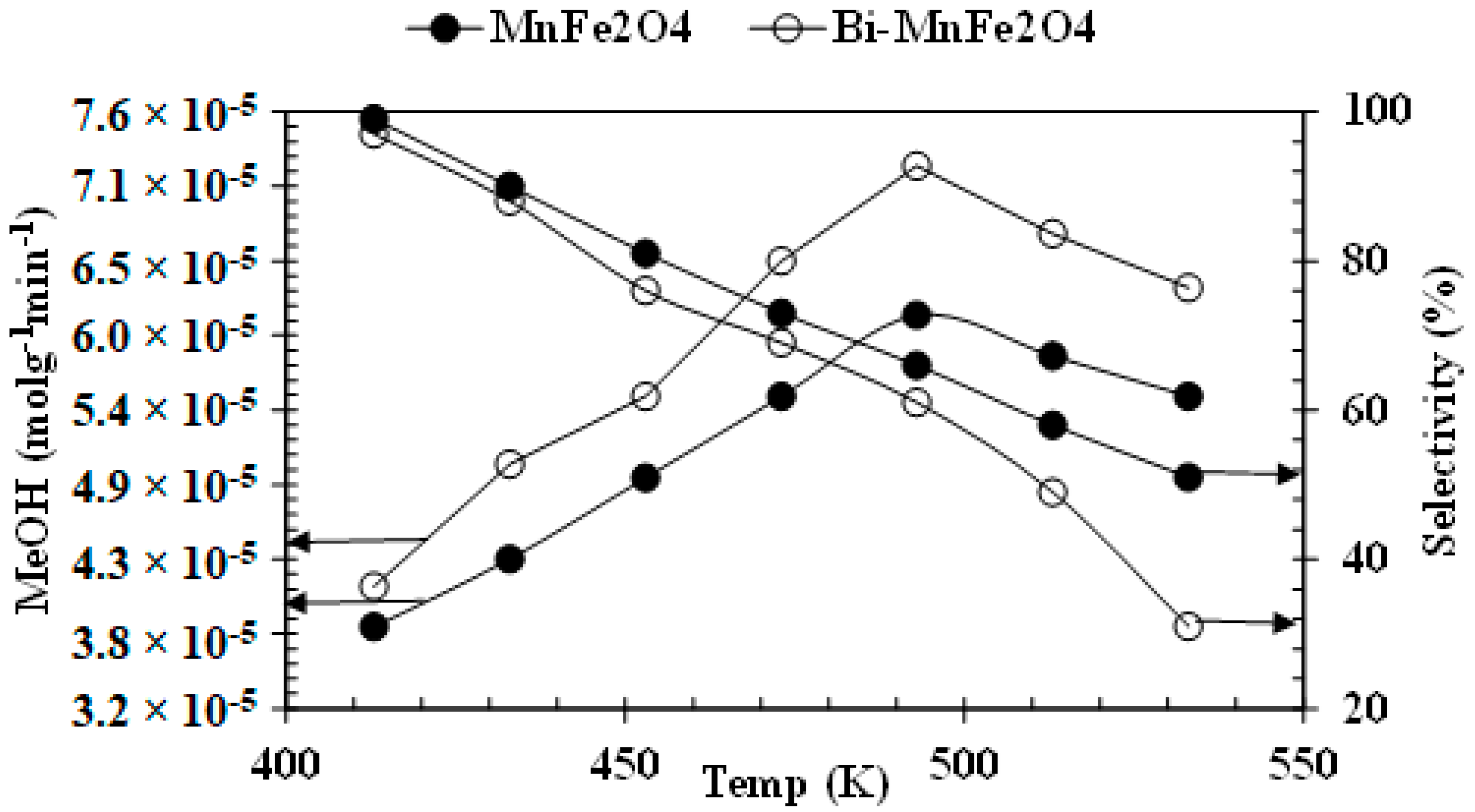
3.3. Catalytic Activity

In the recent study hydrogenation of carbon dioxide to VPs over magnetic nanoparticles was carried out in FPFBR under desired reaction parameters (pressure: 1 atm, temp: 413–563K, GHSV: 22,000 h−1, run time: 120 min, feed ratio 3/1: H2/CO2). The distribution of VPs was dependent on temperature, pressure, feed ratio of H2/CO2 and gas hourly space velocity (GHSV) [31,32]. Toyir et al. [33] obtained different VPs (CO, C2H6, C2H4O2, CH4 and CH3OH) with Cu-Ga/ZnO catalyst under reaction parameters (0.5 g), (3/1: H2/CO2), (543 K), (19.7 atm) and (150 mL/min). Here, we detected different VPs in the model reaction as given in the Table 2. However, further study focused only on the optimization of parameters for methanol synthesis from direct hydrogenation of carbon dioxide.
Reaction parameters for efficient catalytic activity and selectivity of the catalysts were comprehensively studied. Hasliza et al. [35] have reported an optimum selectivity of methanol formation (70%) per hour from direct CO2 hydrogenation over Pd/ZnO catalysts at 523 K and 20 bar in a fixed-bed flow reactor. Similarly, in the current study, the effect of reaction duration on the production rate of methanol was explored under the same set of reaction conditions. It was found that the production rate of MeOHattained steady state at 90 min and after that the rate became flattened as shown in Figure 3. Steady state of desired product (MeOH) among VPs was obtained after 90 min, so this was used as the optimal time for collection of further data. While selectivity to methanol decreases up to 60%, which is due the appearance of other products like C2H4O2 and H3COCH3, a very small amount of carbon monoxide was detected at TCD at our temperature zone.
Generally, increase in catalyst loading increases the rate of MeOH production [32]. The effect of catalyst loading was studied for the hydrogenation of CO2 to MeOH using 0.75 mol/h flow of H2 and 0.25 mol/h flow of CO2 at 493 K and data was collected after 90 min (for each individual study) under atmospheric pressure, as shown in Figure S3. The rate of MeOH production increased with the increase of catalyst loading up to some extent. The maximum product was observed at a dose of 2 g per reactor chamber (0.11 g per finger projected fixed-bed). Therefore, 2 g/chamber of catalyst was utilized for all experiments otherwise specified. The justification for this loading limit is that the finger-projected fixed beds are covered by the catalyst with a maximum quantity of 2 g/chamber and best ratio of reactant molecule to catalyst particles. It was found that the doped nanoparticle (Bi-MnFe2O4) shows better catalytic properties and selectivity for the reaction throughout the study as shown in Figure S4. The maximum selectivity of MeOH from CO2 under atmospheric pressure and 3/1 feed ratio of H2/CO2 was reported at low temperature hydrogenation. Ramirez et al. [32] reported the effect of temperature on selectivity for MeOH production at atmospheric pressure. They noticed decrease in selectivity up to elevated temperature, because high temperature favors the production of some other compounds during CO2 hydrogenation [14]. The reaction of CO2 hydrogenation for the purpose of MeOH production is usually favorable at lower temperatures because the product appears with a negative enthalpy (ΔH = −94.4 kJ.mol−1). In this study, the temperature was gradually increased in equal intervals from 413 to 563 K, MeOH formation first increased with the increase in temperature and then showed a gradual decline due to the appearance of C2H4O2, H3COCH3 and CO, as shown in Figure 4.
It has been confirmed that MNPs can be used as effective catalysts for CO2 conversion to MeOH. Dependence of rate of reaction on temperature was calculated from Arrhenius equation. The apparent activation energy (Ea) was calculated as 115.2 kJ mol−1 and 100 kJ mol−1 for MnFe2O4 and Bi-MnFe2O4 respectively. Yang et al. [36] have reported an amount of 133 kJ mol-1 activation energy (Ea) for the catalytic hydrogenation of CO2 to MeOH at low temperature (403–453 K) and a total pressure of 6 bar over copper catalysts which is in good agreement with recent study as shown in Table S1, entry 1. MnFe2O4 has shown efficient catalytic activity in a number of gas phase chemical reactions [37]. Subsequent studies have shown that doping of various other metals over MnFe2O4 considerably increases the catalytic properties of such nanoparticles [38], due to their synergistic effect. In this study we found that doping of Bi in smaller concentration increased the catalytic properties of nano MnFe2O4. The interaction of metal and metal oxide proves phase modification for the good catalytic activity of Bi-MnFe2O4. Throughout the study Bi-MnFe2O4 shown better catalytic performance but with reduction in magnetic properties. Figure S4 shows comparison of the catalytic activity of MnFe2O4 and Bi-MnFe2O4 at different time intervals and temperature values.

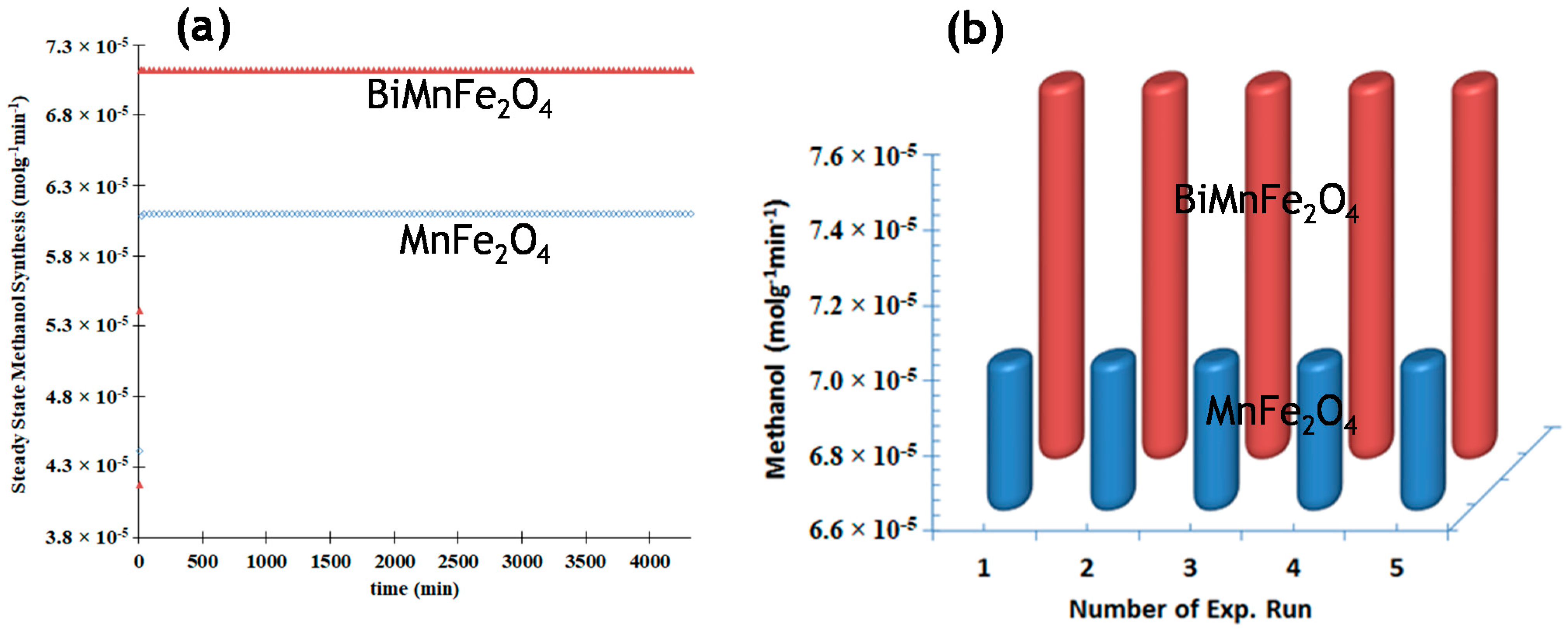
3.4. Stability of Catalysts

As discussed earlier, MnFe2O4 can be reused several times for the model reaction due to its hydrophobic nature. A series of experiments was carried out under the optimal set of parameters in order to check the stability and recyclability of the catalysts. Both catalysts showed stable catalytic activity after being used for extended time (72 h) and recycling for five consecutive cycles. MNPs were recovered by removing the external magnets from the grooves of the fingers after the completion of reaction. Doped MNPs showed their enhanced catalytic activity under the described set of parameters. Figure 5 shows the life span of MnFe2O4 and Bi-MnFe2O4 for CO2 conversion to MeOH.

3.5. Comparative Study of Different Reactors

Several types of reactors have been used for catalytic hydrogenation of CO2 to MeOH so far. The higher efficiency of recently used FPFBR shows that fixed-bed reactors can be modified in many ways for the utilization of CO2 to various valuable organic products. The greater advantage of recently used FPFBR over the conventional fixed-bed reactors is due to the fact that the gas molecules pass over 18 fixed beds in a single reactor chamber (90 beds in five chambers) in comparison to a single or few beds of the conventional fixed-bed reactors. This means that the reactant molecules have greater chance to collide with catalyst particles over 18 beds/chamber and hence maximum reaction rate is expected. Moreover, mild operational conditions like atmospheric pressure and low temperature dominate the reactor over the conventionally used fixed-bed reactors. Marina and coworkers [Table S1, entry 4] have used a heterogeneous model of fixed-bed reactor in which they performed direct catalytic hydrogenation of CO2 to MeOH over Cu/ZnO/Al2O3 catalyst under pressure up to 100 bar and temperature of 473–533 K. They achieved maximum yield with an activation energy value of 44 kJ mol−1. Similarly, fixed-bed reactors have been used for the catalytic hydrogenation of CO2 to MeOH over Cu/ZnO catalyst at 525–575 K and 5 bar. They observed maximum yield at activation energy 116.7 kJ mol−1 is presented in Table S1, entry 6. Elsewhere a fixed-bed reactor was used for CO2 over Pd-CuZnO at 503–543 K and 45 bar. The observed activation energy value was 31 kJ mol−1 in their study, as presented in Table S1, entry 10. The reported literature tabulated in the Table S1 is a stimulus for modification in fixed-bed reactor for magnetic nanoparticles with excellent performance trials.

4. Conclusions

The calculated efficiency of the reactor (74%) shows the usefulness of the self-architecture reactor (finger-projected fixed-bed reactor) for the catalytic hydrogenation of carbon dioxide (CO2) to VPs using magnetic nanoparticles (MnFe2O4/Bi-MnFe2O4) as catalysts. The fixed-bed reactor was modified for magnetic nanoparticles with multifocused points, such as (i) availability of many reaction cores, (ii) enhancing collision probability of reactant/catalysts molecules, (iii) easy handling and mild conditions of operation, (iv) easy recovery of catalysts, and (v) performance trial efficiency. Furthermore, high activity and selectivity were obtained at 493 K, when MnFe2O4 was calcined at 513 K (0.5 °C/min) for 4 h and reduced at 553 K for 2 h, while in the case of Bi-MnFe2O4, calcination was performed at 753 K (0.5 °C/min) for 6 h and reduced at 553 K for 2 h. Further reduction modified mix phases of metal/metal oxide system which indeed enhanced the catalytic activity. Bismuth doping no doubt increases the catalytic activity but decreases the magnetic properties of the MnFe2O4. The magnetic properties were retrieved by high temperature treatment for extended time (6 h). In short, a finger-projected fixed-bed reactor in combination with magnetic nanoparticles will be an excellent alternative for industrial conversion of CO2 to MeOH to boost the world economy and mitigate greenhouse gases.

Supplementary Materials

The following are available online at https://www.mdpi.com/article/10.3390/catal11050592/s1, Figure S1: Schematic diagram of reaction setup and finger-projected fixed-bed reactor (FPFBR) used for hydrogenation of CO2 to methanol; Figure S2: a, XRD pattern of MnFe2O4 (pattern a), Bi-MnFe2O4 (pattern b), b, FTIR spectra of MnFe2O4 (curve a), Bi-MnFe2O4 (curve b); Figure S3: Effect of catalyst loading per chamber on the rate of CO2 hydrogenation to MeOH; Figure S4: Comparison of the catalytic activity of MnFe2O4 and Bi-MnFe2O4 for CO2 conversion to MeOH; Table S1: Different types of reactors used for hydrogenation of CO2 to MeOH under various reaction conditions.

Author Contributions

Investigation, M.B.; conceptualization and methodology, R.U., M.S. and K.S.; writing—original draft preparation M.S. and S.S.; writing—review and editing, I.K., M.A.Z., Z.I. (Zaffar Iqbal), I.U., Z.I. (Zahoor Iqbal) and S.A.; All authors have read and agreed to the published version of the manuscript.

Funding

This research was funded by Higher Education Commission of Pakistan (20-1604/R&D/HEC/092198 & 20-189/NRPU/R&D/HEC116806) and Pakistan Science Foundation (PSF/Res/F-UM/Chem (434).

Data Availability Statement

www.uom.edu.pk, accessed on 2 May 2021.

Conflicts of Interest

The authors declare no conflict of interest.

References

  1. Aresta, M.; DiBenedetto, A. Utilisation of CO2 as a chemical feedstock: Opportunities and challenges. Dalton Trans. 2007, 28, 2975–2992. [Google Scholar] [CrossRef] [PubMed]
  2. Zahedi, G.; Elkamel, A.; Lohi§, A. Dynamic Optimization Strategies of a Heterogeneous Reactor for CO2 Conversion to Methanol. Energy Fuels 2007, 21, 2977–2983. [Google Scholar] [CrossRef]
  3. Ateka, A.; Pérez-Uriarte, P.; Gamero, M.; Ereña, J.; Aguayo, A.T.; Bilbao, J. Aguayo and J. Bilbao A comparative thermodynamic study on the CO2 con-version in the synthesis of methanol and of DME. Energy 2017, 120, 796–804. [Google Scholar] [CrossRef]
  4. von der Assen, N.; Müller, L.J.; Steingrube, A.; Voll, P.; Bardow, A. Selecting CO2 sources for CO2 utilization by environmental-merit-order curves. Environ. Sci. Technol. 2016, 50, 1093–1101. [Google Scholar] [CrossRef]
  5. Ahmad, K.; Upadhyayula, S. Greenhouse gas CO2 hydrogenation to fuels: A thermodynamic analysis. Environ. Prog. Sustain. Energy 2019, 38, 98–111. [Google Scholar] [CrossRef] [Green Version]
  6. Kumar, P.; With, P.; Srivastava, V.C.; Gläser, R.; Mishra, I.M. Conversion of carbon dioxide along with methanol to dimethyl car-bonate over ceria catalyst. J. Environ. Chem. Eng. 2015, 3, 2943–2947. [Google Scholar] [CrossRef]
  7. Wisaijorn, W.; Poo-Arporn, Y.; Marin, P.; Ordóňez, S.; Assabumrungrat, S.; Praserthdam, P.; Saebea, D.; Soisuwan, S. Reduction of carbon dioxide via catalytic hydrogenation over copper-based catalysts modified by oyster shell-derived calcium oxide. J. Environ. Chem. Eng. 2017, 5, 3115–3121. [Google Scholar] [CrossRef]
  8. Akhter, P.; Farkhondehfal, M.A.; Hernández, S.; Hussain, M.; Fina, A.; Saracco, G.; Khan, A.U.; Russo, N. Environmental issues regarding CO2 and recent strategies for alternative fuels through photocatalytic reduction with titania-based materials. J. Environ. Chem. Eng. 2016, 4, 3934–3953. [Google Scholar] [CrossRef]
  9. Ranjbar, A.; Irankhah, A.; Aghamiri, S.F. Reverse water gas shift reaction and CO2 mitigation: Nanocrystalline MgO as a support for nickel based catalysts. J. Environ. Chem. Eng. 2018, 6, 4945–4952. [Google Scholar] [CrossRef]
  10. Samimi, F.; Hamedi, N.; Rahimpour, M.R. Green methanol production process from indirect CO2 conversion: RWGS reactor versus RWGS membrane reactor. J. Environ. Chem. Eng. 2019, 7, 102813. [Google Scholar] [CrossRef]
  11. Rahimpour, M. A two-stage catalyst bed concept for conversion of carbon dioxide into methanol. Fuel Process. Technol. 2008, 89, 556–566. [Google Scholar] [CrossRef]
  12. Liu, X.-M.; Lu, G.Q.; Yan, Z.-F.; Beltramini, J. Recent Advances in Catalysts for Methanol Synthesis via Hydrogenation of CO and CO2. Ind. Eng. Chem. Res. 2003, 42, 6518–6530. [Google Scholar] [CrossRef]
  13. Din, I.U.; Usman, M.; Khan, S.; Helal, A.; Alotaibi, M.A.; Alharthi, A.I.; Centi, G. Prospects for a green methanol thermo-catalytic process from CO2 by using MOFs based materials: A mini-review. J. CO2 Util. 2021, 43, 101361. [Google Scholar] [CrossRef]
  14. Bukhtiyarova, M.; Lunkenbein, T.; Kähler, K.; Schlögl, R. Methanol Synthesis from Industrial CO2 Sources: A Contribution to Chemical Energy Conversion. Catal. Lett. 2017, 147, 416–427. [Google Scholar] [CrossRef] [Green Version]
  15. Tursunov, O.; Kustov, L.; Kustov, A. A Brief Review of Carbon Dioxide Hydrogenation to Methanol Over Copper and Iron Based Catalysts. Oil & Gas Sci. Technol. Rev. d’IFP Energ. Nouv. 2017, 72, 30. [Google Scholar] [CrossRef] [Green Version]
  16. Bansode, A.; Tidona, B.; von Rohr, P.R.; Urakawa, A. Impact of K and Ba promoters on CO2 hydrogenation over Cu/Al2O3 catalysts at high pressure. Catal. Sci. Technol. 2013, 3, 767–778. [Google Scholar] [CrossRef]
  17. Arab, S.; Commenge, J.-M.; Portha, J.-F.; Falk, L. Methanol synthesis from CO2 and H2 in multi-tubular fixed-bed reactor and multi-tubular reactor filled with monoliths. Chem. Eng. Res. Des. 2014, 92, 2598–2608. [Google Scholar] [CrossRef]
  18. Zhang, J.; Wang, H.; Dalai, A.K. Effects of metal content on activity and stability of Ni-Co bimetallic catalysts for CO2 reforming of CH4. Appl. Catal. A Gen. 2008, 339, 121–129. [Google Scholar] [CrossRef]
  19. Sugawa, S.; Sayama, K.; Okabe, K.; Arakawa, H. Methanol synthesis from CO2 and H2 over silver catalyst. Energy Convers. Manag. 1995, 36, 665–668. [Google Scholar] [CrossRef]
  20. Hong, Z.S.; Cao, Y.; Deng, J.F.; Fan, K.N. CO2 hydrogenation to methanol over Cu/ZnO/Al2O3 catalysts prepared by a novel gel-network-coprecipitation method. Catal. Lett. 2002, 82, 37–44. [Google Scholar] [CrossRef]
  21. Chary, K.V.; Kumar, C.P.; Rao, P.V.R.; Rao, V.V. Dispersion and reactivity of V2O5 catalysts supported on Al2O3–ZrO2. Catal. Commun. 2004, 5, 479–484. [Google Scholar] [CrossRef]
  22. Dominguez, J.; Hernandez, J.; Sandoval, G. Surface and catalytic properties of Al2O3–ZrO2 solid solutions prepared by sol–gel methods. Appl. Catal. A Gen. 2000, 197, 119–130. [Google Scholar] [CrossRef]
  23. Yoon, T.-J.; Lee, W.; Oh, Y.-S.; Lee, J.-K. Magnetic nanoparticles as a catalyst vehicle for simple and easy recycling. New J. Chem. 2003, 27, 227–229. [Google Scholar] [CrossRef]
  24. Venkataraju, C.; Satishkumar, G.; Sivakumar, K. Effect of bismuth on the properties of Mn ferrite nanoparticles prepared by co-precipitation method. J. Mater. Sci. Mater. Electron. 2012, 23, 1163–1168. [Google Scholar] [CrossRef]
  25. Prabhakaran, T.; Mangalaraja, R.; Denardin, J.C.; Jiménez, J.A. The effect of calcination temperature on the structural and magnetic properties of co-precipitated CoFe2O4 nanoparticles. J. Alloys Compd. 2017, 716, 171–183. [Google Scholar] [CrossRef]
  26. Zhang, Y.; Fei, J.; Yu, Y.; Zheng, X. Study of CO2 Hydrogenation to Methanol over Cu-V/γ-Al2O3 Catalyst. J. Nat. Gas Chem. 2007, 16, 12–15. [Google Scholar] [CrossRef]
  27. Zhou, X.; Su, T.; Jiang, Y.; Qin, Z.; Ji, H.; Guo, Z. CuO-Fe2O3-CeO2/HZSM-5 bifunctional catalyst hydrogenated CO2 for enhanced dimethyl ether synthesis. Chem. Eng. Sci. 2016, 153, 10–20. [Google Scholar] [CrossRef]
  28. Han, A.; Liao, J.; Ye, M.; Li, Y.; Peng, X. Preparation of nano-MnFe2O4 and its catalytic performance of thermal decomposition of ammonium perchlorate. Chin. J. Chem. Eng. 2011, 19, 1047–1051. [Google Scholar] [CrossRef]
  29. Jacintha, A.M.; Umapathy, V.; Neeraja, P.; Rajkumar, S.R.J. Synthesis and comparative studies of MnFe2O4 nanoparticles with different natural polymers by sol–gel method: Structural, morphological, optical, magnetic, catalytic and biological activities. J. Nanostruct. Chem. 2017, 7, 375–387. [Google Scholar] [CrossRef] [Green Version]
  30. Abraham, S.D.; David, S.T.; Bennie, R.B.; Joel, C.; Kumar, D.S. Eco-friendly and green synthesis of BiVO4 nanoparticle using microwave irradiation as photocatalayst for the degradation of Alizarin Red S. J. Mol. Struct. 2016, 1113, 174–181. [Google Scholar] [CrossRef]
  31. Yang, H.; Zhang, C.; Gao, P.; Wang, H.; Li, X.; Zhong, L.; Wei, W.; Sun, Y. A review of the catalytic hydrogenation of carbon dioxide into value-added hydrocarbons. Catal. Sci. Technol. 2017, 7, 4580–4598. [Google Scholar] [CrossRef]
  32. Díez-Ramírez, J.; Dorado, F.; De La Osa, A.R.; Valverde, J.L.; Sánchez, P. Hydrogenation of CO2 to Methanol at Atmospheric Pressure over Cu/ZnO Catalysts: Influence of the Calcination, Reduction, and Metal Loading. Ind. Eng. Chem. Res. 2017, 56, 1979–1987. [Google Scholar] [CrossRef]
  33. Toyir, J.; De La Piscina, P.R.; Llorca, J.; Fierro, J.-L.G.; Homs, N. Methanol synthesis from CO2 and H2 over gallium promoted copper-based supported catalysts. Effect of hydrocarbon impurities in the CO2/H2 source. Phys. Chem. Chem. Phys. 2001, 3, 4837–4842. [Google Scholar] [CrossRef]
  34. Iwasa, N.; Masuda, S.; Ogawa, N.; Takezawa, N. Steam reforming of methanol over Pd/ZnO: Effect of the formation of PdZn alloys upon the reaction. Appl. Catal. A Gen. 1995, 125, 145–157. [Google Scholar] [CrossRef]
  35. Wang, Y.; Kattel, S.; Gao, W.; Li, K.; Liu, P.; Chen, J.G.; Wang, H. Exploring the ternary interactions in Cu–ZnO–ZrO2 catalysts for efficient CO2 hydrogenation to methanol. Nat. Commun. 2019, 10, 1166. [Google Scholar] [CrossRef] [PubMed]
  36. Yang, Y.; Mims, C.A.; Mei, D.; Peden, C.H.; Campbell, C.T. Mechanistic studies of methanol synthesis over Cu from CO/CO2/H2/H2O mixtures: The source of C in methanol and the role of water. J. Catal. 2013, 298, 10–17. [Google Scholar] [CrossRef]
  37. Yang, Y.; Liu, J.; Zhang, B.; Liu, F. Density functional theory study on the heterogeneous reaction between HgO and HCl over spinel-type MnFe2O4. Chem. Eng. J. 2017, 308, 897–903. [Google Scholar] [CrossRef]
  38. Wang, Z.; Ma, H.; Zhang, C.; Feng, J.; Pu, S.; Ren, Y.; Wang, Y. Enhanced catalytic ozonation treatment of dibutyl phthalate enabled by porous magnetic Ag-doped ferrospinel MnFe2O4 materials: Performance and mechanism. Chem. Eng. J. 2018, 354, 42–52. [Google Scholar] [CrossRef]
Figure 1. Experimental set-up of methanol synthesis.
Catalysts 11 00592 g001
Figure 2. (a,b): SEM images of MnFe2O4 at different magnifications; (c,d): EDX spectra and elemental analysis of MnFe2O4; (e,f): SEM images of Bi doped MnFe2O4 at different magnifications; (g,h): EDX spectra and elemental analysis of Bi-MnFe2O4.
Catalysts 11 00592 g002
Figure 3. Time profile study of CO2 conversion to MeOH by MnFe2O4 and Bi-MnFe2O4 catalysts. Reaction conditions: pressure: 1 bar, temp: 493 K, GHSV: 22,000 h−1, feed ratio 3/1: H2/CO2.
Catalysts 11 00592 g003
Figure 4. Effect of temperature on the rate of MeOH production and selectivity. Reaction conditions: pressure: 1 bar, GHSV: 22,000 h−1, data collected after 90 min, feed ratio: 3/1 H2/CO2.
Catalysts 11 00592 g004
Figure 5. Life span/reusability of MnFe2O4 and Bi-MnFe2O4 for CO2 conversion to MeOH. Reaction conditions: pressure: 1 bar, temp: 493 K, (a) extended time; 4320 min, GHSV: 22,000 h−1, feed ratio: 3/1 H2/CO2, (b) no. of runs: 5 (data collected after 90 min).
Catalysts 11 00592 g005
Table 1. Morphology, particle size and surface area of catalysts.
EntryCatalystsMorphologySize (nm) *BET (m2/g)
1MnFe2O4Spinel64.132
2BiMnFe2O4Hexagonal/spinel79.329
* Particle size calculated from XRD has good agreement with particle size calculated by AGI method.
Table 2. Comparative study for valuable organic products under different reaction parameters.
* VPsConditions: 1 Cat, 2 FR, 3 T, 4 P, 5 GFR a Conv/b SelRef
H3COCH3
CH3OH
CuO-ZnO-Al2O3-ZrO2+HZSM-5 (1), 3/1, 473, 49.3, 10015.8/74
5.4/25
[31]
CO
CH4
CH3OH
20CuZnO-350-200 (0.8), 9/1, 498, 1,10014/77.3
14/17
14/4.4
[32]
CO
CH3OH
5%Pd/ZnO (0.5), 3/1, 523, 19.7, 3010.7/39
10.7/60
[34]
CH3OHCu/ZnO/Al2O3 (1), 7/2, 473, 29.6, 1504/68[14]
CO
H3COCH3
C2H4O2
CH3OH
Cu/Al2O3 (0.17), 3.8/1, 553, 355, 0.011
Cu/Al2O3 (0.17), 3.8/1, 553, 98.7, 0.011
Cu/Al2O3 (0.17), 3.8/1, 443, 355.2, 0.011
Cu/Al2O3 (0.17), 3.8/1, 473, 355.2, 0.011
29/91.7
21/8.5
3/3.1
8/48
[16]
CH3OH
C2H4O2
H3COCH3
Bi-MnFe2O4, (2/chamber), 3/1, 493, 1, 40
Bi-MnFe2O4, (2/chamber), 3/1, 563, 1, 40
Bi-MnFe2O4, (2/chamber), 3/1, 543, 1, 40
22/61
6/33
4/19
Present work
* Valuable organic products detected in the hydrogenation of CO2 under different reaction parameters: 1 catalyst (g), 2 feed ratio (H2/CO2), 3 temperature (K), 4 pressure (atm), 5 gas flow rate (mL/min), a conversion (%), b selectivity (%).
Publisher’s Note: MDPI stays neutral with regard to jurisdictional claims in published maps and institutional affiliations.

