
Performance of Sulfide-Driven Fuel Cell Aerated by Venturi Tube Ejector


Institute of Chemical Engineering, Bulgarian Academy of Sciences, 1113 Sofia, Bulgaria
*
Author to whom correspondence should be addressed.
Catalysts 2021, 11(6), 694; https://doi.org/10.3390/catal11060694
Submission received: 5 May 2021
/
Revised: 27 May 2021
/
Accepted: 28 May 2021
/
Published: 30 May 2021
(This article belongs to the Special Issue Design of Electrocatalysts for Green Hydrogen Production from Hydrogen Sulfide and Seawater)
Abstract
:Hydrogen sulfide is frequently met in natural waters, like mineral springs, but mostly it is found in marine water with low renewal rate. The Black Sea has extremely high hydrogen sulfide content. It can be utilized in different ways, but the most promising one is direct conversion into electricity. This result can be attained by a sulfide-driven fuel cell (SDFC), converting sulfide to sulfate thus releasing electric energy up to 24 GJ/t. One of the most important problems is the mass transfer limitation on oxygen transfer in the cathode space of the fuel cell. This problem can be solved using a gas diffusion electrode or highly efficient saturation by oxygen in an ejector of the Venturi tube type. This work presents experimental data in laboratory-scale SDFC for sulfide conversion into sulfate, sulfite and polysulfide releasing different amounts of electric energy. Two types of aeration are tested: direct air blow and Venturi-tube ejector. Besides pure graphite, two catalysts, i.e., cobalt spinel and zirconia-doped graphite were tested as anodes. Experiments were carried out at initial sulfide concentrations from 50 to 300 mg/L. Sulfate, sulfite and thiosulfate ions were detected in the outlet solutions from the fuel cell. The electrochemical results show good agreement with the chemical analyses. Most of the results show attained high efficiencies of the fuel cell, i.e., up to 80%. The practical applications of this method can be extended for other purposes, like treatment of polluted water together with utilization as energy.
1. Introduction
Hydrogen sulfide is frequently found in nature. Its origin varies from natural mineral water springs, through natural water ponds to industrial waste flows, e.g., oil desulfurization processes. In all cases its presence in nature is not desirable and there are many efforts to remove it both from natural ponds and industrial outflows.
There are efforts to remove hydrogen sulfide in a fuel cell process in liquid phase where electricity is generated because of reduction of sulfide to elemental sulfur [1,2]. However, the latter is harmful for the fuel cell performance because of blocking the anode and because it is poisonous for the catalysts used in the fuel cell [3]. Different oxidizer except oxygen have been tested—cyanoferrate [4], bichromate [5] ferric ions [6]. However, addition of chemicals is not admissible to the sensitive environment like the water of the Black Sea. There are also data for sulfide removal in microbial fuel cells [7]. Our efforts are to design a sulfide-driven fuel cell (SDFC) operating in aqueous medium and based on the oxidation of sulfide to sulfate-generating electromotive driving force [8,9].
The principle of SDFC is shown in Figure 1. The electrode reactions are:
for proton-mediated process and,
and,
when the redox process is accompanied by transfer of hydroxylic anion through the membrane. In both cases the net reaction is:
Anode: S2− + 4H2O − 8e− = SO42− + 8H+, Eo = 0.149 V
Cathode: 2O2 + 8H+ + 8e− = 4H2O, Eo =1.229 V
Anode:S2− + 6OH− − 6e− = SO2− + 3H2O; Eo = −0.61 V
SO32−+2OH− − 2e− = SO42− + H2O, Eo= −0.90 V; Total: Eo = −0.68 V
Cathode: 2O2 + 4H2O + 8e− = 8OH−; Eo = 0.401 V
S2− + 2O2 = SO42−
The enthalpy of the latter reaction (4) is −774 kJ mole−1. For a reference, the enthalpy of methane combustion is −890.8 kJ mole−1 and for hydrogen combustion −568.8 kJ mole−1. The theoretical electromotive force of such a fuel cell element is 1.08 V. The final product is sulfate ions in moderate concentration being compatible with the natural sea water.
Interest in this approach has been provoked by the enormous amount of hydrogen sulfide accumulated in some natural bodies of water, the Black Sea in particular. The total amount is estimated to 4.7 Gtons [10,11]. The annual increase is estimated to 20 mln tons and its processing could produce up to 100 TWh electrical energy. It corresponds to a continuously operating facility of 12,000 MW.
For a reference, the annual consumption of electrical energy in Bulgaria for the year 2015 was 37.8 TWh.
This attractive approach is restricted by the low concentration of sulfide in the Black Sea water: it reaches 22 g m−3 at depths of 2200 m. The practical applications of such fuel cells are also impeded by the high corrosion activity of sulfide. This requires the use of non-corrosive plastic materials and electrodes resistant to sulfide corrosion. In the case of working in natural conditions, no other supporting electrolyte except marine water is acceptable. Only oxygen as electron acceptor in the cathode space is admissible.
This approach could be applied to oil desulfurization by absorption of gaseous hydrogen sulfide in alkaline solution and passing the latter through a sulfide-driven fuel cell. Hence, the benefits of this approach is double: processing the waste streams and energy production.
A significant property of sulfur compounds is the broad variety of redox reactions that may happen in aqueous media. Some of them are shown in Table 1, an excerpt from [12]. It is visible that different number of electrons are exchanged and different standard redox potentials and electromotive forces will be generated. That is why the most preferred target reactions, i.e., sulfide-to-sulfate oxidation with eight exchanged electrons must be achieved.
The idea for the application of a sulfide-driven fuel cell is not new [5,6,7,8,9,13,14,15,16] but it is of big importance for a simultaneous solution of environmental problems in the Black Sea and as a green approach for carbon free energy.
The limitations on oxygen mass transfer rate in the cathode space and the low oxygen concentration in marine water impose big problems on the fuel cell performance. It is well known that the Venturi tube ejectors enable high mass transfer rates and good water saturation with gases at very low energy demand [17]. It can be used for feeding the cathode space saturated by oxygen solution. This study presents experimental results on the performance of a sulfide-driven fuel cell supplied with oxygen after aeration by a Venturi tube ejector of the solution feeding the cathode space. The results are compared to those obtained through simple bubble aeration.
There are own data on the effect of cobalt spinel and zirconia tested as catalysts for the sulfide redox processes.
2. Results and Discussion
2.1. Cycle Voltammetric Studies
Some of the results obtained with and without the catalyst are shown in Table 2. A comparison between the data for the voltammetric curves obtained by Co-spinel catalyst and by graphite electrodes without catalyst is shown in Figure 2 and Table 2. The plots according to the Butler–Volmer equation, Equation (S1), show different exchange currents and anodic reactions as well as anodic transfer coefficients for the two considered cases, see Table 2 and Table 3. The hysteresis of the data obtained without catalysts is almost negligible, i.e., reversible processes take place on the anode. The anode potentials when no electric current flows are 0.221 and 0.236 V/S.H.E. for the forward and backward moves, respectively.
When carbon felt without catalyst was used as electrode, the oxidation of sulfide to higher valence, i.e., S4+ (as sulfite) was detected.
When cobalt spinel was applied, the anode processes were clearly irreversible with a large hysteresis. In this case the equilibrium anode potentials were −0.092 and 0.013 V/S.H.E. The dominating anode processes were polysulfide formation as proven qualitatively.
Better results were obtained when graphite without catalysts was used for both electrodes. In these cases the transfer coefficients were somewhat higher than those for anode doped with Co-spinel. Generally, the observed transfer coefficients are moderate, lower than the best values expected around 0.5. A Butler-Volmer plot for batch experiments with carbon felt as anode with and without cobalt spinel at 23 °C is shown in Figure S1.
It must be noted that sulfide anions are aggressive toward metal cations, as cobalt is. That is why there is a threat of the cobalt spinel-type catalyst being gradually destroyed and removed after a few applications.
2.2. Polarization Curves
Polarization curves for three different sulfide concentrations, obtained in a fuel cell using plane graphite electrodes with direct aeration and without catalysts are shown in Figure 3 and Figure 4. One can see that there is an optimal sulfide concentration, i.e., around 240 mg dm−3. The possible explanation is that above certain concentration values undesired reactions take place in the bulk liquid competing the electrochemical processes on the anode. For the concentration range from 55 to 265 mg dm−3 the estimated overpotential at low current densities was less than 5 mV, i.e., the barrier losses were negligible.
The polarization curve for a two fuel cell stack is shown in Figure S2. The open circuit potential (OCP) for the stack is 1.28 V, i.e., it is 59% of the theoretical one. The OCPs for the two separate fuel cells in the stack are 0.533 (49% efficiency) and 0.753 V (70% efficiency).
Polarization curves for two different sulfide concentrations obtained in a fuel cell with plane graphite electrodes and preliminary saturated water with oxygen by Venturi-type ejector for continuous and batch mode of operation are shown in Figure 5a,b. The ohmic resistance was around 1.6 Ω for a single fuel cell with practically no overpotential losses. The cell efficiency (as open circuit potential) at continuous feed was 61% of the theoretical value.
The results for the polarization curves in Figure 3, Figure 4 and Figure 5, Figure S2 show that there are negligible voltage losses due to overpotential at low current densities with relatively high fuel cell efficiencies, reaching 70% of the theoretical value. However, for practical purposes it is necessary to reach higher current and power densities. This can be achieved by reduction in the ohmic resistance in the anode compartment and of the membrane separator.
An important issue is the limitation to oxygen mass transfer rate, due to the low saturation concentration and the saturation rate in the cathode compartment.
2.3. Results on Fuel Cell Discharge at Different Aeration Modes
2.3.1. Direct Aeration
First, results on fuel cell discharge at direct aeration in the cathode space will be considered. The fuel cell discharge was carried out both in batch and continuous modes. In all cases the ohmic resistance of the load was equal or close to the internal fuel cell resistance. Results for a two cell stack with direct aeration and continuous mode are shown in Figure 6. The open circuit potential in the beginning was about 90% of the theoretical value. Besides sulfide, thiosulfate was detected qualitatively in the inlet solution. In the outlet solution only sulfate was detected.
Calculations by the current Coulombic efficiency by Equation (S2) show that at direct aeration only 26% of the sulfide was converted into sulfate by the electrochemical process. The rest of the sulfide was depleted by chemical oxidation in the bulk. The process of sulfide to sulfite oxidation in a bulk is an expected parasite reaction. If it is correct, the anode reaction will be sulfite to sulfate oxidation involving two exchanged electrons. In this case corresponding current efficiency will give over 100% yield of sulfate, which is not realistic.
2.3.2. Aeration by Venturi Tube Ejector
There is comparison of the sulfide conversion rates calculated by the Faraday’s law to the analytically determined values for two types of aeration, shown in Figure 7. The advantage of the aeration by ejector as aeration tool is obvious. As one can see, the most probable anode reactions are those exchanging six or eight electrons, i.e., leading to oxidation of sulfide to sulfite and sulfate.
The efficiencies of the anode reactions when six or eight electrons are exchanged are reasonable and below 100% of the analytically determined ones. The values, calculated for two and four exchanged electrons give values much higher than 100 of the analytically determined values.
A result for fuel cell discharge with preliminary air saturation by Venturi-type ejector is shown in Figure S3. The open circuit potential at the beginning is about 60% of the theoretical thermodynamic value. The calculations by the Coulombic current efficiency, cf. Equation (S2), show that the electrochemical anode process of sulfide to sulfate oxidation was almost complete. The measured sulfide depletion rate corresponds to a conversion rate of 11.9 mg/h for sulfide to sulfate conversion, whereas that determined by chemical analysis was 12.8 mg/h. Hence, yield of 93% was achieved. The positive effect of the intensive preliminary aeration is evident. That is why one may draw a conclusion that the cathode process of oxygen reduction and the corresponding transfer of protons (or hydroxylic anions) through the separation membrane are rate-determining. Another possibility to enhance the overall process is to use pure oxygen or oxygen enriched air. However, it will be costly from a practical point of view.
The results obtained for the sulfide driven fuel cell efficiency at preliminary aeration by Venturi tube ejector are shown in Table S1. The calculations according the Faraday’s law, Equation (S2), involving a different number of exchanged electrons and compared to the determined ones are shown in Table S1. The number of exchanged electrons (2, 4, 6, 8) corresponds to different reactions in Table 1. Experiment No. 1 is carried out with zirconia-doped graphite as anode.
One can see that anode reactions (2, 10, 12) with the exchange of six and eight electrons seem more probable because the calculated sulfide depletion rates for lower numbers of exchanged electrons are higher than the analytically determined ones. There was no polysulfide detected in the outlet stream for these experiments. Therefore, one can conclude that in the considered cases more probable anode reactions for sulfide oxidation are oxidation to sulfite (reaction 2) and sulfate (12) or the consecutive oxidation of sulfide to sulfite and then to sulfate (consecutive reactions 1 and 2). The calculated current efficiencies for the runs shown in Table S1 vary from 20 % to 93% for reaction 12 and from 30% to 92% for reaction 2.
There are experiments where reactions involving exchange of two electrons also seem realistic compared to the analytical data, see experiments 4, 7, 8 (Table S1). However, no elemental sulfur nor polysulfide as products of the electrochemical reaction have been detected in the outlet stream. That is why, the oxidation of sulfite to sulfate is more probable in these cases. We expect that sulfite was obtained in a parasite reaction in the anodic compartment of the fuel cell after partial oxidation of sulfide to sulfite. Evidence for this explanation are the sulfite anions detected in the outlet stream together with sulfate. With this explanation we can accept the high sulfide depletion rates in the case of reaction 1, i.e., above 80%.
In some cases the reaction 8, i.e., sulfide oxidation to thiosulfate seems probable, cf. experiments 2–4, 7–9. However, thiosulfate were detected in the outlet stream for experiments 7 and 8 only. Therefore, one can conclude that the dominating electrochemical reactions in the considered cases are reactions 2, 12 and the consecutive oxidation to sulfide to sulfite and sulfate (reactions 1 and 2).
The experiment carried out with zirconia doped anode show reasonable results for the sulfide depletion rate cf. Figure 8 and run 1 in Table S1. For the case of sulfide to sulfate conversion (reaction 12) it is 70% of the analytically determined value and for the case of reaction 2 (sulfide to sulfite oxidation) it is 92%. However, questionable is the catalyst stability and the reproducibility of its properties in the aggressive sulfide media.
There are some problems to be solved before thinking of practical applications for the proposed fuel cell.
First, it is necessary to enhance the current and power densities ten times at least. This could be attained in different ways: selection of separator with high ionic conductivity; to test a fuel cell construction without membrane separator; to increase further the anode active area using graphite particles, carbon felt, etc. There are some data in the literature showing better current and power densities for such fuel cells, but with concentrated solutions of sodium hydroxide as supporting electrolyte [16]. It is inadmissible from an environmental point of view in our case. There are data in the literature for application of metal electrodes, stabilized as sulfide catalysts [12]. Higher current and power densities were attained −75 mA cm−2 and 23 mW cm−2 respectively. However, the resistibility of the catalysts in sulfide-rich media is questionable.
Second, to enhance the conversion efficiency of sulfide to sulfate conversion. This could be accomplished by improving fuel cell construction and coupling more cells in a consecutively operation assembly.
Third, to prevent the parasite auto-oxidation of sulfide to sulfite in the anode compartment. This could be achieved by purging the inlet solution by inert gas, e.g., nitrogen and to operate under oxygen-free conditions. These conditions are available in practice when pumping sea water from big depths where oxygen is lacking.
Fourth, to enhance the oxygen transfer rate in the cathode compartment. This could be accomplished using pure oxygen or air enriched by oxygen. The Venturi tube ejector gives the best opportunities for this purpose. Another option is to apply a catalyst to enhance oxygen reduction, e.g., Wang et al. [18].
All these tasks are coupled and one or another solution will affect the overall goal: to attain higher power densities for practical applications.
3. Materials and Methods
3.1. Materials
The sulfide solutions were prepared by sodium sulfide nona-hydrate American Chemical Society reagent grade, i.e., ≥98% (Sigma-Aldrich production, Darmstadt, Germany). As supporting electrolyte a solution of NaCl (16 g dm−3) was used. The salt concentration of the prepared solutions was close to the salinity of the natural Black Sea water. The initial solution pH varied between 6.3 and 11.5 depending on the chosen sulfide concentration from 10 to 250 mg dm−3.
Two catalysts were checked: one of spinel-type cobalt oxide and another of zirconia, both embedded in an activated carbon matrix.
The catalysts were prepared from cobalt and zirconia acetate by pyrolysis of organic carrier impregnated by acetate according to the procedure described in [19]. The determined specific area of the catalysts was 898 m2g−1 for carbon, doped by cobalt spinel and 781 m2g−1 for carbon doped by zirconia [20]. The X-ray diffraction (XRD) diagram of the produced Co-spinel catalyst is shown in Figure S4.
The share of cobalt spinel in the preparation was 42.7%, and the rest was contamination containing iron oxides and cobalt oxides, coming from the natural carbon source of the carrier.
3.2. Methods
The sketch of the experimental set-up is shown in Figure 9. The used fuel cell consists of two plane parallel electrodes of sintered graphite separated by ion-exchange membrane. The cell had an active area of 650 sq. cm. Two such cells were connected in series. They can be used as a stack, consecutively or separately in an autonomous way. The energy-dispersive X-ray (EDX) spectrum of the graphite plates showed contamination of silicon only [9], see Figure S5. The slots between the electrodes and the membrane were 0.8 cm.
When experiments with catalysts were carried out the anode compartment was packed with the catalyst particles. Reference experiments with granulated activated carbon particles and carbon felt in the anode compartments of the fuel cell were carried out too.
In all cases the cathodic space was packed with granulated activated carbon particles (a Fujikasui production, Tokyo, Japan, with specific area S = 680 m2g−1) to increase the cathode surface.
The experiments consisted in measuring polarization curves under different conditions and discharging the fuel cell assembly through ohmic resistance. During the polarization and discharging experiments, the anode compartment was fed continuously by sulfide solution with pre-set concentration and pH value.
Air was used as an oxidant. The reference system with direct aeration into the cathodic space is shown in Figure 9a. When preliminary saturation with oxygen was applied the supporting electrolyte fed to the cathodic compartment was saturated previously by oxygen in the Venturi-tube ejector (see Figure 9b). Then, the oxygen-saturated solution was fed into the cathode compartment. The water flow rate into the ejector was 151 dm3 h−1. The experiments were carried out at direct aeration of the cathodic space with an air flow rate 10 dm3 h−1.
Both batch and continuous processes were studied. In the case of batch processes the agitation was accomplished by peristaltic pump. The same pump was used for feeding in the continuous experiments.
3.3. Voltammetric Studies
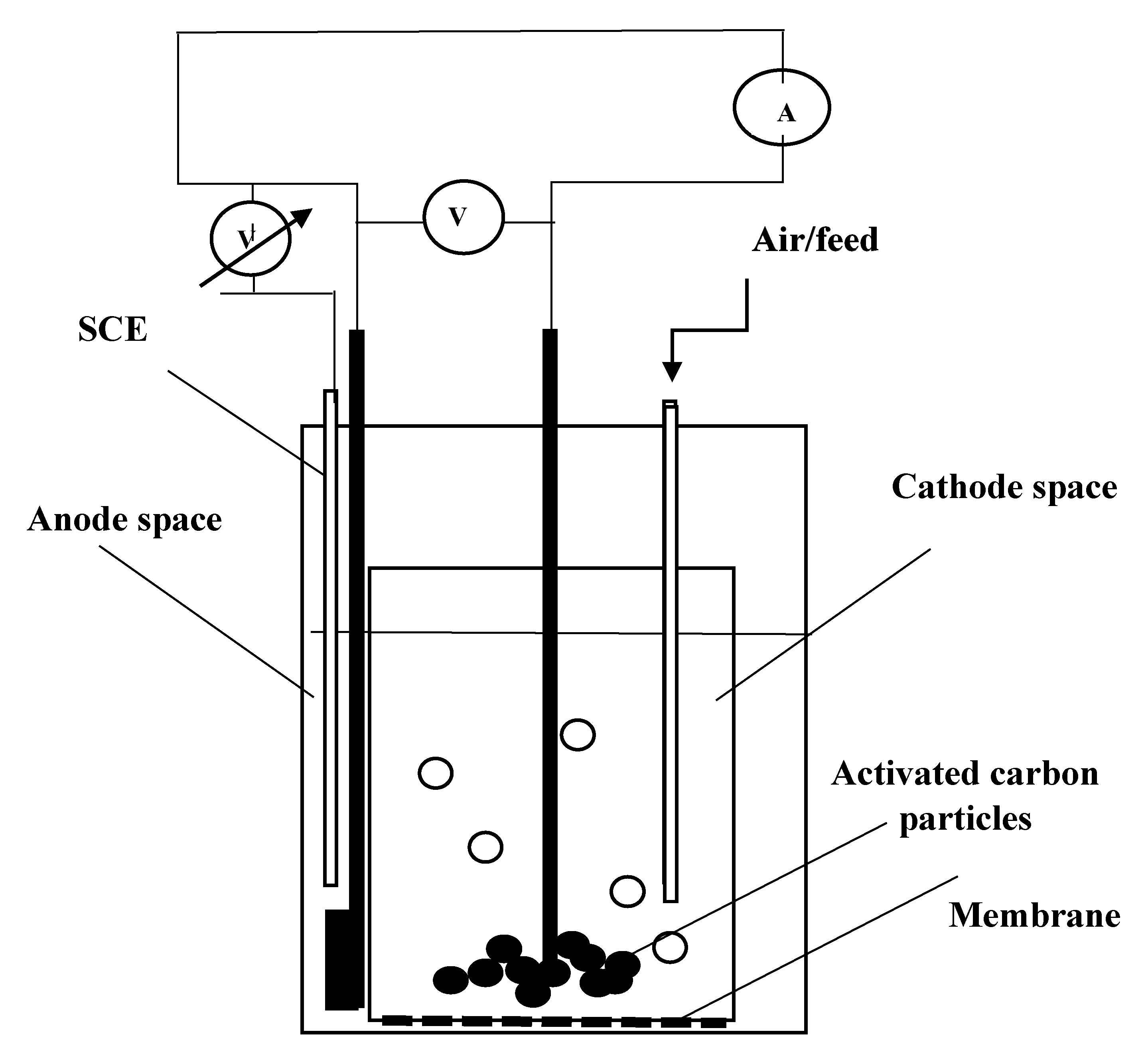
The voltammetric studies were carried out manually with and without cobalt spinel as the catalyst at different temperatures in a small-scale cylindrical fuel cell of 150 mL for the cathode space and 100 mL for the anode one. The cathode space was filled by particles of granulated activated carbon to enlarge the contact area. Carbon felt or granulated activated carbon were chosen as the anode. The experiments with felt were carried out with and without cobalt-spinel catalyst embedded within. The conduction contacts were graphite rods of spectral purity. A Celgard 3501 separation membrane with an area of 7 sq.cm was used. A sketch of this fuel cell is shown in Figure 10.
The anode potential Ua was measured vs. saturated calomel electrode (SCE). For maintenance of constant anode potential, a potentiostat DECM (Budapest, Hungary) was used. The electromotive force of the cell E = Uc − Ua and the current were also measured during the experiments.
The equilibrium anode potentials Ueq when the electric current was zero were estimated by the intercepts on the anode potential axis in the voltammetrric curves. Then the overpotentials η = Ua − Ueq were calculated and plotted versus the measured electric current. From these curves the exchange current i0 and the transfer coefficients αa and αc were estimated using the generalized Butler–Volmer equation, Equation (S1).
3.4. Fuel Cell Discharge Experiments
These experiments were carried out both in batch and continuous modes, see Figure 9. In the latter ones the sulfide solution was fed into the fuel cell (a single one or a stack) by a peristaltic dosage pump. The flow rate of the feeding solutions were 0.2 or 0.4 dm3 h−1 for the different runs. In these studies, graphite was used for the electrodes, besides one experiment when zirconia-doped carbon was used as anode. The generated electromotive force E = U1 − U2 was discharged through a selected ohmic resistance equal or close to the one of the fuel cell. The electric current, the cell tension and the open circuit potentials were monitored during the runs. During the runs, samples from the feeding solution and from the outlet stream were taken and analysed. The results of the analyses for the sulfide oxidation were compared to the ones calculated from the current values according to Faraday’s law, Equation (S2).
3.5. Analyses
Samples from the inlet solution in the fuel cell assembly and the outlet solution were taken regularly. They were analyzed for sulfide, sulfite and sulfate ions. The pH values of the feeding solutions and the outlet ones were measured by pH-meter. Sulfide was analyzed quantitatively by photometry with N,N-dimethyl-n-phenylene-diamine in the presence of Fe(III) giving methylene blue [21]. Sulfite was analyzed iodometrically. Sulfate ions were analyzed turbidimetrically after addition of barium chloride (APHA). The formation of polysulfides was checked qualitatively by acidification of the reaction mixture and deposition of elemental sulfur. The presence of thiosulfate was checked qualitatively by ferric chloride yielding an intensive purple complex.
The pH values of the feeds and the outlet streams from both compartments of the fuel cell were measured in the samples taken.
4. Conclusions
Based on the presented experimental results the following conclusions can be drawn.
- (1)
- It is possible to produce energy from hydrogen sulfide in marine water as a fuel. Its enthalpy of combustion is comparable to methane and hydrogen. The proposed approach enables direct production of electricity without intermediate processes, with sulfate ions as a product. The latter is compatible with the marine environment and, therefore, the method can be considered as waste-free.
- (2)
- The main drawback of the proposed method is the low current and power densities because of the low oxygen transfer rate and oxygen concentration in the cathode space. Hence, oxygen reduction appears to be the rate-determining step in the overall electrochemical process. This problem has to be solved by increasing oxygen partial pressure in the air and by introducing a suitable catalyst for oxygen reduction.
- (3)
- Another problem is due to the variety of reactions of sulfide oxidation. The present data show that the oxidation of sulfide to sulfate in the bulk is successful but there are parasite reactions of sulfide oxidation. Oxidation of sulfide to sulfite is also observed. That is why the anodic process should be carried out under oxygen-free conditions.
- (4)
- The practical application of this process will be promoted if suitable catalysts for selective sulfide to sulfate oxidation are developed and when the process of oxygen reduction is enhanced properly.
Supplementary Materials
The following are available online at https://www.mdpi.com/article/10.3390/catal11060694/s1, Figure S1, Butler-Volmer plot for carbon felt as anode with Co-spinel (■) and without it (◊). Figure S2, Polarization curve and power density dependence for a two cell stack. Continuous feed. Direct aeration. Figure S3, Time profile of cell voltage, open circuit potential (OCP) and electric current for a discharge of single fuel cell aerated by Venturi tube ejector. Figure S4, X-ray diffraction (XRD) diagram of the catalyst based on cobalt spinel. Figure S5, Energy-dispersive X-ray (EDX) spectrum of the sintered graphite electrode. Table S1, Comparison of the results for sulfide depletion rate with the calculated ones for different anode reactions.
Author Contributions
Conceptualization, V.N.B.; Methodology, V.N.B., E.N.R.-V., M.S.M.; Investigation, E.N.R.-V., S.M.S.; Writing—Original Draft Preparation: V.N.B.; Project Administration and Funding Acquisition, E.N.R.-V. All authors have read and agreed to the published version of the manuscript.
Funding
Ministry of Education and Science, Republic of Bulgaria, program Eplus, grant D01-214/2019.
Data Availability Statement
The data will be available after the project completion.
Conflicts of Interest
The authors declare no conflict of interest.
References
- Petrov, K.; Baykara, S.Z.; Ebrasu, D.; Gulin, M.; Veziroglu, A. An assessment of electrolytic hydrogen production from H2S in Black Sea waters. Int. J. Hydrog. Energy 2011, 6, 8936–8942. [Google Scholar] [CrossRef]
- Neklyudov, I.K.; Bortz, B.V.; Polevich, O.W.; Tkachenko, V.I.; Shilyaev, B.A. Alternative hydrogen sulfide energetics in the Black Sea. Part I. State of the art, problems and perspectives (in Russian). Int. Sci. J. Altern. Energy Ecol. 2006, 12, 23–30. [Google Scholar]
- Fornes, J.P.; Bisang, J.M. Cathode depassivation using ultrasound for the production of colloidal sulphur by reduction of sulphur dioxide. Electrochim. Acta 2016, 213, 186–193. [Google Scholar] [CrossRef]
- Dutta, P.K.; Rabaey, K.; Yuan, Z.; Keller, J. Spontaneous electrochemical removal of aqueous sulfide. Water Res. 2008, 42, 4965–4975. [Google Scholar] [CrossRef] [PubMed]
- Saad, E.G.; Zewail, T.M.; Zatout, A.A.; El-Ashtoukhy, E.-S.Z.; Abdel-Aziz, M.H. Electrochemical removal of sulfide ions and recovery of sulfur from sulfide ions containing wastes. J. Industr. Eng. Chem. 2021, 94, 390–396. [Google Scholar] [CrossRef]
- Zhai, L.-F.; Song, W.; Tong, Z.-H.; Sun, M. A fuel-cell-assisted iron redox process for simultaneous sulfur recovery and electricity production from synthetic sulfide wastewater. J. Hazard. Mater. 2012, 243, 350–356. [Google Scholar] [CrossRef] [PubMed]
- Zhang, B.; Zhang, J.; Liu, Y.; Hao, C.; Tian, C.; Feng, C.; Lei, Z.; Huang, W.; Zhang, Z. Identification of removal principles and involved bacteria in microbial fuel cells for sulfide removal and electricity generation. Int. J. Hydrog. Energy 2013, 38, 14348–14355. [Google Scholar] [CrossRef] [Green Version]
- Uzun, D.; Razkazova-Velkova, E.; Petrov, K.; Beschkov, V. H2S/O2 fuel cells using hydrogen sulfide from Black Sea waters. J. Appl. Electrochem. 2016, 46, 943–949. [Google Scholar] [CrossRef]
- Beschkov, V.; Razkazova-Velkova, E.; Martinov, M.; Stefanov, S. Electricity production from marine water by sulfide-driven fuel cell. Appl. Sci. 2018, 8, 1926. [Google Scholar] [CrossRef] [Green Version]
- Midilli, A.; Ay, M.; Kale, A.; Nejat Veziroglu, T. A parametric investigation of hydrogen energy potential based on H2S in Black Sea deep waters. Int. J. Hydrog. Energy 2007, 32, 117–124. [Google Scholar] [CrossRef]
- Demirbas, A. Hydrogen sulfide from the black sea for hydrogen production. Energy Sources Part A Recovery Util. Environ. Eff. 2009, 31, 1866–1872. [Google Scholar] [CrossRef]
- Suhotin, A.M. (Ed.) Guidebook on Electrochemistry (In Russian); Himia: Leningrad, Russia, 1981. [Google Scholar]
- Sanli, A.E.; Canan, B.; Aytaç, A. Use of the Black Sea water containing hydrogen sulfide (H2S) as a Fuel Cell Fuel. ECS Transactions 2015, 65, 51–58. [Google Scholar] [CrossRef]
- Uzun, D.; Razkazova-Velkova, E.; Petrov, K.; Beschkov, V. Electrochemical method for energy production from hydrogen sulfide in the Black Sea waters in sulfide-driven fuel cell. Bulg. Chem. Commun. 2015, 47, 859–866. [Google Scholar]
- Beschkov, V.; Razkazova-Velkova, E.; Martinov, M.; Stefanov, S. Energy production from black sea water by sulfide-driven fuel cell. In Proceedings of the 15th International Multidisciplinary Scientific Conference SGEM, Albena, Bulgaria, 18–24 June 2015; Energy and Clean Technologies. pp. 207–212. [Google Scholar]
- Kim, K.; Han, J.-I. Performance of direct alkaline sulfide fuel cell without sulfur deposition of anode. Int. J. Hydrog. Energy 2014, 39, 7142–7146. [Google Scholar] [CrossRef]
- Yang, H.-C.; Park, S.-K. Oxygen transfer characteristics of an ejector aeration system. Int. J. Fluid Mach. Syst. 2012, 5, 10–17. [Google Scholar] [CrossRef] [Green Version]
- Wang, S.; Zhang, L.; Xia, Z.; Roy, A.; Chang, D.W.; Baek, J.-B.; Dai, L. BCN graphene as efficient metal-free electrocatalyst for the oxygen reduction reaction. Angew. Chem. 2012, 51, 4209–4212. [Google Scholar] [CrossRef] [PubMed]
- Ljutzkanov, L.; Atanasov, A. Method for Treatment of Carbon-Containing Materials. BG Patent 63594/26.06.2002, 28 June 2002. [Google Scholar]
- Dermendzhieva, N.D.; Razkazova-Velkova, E.N.; Beschkov, V.N. Kinetics of oxidation of sulfide ions in model solutions of sea water. Bulg. Chem. Commun. 2015, 47, 766–770. [Google Scholar]
- Rees, T.D.; Gyllenpetz, A.B.; Docherty, A.C. The determination of trace amounts of sulphide in condensed steam with N-diethyl-P-phenylenediamine. Analyst 1971, 96, 201–208. [Google Scholar] [CrossRef]
Figure 1.
Principal sketch of sulfide driven fuel cell. (a) by proton transfer through the membrane; (b) by hydroxylic anion transfer through the membrane.
Figure 1.
Principal sketch of sulfide driven fuel cell. (a) by proton transfer through the membrane; (b) by hydroxylic anion transfer through the membrane.
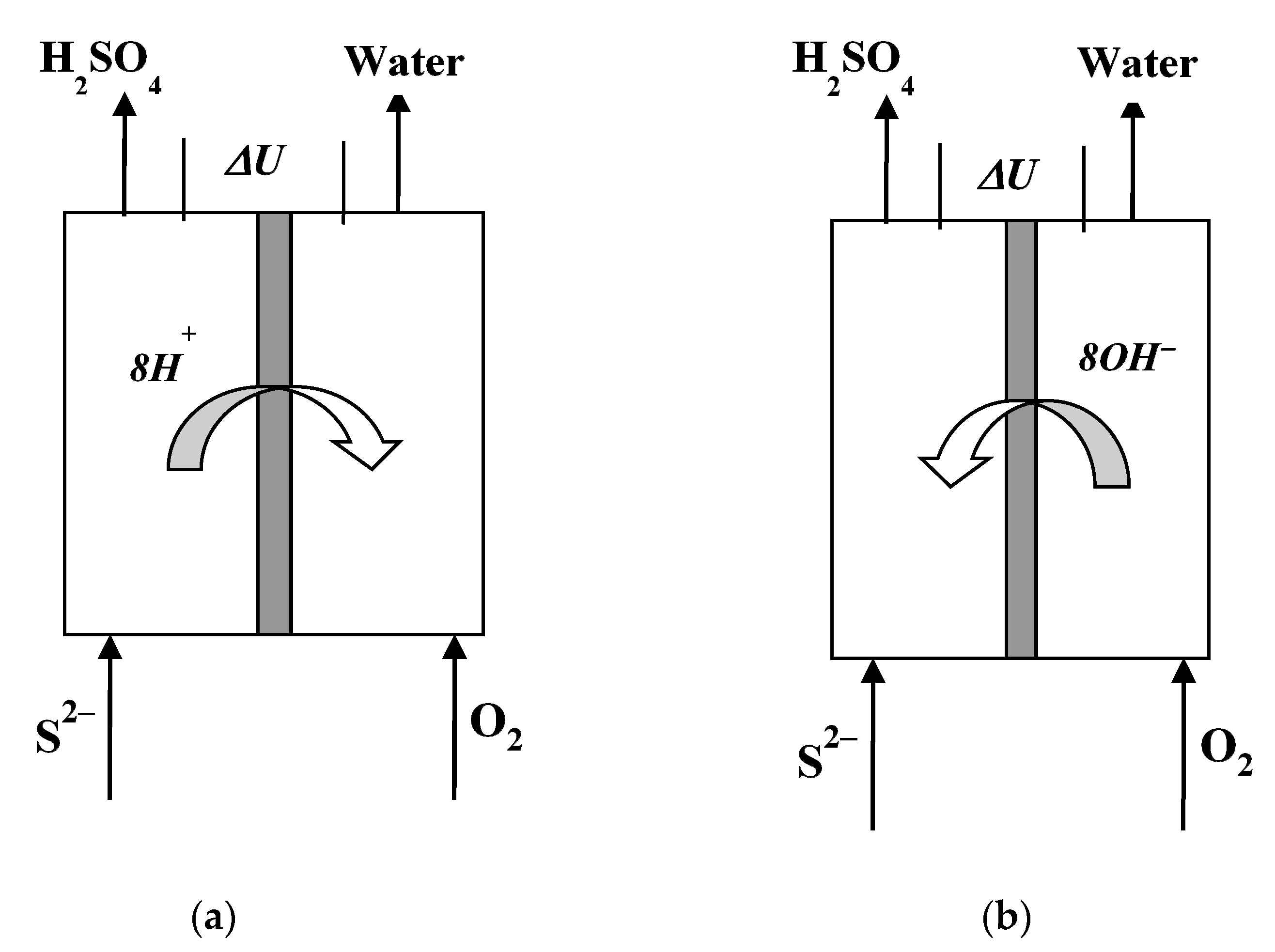
Figure 2.
Comparison of the voltammetric curves for carbon felt anode with cobalt spinel as catalyst (●) and without it (o). Batch process. Temperature 10 °C; sulfide concentration 63 mg dm−3.
Figure 2.
Comparison of the voltammetric curves for carbon felt anode with cobalt spinel as catalyst (●) and without it (o). Batch process. Temperature 10 °C; sulfide concentration 63 mg dm−3.

Figure 3.
Generated cell voltages at different sulfide concentrations. Single fuel cell. Batch process. Direct aeration. Solid line (o)—70 mg dm−3; dashed line (o)—240 mg dm−3; solid line (●)—670 mg dm−3.
Figure 3.
Generated cell voltages at different sulfide concentrations. Single fuel cell. Batch process. Direct aeration. Solid line (o)—70 mg dm−3; dashed line (o)—240 mg dm−3; solid line (●)—670 mg dm−3.

Figure 4.
Power densities generated in the fuel cell at different sulfide concentrations. Single fuel cell. Batch process. Direct aeration. Solid line (o)—70 mg dm−3; dashed line (o)—240 mg dm−3; solid line (●)—670 mg dm−3.
Figure 4.
Power densities generated in the fuel cell at different sulfide concentrations. Single fuel cell. Batch process. Direct aeration. Solid line (o)—70 mg dm−3; dashed line (o)—240 mg dm−3; solid line (●)—670 mg dm−3.

Figure 5.
Polarization curve and power density dependence for a single fuel cell with preliminary aeration in Venturi-tube ejector, feeding flow rate 1 dm3/h. (a) Continuous feed, sulfide concentration 190 mg dm−3; feeding flow rate 0.4 dm3/h. (b) Batch process, 260 mg dm−3.
Figure 5.
Polarization curve and power density dependence for a single fuel cell with preliminary aeration in Venturi-tube ejector, feeding flow rate 1 dm3/h. (a) Continuous feed, sulfide concentration 190 mg dm−3; feeding flow rate 0.4 dm3/h. (b) Batch process, 260 mg dm−3.

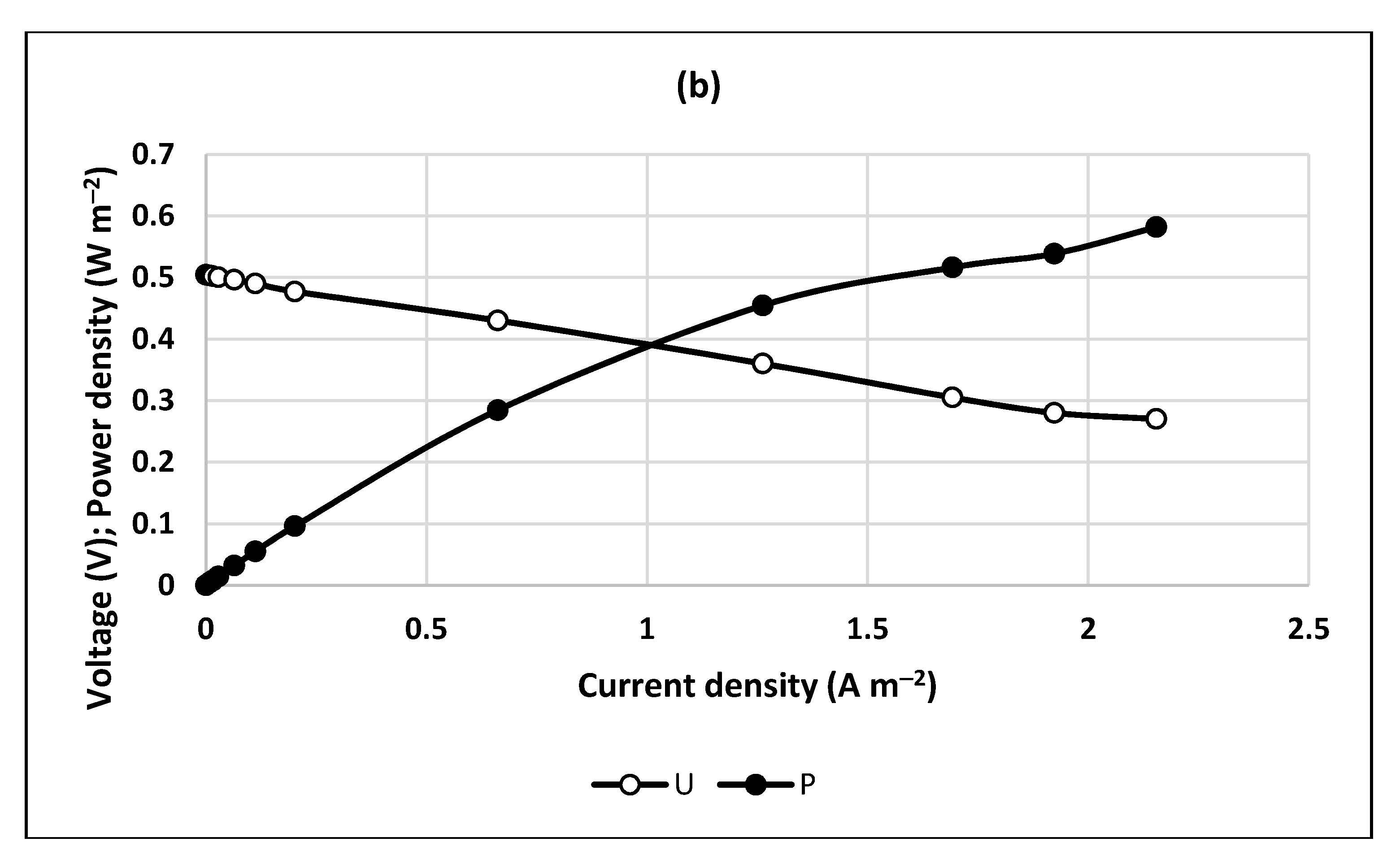
Figure 6.
Time profile of cell voltage, open circuit potential (OCP) and electric current for a discharge of a two fuel cell stack, aerated by direct aeration. Feeding flow rate for cathode compartments 1 dm−3/h each. Feeding sulfide concentration 77.1 mg dm−3. Feeding flow rate for anode compartment 0.4 dm3/h each. Load resistance 10 Ω. Temperature 20 °C.

Figure 7.
Ratios of the sulfide conversion rates calculated by Faraday’s law to the analytically determined ones (as 100%). Two types of aeration. Experimental conditions of run 5, Table S1.
Figure 7.
Ratios of the sulfide conversion rates calculated by Faraday’s law to the analytically determined ones (as 100%). Two types of aeration. Experimental conditions of run 5, Table S1.
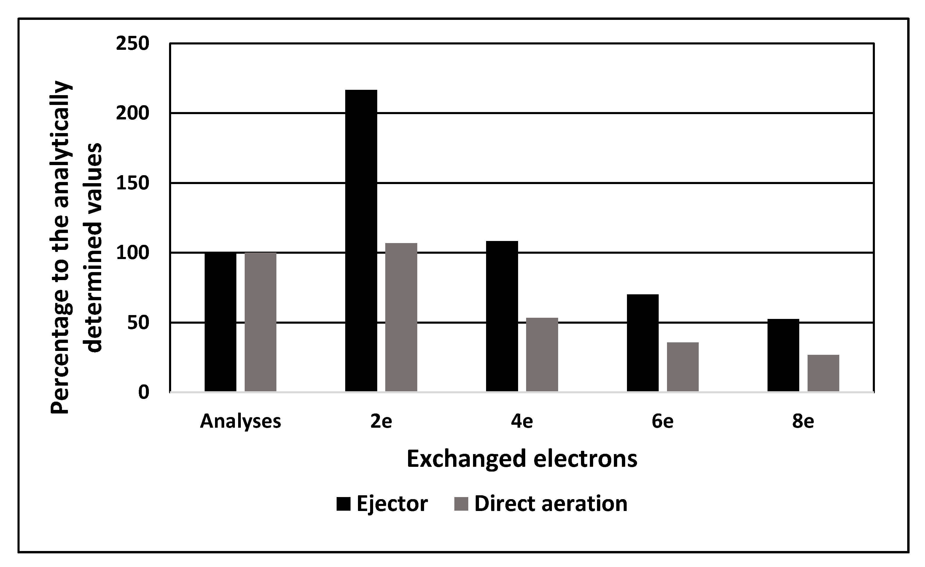
Figure 8.
Time profile of cell voltage, open circuit potential (OCP) and electric current for a discharge of a single fuel cell aerated by Venturi tube ejector. Anode is doped by zirconia. Feeding flow rate for cathode compartment 1 dm3/h. Feeding sulfide concentration 55.4 mg dm−3. Feeding flow rate 0.2 dm3 h−1. Load resistance 10 Ω. Temperature 20 °C.
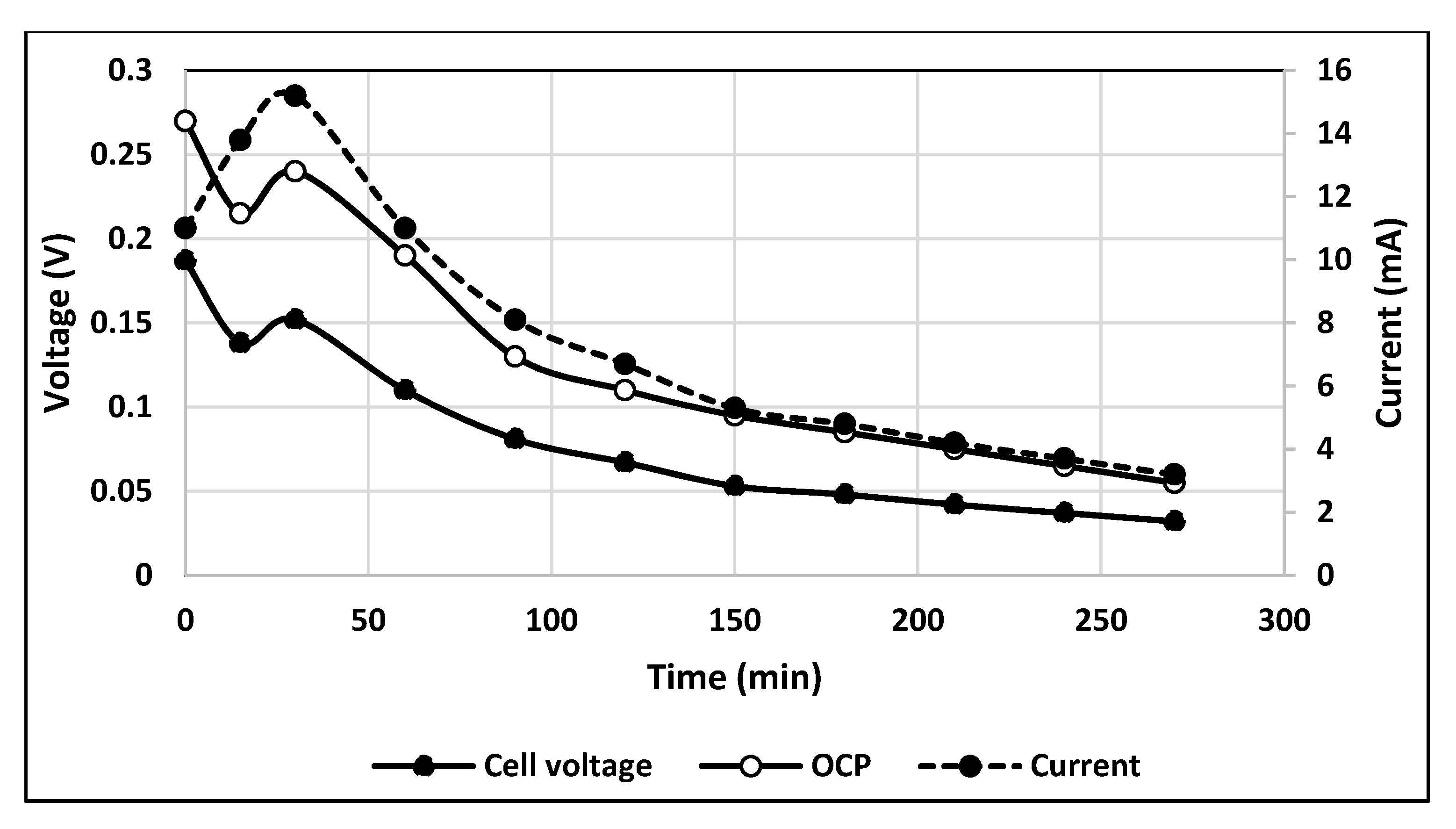
Figure 9.
A sketch of the fuel cell discharge assembly with direct aeration (a); the aeration system with Venturi tube ejector (b).
Figure 9.
A sketch of the fuel cell discharge assembly with direct aeration (a); the aeration system with Venturi tube ejector (b).
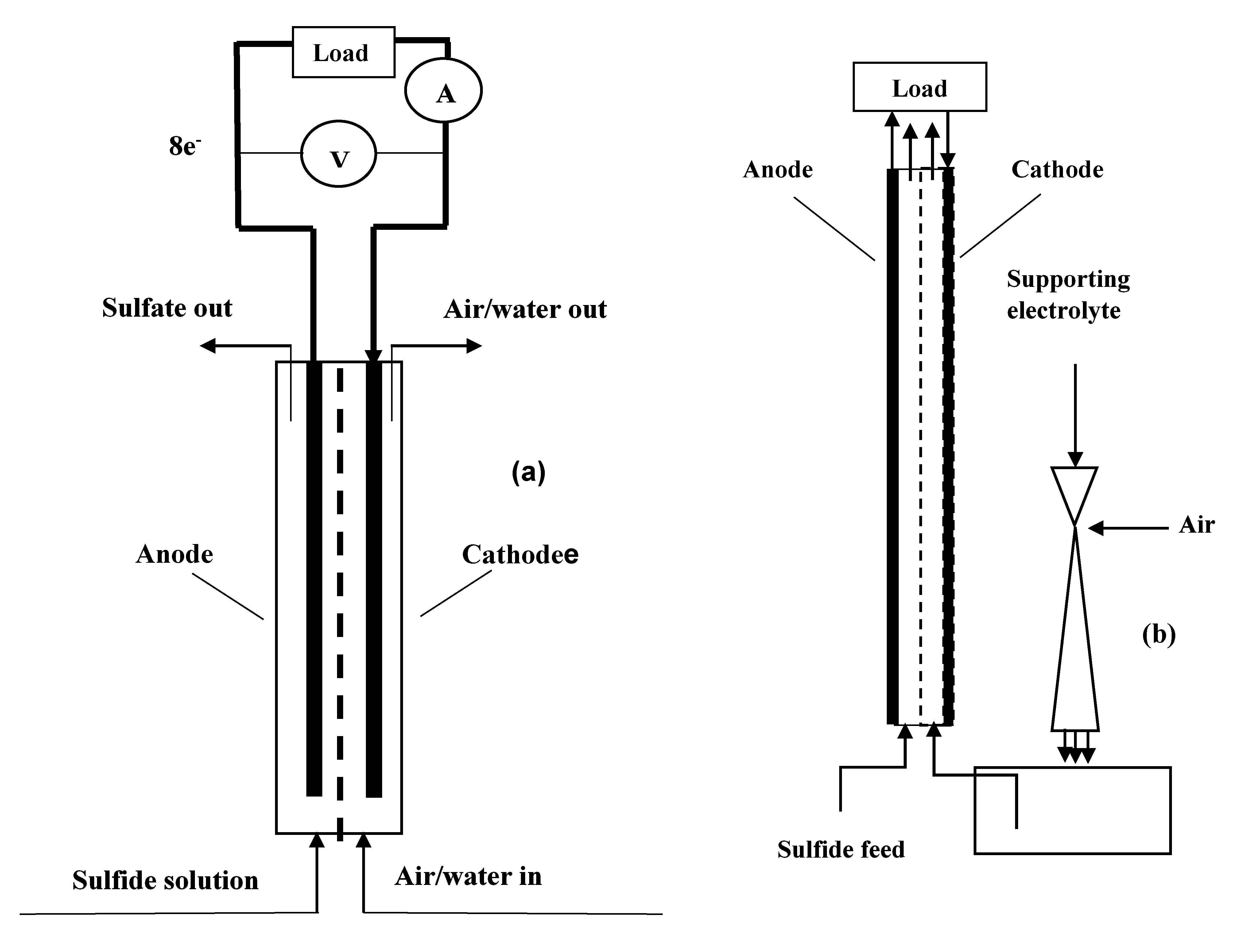
Figure 10.
A sketch of the cylindrical fuel cell used for voltammetric studies.

Table 1.
Short excerpt of sulfide oxidation reactions.
| No. | Reversible Redox Anode Reactions (Short Excerpt) | Number of Exchanged Electrons | Standard Electrode Potential (V), 25 °C |
|---|---|---|---|
| 1 | SO42− + H2O+ 2e = SO32− + 2OH− | 2 | −0.93 |
| 2 | SO32− + 3H2O + 6e = S2− + 6OH− | 6 | −0.66 |
| 3 | S22− + 2e = 2S2− | 2 | −0.524 |
| 4 | S + 2e = S2− | 2 | −0.33 |
| 5 | 2SO42− + 4H++ 2e = S2O62− + 2H2O | 2 | −0.22 |
| 6 | 2H2SO3(aq) +H++2e = HS2O4− +2H2O | 2 | −0.082 |
| 7 | S52− + 5H+ + 8e = 5HS− | 2 | 0.003 |
| 8 | S2O32− + 6H+ +8e = 2S2− + 3H2O | 4 | −0.006 |
| 9 | HSO3− + 5H+ + 4e = S +3H2O | 4 | 0 |
| 10 | S42− + 4H+ + 6e = 4HS | 6 | 0.033 |
| 11 | S32− + 3H+ + 4e = 3HS− | 4 | 0.090 |
| 12 | SO42− + 8H+ + 8e = S2− + 4H2O | 8 | 0.149 |
| 13 | SO32− + 6H++ 6e = S2− + 3H2O | 6 | 0.231 |
Table 2.
Kinetic data obtained for the anode compartment, packed with granulated activated carbon at different temperatures. Sulfide concentration 63 mg dm−3.
Table 2.
Kinetic data obtained for the anode compartment, packed with granulated activated carbon at different temperatures. Sulfide concentration 63 mg dm−3.
| Temperature, °C | Equilibrium Electrode Potential, V/S.H.E. | Transfer Coefficient, α (-) | Exchange Current i0, mA |
|---|---|---|---|
| 8 | 0.031 | 0.28 | 0.29 |
| −0.225 | 0.26 | 0.14 | |
| 14 | 0.03 | 0.26 | 9.2 |
| −0.235 | 0.26 | 1.5 | |
| 20 | 0.041 | 0.11 | 3.2 |
| −0.242 | 0.33 | 3.0 |
Table 3.
Kinetic data obtained for the anode compartment, with carbon felt as electrode with and without embedded cobalt spinel at different temperatures. Sulfide concentration 63 mg dm−3.
Table 3.
Kinetic data obtained for the anode compartment, with carbon felt as electrode with and without embedded cobalt spinel at different temperatures. Sulfide concentration 63 mg dm−3.
| No Catalyst | Cobalt Spinel Catalyst | |||||
|---|---|---|---|---|---|---|
| T (°C) | Equilibrium Electrode Potential (V/S.H.E.) | Transfer Coefficient α (-) | Exchange Current i0 (mA) | Equilibrium Electrode Potential (V/S.H.E.) | Transfer Coefficient α (-) | Exchange Current i0 (mA) |
| 6 | - | - | - | 0.0057 | 0.1 | 3.7 |
| - | - | - | −0.29 | 0.18 | 2.7 | |
| 10 | 0.200 | 0.084 | 0.032 | −0.014 | 0.070 | 1.9 |
| 0.235 | 0.18 | 0.071 | −0.093 | 0.11 | 0.014 | |
| 23 | −0.107 | 0.17 | 1.44 | - | - | - |
| −0.127 | 0.26 | 0.25 | - | - | - | |
| 24 | −0.086 | 0.13 | 3.6 | 0.092 | 0.11 | 3.45 |
| 0.218 | 0.17 | 2.9 | −0.193 | 0.14 | 0.51 | |
Publisher’s Note: MDPI stays neutral with regard to jurisdictional claims in published maps and institutional affiliations. |
© 2021 by the authors. Licensee MDPI, Basel, Switzerland. This article is an open access article distributed under the terms and conditions of the Creative Commons Attribution (CC BY) license (https://creativecommons.org/licenses/by/4.0/).
Share and Cite
MDPI and ACS Style
Beschkov, V.N.; Razkazova-Velkova, E.N.; Martinov, M.S.; Stefanov, S.M. Performance of Sulfide-Driven Fuel Cell Aerated by Venturi Tube Ejector. Catalysts 2021, 11, 694. https://doi.org/10.3390/catal11060694
AMA Style
Beschkov VN, Razkazova-Velkova EN, Martinov MS, Stefanov SM. Performance of Sulfide-Driven Fuel Cell Aerated by Venturi Tube Ejector. Catalysts. 2021; 11(6):694. https://doi.org/10.3390/catal11060694
Chicago/Turabian StyleBeschkov, Venko N., Elena N. Razkazova-Velkova, Martin S. Martinov, and Stefan M. Stefanov. 2021. "Performance of Sulfide-Driven Fuel Cell Aerated by Venturi Tube Ejector" Catalysts 11, no. 6: 694. https://doi.org/10.3390/catal11060694
Note that from the first issue of 2016, this journal uses article numbers instead of page numbers. See further details here.