
The Effect of Catalyst Calcination Temperature on Catalytic Decomposition of HFC-134a over γ-Al2O3
by
 , , and
Mahshab Sheraz
1,2,† ,
,
Ali Anus
1,† ,
,
Van Cam Thi Le
1,2,
Caroline Mercy Andrew Swamidoss
3 and
Seungdo Kim
1,2,4,* 1
Department of Environmental Sciences and Biotechnology, Hallym University, Chuncheon 24252, Korea
2
Nano-Innotek Corporation, 123, Digital-ro 26 gil, Guro-gu, Seoul 08390, Korea
3
Department of Chemistry, Dr. M.G.R. Educational and Research Institute, Chennai 600095, India
4
Environment Strategy Development Institute, Hallym University, Chuncheon 24252, Korea
*
Author to whom correspondence should be addressed.
†
Co-first authors.
Catalysts 2021, 11(9), 1021; https://doi.org/10.3390/catal11091021
Submission received: 27 July 2021
/
Revised: 10 August 2021
/
Accepted: 23 August 2021
/
Published: 24 August 2021
(This article belongs to the Special Issue State-of-the-Art Catalytical Technology in South Korea)
Abstract
:This paper explores the thermal and catalytic pyrolysis of HFC-134a over γ-Al2O3 calcined at temperatures of 550 °C (A550), 650 °C (A650), 750 °C (A750), and 850 °C (A850). The physicochemical properties of catalysts were studied through thermogravimetric analysis (TGA), Brunauer–Emmett–Teller equation for nitrogen physisorption analysis (BET), X-ray diffraction (XRD), and temperature-programmed desorption of ammonia (NH3-TPD). The non-catalytic pyrolysis of HFC-134a showed less than 15% decomposition of HFC-134a. Catalysts increased the decomposition as A650 revealed the highest decomposition efficiency by decomposing more than 95% HFC-134a for 8 h followed by A750, A850, and A550. The larger surface area and pore volume paired with a low amount of strong acidic sites were considered as the main contributors to the comparatively longer catalytic activity of A650.
1. Introduction
Global interest in greenhouse gases has risen recently due to global disasters such as the rising sea level, global warming, irregular global rainfall, etc. Since the 1880s, the National Aeronautics and Space Administration (NASA) has noted that the surface temperature has increased by 1.3 °C (~2.7 °F) [1]. The reason behind such disasters is related to human activities such as the use of greenhouse gases. Although human life has improved through the use of fluorinated greenhouse gases as refrigerants and in air conditioning systems [2], these gases have a very high global warming potential (GWP) compared to the other greenhouse gases [3]. Therefore, many researchers are investigating their reduction, destruction, and recycling [4]. The Montreal Protocol articulated a complete ban on the usage of chlorofluorocarbons as refrigerants, with hydrofluorocarbons also being on the list [5]. Among various hydrofluorocarbons, HFC-134a is the most extensively used coolant gas and its GWP is 1300 [5]. The Kyoto Protocol highlighted the seriousness of using HFC-134a and the Kigali amendment to the Montreal Protocol called for the reduction in its usage [6,7].
At present, techniques for the treatment of HFC-134a are also being investigated and various technologies, such as thermal combustion, plasma, and pyrolysis have been suggested as potential treatment methods. Thermal combustion is considered an established technology for the decomposition of HFCs and PFCs and it is also certified by UNFCCC to abate HFC-23 [8]. However, its commercialization has some obstacles due to the extremely high temperature achieved by the use of fuel. It is also challenging to find appropriate low-cost materials for the reaction chamber. The formation of toxic byproducts, such as the strongly corrosive HF and dioxin, suggests that post-treatment should be a viable alternative option [9,10,11].
Plasma technology is also growing rapidly in the field of decomposition of fluorinated compounds. It has been reported that 99.9% of HFC-134a and CF4 can be decomposed by the use of plasma technology [12]. Moreover, undesirable byproducts, such as COF2 have been reported to be controlled, and it is considered to be proficient in treating HFC-134a over a wide range of initial concentrations [13,14,15,16]. However, the high initial operating costs coupled with low energy efficiency restrain the dominance of this technology.
Pyrolysis is an effective technology that can decompose HFC-134a at a lower temperature (750 °C) than plasma technology [17]. Catalytic pyrolysis has proven to be a safe, practical, and convenient method as it requires a comparatively lower temperature than other techniques, making the process cost-effective. Research on the catalytic pyrolysis of HFC-134a showed a high conversion rate when waste concrete was used as a catalyst at 600 °C and calcium fluoride was found to be the major product [17]. Metal phosphate catalysts were also applied to the decomposition of HFC-134a and were found to be successful as catalysts [18]. Researchers also reported the influence of Lewis acidity on the dehydrofluorination of 1,1,1,2-tetrafluoroethane [19]. The catalytic decomposition of 1,1,1,2-tetrafluoroethane to yield TrFE using a NiO/Al2O3 catalyst was also reported. However, the conversion rate using this catalyst was significantly lower [20]. The catalytic conversion of HFC-134a over γ-Al2O3-B was suggested as an effective process, leading to a high conversion rate [21]. Recent research showed that Mg-doped Alumina exhibited a higher decomposition efficacy than γ-Al2O3 for HFC-134a decomposition and the importance of calcination temperature was also emphasized [22].
The effect of calcination temperature on the catalysts for the effective decomposition of greenhouse gases was investigated by Jia et al. [19]. It was found that the decomposition efficiency of Al2O3 differed at different calcination temperatures as the number of acidic sites and the phases of Al2O3 were altered by a change in the calcination temperature. Among Al2O3 catalysts differing in their phase, θ-Al2O3 was revealed to have the highest efficiency for the decomposition of HFC-134a. Therefore, a more detailed study of the different decomposition patterns of HFC-134a over Al2O3 calcined at different temperatures would be very interesting. Furthermore, it is crucial to study the influence of surface properties and acidic sites on the catalyst lifetime.
Hence, the pyrolysis of HFC-134a over γ-Al2O3 calcined at different temperatures, 550 °C (A550), 650 °C (A650), 750 °C (A750), and 850 °C (A850) was investigated in this study. The acidity, pore size, surface area, and phase of Al2O3 calcined at different temperatures were analyzed using NH3-TPD, BET, and XRD. The decomposition tendency of HFC-134a over four γ-Al2O3 calcined at different calcination temperatures was determined using a vertical plug flow reactor coupled with a Gas Chromatography and Mass Spectrometry system.
2. Results and Discussion
2.1. Catalytic Pyrolysis of HFC-134a
The results from non-catalytic and catalytic pyrolysis of HFC-134a at 600 °C over different γ-Al2O3 catalysts are shown in Figure 1. It was observed that the non-catalytic decomposition rate of HFC-134a was lower than 15% at 600 °C. The non-catalytic decomposition of HFC-134a has also been reported in [17], where it was indicated that a high reaction temperature (750 °C) is required to facilitate a decomposition rate of more than 99%. The catalytic decomposition of HFC-134a at 600 °C was higher than 99% with all catalysts at the initial stage of the reaction. High conversion of HFC-134a over all the γ-Al2O3 catalysts was steady until around 5 h of reaction time and then decreased to less than 20% after 10 h in all cases except A650. The decomposition rate was maintained at more than 95% for 8 h over A650. The other γ-Al2O3 catalysts were found to be deactivated before 8 h, which resulted in the decomposition of a lesser amount of HFC-134a compared with A650.
The relative quantities of trifluoroethylene (TrFE, HFO-1123), which is formed as the main product, and the byproduct carbon dioxide are presented in Figure 2. TrFE forms due to the elimination of HF from HFC-134a as given in Equation (1). TrFE is a useful and expensive monomer compound that can be used for the production of functional fluoropolymers (fluoro-rubber and fluoro-plastic) and also used in intermediate material for biologically active compounds [19,23]. TrFE is an attractive refrigerant because its performance is comparable to traditional refrigerant (HFC-134a), but interestingly it has extremely low global warming potential (GWP = 0.3), which makes it an environment-friendly gas [24]. Although TrFE can be generated by other processes such as the hydrodechlorination of trichlorotrifluoroethane, its cost is proving to be an obstacle, limiting its chances of commercialization [25,26]. It was detected that A750 had the highest selectivity for TrFE followed by A850, A550, and A650, respectively. Although selectivity was higher with A750, TrFE production with A650 was higher in total due to a longer conversion time. A similar trend was also observed in the case of CO2. A750 and A850 produced more CO2 than the other two. CO2 might have been formed due to the gas-solid reaction between γ-Al2O3 and HFC-134a, as shown in Equation (2).
CH2FCF3 → CHF = CF2 + HF
CH2FCF3 + Al2O3 → C + CO2 + H2O + HF + AlF3
2.2. Physico-Chemical Properties of Catalysts
Figure 3 depicts the XRD patterns of fresh Al2O3 calcined at different temperatures. The patterns showed the characteristic peaks of γ-Al2O3, at 2θ 46.6°, 60.9°, and 67.1° in all the prepared catalysts. In addition to γ-phase, A850 also showed the characteristic peaks of θ-Al2O3 at 2θ 19.5°, 31.3°, 31.6°, 32.7°, 36.6°, 50.9°, 60.2°, and 62.5°.
Figure 4 depicts the XRD pattern of the spent γ-Al2O3, which were procured from the furnace after the progressive catalytic pyrolysis of HFC-134a. The typical XRD patterns of AlF3, XRD peaks at 2θ 25.2°, 42.5°, 51.8°, and 58.0°, were observed on all the spent γ-Al2O3 catalysts, suggesting the conversion of γ-Al2O3 to AlF3 during the catalytic pyrolysis of HFC-134a which is one of the two main reasons of γ-Al2O3 deactivation. Based on the product distribution and the conversion of γ-Al2O3 to AlF3, the catalytic pyrolysis reaction pathway of HFC-134a over γ-Al2O3 can be predicted as given in Equations (2) and (3).
6HF + Al2O3 → 2AlF3 + 3H2O
Figure 5 and Table 1 illustrate the acidic sites of the prepared catalysts with the help of ammonia temperature-programmed desorption. According to the previous literature, the ammonia desorption temperature region was divided into three zones, T ≤ 250 °C, 250 < T < 400 °C, and T > 400 °C. These zones were designated as weak acidic sites, moderate acidic sites, and strong acidic sites, respectively [27]. The NH3-TPD curves of γ-Al2O3 indicated that A550 and A850 have a larger amount of strong acidic sites. An escalation in the amount of strong acidic sites leads to higher coke formation and a reduction in the efficiency of the catalyst [19]. The coke amount of all the catalysts can also be seen in Table 1. It was observed that A850 produced the largest amount of coke followed by A550, A650, and A750. This coke formation agrees with the sequence of strong acidic sites. Coke formation is one of the reasons for catalyst deactivation due to pore blockage [28].
A750 possesses the largest amount of weak acidic sites among prepared catalysts. When observing the ratio between weak acidic sites and strong acidic sites, the ratio in A750 was also observed to be the highest. Weak acidic sites assist in the formation of TrFE by the elimination of HF [19]. Figure 6 gives the relationship between weak acidic sites and the production of TrFE (average TrFE formed till 95% conversion). It was found that the formation of TrFE was linearly related to the amount of weak acidic sites. The catalyst having a higher amount of weak acidic sites produced higher TrFE. The formation of CO2 was also found to be higher in catalysts with a higher amount of weak acidic sites. It is suggested that the gas-solid reaction (as shown in Equation (2)) is also dependent on weak acidic sites. Figure S1 in the Supplementary Information shows HFC-134a conversion with TrFE formation.
The BET surface areas of fresh catalysts are shown in Table 2. It was observed that the BET surface area of the catalysts decreases with the increase in calcination temperature as is also reported in the existing study [29]. It suggests that the calcination temperature causes catalyst aggregation which results in a change in catalyst properties. Y. Ding et al. concluded that high calcination temperature can collapse and block the pores and also can cause sintering, which ultimately causes loss in activity [30]. Catalytic performance can also be affected by pore properties [31,32]. Table 2 indicates that A650 has almost the same surface area as A550, and has the highest pore volume among other prepared catalysts. The type IV adsorption isotherm of A650 can be seen in the Supplementary Information as Figure S2. Alumina calcined at different temperatures and irrespective of the phase was reported to show type IV isotherms by the classification of IUPAC [19].
The catalytic decomposition of HFC-134a over A650 was maintained at a higher conversion rate for a more extended period than the other γ-Al2O3 catalysts. This superior performance of A650 is suggested to be due to its larger BET surface area, larger pore volume, and a smaller amount of strong acidic sites as compared to others. The strong acidic sites lead to accelerated coke formation and the lifetime of the catalyst tends to be decreased by the coke accumulation in the pores of the catalyst. Although the surface area of A550 was observed to be similar to A650, A550 showed a larger number of strong acidic sites, which accelerated the coke deposition resulting in a loss in activity and cause catalyst deactivation as shown in Figure 1. Contrarily, the strong acidic sites in A750 were less than A650 and weak acidic sites were significantly higher, the surface area and pore volume of A750 were detected to be smaller than A650. All these surface characteristics are considered to be the contributing factors that play a major part in prolonging the catalyst lifetime of A650 because the deactivation due to pore blockage from coke and AlF3 formation will take a longer time. The above results suggest that the usage of A650 for the catalytic pyrolysis of HFC-134a is more efficient than the γ-Al2O3 catalysts calcined at other temperatures. Pore properties were also reported to have an effect on catalytic activity [33].
3. Experimental Section
HFC-134a was purchased from RIGAS Co. Ltd. (Daejeon, Korea) and commercial γ-Al2O3 was purchased from Sasol, (Hamburg, Germany). CaO was used as HF capture and was acquired from Junsei Chemicals, (Tokyo, Japan). The catalysts were calcined at temperatures 550, 650, 750, and 850 °C for 2 h in the air by using a muffle furnace. After the calcination, the catalysts were crushed and sieved to make particles size between 1.0 and 1.7 mm.
The catalytic pyrolysis of HFC-134a over γ-Al2O3 calcined at different temperatures was carried out by a vertical plug flow reactor coupled with a gas chromatography–mass spectrometry system as shown in the previous study [22]. The entire system was comprised of a gas supply, reactor, HF trap, and the gas chromatograph–mass spectrometer. For the catalytic pyrolysis reaction, γ-Al2O3 (1.2 g) was taken as the catalyst bed and 100 mL/min of the mixture gas (2 mL/min HFC-134a and 98 mL/min nitrogen) was delivered to the system. The flow rates of HFC-134a and nitrogen were controlled by individual mass flow controllers. After the system was stabilized at 600 °C, the catalytic pyrolysis commenced by the initial supply of HFC-134a reactant gas. The gas hourly space velocity was 1667 h−1 and the weight hourly space velocity of the system was calculated as 5000 mL g−1cath−1. The product gas, which emanated from the reactor, was transferred to a valve GC/MS system (7890A/5975C inert, Agilent Technology, Santa Clara, CA, USA) through an HF trap containing CaO. Each peak on the GC/MS chromatogram was identified by associating it with that in the MS library (NIST 08th). The conversion rate (%) of HFC-134a was determined using Equation (4).
where Ain and Aout are the peak area of HFC-134a in the reactant gas and the product gas respectively.
Conversion rate (%) = (1 − Aout/Ain) × 100
Pore volume and surface area were measured from nitrogen sorption isotherms at 77 K using Barrett–Joyner–Halenda (BJH) desorption method and Brunauer–Emmett–Teller (BET) method, respectively. Nitrogen sorption isotherms were obtained with an Autosorb-iQ 2ST/MP apparatus (Quantachrome Instruments). All the samples were degassed for one hour at 300 °C before measurements. Ultima IV system (Rigaku) was used to study the structure of the catalysts by XRD over a 2θ scan range of 10–80° at 40 kV and 40 mA. The coke amount on catalysts was analyzed by TGA (Perkin Elmer) at the temperature range of 40–800 °C with 10 °C/min heating rate in the air. NH3-TPD was conducted by Micromeritics Autochem II 2920 analyzer (Norcross) to quantify the acidic sites of the catalysts. The desorption NH3 was analyzed from 100 to 700 °C at a rate of 10 °C/min.
4. Conclusions
γ-Al2O3 was calcined at 550, 650, 750, and 850 °C and was used as a catalyst for the pyrolysis of HFC-134a. A650 was able to maintain the decomposition rate for more than 95% for 8 h whereas, the decomposition rate was found to be less than 15% without the catalyst. It was observed that A650 has a low amount of strong acidic sites, larger surface area, and bigger pore volume which aided in maintaining the HFC-134a decomposition for a longer interval. A linear, direct relationship was found between the formation of TrFE and the weak acidic sites. A750 holds the highest amount of weak acidic sites and was able to produce the highest amount of TrFE. Similarly, the coke amount followed the same sequence as strong acidic sites, suggesting the influence of strong acidic sites on coke formation. A850 with the highest amount of strong acidic sites produced the largest amount of coke.
Supplementary Materials
The following are available online at https://www.mdpi.com/article/10.3390/catal11091021/s1, Figure S1: HFC-134a conversion rate and TrFE formation rate, Figure S2: The N2 adsorption isotherm of A650.
Author Contributions
M.S. and A.A. conducted all the experiments and wrote the original draft, C.M.A.S. and V.C.T.L. revised the manuscript. S.K. revised and edited the manuscript. All authors have read and agreed to the published version of the manuscript.
Funding
This work is financially supported by the Korea Ministry of Environment as Waste to Energy-Recycling Human Resource Development Project (YL-WE-21-001).
Data Availability Statement
All relevant data are within the paper.
Acknowledgments
We thank Tailer D. Cartwright for her contribution to the English improvement of this manuscript.
Conflicts of Interest
The authors declare no conflict of interest.
References
- Global Temperature in 2020. Available online: https://mailchi.mp/caa/global-temperature-in-2020?e=670df34344 (accessed on 22 April 2021).
- Srinivasan, J. Climate change, greenhouse gases and aerosols. Resonance 2008, 13, 1146–1155. [Google Scholar] [CrossRef]
- Meyer, L. IPCC Fifth Assessment Report Synthesis Report. Bogazici Univ. 2015, 10, 2015. [Google Scholar]
- de Richter, R.; Ming, T.; Davies, P.; Liu, W.; Caillol, S. Removal of non-CO2 greenhouse gases by large-scale atmospheric solar photocatalysis. Prog. Energy Combust. Sci. 2017, 60, 68–96. [Google Scholar] [CrossRef]
- Velders, G.J.M.; Andersen, S.O.; Daniel, J.S.; Fahey, D.W.; McFarland, M. The importance of the Montreal Protocol in protecting climate. Proc. Natl. Acad. Sci. USA 2007, 104, 4814–4819. [Google Scholar] [CrossRef] [Green Version]
- French, D. Kyoto Protocol to the United Nations Framework Convention on Climate Change. J. Environ. Law 1998, 10, 215–224. [Google Scholar] [CrossRef]
- Purohit, P.; Höglund-Isaksson, L.; Dulac, J.; Shah, N.; Wei, M.; Rafaj, P.; Schöpp, W. Electricity savings and greenhouse gas emission reductions from global phase-down of hydrofluorocarbons. Atmos. Chem. Phys. 2020, 20, 11305–11327. [Google Scholar] [CrossRef]
- Hayashi, D.; Michaelowa, A. Lessons from submission and approval process of large-scale energy efficiency CDM methodologies. HWWI Res. Pap. 2007, 4–11. Available online: https://www.econstor.eu/handle/10419/48262 (accessed on 23 August 2021).
- He, X.; Han, J.; Mi, T.; Qin, L. Investigation of HFC-134a decomposition by combustion and its kinetic characteristics in a laboratory scale reactor. Environ. Prot. Eng. 2015, 41, 143–150. [Google Scholar] [CrossRef]
- Han, W.; Li, Y.; Tang, H.; Liu, H. Treatment of the potent greenhouse gas, CHF 3—An overview. J. Fluor. Chem. 2012, 140, 7–16. [Google Scholar] [CrossRef]
- Shin, M.; Jang, D.; Lee, Y.; Kim, Y.; Kim, E. Comprehensive modeling of HFC-23 incineration in a CDM incinerator. J. Mater. Cycles Waste Manag. 2017, 19, 754–762. [Google Scholar] [CrossRef]
- Ohno, M.; Ozawa, Y.; Ono, T. Decomposition of HFC134a Using Arc Plasma. Int. J. Plasma Environ. Sci. Technol. 2007, 1, 159–165. [Google Scholar]
- Mok, Y.S.; Demidyuk, V.; Whitehead, J.C. Decomposition of hydrofluorocarbons in a dielectric-packed plasma reactor. J. Phys. Chem. A 2008, 112, 6586–6591. [Google Scholar] [CrossRef]
- Jasiński, M.; Dors, M.; Mizeraczyk, J. Destruction of freon HFC-134a using a nozzleless microwave plasma source. Plasma Chem. Plasma Process. 2009, 29, 363–372. [Google Scholar] [CrossRef]
- Narengerile; Saito, H.; Watanabe, T. Decomposition of tetrafluoromethane by water plasma generated under atmospheric pressure. Thin Solid Film. 2009, 518, 929–935. [Google Scholar] [CrossRef]
- Gaikwad, V.; Kennedy, E.; Mackie, J.; Holdsworth, C.; Molloy, S.; Kundu, S.; Stockenhuber, M.; Dlugogorski, B. Reaction of dichloromethane under non-oxidative conditions in a dielectric barrier discharge reactor and characterisation of the resultant polymer. Chem. Eng. J. 2016, 290, 499–506. [Google Scholar] [CrossRef] [Green Version]
- Iizuka, A.; Ishizaki, H.; Mizukoshi, A.; Noguchi, M.; Yamasaki, A.; Yanagisawa, Y. Simultaneous decomposition and fixation of F-gases using waste concrete. Ind. Eng. Chem. Res. 2011, 50, 11808–11814. [Google Scholar] [CrossRef]
- Takita, Y.; Tanabe, T.; Ito, M.; Ogura, M.; Muraya, T.; Yasuda, S.; Nishiguchi, H.; Ishihara, T. Decomposition of CH2FCF3 (134a) over metal phosphate catalysts. Ind. Eng. Chem. Res. 2002, 41, 2585–2590. [Google Scholar] [CrossRef]
- Jia, W.; Wu, Q.; Lang, X.; Hu, C.; Zhao, G.; Li, J.; Zhu, Z. Influence of Lewis Acidity on Catalytic Activity of the Porous Alumina for Dehydrofluorination of 1,1,1,2-Tetrafluoroethane to Trifluoroethylene. Catal. Lett. 2015, 145, 654–661. [Google Scholar] [CrossRef]
- Jia, W.; Liu, M.; Lang, X.; Hu, C.; Li, J.; Zhu, Z. Catalytic dehydrofluorination of 1,1,1,2-tetrafluoroethane to synthesize trifluoroethylene over a modified NiO/Al2O3 catalyst. Catal. Sci. Technol. 2015, 5, 3103–3107. [Google Scholar] [CrossRef]
- Han, T.U.; Yoo, B.S.; Kim, Y.M.; Hwang, B.A.; Sudibya, G.L.; Park, Y.K.; Kim, S. Catalytic conversion of 1,1,1,2-tetrafluoroethane (HFC-134a). Korean J. Chem. Eng. 2018, 35, 1611–1619. [Google Scholar] [CrossRef]
- Swamidoss, C.M.A.; Sheraz, M.; Anus, A.; Jeong, S.; Park, Y.K.; Kim, Y.M.; Kim, S. Effect of Mg/Al2O3 and calcination temperature on the catalytic decomposition of HFC-134a. Catalysts 2019, 9, 270. [Google Scholar] [CrossRef] [Green Version]
- Saiki, T.; Sumida, M.; Nakano, S.; Murakami, K. Method for Producing Trifluoroethylene. U.S. Patent 5,283,379, 1 February 1994. [Google Scholar]
- Ito, M.; Kurokawa, N.; Dang, C.; Hihara, E. Disproportionation reaction of HFO-1123 refrigerant. In Proceedings of the Refrigeration Science and Technology, Purdue, IN, USA, 9–12 July 2018. [Google Scholar]
- Mori, T.; Yasuoka, T.; Morikawa, Y. Hydrodechlorination of 1,1,2-trichloro-1,2,2-trifluoroethane (CFC-113) over supported ruthenium and other noble metal catalysts. Catal. Today 2004, 88, 111–120. [Google Scholar] [CrossRef]
- Ohnishi, R.; Wang, W.L.; Ichikawa, M. Selective hydrodechlorination of CFC-113 on Bi- and Tl-modified palladium catalysts. Appl. Catal. AGen. 1994, 113, 29–41. [Google Scholar] [CrossRef]
- Wahyuni, S.; Kunarti, E.S.; Swasono, R.T.; Kartini, I. Characterization and Photocatalytic Activity of TiO2(rod)-SiO2-Polyaniline Nanocomposite. Indones. J. Chem. 2018, 18, 321. [Google Scholar] [CrossRef] [Green Version]
- Weckhuysen, B.M.; Wachs, I.E. Chapter 11—CATALYSIS BY SUPPORTED METAL OXIDES. Handb. Surf. Interfaces Mater. 2001, 1, 613–648. [Google Scholar] [CrossRef] [Green Version]
- Inmanee, T.; Pinthong, P.; Jongsomjit, B. Effect of calcination temperatures and mo modification on nanocrystalline (γ-χ)-Al2O3 catalysts for catalytic ethanol dehydration. J. Nanomater. 2017, 2017, 5018384. [Google Scholar] [CrossRef] [Green Version]
- Ding, Y.; Zhao, C.; Li, Y.; Ma, Z.; Lv, X. Effect of calcination temperature on the structure and catalytic performance of the cu-mcm-41 catalysts for the synthesis of dimethyl carbonate. Quim. Nova 2018, 41, 1156–1161. [Google Scholar] [CrossRef]
- Jin, M.H.; Oh, D.; Park, J.H.; Lee, C.B.; Lee, S.W.; Park, J.S.; Lee, K.Y.; Lee, D.W. Mesoporous silica supported Pd-MnOx catalysts with excellent catalytic activity in room-temperature formic acid decomposition. Sci. Rep. 2016, 6, 33502. [Google Scholar] [CrossRef]
- Iwamoto, M.; Tanaka, Y.; Sawamura, N.; Namba, S. Remarkable Effect of Pore Size on the Catalytic Activity of Mesoporous Silica for the Acetalization of Cyclohexanone with Methanol. J. Am. Chem. Soc. 2003, 125, 13032–13033. [Google Scholar] [CrossRef]
- Hongmanorom, P.; Luengnaruemitchai, A.; Chollacoop, N.; Yoshimura, Y. Effect of the Pd/MCM-41 Pore Size on the Catalytic Activity and cis–trans Selectivity for Partial Hydrogenation of Canola Biodiesel. Energy Fuels 2017, 31, 8202–8209. [Google Scholar] [CrossRef]
Figure 1.
Thermal and catalytic conversion rate of HFC-134a over γ-Al2O3.

Figure 2.
Formation rate of (a) TrFE and (b) CO2 during the catalytic decomposition of HFC-134a.
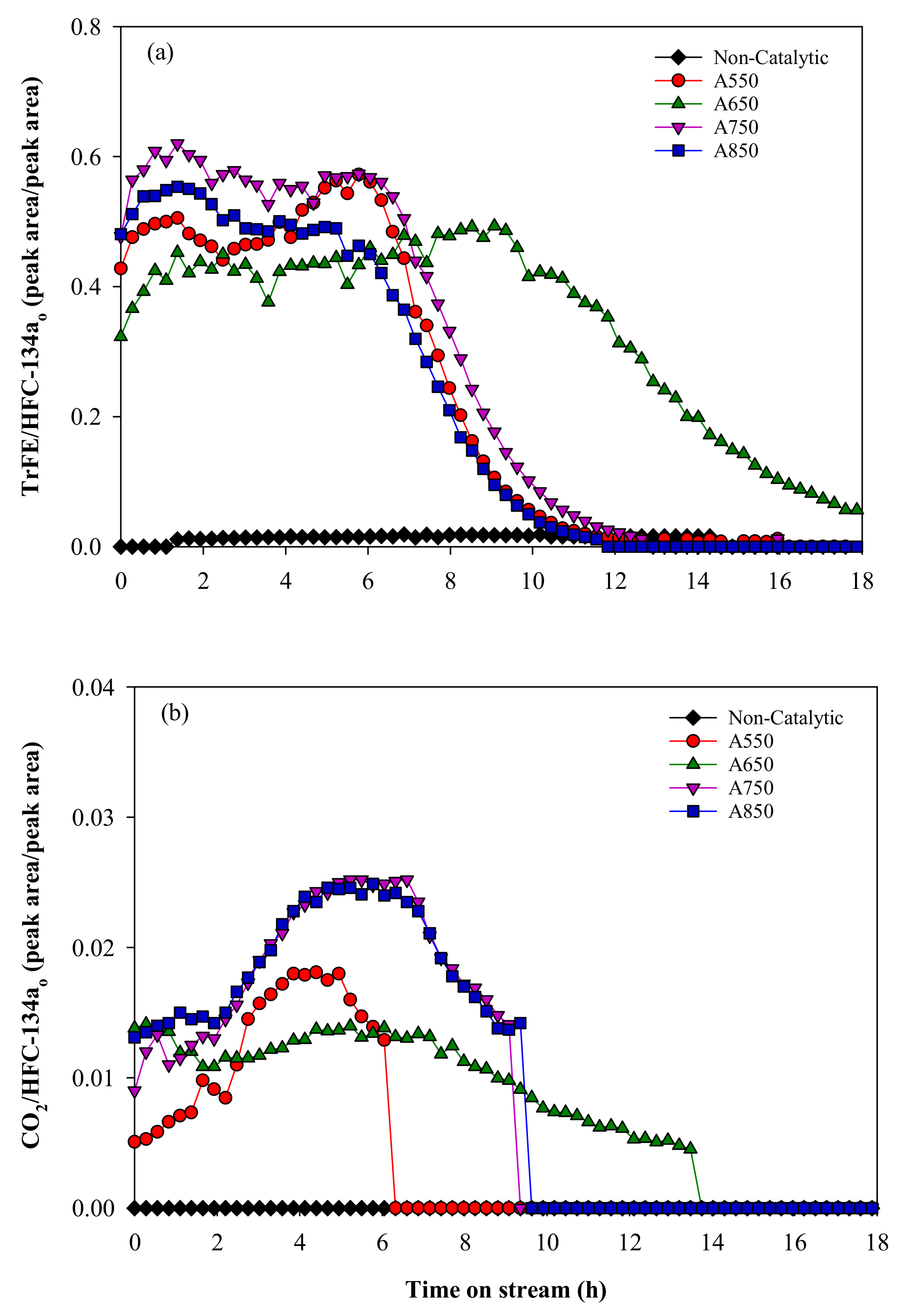
Figure 3.
XRD patterns of γ-Al2O3 obtained at different calcination temperatures.
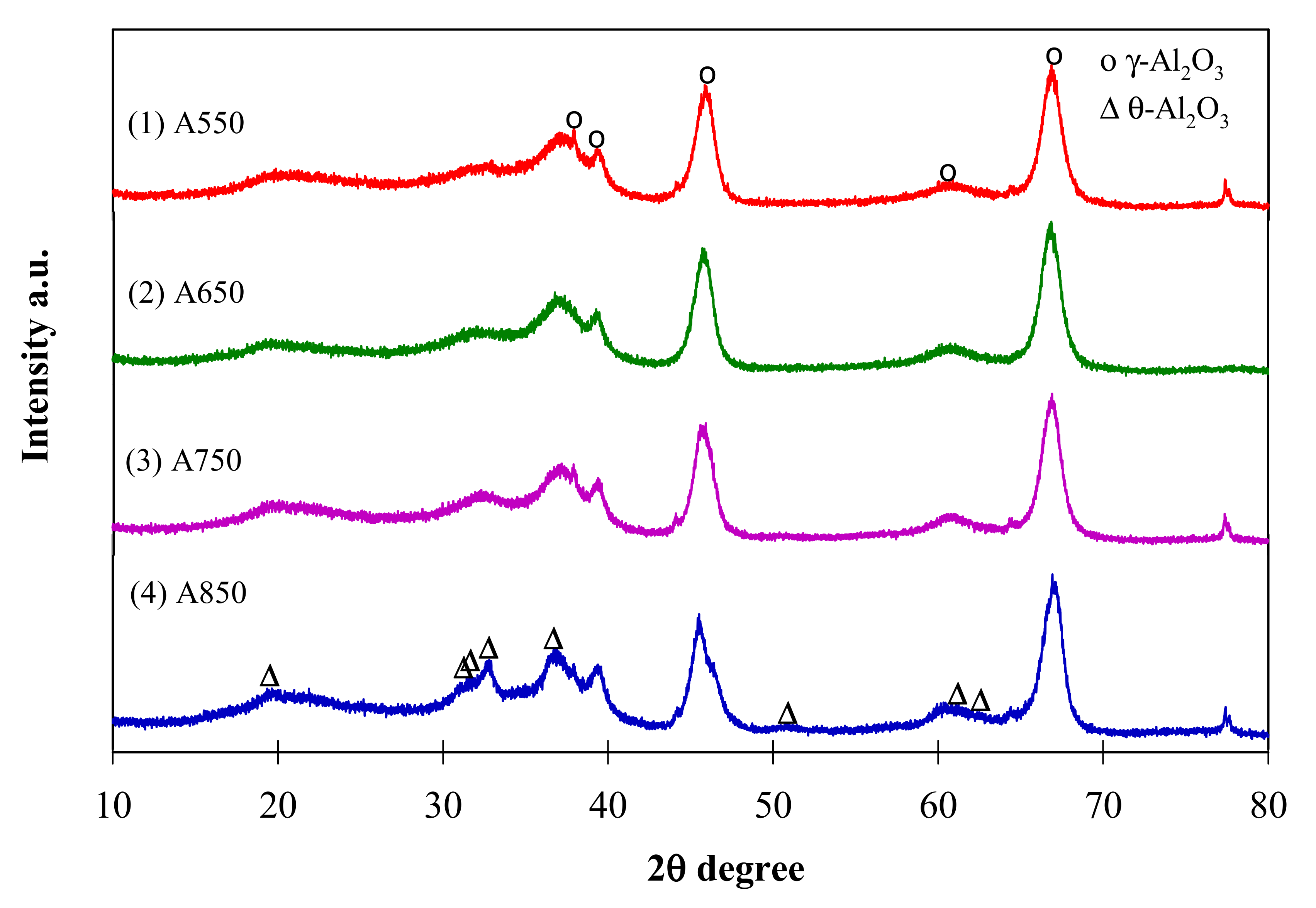
Figure 4.
XRD patterns of spent γ-Al2O calcined at different temperatures.
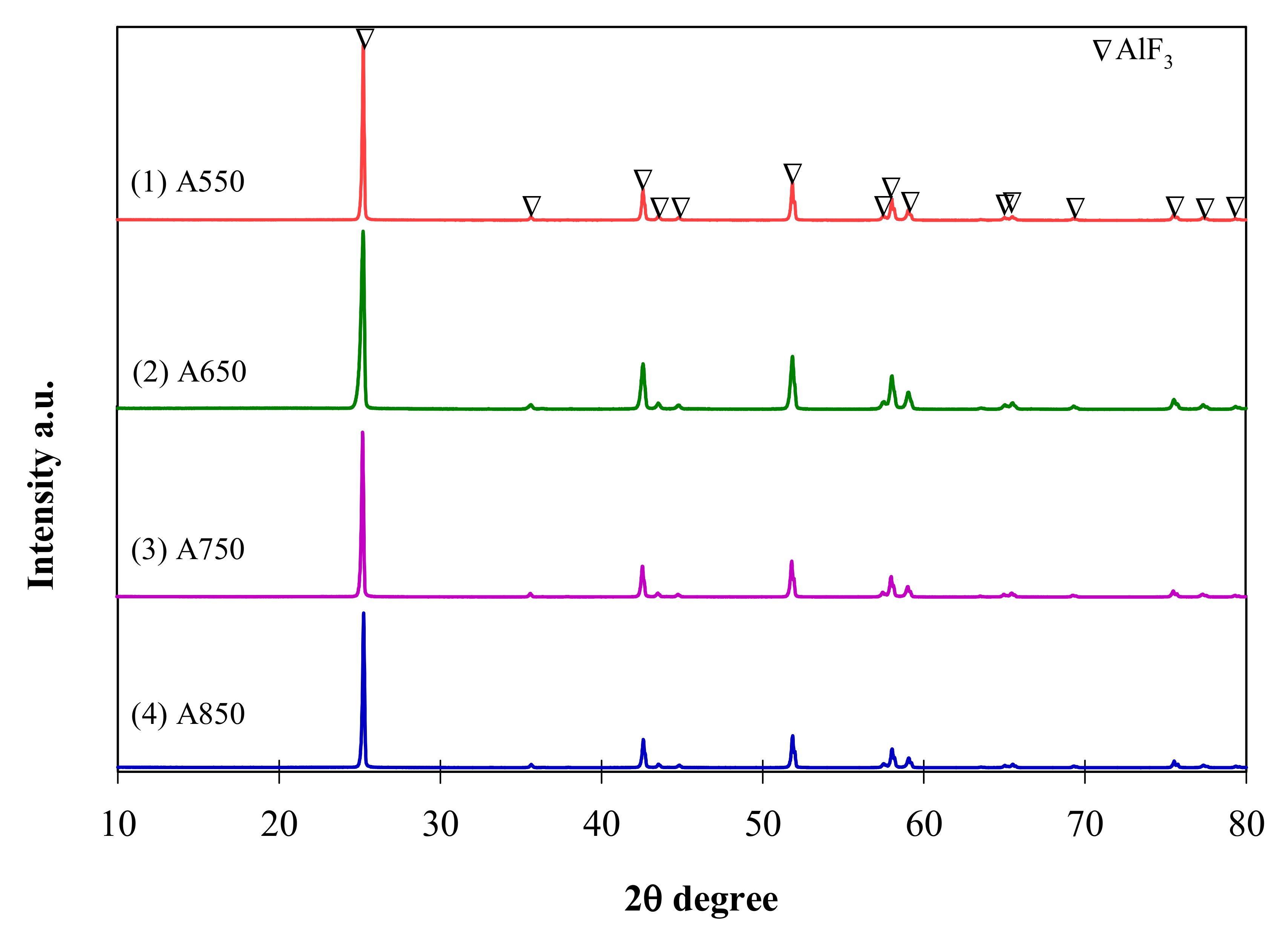
Figure 5.
NH3-TPD deconvolution curves of γ-Al2O3 obtained at different calcination temperatures.

Figure 6.
Linear relationship between TrFE formation and weak acidic sites.


Table 1.
The NH3-TPD analysis depicting the acidic sites and coke amount in each catalyst.
| Catalyst | Amount of Acidic Sites (mmol-NH3/g-Catalyst) | Coke (%) | ||||
|---|---|---|---|---|---|---|
| Weak | Moderate | Strong | Total | (Weak + Moderate)/Strong | ||
| A550 | 0.246 | 0.256 | 0.445 | 0.947 | 1.127 | 12.40 |
| A650 | 0.217 | 0.297 | 0.343 | 0.857 | 1.498 | 11.78 |
| A750 | 0.280 | 0.282 | 0.300 | 0.862 | 1.878 | 11.47 |
| A850 | 0.255 | 0.263 | 0.453 | 0.971 | 1.144 | 13.97 |
Table 2.
Surface area and pore volume of each catalyst.
| Catalyst | Surface Area (m2 g−1) | Pore Volume (cm3 g−1) |
|---|---|---|
| A550 | 141.2 ± 0.3 | 0.821 |
| A650 | 140.8 ± 0.3 | 0.847 |
| A750 | 130.5 ± 0.3 | 0.758 |
| A850 | 119.8 ± 0.3 | 0.817 |
Publisher’s Note: MDPI stays neutral with regard to jurisdictional claims in published maps and institutional affiliations. |
© 2021 by the authors. Licensee MDPI, Basel, Switzerland. This article is an open access article distributed under the terms and conditions of the Creative Commons Attribution (CC BY) license (https://creativecommons.org/licenses/by/4.0/).
Share and Cite
MDPI and ACS Style
Sheraz, M.; Anus, A.; Thi Le, V.C.; Andrew Swamidoss, C.M.; Kim, S. The Effect of Catalyst Calcination Temperature on Catalytic Decomposition of HFC-134a over γ-Al2O3. Catalysts 2021, 11, 1021. https://doi.org/10.3390/catal11091021
AMA Style
Sheraz M, Anus A, Thi Le VC, Andrew Swamidoss CM, Kim S. The Effect of Catalyst Calcination Temperature on Catalytic Decomposition of HFC-134a over γ-Al2O3. Catalysts. 2021; 11(9):1021. https://doi.org/10.3390/catal11091021
Chicago/Turabian StyleSheraz, Mahshab, Ali Anus, Van Cam Thi Le, Caroline Mercy Andrew Swamidoss, and Seungdo Kim. 2021. "The Effect of Catalyst Calcination Temperature on Catalytic Decomposition of HFC-134a over γ-Al2O3" Catalysts 11, no. 9: 1021. https://doi.org/10.3390/catal11091021
Note that from the first issue of 2016, this journal uses article numbers instead of page numbers. See further details here.