

Self-Standing Hierarchical Porous Nickel-Iron Phosphide/Nickel Foam for Long-Term Overall Water Splitting
School of Materials Science and Engineering, Shanghai Jiao Tong University, 800 Dongchuan Road, Shanghai 200240, China
*
Authors to whom correspondence should be addressed.
Catalysts 2023, 13(9), 1242; https://doi.org/10.3390/catal13091242
Submission received: 14 July 2023
/
Revised: 15 August 2023
/
Accepted: 24 August 2023
/
Published: 26 August 2023
(This article belongs to the Topic Synthesis, Characterization and Performance of Materials for a Sustainable Future, 2nd Volume)
Abstract
:Electrolytic water splitting is a promising path for the production of clean hydrogen when combined with green electric power, such as photovoltaic and wind power; however, the high current water electrolysis is mainly dependent on the utilization of Pt, Ru, and other expensive materials, while the transition metal-based catalysts still need improvement in electrocatalytic activity and stability. Here, we present the preparation of economic and scalable electrode materials, Nickel-Iron phosphide/Nickel foam (NiFeP/NF), with a hierarchical porous structure for overall water splitting as both the anode and cathode. An overall potential of 1.85 V for the current density of 100 mA cm−2, and a long lifetime of 700 h, were achieved by using NiFeP/NF as both the anode and cathode. The nanostructures of the composite phosphides were investigated and the spent electrode after long-term electrolysis was characterized to investigate the long-term failure mechanism of the phosphides. Surface shedding and reconstruction theories were proposed for the failure of the NiFeP/NF cathode and anode in long-term electrolysis, respectively. Furthermore, TiO2 coating was proved to be an efficient strategy to elongate the lifetime of the phosphide electrodes, which shows a slow current decline rate of 0.49 mA·cm−2 h−1.
1. Introduction
The energy crisis, environmental pollution, and population explosion make it essential to develop clean and renewable energy-related materials and technologies. Among various new energy sources, photovoltaic and wind power have lower requirements on geographical conditions and can be promoted in many places in the country. Due to the power fluctuation in solar and wind power, efficient energy storage methods are needed to store the energy at the peak of power generation. Electrolytic aqua hydrogen converts electric energy into hydrogen energy; an amount of 1 kg of hydrogen can store 1.4 × 10⁵ kJ of energy. The energy density is 130 times higher than that of lithium-ion batteries, showing obvious advantages in energy storage. In addition, when pure hydrogen is consumed, it will not emit carbon dioxide and various toxic and harmful waste gases like fossil fuel combustion; therefore, the promotion of hydrogen energy is very conducive to the improvement of the environment [1,2].
The dominant hydrogen in the market is mainly from fossil fuel conversion, which accounts for ~95% of today’s hydrogen production. A variety of green hydrogen production methods gradually emerged. The water electrolytic device structure is relatively simple, including electrolytic cells, electrodes, collector plates, and a separated membrane [1], whereas noble metal catalysts are commonly used in commercial electrolytic devices. To lower the cost of the electrolytic strategy, non-precious metal-based electrodes are intensively invested in. A lot of progress has been made in electrode materials and device designs [2]. Hydrogen production using electrolytic water splitting has great potential, especially in combination with the increasing scale of renewable energy power generation.
As the core component of a water electrolytic device, the electrode determines the reaction rate, efficiency, and lifetime of the device. The evaluation of electrode performance usually includes two aspects: the electrocatalytic activity, and stability. The electrocatalytic activity is related to the energy efficiency and hydrogen yield, for which as much current density as possible is to be produced under a certain bias. Stability, especially the ability to maintain good electrocatalytic activity for a long time, is the key to reducing material and maintenance costs [1,3].
An electrode consists of the conducting substrate and the electrocatalytic material on the surface. The substrate material conducts the current from the power source to the electrode surface, so the resistance of the substrate must be minimized to prevent waste of energy. Considering the chemical corrosion in the strong alkali electrolyte and the electrochemical corrosion during electrolysis, the most commonly used substrates are carbon materials and corrosion-resistant metals, such as carbon paper [1,2], carbon cloth [3,4], nickel [5], stainless steel [6,7], titanium [8], and so on. In addition, in order to increase the active area of the electrode surface, the substrate can be processed for surface nanostructures. For example, carbon paper was first loaded with carbon tubes and then impregnated with cobalt sulfide, which greatly increased the specific surface area of the electrode and significantly increased the electrocatalytic activity [9]. Raney nickel was loaded on the surface of nickel mesh as the cathode for enhanced surface areas of active nickel catalyst [10]. Materials with large specific surface areas can also be directly used as substrates, such as copper foam [11], nickel foam [12], etc.
Electrocatalytic material plays a key role in the electrolysis. Since the reaction mechanisms of the anode and cathode are very different, electrocatalytic materials are only suitable for either Hydrogen evolution reactions (HERs) or Oxygen evolution reactions (OERs). The electrocatalytic materials can be roughly divided into noble-metal-based and non-noble-metal-based materials. Noble-metal-based materials are the most widely used electrocatalytic materials. Pt has very low HER overpotential and strong corrosion resistance, becoming the most commonly used electrocatalytic material for HERs. Ru and Ir, as well as their oxides, are widely used as electrocatalytic materials for OERs [13,14]. Since noble-metal-based materials are expensive, rare, and popular in many other chemical industries, the development of non-noble-metal-based materials has received intensive attention. The non-noble-metal-based electrolytic materials include transition metals and their alloys [15], transition metal oxides [16], transition metal sulfides [17], transition metal phosphides, etc.
Transition metal phosphides (TMP) generally have good electrical conductivity, a large number of highly active sites on their surface, and a variety of compounds and morphologies; thus, they have become a popular group of electrocatalytic and photocatalytic materials. The electrocatalytic properties of TMPs, including copper phosphide (Cu3P) [18,19,20], nickel phosphide (Ni2P, Ni5P4, etc.) [21,22], and cobalt phosphide (CoP, Co2P, CoP2) [23,24] for HERs and OERs have been investigated. These TMPs consist of a single transition metal element and exhibit excellent activity and stability; however, there is still room for improvement in the water-splitting performances of TMPs. The interaction of TMP with the intermediate hydrogen product is reflected by the adsorption energy of hydrogen (ΔGH*), and this effect has certain rules: Some TMP values of ΔGH* are negative (such as phosphates of Cu and Fe), and some TMP values of ΔGH* are positive (such as phosphates of Ni, Co, and Mn). When two TMPs with opposite values of ΔGH* are combined, the ΔGH* will shift toward zero, thus improving the HER activity [25,26,27,28].
It is generally believed that the OER active site of TMP is not phosphide itself but phosphates, hydroxides, or hydroxyl oxides generated by the oxidation of phosphides under a positive potential [29,30] on the surface of phosphides. Among them, bimetallic hydroxides or hydroxyl oxides, especially NiOOH/FeOOH, have been considered very active electrocatalysts for OERs [31,32]; however, using phosphides as OER catalysts can bring about positive effects on charge transfer, surface area, and electronic structures, which lead to better performance than their hydroxyl oxide counterparts [33]. For example, the active sites of the Ni1−xFex-P/PO3@fCNTs OER electrocatalyst were ascribed to Fe-doped γ-NiOOH, and the Fe ratio can affect the selectivity of Ni1−xFex-P/PO3@fCNTs [34]. Nickel-Iron phosphide has been proven to be a highly active and stable electrocatalyst for both HERs and OERs and is often considered to be an overall water-splitting electrocatalyst [12,35,36].
TiO2 is stable in both basic and acidic solutions, so it can be coated onto electrodes to improve their electrochemical or photoelectrochemical stability [37,38,39]. Various methods, such as spin coating [40], atom layer deposition [41], and magnetron sputtering [42] have been utilized to coat the TiO2 on the surface of substrates.
TMPs as electrocatalytic materials have been intensively investigated for their outstanding performance in water splitting. Most of the reports concern the performance of the TMP electrode as either the cathode or anode. There are few reports about the direct application of TMP electrodes in long-term electrolysis in a two-electrode configuration. Herein, we present a scalable preparation of Nickel-Iron phosphide/Nickel foam (NiFeP/NF) as both the anode and cathode for long-term electrolysis. The surface morphology of the as-prepared NiFeP/NF was observed, which shows the Ni5P4 nanosheets with Fe2P nanoparticles attached. The phosphorization degree and Fe content were optimized. The two-electrode electrolysis, based on NiFeP/NF, shows excellent HER and OER properties. The long-term spent electrodes on the anode and cathode were characterized to investigate the probable mechanism for the performance declination after long-term electrolysis. Based on the failure mechanism, a facile strategy of surface coating using TiO2 on NiFeP/NF has been proposed and shown significantly improved stability.
2. Results and Discussion
2.1. Preparation and Water-Splitting Performance of NiFeP/NF
The preparation process of NiFeP/NF is schematically shown in Figure 1. The Nickel’s surface tends to form a dense oxide film, which is also the source of its corrosion resistance. Soaking in HCl can corrode the oxide film on the surface to a certain extent, so as to create conditions for subsequent processes. When nickel is immersed in water, its surface is slowly corroded by water and dissolved oxygen, and a large number of nanosheets are formed on the surface of the nickel substrate. After immersion in Fe(NO3)3 solution, Ni can be further oxidized using Fe3+ and generates the composite structure of Ni(OH)2/Fe(OH)2. In the phosphorization process, NaH2PO2·H2O begins to decompose at 280 °C (Equation (1)), producing phosphine gas (PH3) and sodium hydrogen phosphate (Na2HPO4). The PH3 can react with metal hydroxides and metal elemental substances to produce metal phosphides with a variable stoichiometric ratio. Because nickel itself is not easily corroded by PH3 to large depths, only the thin layer of nickel on the surface could be converted into nickel phosphide. This preparation method avoids the use of expensive noble metals or other expensive reagents, as well as the fluorides that were commonly used in other methods for TMP materials.
2NaH2PO2 = PH3(g) + Na2HPO4
Many clusters of nanosheets, with a thickness of ~600 nm, are coated on the surface of NiFeP/NF, as shown in the high-magnification SEM image in Figure 2a. These nanosheets cover the whole surface of NF with a homogeneous distribution, as shown in Figure 2b. Figure 2c–e are TEM images of NiFeP/NF after being prepared using the FIB method with the surface protection of a carbon layer. A hierarchical porous structure of NiFeP/NF is observed, as shown in Figure 2c. Besides the uniform gray part on the upper part of the graph, which is the carbon film plated on the surface during sample preparation, mesoporous NiFeP nanosheets were observed, indicating a high electrocatalytic surface area. Under the NiFeP nanosheets is a thin layer of nickel phosphide supporting the surface NiFeP nanosheets. Between the surface phosphide and the metal substrate, there is a macroporous structure, which is probably formed during the phosphorization process. The bottom part, with obvious large and dense grains, is metal Ni. Connections are still present between the substrate and the surface nanosheets. It is obvious that the phosphating process erodes a thickness of ~2 um on the surface.
The TEM image in Figure 2d shows the structure of the surface nanosheets, which are made up of nanoparticles with a size smaller than 10 nm. The HR-TEM Figure 2e is of the red box area in Figure 2d, showing the atomic lattice. The lattices with a spacing of 0.215 nm and 0.221 nm, and an angle of 82.1°, correspond to the (121) and (210) crystal planes of Ni5P4, respectively. In the deep contrast area, the lattice spacing of 0.198 nm and 0.145 nm, at an angle of 83.63°, correspond to the (210) and (013) of Fe2P, respectively. The close contact of these two phases indicates that a heterojunction of Ni5P4 and Fe2P has formed. The XRD of NiFeP/NF, Figure 2f, confirms the presence of Ni5P4 and Fe2P. Besides the major phase of Ni, another two phases of Ni5P4 and Fe2P can be detected in NiFeP/NF.
EDS of the cross-section of the NiFeP/NF is performed to analyze the element distribution of NiFeP/NF. In Figure 3a, the upper half is nanosheets, and the bottom half is the Ni base. In Figure 3b, Ni is evenly distributed on both sides, suggesting that it is the major element in the nanosheets and the foam substrate. Most Fe only infiltrated the nanosheets, and just a small amount of Fe diffused into the Ni base, as shown in Figure 3c. In Figure 3d, P only exists in the nanosheets, which leaves the Ni base uncorroded and maintains the mechanical strength of the NF.
The phosphorizing degree of TMP has a significant impact on its electrocatalytic performance. Generally, when P content increases, electrical resistance increases, and so does its activity [23]; therefore, it is necessary to find the appropriate phosphating degree for the TMP electrocatalytic material. In addition, the phosphating temperature also has a great impact on the mechanical properties of the material. In this work, sodium hypophosphate dosage plays a key role in the control of the phosphating degree of the TMP electrodes by adjusting the concentration of PH3 in the furnace. The LSV voltammetry curves, as pictured in Figure 4a, were obtained by using the LSV method in a three-electrode system. The sample prepared with 0.5 g sodium hypophosphate showed the best performance for hydrogen and oxygen evolution electrolysis. The EIS method was used to analyze the impedance of some samples in a two-electrode system. The results are shown in Figure 4b. The impedance of the electrode can be calculated from the radius of the circular arc in the Nyquist curve. Obviously, with the increase in the amount of sodium hypophosphate, the resistance of the electrode also increased gradually from 1.5 to 3 Ω. The increased resistance was not only due to the increase in resistivity caused by the increase in P content in TMP but probably due to the increased thickness of the phosphide layer. After increasing the amount of sodium hypophosphate, as shown in Figure 4c, the brittleness of the material increased significantly. It is more likely to crack when the samples are over-phosphorized (Figure 2c). The surface phosphide was easy to break when cutting or preparing the electrodes, which made it difficult to apply in electrocatalysis.
The metal ratio of bimetallic phosphide has a significant impact on its electrocatalytic activity [25,26,27,28,29]. It is generally believed that the electrocatalytic performance of the phosphide can be improved by the formation of a compound of two transition metals, and the ratio of the two transition metals in the material composition should be a certain intermediate value. In this work, the Ni(OH)2 precursor was immersed in Fe(NO3)3 solution to achieve iron doping, and the Fe content in the material could be adjusted by adjusting the concentration of Fe(NO3)3 solution. Figure 4d shows the LSV curves of the hydrogen and oxygen evolution of NiFeP samples prepared by soaking in Fe(NO3)3 solutions with different concentrations. It is obvious that the sample prepared with 0.1 M Fe(NO3)3 solution has the highest activity. According to the theory of the influence of bimetallic phosphides on the adsorption energy of reactants, the adsorption energy of H on the two metal phosphates is positive and negative, respectively [26]. The adsorption energy of the composite material is, thus, in between their adsorption energy, probably in proportion to the ratio. Among the tested endmembers, the optimal concentration of Fe(NO3)3 solution is 0.1 M. The approximate ratio of Fe and Ni in the phosphide is ~0.4 from the XPS analysis on the surface, which will be discussed in the following section.
The as-prepared NiFeP/NF has outstanding electrocatalytic hydrogen and oxygen evolution performance and can be used as both the anode and cathode in the water electrolytic device at the same time. In a two-electrode system with the same 5 mm × 5 mm NiFeP/NF electrodes for both the cathode and anode in 1 M KOH, the water was electrolyzed continuously for 700 h at a current density of 100 mA/cm2, and the electrolyte was replaced once. Before and after the CP test, the LSV curves of the NiFeP/NF cathode and anode, together with pristine NF and commercial Pt/C, RuO2, were tested using a three-electrode system, and the results are shown in Figure 5a–d. In the HER reaction, Figure 5a, NiFeP/NF has a higher onset overpotential (140 mV) at 10 mA/cm2 compared to that of Pt/C (21 mV); however, NiFeP/NF’s current density exceeds that of Pt/C at 0.42 V due to its faster growth of current density with increased bias. After 700 h of reaction, the activity of NiFeP/NF decreased but it is still higher than that of pristine NF. HER Tafel slopes of the samples were calculated and are presented in Figure 5b. The Tafel slope of NiFeP/NF is 49 mV/dec, slightly higher than that of Pt/C, indicating that the activity of NiFeP/NF is only slightly lower than that of Pt/C. The major reason for the better high-current performance of NiFeP/NF is its large specific surface area. Concerning the OER activity of NiFeP/NF, Figure 5c shows a much better performance than RuO2, and maintained a relatively high activity after 700 h of reaction. Figure 5d leads to the same conclusion that NiFeP/NF has excellent OER activity and stability. The potentials needed for 100 mA/cm2 for a two-electrode system with NiFeP/NF is 1.8 V, lower than those with NF (2.18 V) or the Pt/C-RuO2 pair (1.975 V). The potential curve of NiFeP/NF in the constant current test of 100 mA/cm2 is shown in Figure 5e. The initial potential was about 1.9 V, which was not much different from the required potential of 1.8 V at the current density of 100 mA/cm2 measured in the LSV curve. With the extension of the reaction time, the potential required for electrolytic water also increases gradually up to 2.3 V. Newly prepared KOH electrolyte was refilled at 450 h. Due to this interference, the potential was reduced to 1.9 V, and then gradually increased. The energy efficiency of water electrolysis can be obtained by dividing the theoretical potential of 1.23 V by the actual potential. The initial efficiency of the 700 h durability test was 65%, and the minimum efficiency was 53%. Even after a long time of use, the energy efficiency could still meet the needs of production.
2.2. Analysis of NiFeP/NF after Long-Term Electrolysis and Improvement with TiO2 Coating
For industrial applications, it takes a lot of manpower and material resources to replace the failed electrode each time, especially when the electrolyte is strongly acidic or strongly alkaline; therefore, the stability issue in industry is very important, which is closely related to the running cost. Unfortunately, there are very few studies on the long-term stability of TMPs. In this work, the structural changes of NiFeP/NF were studied and an improvement scheme was tentatively proposed using TiO2 as a corrosion-resistance coating.
The morphology changes in the electrode surface before and after the water electrolysis reaction for 200 h were studied mainly by SEM observations. The surface morphology of the as-prepared NiFeP/NF shows nanosheet structures well-distributed on the surface, as pictured in Figure 6a. After anodic OER for 200 h, obvious surface reconstruction was observed and finer nanosheets were produced, as shown in Figure 6b. This can be ascribed to the anodic oxidation of the TMP in an alkaline environment into metal hydroxyl oxides, the morphology of which is iconic nanosheet structures. After working as the cathode for the HER for 200 h, as shown in Figure 6c, part of the electrode surface fell off, exposing the underneath Nickel phosphide layer with lower activity.
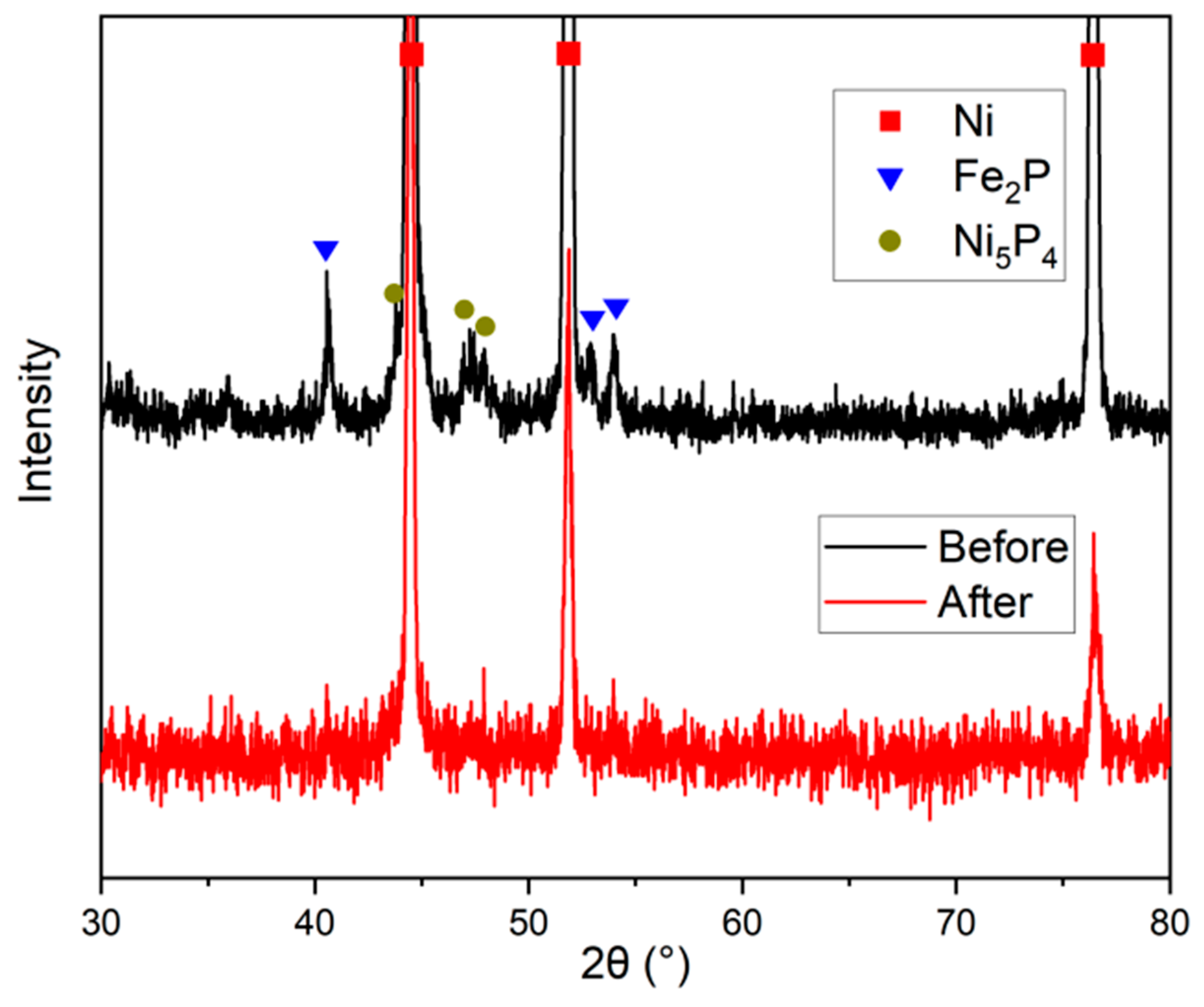
The surface of the NiFeP/NF cathode before and after use was further studied by XRD, shown in Figure 7. The diffraction peaks of the Ni5P4 and Fe2P phases could not be observed after 200 h, indicating that the two phosphide compounds were both transformed. Since the volume of hydrogen is twice that of oxygen, the electrocatalytic particles on the surface of the cathode for the HER are more strongly impacted by the bubbles. The bubbles, especially from the inner gaps, are more likely to gather into large bubbles and destroy the surface structure.
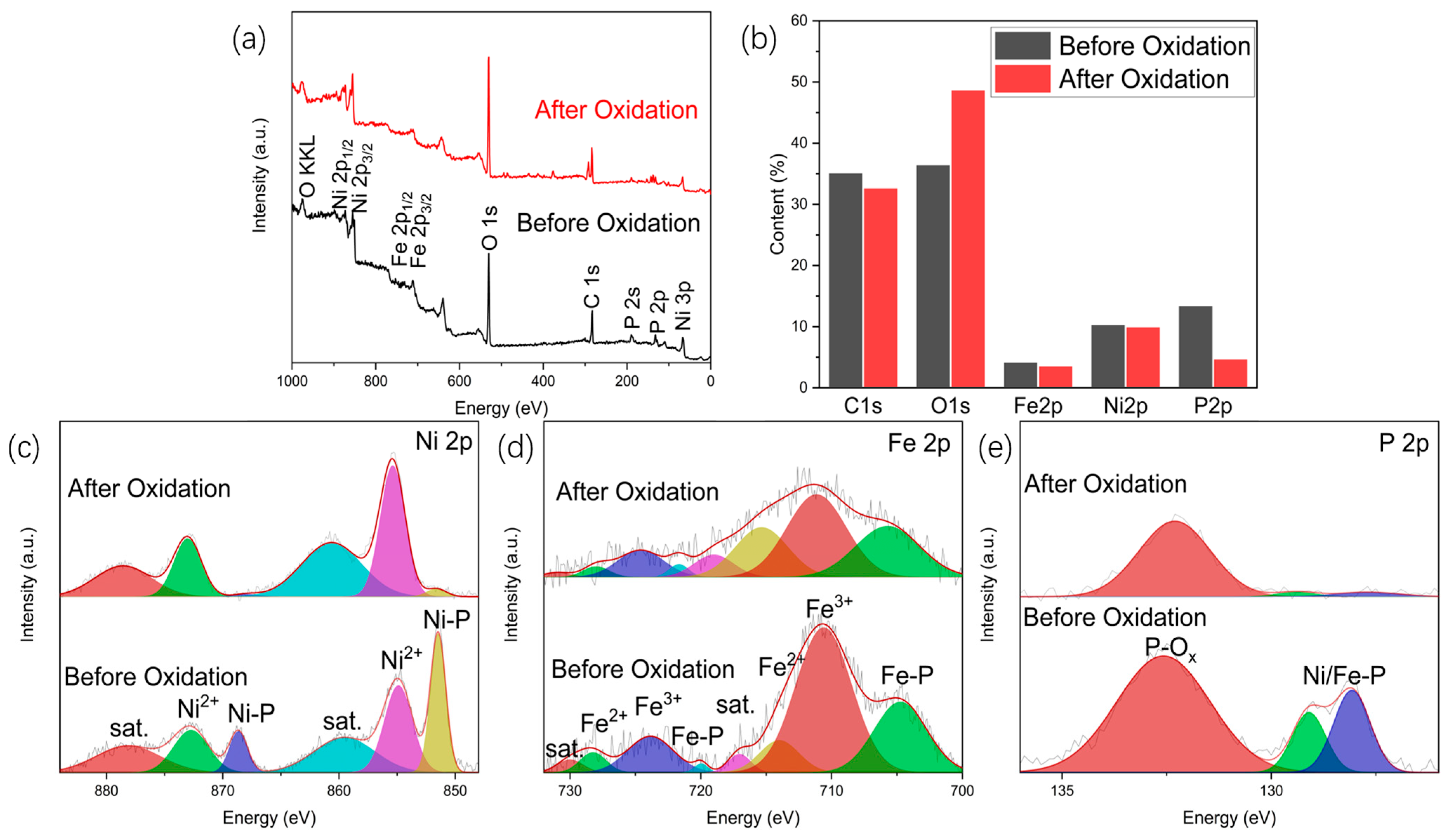
The cathode surface materials are, therefore, more prone to be shredded off. The surface of the NiFeP/NF anode after long-term reaction was further investigated by XPS. The pristine NiFeP/NF (before oxidation) and spent NiFeP/NF (after oxidation for 200 h) were characterized and compared in Figure 8a. The comparison of the relative content of Ni/Fe, Figure 8b, shows only a slight decrease in Fe after 200 h. This indicates a very slight change in the transition metal elements on the surface and almost no shedding from the surface. The high-resolution spectrum of Ni 2p of the pristine sample in Figure 8c shows that, in addition to nickel phosphide, some Ni2+ do not combine with P on the surface of the material, which should be the hydroxyl oxides and oxides of Ni. The overall binding energy of Ni increased after oxidation. This indicates that nickel phosphide was oxidized after long-term anodic catalysis. The high-resolution spectrograph of Fe 2p, presented in Figure 8d, shows a similar oxidation of iron phosphide. The high-resolution spectrum of P 2p is presented in Figure 8e. Before oxidation, P existed in the form of both metal phosphide and phosphorus oxide, while after oxidation, the metal phosphide on the surface almost disappeared, and the relative content of phosphorus also decreased significantly. It is speculated that in the process of oxygen evolution, metal phosphide was transformed into metal phosphate and hydroxyl oxide, and other species, and as the reaction progressed, phosphorus was lost from the surface. In summary, the failure form of the NiFeP/NF anode is mainly the surface reconstruction caused by the oxidation of phosphides to other species such as phosphates and hydroxyl oxides.
Based on the change in surface structure of the NiFeP/NF electrodes as both the anode and cathode, a surface coating with TiO2 was proposed to elevate the shedding and oxidation of the surface phosphide. The surface morphology of the as-prepared NiFeP-TiO2/NF is shown in Figure 9a. TiO2 can be observed on the surface of the material as a network. After the material was used as the anode for water electrolysis for 200 h, as shown in Figure 9b, some cracks occurred on the surface. Even though the oxidation of phosphide into hydroxyl oxide still occurred, the overall condition remained relatively good. After the material was used as the cathode for water electrolysis for 200 h, as shown in Figure 9c, part of the surface shed, while the surface of the remaining part kept some original nanostructures.
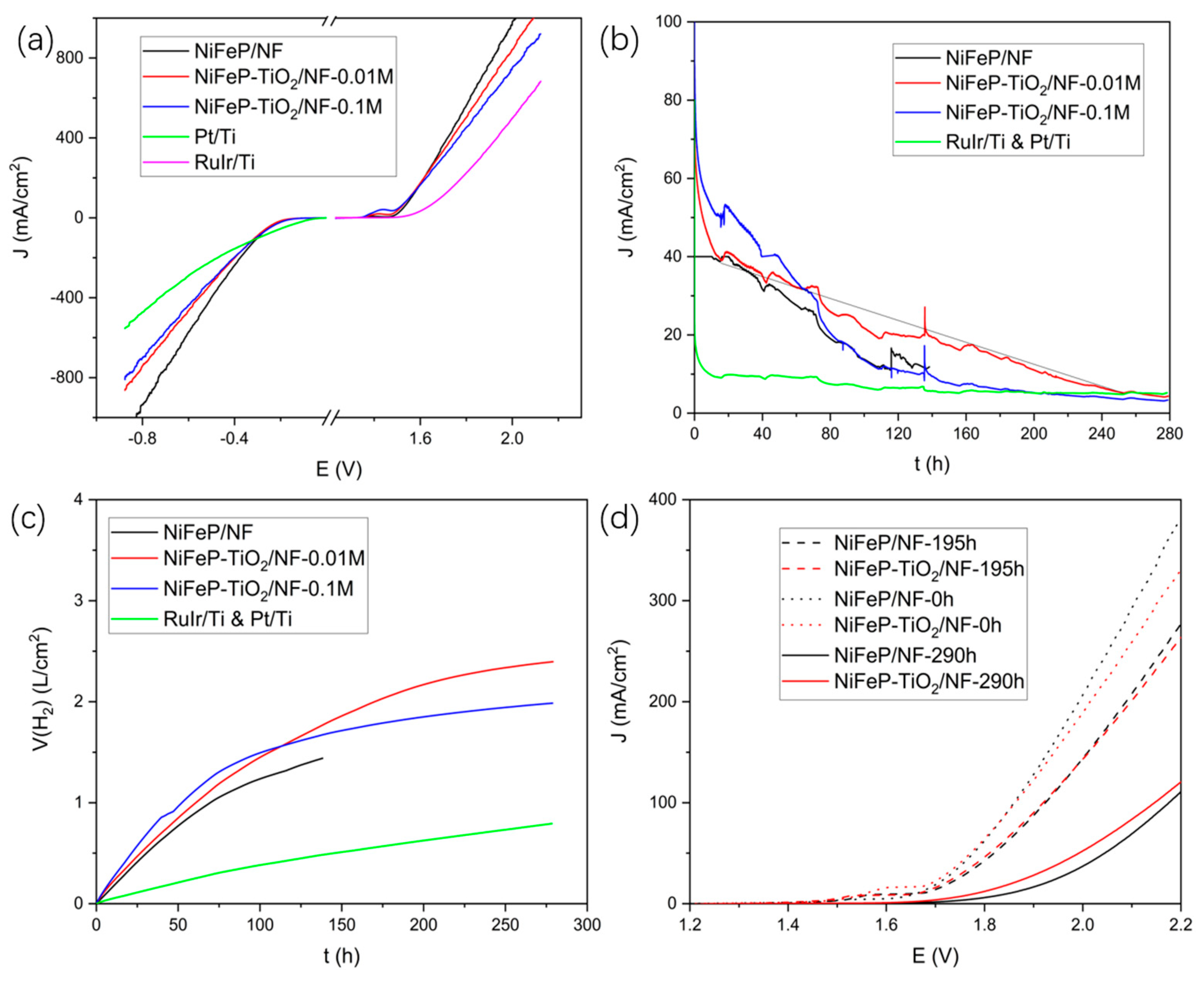
NiFeP-TiO2/NF-0.01 M and NiFeP-TiO2/NF-0.1 M samples were obtained by treating the materials with 0.01 M and 0.1 M TiCl4 methanol solution, and NiFeP/NF without TiCl4 methanol solution was used as the control for comparison of the activity and stability in electrolytic water splitting. Figure 10a shows the LSV curve of each sample. The hydrogen evolution and oxygen evolution activities of the material decreased slightly after the coating of TiO2, mainly due to the blockage of a small amount of the active sites by the TiO2 layer, however, they were still higher than the noble metal electrodes. Figure 10b shows the current curve of each sample measured at a constant potential of 1.8 V. It is obvious that NiFeP-TiO2/NF-0.01 M had the slowest current decline rate, which is about 0.49 mA·cm−2 h−1, showing the best stability. By integrating the current over time, the total amount of charge passing through the electrode can be obtained. The Faraday efficiency of a HER is approximately 100% and the total amount of hydrogen produced over time can be calculated, as shown in Figure 10c. NiFeP-TiO2/NF-0.01 M lagged behind in hydrogen production due to the relatively smaller current in the early stage; however, it maintained a large current after a long reaction time and produced the most hydrogen after 120 h. Therefore, the NiFeP-TiO2/NF-0.01 M (hereinafter referred to as NiFeP-TiO2/NF) is the most stable electrode prepared in this paper. Figure 10d is a comparison of the LSV curves of NiFeP/NF and NiFeP-TiO2/NF after continuous electrolyzation at a 1.8 V constant potential for a period of time. It can be seen that the performance of NiFeP/NF was slightly better than NiFeP-TiO2/NF in the beginning; however, at 195 h, the gap between the two became very small, and at 290 h, the performance of NiFeP-TiO2/NF became higher than that of NiFeP/NF. This proves that TiO2 support is indeed beneficial to improving the electrolytic water stability of NiFeP-TiO2/NF.
In conclusion, the NiFeP/NF shows outstanding electrocatalytic performance in water-splitting electrocatalysis. The phosphide electrode can be used as the anode and cathode at the same time in a two-electrode cell for 700 h. The performance declination is still observed and can be ascribed to the surface shedding on the cathode and oxidation on the anode. Surface coating using TiO2, even though not the best strategy, is observed to effectively elevate the activity declination.
3. Experiment Materials
NF was purchased from Guangjiayuan New Materials (Kunshan, China), with an area density of 380 g/m2 and thickness of 1 mm. Chemicals, including Pt/C, RuO2, HCl, Fe (NO3)3·9H2O, KOH, C2H6O, and CH3OH were purchased from Sinopharm Chemical Reagent Co., Ltd. (Shanghai, China); TiCl4 and NaH2PO2·H2O were purchased from Shanghai Aladdin Biochemical Technology Co., Ltd. (Shanghai, China); Nafion 117 solution (5%) was purchased from Sigma-Aldrich (St. Louis, MO, USA); Ar was purchased from Air Liquide Co., Ltd. (Shanghai, China). Ultrapure water was produced using a Milli-Q ultrapure water system, the system was purchased from Merck (Rahway, NJ, USA).
3.1. Preparation of NiFe Hydroxide/NF Precursor
First, a nickel foam with a thickness of 1 mm and an appropriate size was cut and ultrasonically cleaned with ethanol and pure water for 15 min, respectively, to remove the oil and dust. Then, the cleaned nickel foam was immersed in 3 M HCl and soaked at room temperature for 1.5 h. After washing with plenty of water, the foam was immersed in ultrapure water for 24 h to form nanosheet morphology, and then immersed in 0.1 M Fe (NO3)3 solution for 1 h for ion exchange. Finally, the samples were taken out and dried at 60 °C.
For comparison, the concentration of Fe (NO3)3 solution was adjusted to 0.05 M and 0.2 M. Other conditions remained unchanged, and two groups of samples were prepared.
3.2. Preparation of NiFeP/NF
Appropriate dosage of NaH2PO2·H2O was weighed according to the volume of tube furnace. Every 1 cm3 of the tube space corresponded to 2 mg NaH2PO2·H2O. The volume of tube furnace used in this paper was 251.2 cm3, therefore, 500 mg NaH2PO2·H2O was used. NaH2PO2·H2O was put into a porcelain boat, the top of which was capped to prevent spilling the chemical. The porcelain boat was placed upstream of the gas flow, and the sample was placed downstream. After the furnace tube was sealed, the vacuum was pumped and argon was filled successively. The process was repeated three times to empty the air in the furnace tube. The furnace was heated at a heating rate of 2 °C/min, kept at 350 °C for 2 h, and then cooled to room temperature naturally. Argon gas was kept flowing at 70 sccm during the process. After the heat treatment, the sample was taken out and marked as nickel-iron bimetallic phosphide/nickel foam (NiFeP/NF).
For comparison, the dosage of NaH2PO2·H2O was adjusted to 100, 200, 300, 400, 600 mg, and other conditions remained unchanged. Another 5 groups of samples were prepared.
3.3. Preparation of NiFeP-TiO2/NF
First, 0.01 M TiCl4 methanol solution was prepared in a fume hood. NiFeP/NF was immersed into TiCl4 methanol solution and stirred for 5 s to ensure the solution fully infiltrated its surface. Then, the sample was taken out and exposed to the air for natural drying. After 1 h, TiCl4 was naturally hydrolyzed into TiO2 to prepare NiFeP-TiO2/NF.
For comparison, 0.1 M TiCl4 methanol solution was prepared to treat the material, other conditions remained unchanged.
3.4. Preparation of Electrode
The sample was cut as required: an L shape formed by a square of 5 mm × 5 mm and a rectangle tap of 5 mm × 2.5 mm. The tap was polished until the nickel base was exposed, and then a wire was connected to the polished area with soldering tin. Finally, the whole tap was encapsulated with epoxy resin.
For comparison, 40 mg Pt/C or RuO2, 45 μL Nafion, 405 μL ethanol, and 300 μL water were evenly mixed with ultrasonication, and 20 μL of the solution was dripped on 5 mm × 5 mm carbon paper and then naturally dried, respectively.
3.5. Characterization
NiFeP/NF, prepared using 0.1 M Fe (NO3)3 and 500 mg NaH2PO2·H2O, as well as NiFeP-TiO2/NF, prepared with 0.1 M TiCl4, were characterized using following methods.
The compositions of the samples were characterized using X-ray diffraction (XRD, ULTIMA IV, Rigaku, Tokyo, Japan) with filtered Cu Kα radiation (λ = 1.5418 Å). The morphologies were characterized using scanning electron microscopy (SEM, GAIA3, TESCAN, Brno, Czech). The microstructures were characterized using high-resolution transmission electron microscopy (HR-TEM, FEI Talos F200X, Thermofisher, Waltham, MA, USA) equipped with energy dispersive spectroscopy (EDS) kit, and the sample was prepared by focused ion beam (FIB, GAIA3, TESCAN, Brno, Czech). Surface compositions and valence states were characterized using X-ray photoelectron spectroscopy (XPS, Thermo Kalpha, Thermo Scientific, Waltham, MA, USA).
3.6. Electrocatalytic Measurements
The electrochemical tests used in this paper include linear sweep voltammetry (LSV), chronopotentiometry (CP), chronoamperometry (CA), and electrochemical impedance spectroscopy (EIS). The electrolyte used in the experiment was 1 M KOH solution, pH = 14, and the test instrument was a multi-channel electrochemical workstation (VMP3, BioLogic, Seyssinet-Pariset, France). The test methods included two-electrode method for CP and CA tests and three-electrode method for LSV and EIS tests. When using two-electrode method, the working electrode and counter electrode were identical electrodes prepared in this work. When using three-electrode method, the working electrode interface was the electrode prepared in this work, the opposite electrode was a platinum wire electrode, and the reference electrode was a Hg/HgO reference electrode. The data for all the potentials reported in this study are vs. RHE. In 1 M KOH, E (RHE) = E (Hg/HgO) + 0.924 V.
4. Conclusions
In this paper, a scalable preparation method of nickel-iron bimetallic phosphide/nickel foam (NiFeP/NF) is presented. The surface of the as-prepared NiFeP/NF showed a nanosheet structure, with Fe2P nanoparticles attached to Ni5P4 nanosheets. The phosphating degree and iron cation dipping conditions were optimized. The prepared NiFeP/NF had excellent hydrogen evolution and oxygen evolution properties, and the potential was 1.85 V when the current density of 100 mA/cm2 was reached. The bimetallic phosphide compound structure shows superior catalytic activity in electrocatalysis to the Pt/Ti and RuIr/Ti control. The NiFeP/NF applied as both the anode and cathode in a two-electrode cell was tested for water electrolysis in an alkaline solution for 700 h.
The activity decline of NiFeP/NF electrodes was analyzed. The surface shedding of the cathode and the surface oxidation of the anode were proposed according to the morphology, XRD, and XPS analysis on the spent sample after 200 h electrolysis. TiO2 coating was applied on the surface of the electrode, which effectively improved the stability of the electrodes.
Author Contributions
Conceptualization, P.Z., F.L. and Q.H.; methodology, Q.H.; validation, Q.H. and H.W.; formal analysis, Q.H.; investigation, Q.H.; resources, P.Z.; data curation, Q.H.; writing—original draft preparation, Q.H.; writing—review and editing, P.Z., J.L., L.Z., F.L. and H.W.; visualization, Q.H. and H.W.; supervision, P.Z. and L.G.; project administration, P.Z.; funding acquisition, P.Z. All authors have read and agreed to the published version of the manuscript.
Funding
This research was funded by National Natural Science Foundation of China (51972210 and 52111530187).
Data Availability Statement
Not available.
Acknowledgments
The authors greatly acknowledge the financial support from the National Natural Science Foundation of China (No. 51972210 and 52111530187). The authors thank the Instrumental Analysis Center of Shanghai Jiao Tong University for access to SEM, TEM, XRD, and XPS.
Conflicts of Interest
The authors declare no conflict of interest.
References
- Chen, Y.; Ren, Z.; Fu, H.; Zhang, X.; Tian, G.; Fu, H. NiSe-Ni0.85Se heterostructure nanoflake arrays on carbon paper as efficient electrocatalysts for overall water splitting. Small 2018, 14, 1800763. [Google Scholar] [CrossRef]
- Zhou, Y.; Xiao, H.; Zhang, S.; Li, Y.; Wang, S.; Wang, Z.; An, C.; Zhang, J. Interlayer expanded lamellar CoSe2 on carbon paper as highly efficient and stable overall water splitting electrodes. Electrochim. Acta 2017, 241, 106–115. [Google Scholar] [CrossRef]
- Wang, P.; Song, F.; Amal, R.; Ng, Y.H.; Hu, X. Efficient water splitting catalyzed by cobalt phosphide-based nanoneedle arrays supported on carbon cloth. ChemSusChem 2016, 9, 472–477. [Google Scholar] [CrossRef]
- Ye, J.; Li, Q.; Ma, X.; Chen, H.; Yuan, T.; Xu, X.; Wang, F. CoNi2S4 nanoparticle on carbon cloth with high mass loading as multifunctional electrode for hybrid supercapacitor and overall water splitting. Appl. Surf. Sci. 2021, 554, 149598. [Google Scholar] [CrossRef]
- Ou, G.; Fan, P.; Zhang, H.; Huang, K.; Yang, C.; Yu, W.; Wei, H.; Zhong, M.; Wu, H.; Li, Y. Large-scale hierarchical oxide nanostructures for high-performance electrocatalytic water splitting. Nano Energy 2017, 35, 207–214. [Google Scholar] [CrossRef]
- Lyu, Y.; Wang, R.; Tao, L.; Zou, Y.; Zhou, H.; Liu, T.; Zhou, Y.; Huo, J.; Zheng, J.; Wang, S. In-situ evolution of active layers on commercial stainless steel for stable water splitting. Appl. Catal. B Environ. 2019, 248, 277–285. [Google Scholar] [CrossRef]
- Schäfer, H.; Sadaf, S.; Walder, L.; Kuepper, K.; Dinklage, S.; Wollschläger, J.; Schneider, L.; Steinhart, M.; Hardege, J.; Daum, D. Stainless steel made to rust: A robust water-splitting catalyst with benchmark characteristics. Energy Environ. Sci. 2015, 8, 2685–2697. [Google Scholar] [CrossRef]
- Pu, Z.; Luo, Y.; Asiri, A.M.; Sun, X. Efficient electrochemical water splitting catalyzed by electrodeposited nickel diselenide nanoparticles based film. ACS Appl. Mater. Interfaces 2016, 8, 4718–4723. [Google Scholar] [CrossRef]
- Wang, J.; Zhong, H.-x.; Wang, Z.-l.; Meng, F.-l.; Zhang, X.-b. Integrated three-dimensional carbon paper/carbon tubes/cobalt-sulfide sheets as an efficient electrode for overall water splitting. ACS Nano 2016, 10, 2342–2348. [Google Scholar] [CrossRef]
- Bernäcker, C.I.; Rauscher, T.; Büttner, T.; Kieback, B.; Röntzsch, L. A powder metallurgy route to produce raney-nickel electrodes for alkaline water electrolysis. J. Electrochem. Soc. 2019, 166, F357. [Google Scholar] [CrossRef]
- Rong, Y.; Ma, Y.; Guo, F.; Qian, J.; Li, H.; Zhou, M.; Xu, Z.; Zheng, Y.-Q.; Li, T.-T. Paintbrush-like Co doped Cu3P grown on Cu foam as an efficient janus electrode for overall water splitting. Int. J. Hydrog. Energy 2019, 44, 28833–28840. [Google Scholar] [CrossRef]
- Ahn, S.H.; Manthiram, A. Direct growth of ternary Ni–Fe–P porous nanorods onto nickel foam as a highly active, robust bi-functional electrocatalyst for overall water splitting. J. Mater. Chem. A 2017, 5, 2496–2503. [Google Scholar] [CrossRef]
- Madhu, R.; Karmakar, A.; Kumaravel, S.; Sankar, S.S.; Bera, K.; Nagappan, S.; Dhandapani, H.N.; Kundu, S. Revealing the pH-universal electrocatalytic activity of Co-doped RuO2 toward the water oxidation reaction. ACS Appl. Mater. Interfaces 2021, 14, 1077–1091. [Google Scholar] [CrossRef] [PubMed]
- Wang, J.; Yang, H.; Li, F.; Li, L.; Wu, J.; Liu, S.; Cheng, T.; Xu, Y.; Shao, Q.; Huang, X. Single-site Pt-doped RuO2 hollow nanospheres with interstitial C for high-performance acidic overall water splitting. Sci. Adv. 2022, 8, eabl9271. [Google Scholar] [CrossRef] [PubMed]
- Hitz, C.; Lasia, A. Experimental study and modeling of impedance of the her on porous Ni electrodes. J. Electroanal. Chem. 2001, 500, 213–222. [Google Scholar] [CrossRef]
- Ahmed, J.; Alhokbany, N.; Ahamad, T.; Alshehri, S.M. Investigation of enhanced electro-catalytic HER/OER performances of copper tungsten oxide@ reduced graphene oxide nanocomposites in alkaline and acidic media. New J. Chem. 2022, 46, 1267–1272. [Google Scholar] [CrossRef]
- Nguyen, D.C.; Doan, T.L.L.; Prabhakaran, S.; Tran, D.T.; Kim, D.H.; Lee, J.H.; Kim, N.H. Hierarchical Co and Nb dual-doped MoS2 nanosheets shelled micro-TiO2 hollow spheres as effective multifunctional electrocatalysts for HER, OER, and ORR. Nano Energy 2021, 82, 105750. [Google Scholar] [CrossRef]
- Downes, C.A.; Libretto, N.J.; Harman-Ware, A.E.; Happs, R.M.; Ruddy, D.A.; Baddour, F.G.; Ferrell Iii, J.R.; Habas, S.E.; Schaidle, J.A. Electrocatalytic CO2 Reduction over Cu3P Nanoparticles Generated via a Molecular Precursor Route. ACS Appl. Energy Mater. 2020, 3, 10435–10446. [Google Scholar] [CrossRef]
- Tian, J.; Liu, Q.; Cheng, N.; Asiri, A.M.; Sun, X. Self-supported Cu3P nanowire arrays as an integrated high-performance three-dimensional cathode for generating hydrogen from water. Angew. Chem. Int. Ed. Engl. 2014, 53, 9577–9581. [Google Scholar] [CrossRef]
- Han, A.; Zhang, H.; Yuan, R.; Ji, H.; Du, P. Crystalline Copper Phosphide Nanosheets as an Efficient Janus Catalyst for Overall Water Splitting. ACS Appl. Mater. Interfaces 2017, 9, 2240–2248. [Google Scholar] [CrossRef]
- Popczun, E.J.; McKone, J.R.; Read, C.G.; Biacchi, A.J.; Wiltrout, A.M.; Lewis, N.S.; Schaak, R.E. Nanostructured nickel phosphide as an electrocatalyst for the hydrogen evolution reaction. J. Am. Chem. Soc. 2013, 13, 9267–9270. [Google Scholar] [CrossRef]
- Wexler, R.B.; Martirez, J.M.P.; Rappe, A.M. Active Role of Phosphorus in the Hydrogen Evolving Activity of Nickel Phosphide (0001) Surfaces. ACS Catal. 2017, 7, 7718–7725. [Google Scholar] [CrossRef]
- Li, H.; Wen, P.; Itanze, D.S.; Kim, M.W.; Adhikari, S.; Lu, C.; Jiang, L.; Qiu, Y.; Geyer, S.M. Phosphorus-Rich Colloidal Cobalt Diphosphide (CoP2) Nanocrystals for Electrochemical and Photoelectrochemical Hydrogen Evolution. Adv. Mater. 2019, 31, e1900813. [Google Scholar] [CrossRef] [PubMed]
- Zhang, X.; Zhang, L.; Xu, G.; Zhao, A.; Zhang, S.; Zhao, T.; Jia, D. Template Construction of Porous CoP/COP2 Microflowers Threaded with Carbon Nanotubes toward High-Efficiency Oxygen Evolution and Hydrogen Evolution Electrocatalysts. Inorg. Chem. 2020, 59, 12232–12239. [Google Scholar] [CrossRef] [PubMed]
- Yu, L.; Zhang, J.; Dang, Y.; He, J.; Tobin, Z.; Kerns, P.; Dou, Y.; Jiang, Y.; He, Y.; Suib, S.L. In Situ Growth of Ni2P–Cu3P Bimetallic Phosphide with Bicontinuous Structure on Self-Supported NiCuC Substrate as an Efficient Hydrogen Evolution Reaction Electrocatalyst. ACS Catal. 2019, 9, 6919–6928. [Google Scholar] [CrossRef]
- Pan, Y.; Sun, K.; Lin, Y.; Cao, X.; Cheng, Y.; Liu, S.; Zeng, L.; Cheong, W.-C.; Zhao, D.; Wu, K.; et al. Electronic structure and d-band center control engineering over M-doped CoP (M = Ni, Mn, Fe) hollow polyhedron frames for boosting hydrogen production. Nano Energy 2019, 56, 411–419. [Google Scholar] [CrossRef]
- Tang, C.; Gan, L.; Zhang, R.; Lu, W.; Jiang, X.; Asiri, A.M.; Sun, X.; Wang, J.; Chen, L. Ternary FexCo1–xP nanowire array as a robust hydrogen evolution reaction electrocatalyst with Pt-like activity: Experimental and theoretical insight. Nano Lett. 2016, 16, 6617–6621. [Google Scholar] [CrossRef]
- Zhao, Z.; Schipper, D.E.; Leitner, A.P.; Thirumalai, H.; Chen, J.-H.; Xie, L.; Qin, F.; Alam, M.K.; Grabow, L.C.; Chen, S. Bifunctional metal phosphide FeMnP films from single source metal organic chemical vapor deposition for efficient overall water splitting. Nano Energy 2017, 39, 444–453. [Google Scholar] [CrossRef]
- Li, H.; Li, Q.; Wen, P.; Williams, T.B.; Adhikari, S.; Dun, C.; Lu, C.; Itanze, D.; Jiang, L.; Carroll, D.L.; et al. Colloidal Cobalt Phosphide Nanocrystals as Trifunctional Electrocatalysts for Overall Water Splitting Powered by a Zinc-Air Battery. Adv. Mater. 2018, 30, 1705796. [Google Scholar] [CrossRef]
- Li, J.; Li, J.; Zhou, X.; Xia, Z.; Gao, W.; Ma, Y.; Qu, Y. Highly efficient and robust nickel phosphides as bifunctional electrocatalysts for overall water-splitting. ACS Appl. Mater. Interfaces 2016, 8, 10826–10834. [Google Scholar] [CrossRef]
- Gong, M.; Li, Y.; Wang, H.; Liang, Y.; Wu, J.Z.; Zhou, J.; Wang, J.; Regier, T.; Wei, F.; Dai, H. An advanced Ni-Fe layered double hydroxide electrocatalyst for water oxidation. J. Am. Chem. Soc. 2013, 135, 8452–8455. [Google Scholar] [CrossRef] [PubMed]
- Zhou, L.J.; Huang, X.; Chen, H.; Jin, P.; Li, G.D.; Zou, X. A high surface area flower-like Ni-Fe layered double hydroxide for electrocatalytic water oxidation reaction. Dalton Trans. 2015, 44, 11592–11600. [Google Scholar] [CrossRef] [PubMed]
- Zhang, B.; Lui, Y.H.; Zhou, L.; Tang, X.; Hu, S. An alkaline electro-activated Fe-Ni phosphide nanoparticle-stack array for high-performance oxygen evolution under alkaline and neutral conditions. J. Mater. Chem. A 2017, 5, 13329–13335. [Google Scholar] [CrossRef]
- Huang, C.; Zou, Y.; Ye, Y.-Q.; Ouyang, T.; Xiao, K.; Liu, Z.-Q. Unveiling the active sites of Ni-Fe phosphide/metaphosphate for efficient oxygen evolution under alkaline conditions. Chem. Commun. 2019, 55, 7687–7690. [Google Scholar] [CrossRef]
- Wu, L.; Yu, L.; Zhang, F.; McElhenny, B.; Luo, D.; Karim, A.; Chen, S.; Ren, Z. Heterogeneous Bimetallic Phosphide Ni2P-Fe2P as an Efficient Bifunctional Catalyst for Water/Seawater Splitting. Adv. Funct. Mater. 2020, 31, 2006484. [Google Scholar] [CrossRef]
- Xin, Y.; Kan, X.; Gan, L.Y.; Zhang, Z. Heterogeneous Bimetallic Phosphide/Sulfide Nanocomposite for Efficient Solar-Energy-Driven Overall Water Splitting. ACS Nano 2017, 11, 10303–10312. [Google Scholar] [CrossRef] [PubMed]
- Dufond, M.E.; Chazalviel, J.-N.; Santinacci, L. Electrochemical Stability of n-Si Photoanodes Protected by TiO2 Thin Layers Grown by Atomic Layer Deposition. J. Electrochem. Soc. 2021, 168, 031509. [Google Scholar] [CrossRef]
- Zhang, Q.; Zhai, B.; Lin, Z.; Zhao, X.; Diao, P. Dendritic CuBi2O4 Array Photocathode Coated with Conformal TiO2 Protection Layer for Efficient and Stable Photoelectrochemical Hydrogen Evolution Reaction. J. Phys. Chem. C 2021, 125, 1890–1901. [Google Scholar] [CrossRef]
- Reed, P.J.; Mehrabi, H.; Schichtl, Z.G.; Coridan, R.H. Enhanced Electrochemical Stability of TiO2-Protected, Al-doped ZnO Transparent Conducting Oxide Synthesized by Atomic Layer Deposition. ACS Appl. Mater. Interfaces 2018, 10, 43691–43698. [Google Scholar] [CrossRef]
- Sitaaraman, S.; Grace, A.N.; Sellappan, R. Photoelectrochemical performance of a spin coated TiO2 protected BiVO4-Cu2O thin film tandem cell for unassisted solar water splitting. RSC Adv. 2022, 12, 31380–31391. [Google Scholar] [CrossRef]
- Ros, C.; Carretero, N.M.; David, J.; Arbiol, J.; Andreu, T.; Morante, J.R. Insight into the degradation mechanisms of atomic layer deposited TiO2 as photoanode protective layer. ACS Appl. Mater. Interfaces 2019, 11, 29725–29735. [Google Scholar] [CrossRef] [PubMed]
- Yang, J.; Du, C.; Wen, Y.; Zhang, Z.; Cho, K.; Chen, R.; Shan, B. Enhanced photoelectrochemical hydrogen evolution at p-type CuBi2O4 photocathode through hypoxic calcination. Int. J. Hydrog. Energy 2018, 43, 9549–9557. [Google Scholar] [CrossRef]
Figure 1.
Preparation process diagram of NiFeP/NF, where NF stands for Ni foam electrode.

Figure 2.
(a) High-resolution SEM image of NiFeP/NF; (b) low-resolution SEM image of NiFeP/NF and pristine Ni foam (inset); (c) TEM image of NiFeP/NF prepared using FIB; (d) TEM image of NiFeP/NF in the area of the red box in (c); (e) HR-TEM image of NiFeP/NF in the area of the red box in (d); (f) XRD pattern of NiFeP/NF.
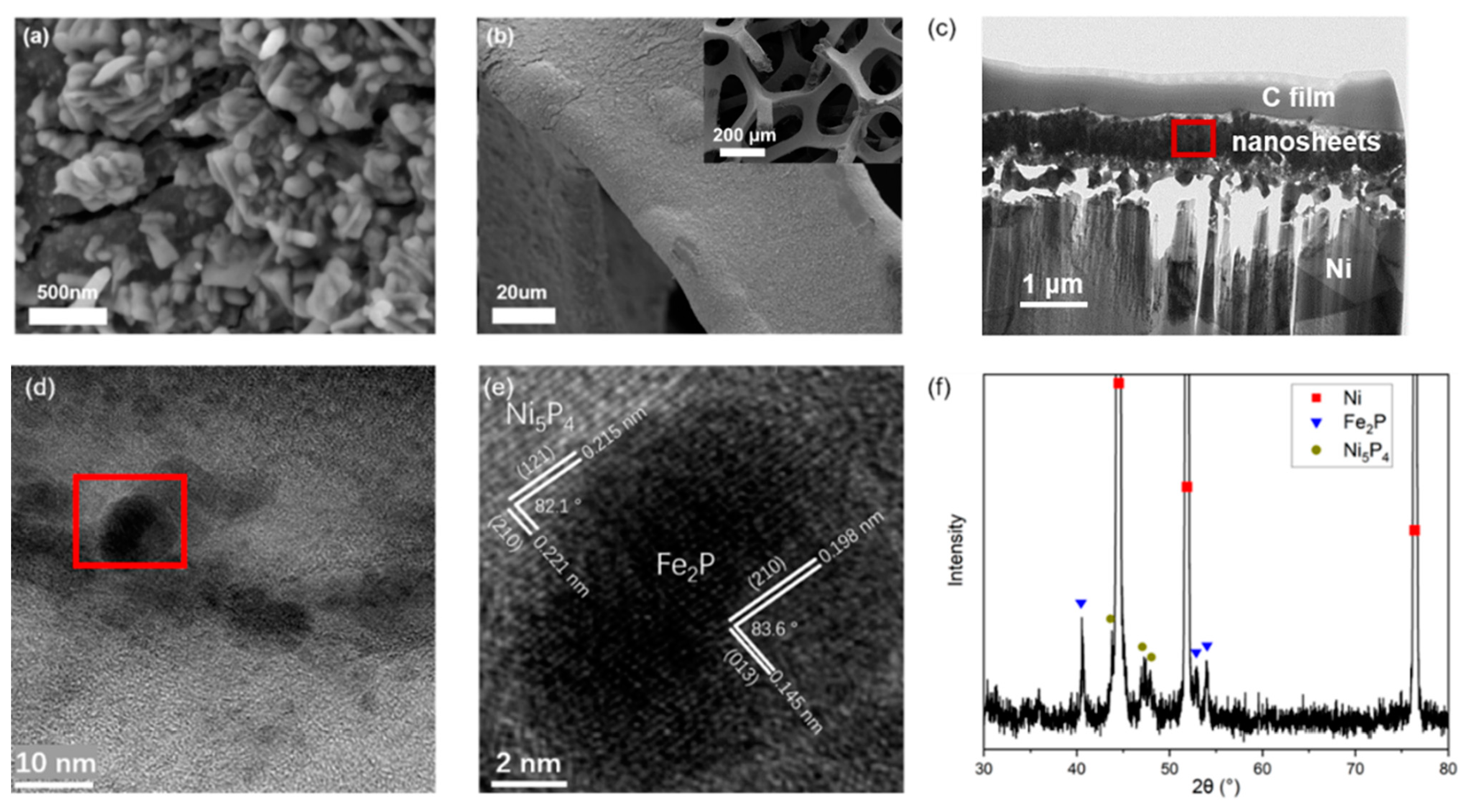
Figure 3.
(a) TEM image of NiFeP/NF; (b–d) EDS mapping images of Ni, Fe, and P on NiFeP/NF, respectively.
Figure 3.
(a) TEM image of NiFeP/NF; (b–d) EDS mapping images of Ni, Fe, and P on NiFeP/NF, respectively.
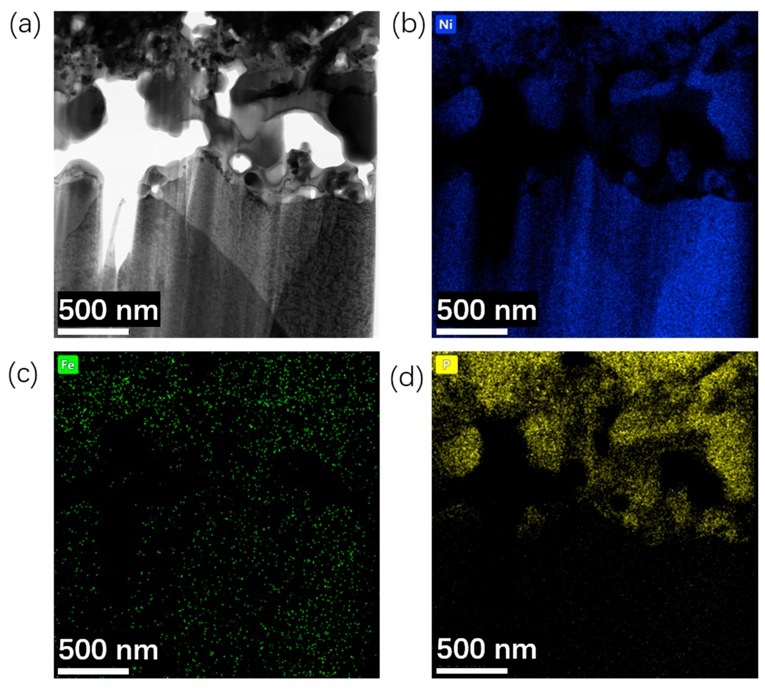
Figure 4.
(a) LSV curves of hydrogen evolution and oxygen evolution of NiFeP/NF prepared with different amounts of sodium hypophosphate; (b) Nyquist curve of NiFeP/NF prepared with different amounts of sodium hypophosphate; (c) Photographs of NiFeP/NF samples prepared with a dosage of 0.6 g sodium hypophosphate; (d) Hydrogen evolution and oxygen evolution LSV curves of NiFeP samples prepared with Fe(NO3)3 solution of different concentrations.

Figure 5.
(a) LSV curves of NiFeP/NF cathode before and after 700 h durability test, compared to commercial Pt/C and NF; (b) Tafel curves of NiFeP/NF cathode before and after 700 h durability test, Pt/C and NF; (c) LSV curves of NiFeP/NF anode before and after 700 h durability test, compared to commercial RuO2 and NF; (d) Tafel curves of NiFeP/NF anode before and after 700 h durability test, RuO2 and NF; (e) NiFeP/NF potential curve at 100 mA/cm2 constant current.
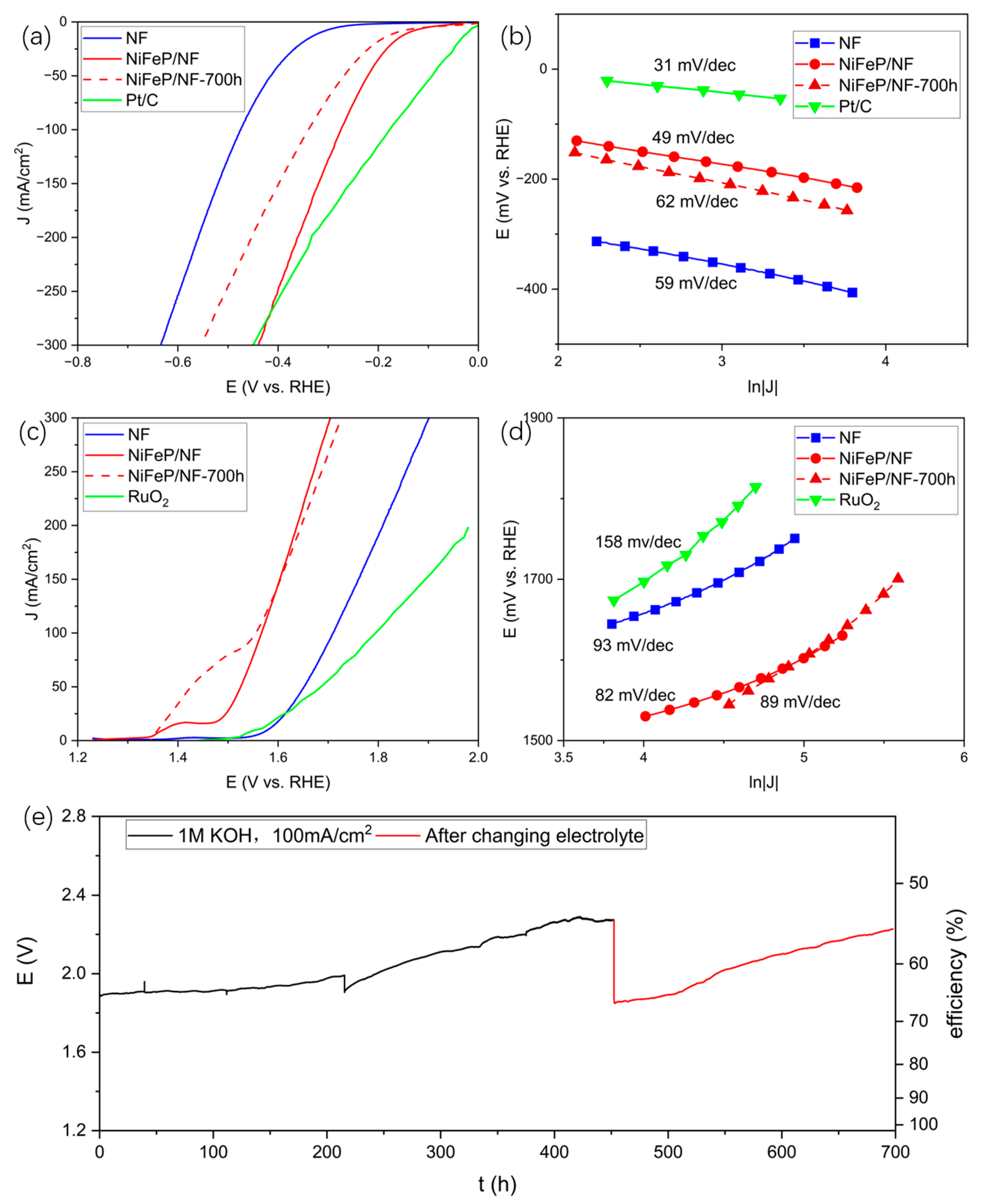
Figure 6.
SEM images of surface morphologies of NiFeP/NF before and after 200 h electrolytic water splitting: (a) Surface morphology of NiFeP/NF before reaction; (b) Surface morphology of NiFeP/NF after anode reaction; (c) Surface morphology of NiFeP/NF after cathode reaction.
Figure 6.
SEM images of surface morphologies of NiFeP/NF before and after 200 h electrolytic water splitting: (a) Surface morphology of NiFeP/NF before reaction; (b) Surface morphology of NiFeP/NF after anode reaction; (c) Surface morphology of NiFeP/NF after cathode reaction.

Figure 7.
XRD pattern of NiFeP/NF cathode before and after hydrogen evolution in water electrolysis for 200 h.
Figure 7.
XRD pattern of NiFeP/NF cathode before and after hydrogen evolution in water electrolysis for 200 h.

Figure 8.
XPS test results of NiFeP/NF before and after 200 h of oxygen evolution: (a) Full spectrum of XPS; (b) XPS surface element analysis; (c) Ni 2p high-resolution spectrum; (d) Fe 2p high-resolution spectrum; (e) P 2p high-resolution spectrum.
Figure 8.
XPS test results of NiFeP/NF before and after 200 h of oxygen evolution: (a) Full spectrum of XPS; (b) XPS surface element analysis; (c) Ni 2p high-resolution spectrum; (d) Fe 2p high-resolution spectrum; (e) P 2p high-resolution spectrum.

Figure 9.
SEM images of surface morphologies of NiFeP-TiO2/NF before and after 200 h electrolytic water splitting: (a) Surface morphology of NiFeP-TiO2/NF before reaction; (b) Surface morphology of NiFeP-TiO2/NF after anode reaction; (c) Surface morphology of NiFeP-TiO2/NF after cathode reaction.
Figure 9.
SEM images of surface morphologies of NiFeP-TiO2/NF before and after 200 h electrolytic water splitting: (a) Surface morphology of NiFeP-TiO2/NF before reaction; (b) Surface morphology of NiFeP-TiO2/NF after anode reaction; (c) Surface morphology of NiFeP-TiO2/NF after cathode reaction.
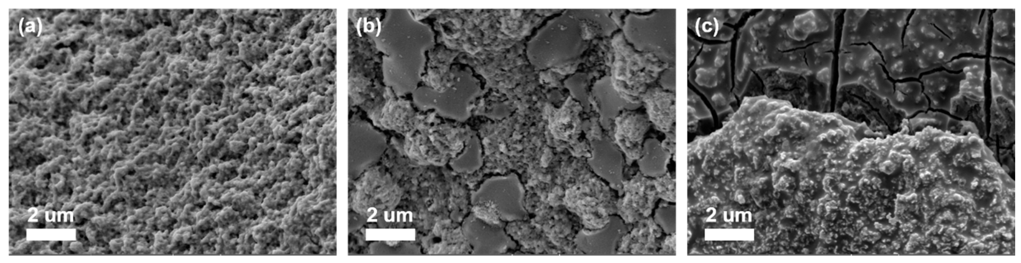
Figure 10.
Electrochemical tests of NiFeP-TiO2/NF: (a) LSV curves of samples; (b) The current-change curve of samples measured at a constant potential of 1.8 V; (c) Curve of total hydrogen production over time; (d) The LSV curves of NiFeP/NF and NiFeP-TiO2/NF were fully dissolved in the two-electrode system after continuous electrolysis at 1.8 V constant potential for a period of time.
Disclaimer/Publisher’s Note: The statements, opinions and data contained in all publications are solely those of the individual author(s) and contributor(s) and not of MDPI and/or the editor(s). MDPI and/or the editor(s) disclaim responsibility for any injury to people or property resulting from any ideas, methods, instructions or products referred to in the content. |
© 2023 by the authors. Licensee MDPI, Basel, Switzerland. This article is an open access article distributed under the terms and conditions of the Creative Commons Attribution (CC BY) license (https://creativecommons.org/licenses/by/4.0/).
Share and Cite
MDPI and ACS Style
Han, Q.; Wu, H.; Li, F.; Liu, J.; Zhao, L.; Zhang, P.; Gao, L. Self-Standing Hierarchical Porous Nickel-Iron Phosphide/Nickel Foam for Long-Term Overall Water Splitting. Catalysts 2023, 13, 1242. https://doi.org/10.3390/catal13091242
AMA Style
Han Q, Wu H, Li F, Liu J, Zhao L, Zhang P, Gao L. Self-Standing Hierarchical Porous Nickel-Iron Phosphide/Nickel Foam for Long-Term Overall Water Splitting. Catalysts. 2023; 13(9):1242. https://doi.org/10.3390/catal13091242
Chicago/Turabian StyleHan, Qixian, Hongmei Wu, Feng Li, Jing Liu, Liping Zhao, Peng Zhang, and Lian Gao. 2023. "Self-Standing Hierarchical Porous Nickel-Iron Phosphide/Nickel Foam for Long-Term Overall Water Splitting" Catalysts 13, no. 9: 1242. https://doi.org/10.3390/catal13091242
Note that from the first issue of 2016, this journal uses article numbers instead of page numbers. See further details here.