Article

Study on the Inhibition of Hydrogen Evolution Reaction by Electrocatalytic Reduction of Carbon Dioxide Using Elsholtzia Harchowensis Biochar

Department of Environmental Science and Engineering, University of Shanghai for Science and Technology, Shanghai 200093, China
*
Author to whom correspondence should be addressed.
These authors contributed equally to this work.
Catalysts 2024, 14(3), 172; https://doi.org/10.3390/catal14030172
Submission received: 22 January 2024 / Revised: 22 February 2024 / Accepted: 22 February 2024 / Published: 27 February 2024

Abstract

:
With the widespread application of plant remediation technology in the field of soil remediation, there was an increasing stock of hyperaccumulating plant tissues containing heavy metals, but there was currently a lack of effective disposal methods. In the preliminary research process, researchers used the copper hyperaccumulating plant Elsholtzia Harchowensis to prepare biochar material electrodes and successfully used them in the electrocatalytic reduction of carbon dioxide (CO2) process. Due to the previous research being conducted in aqueous solutions, the hydrogen evolution reaction (HER) on the working electrode surface has a certain impact on the Faraday efficiency (FE) of carbon-containing products. In order to further improve the electrocatalytic reduction performance of biochar materials, this study was based on B- and N-doped biochar prepared from Elsholtzia Harchowensis as raw material. The influence mechanisms of electrode surface hydrophobicity and electrolyte components (PC/water) on the CO2RR and HER were studied, respectively. After dropwise coating PTFE on the surface of Cu/C-BN material, the hydrophobicity of Cu/C-BN-PT material was improved, and the effect on the active sites of the catalyst was relatively small without changing the structure and elemental characteristics of the original electrode. In a 1.0 M KHCO3 solution, the Faraday efficiency of H2 in Cu/C-BN-PT material decreased by 20.1% compared to Cu/C-BN at −0.32 V (vs. RHE), indicating that changing the hydrophilicity of the material can significantly inhibit the HER. In a solution of PC/water at a ratio of 9:1 (V:V), the FE of converting CO2 to methane (CH4) at −0.32 V (vs. RHE) reached 12.0%, and the FE of carbon monoxide (CO) reached 64.7%. The HER was significantly inhibited, significantly improving the selectivity of electrocatalytic CO2.

1. Introduction

Elsholtzia Harchowensis, a copper indicator plant and copper hyperaccumulator, grows naturally in abundance in copper mining areas, and it has also been widely planted and utilized as a phytoremediation tool for the remediation of copper tailings soil [1,2,3,4]. With the wide application of phytoremediation technologies, the total amount of harvested hyperaccumulated plants has increased. Traditional post-disposal methods, such as incineration, have been gradually phased out due to the potential risk of secondary contamination with heavy metals and the high cost of heavy metal recovery [5,6]. Traditional post-disposal methods, such as incineration, have been gradually phased out due to the potential risk of secondary contamination with heavy metals and the high cost of heavy metal recovery [7,8].
In recent years, the significant increase in CO2 concentration has caused hazards such as global climate change, glacier melting, and rising sea levels. In order to address climate change and reduce CO2 concentration in the atmosphere, scientists have invested a lot of effort in developing advanced technologies for CO2 capture, utilization, and storage [9]. Among them, the use of renewable energy sources for electrocatalytic CO2RR to produce high-value-added products provides a feasible way to realize a carbon-neutral energy cycle and has a good application prospect in alleviating the energy crisis and climate problems [10,11]. In CO2RR research, compared with precious metal catalysts, biomass carbon catalysts have the advantages of abundant raw material sources and reserves, a simple preparation process, easy adjustment of porosity and surface functional groups, acid and alkali resistance, high-temperature stability, and environmental friendliness, and thus are considered to be one of the most promising CO2RR catalysts [12,13,14]. Meanwhile, Cu is currently known as the only element that can effectively electrocatalyze the reduction of CO2 to produce high-value-added multicarbon products [15,16,17,18]. Therefore, the application of Elsholtzia Harchowensis, which is rich in copper, in the field of CO2RR is considered an effective exploration of its sustainable resource utilization. In the preliminary research, our laboratory has conducted experiments on Elsholtzia Harchowensis in the field of electrochemical reduction of CO2. For example, Chen prepared biochar electrocatalytic materials from the copper hyperaccumulating plant Elsholtzia Harchowensis for CO2RR experiments. It found that the copper content in the collected Elsholtzia Harchowensis was 0.6%. In the absence of a catalytic effect after direct carbonization of the raw materials, Cu and S elements were subsequently introduced, achieving good results; the FE of CO was as high as 75% [19]. Considering the influence of non-metallic elements, Liu used non-metallic B- and N-doped modified Elsholtzia Harchowensis to prepare biochar electrocatalytic materials, which improved the electrochemical activity of the single metal-carbon material, further enhanced the electrochemical performance and selectivity for the product CH4. The FE of CH4 can reach up to 31%, proving the selective regulation of the product by non-metallic elements [20].
In the aforementioned studies, water was indeed used as the reaction medium in the electrochemical reduction of CO2 experiments. Due to the presence of water molecules in the solution, the common competing side reaction was the HER, which significantly affects the selectivity of products and catalytic efficiency. Especially at more negative voltages, the HER can reach up to 90% [21,22]. The strong competitiveness of HRE efficiency leads to a low efficiency of CO2RR, and a high hydrogen content in the product is also not conducive to the utilization of catalytic products. This is a challenge faced in current research, and further studies are needed to address this issue and improve the selectivity and efficiency of CO2RR. Currently, there have been numerous studies in the field of electrocatalytic reduction of CO2 to suppress the HER. For example, organic solvents have been selected as electrolyte solutions to enhance the solubility of CO2 and inhibit the HER [23]. Improving the hydrophobicity of electrode materials, such as surface coating with polytetrafluoroethylene, has shown good results in suppressing the HER [24,25]. Introducing ion-type surfactants into aqueous electrolytes has increased the FE of CO production from 50% to 95% [14]. Applying a hydrogen partial pressure of 4 bar can completely avoid HER at −0.05 V (vs. RHE) and 1 bar CO2 pressure [26]. VALENTI M et al. used bimetallic alloy catalysts to suppress the HER [27].
To further enhance the performance of Elsholtzia Harchowensis biomass biochar catalyst, this study is based on the electrode material Cu/C-BN prepared by modifying Elsholtzia Harchowensis biochar with B and N doping. We employed electrochemical deposition on the material surface to increase hydrophobic branches (material Cu/C-BN-CC, see Materials and Methods, Section 3 for details), drop-coated polytetrafluoroethylene (PTFE) to improve material hydrophobicity (material Cu/C-BN-PT, see Materials and Methods, Section 3 for details) and selected 90% PC (10% H2O) organic solvent electrolyte as a means to inhibit HER. The effects of these measures on the electrocatalytic reduction of CO2 in Cu/C-BN materials were investigated by comparing the physical properties, electrochemical properties, and product differences before and after the modifications.

2. Results and Discussion

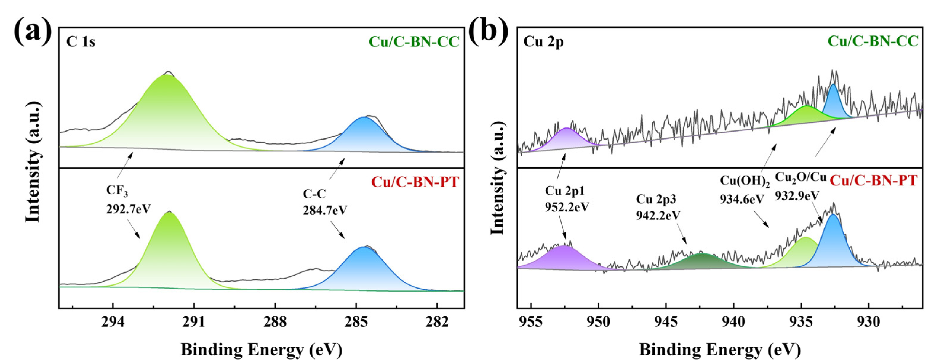
2.1. Catalyst Characterization

The morphological characteristics of Cu/C-BN-CC and Cu/C-BN-PT electrode materials were observed by scanning electron microscopy (SEM), and the results are shown in Figure 1. Compared with Cu/C-BN material (see Figure S1), the bulk structure of these two materials did not change, and the surface was still rough and had many particles. However, it was obvious that the bulks of these two materials were finer, and the fillers in the pores were more. This indicated that some groups were introduced onto the surface of Cu/C-BN-CC material after electrodeposition. Compared to Cu/C-BN-CC, Cu/C-BN-PT has a smoother surface with fewer pores and a higher filling degree of pores. This indicates that PTFE was uniformly distributed on the material surface, which increases the hydrophobicity of Cu/C-BN-PT material. Meanwhile, an energy dispersive spectrometer (EDS-elements mapping) was performed on the four elements C, O, Cu, and N of several catalyst materials (see Figure S2). Among them, a and b represent Cu/C-BN-CC and Cu/C-BN-PT materials, respectively (EDS layering images are shown in Figure S3), and the small image on the right shows the spectrograms of C, O, Cu, and N. The four elements C, O, Cu, and N in both materials were evenly distributed. The total spectrum of the element distribution diagram is shown in Figure S4. The proportion of C and Cu elements in Cu/C-BN-CC material has greatly increased compared to Cu/C-BN, indicating that many carbon-containing groups have been added to the surface of Cu/C-BN-CC material through electrodeposition, and the finer block-like structure has also exposed more metal sites. The proportion of elements in Cu/C-BN-PT material does not change significantly, indicating that the droplet coating of PTFE on the surface of the material does not cover the metal sites of the catalyst and does not affect the catalytic performance of the material while increasing its hydrophobicity.
Due to the experiment being conducted in an aqueous solution, the aqueous solution plays a role in transferring electrons during the catalytic reaction process. At the same time, there were a number of H+ at the cathode, and the hydrophilicity and hydrophobicity can affect the exposure of active sites on the catalyst surface and the electron transfer ability. The active sites on the surface of hydrophilic catalysts may be more easily surrounded by water molecules, thereby limiting the adsorption and reaction of reactants. The active sites on the surface of hydrophobic catalysts may be more easily in contact with non-polar reactant molecules. In order to investigate whether the different hydrophilicity and hydrophobicity of materials have an impact on CO2RR, the surface contact angles of three materials in aqueous solution were tested using a surface contact angle tester, and the results are shown in Figure 2. It is evident that the hydrophobicity of Cu/C-BN-CC materials was enhanced by the introduction of functional groups on the surface, while the addition of PTFE greatly enhances the hydrophobicity of the material, thereby suppressing the HER in the system. This indicates that the stronger the hydrophobicity of catalytic materials, the better their inhibitory effect on HER in aqueous solutions.
In order to better understand the crystal structure changes of elements on the material surface, XRD was used to analyze the sample, and the test results are shown in Figure 3a (Cu/C-BN material data graph is shown in Figure S5). After processing, the collected graph data showed that the main components in Cu/C-BN-CC and Cu/C-BN-PT materials were still graphite carbon, Cu2O, and Cu. This indicates that neither electrodeposition nor the addition of PTFE on the surface has changed the crystal properties of the materials, and the materials still maintain their original crystal structure. Diffraction peaks at 2 θ = 26.23, 44.36, and 53.97 correspond to the (002), (101), and (004) crystal planes of graphite carbon, with diffraction peaks at 2 θ = 29.58 and 36.44 correspond to the (110) and (111) crystal planes of Cu2O, with diffraction peaks at 2 θ = 43.32 and 50.45 correspond to the (111) and (200) crystal planes of Cu [16]. Figure 3b was the XPS full spectrum of the material, which shows the element’s composition and chemical valence state of the sample surface. XPS further proves the existence of C, O, Cu, B, N, and other elements in the material. The proportion of each element peak in the two materials is basically consistent, which echoes the SEM results, indicating that neither of the two materials changes the structure and element characteristics of the raw material.
Figure 4 and Figure S6 show the XPS fine spectra of B 1s, C 1s, Cu 2p, and N 1s of Cu/C-BN-CC and Cu/C-BN-PT materials. By comparing with the XPS fine spectrum of Cu/C-BN material (see Figure S7), it can be seen from the fine spectrum of Cu element that the peak positions of Cu 2p in Cu/C-BN-CC and Cu/C-BN-PT materials are basically consistent, especially the peak of Cu2O still appears at 923.9 eV in Cu/C-BN-CC and Cu/C-BN-PT materials, which is consistent with the results of SEM and XRD. Due to the close position of the binding energy peaks between Cu0 and Cu+ and the XRD results indicating that the proportion of Cu0 was extremely small, Cu in both materials mainly exists in the form of Cu+ and Cu2+, while the proportion of Cu2+ in Cu/C-BN-CC materials was slightly reduced [28]. The peak positions of C 1s, B 1s, O 1s, and N 1s have not changed, and the proportions of each peak remain roughly unchanged, indicating that the valence states of the elements in both materials have not changed much. B and N form chemical bonds on the surface of the material, while O partially forms oxides with the metal and mostly combines with C to form carbon oxides. In summary, both electrodeposition and surface coating with PTFE have little effect on the structure and elemental characteristics of the material but significantly alter its hydrophilic and hydrophobic properties.

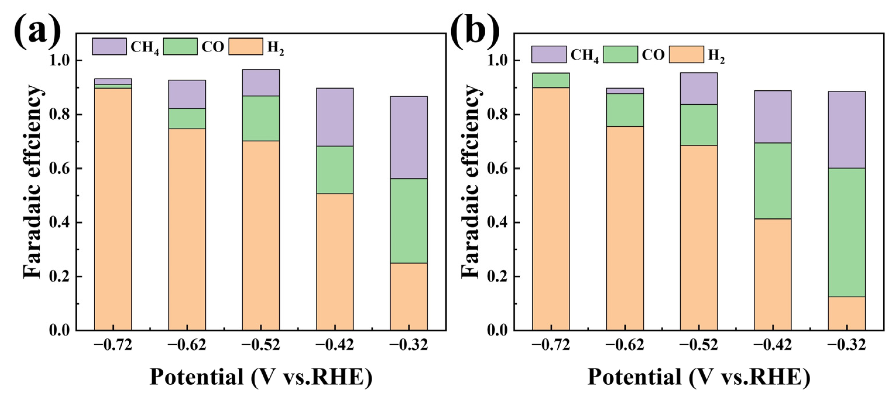
2.2. Impact of Hydrophobicity Enhancement on Electrochemical Performance

Figure 5 shows the linear sweep voltammetry (LSV) curves of Cu/C-BN-CC in Figure 5a and Cu/C-BN-PT in Figure 5c electrode materials in a 0.2 M Na2SO4 solution at a scanning rate of 10 mV/s. From the graph, there was a difference in the linear voltammetry curves of Cu/C-BN-CC and Cu/C-BN-PT materials under Ar and CO2 atmospheres. This is because under the conditions of introducing carbon dioxide, not only the HER occurs, but also CO2RR occurs. Therefore, the two materials have a certain electrocatalytic reduction effect on CO2. Compared to Cu/C-BN (see Figure S8), the current density of both materials has decreased, possibly due to the hydrophilicity and hydrophobicity of the materials affecting the catalytic reaction. Cu/C-BN-PT has a greater decrease in current density than Cu/C-BN-CC, which confirms the results of surface contact angle. Figure 5b,d shows the impedance test results of Cu/C-BN-CC and Cu/C-BN-PT electrocatalytic reduction of CO2 under different potential conditions. The fitting results show that the charge transfer resistance gradually decreases with the negative shift of potential, and the open circuit potential of Cu/C-BN-PT also shows a slight deviation toward the positive direction. The material impedances of Cu/C-BN, Cu/C-BN-CC, and Cu/C-BN-PT under open circuit potential (OCP) were 1.8 Ω, 1.2 Ω, and 155.2 Ω, respectively (detailed data can be found in Tables S1–S3). This indicates that the charge transfer resistance of Cu/C-BN-CC remains basically unchanged in the electrocatalytic CO2 reaction and the open circuit potential impedance of Cu/C-BN-PT material increases by more than 80 times. This indicates that adding PTFE to the surface of the material increases the difficulty of the overall catalytic reaction in the system, which is likely due to the enhanced hydrophobicity of the material, leading to a decrease in HER.
To understand the actual catalytic reaction process, the electrocatalytic products of two materials in a 1.0 M KHCO3 solution were collected using an airbag for detection during constant potential electrolysis at different potentials. The results are shown in Figure 6 (values are detailed in Tables S4–S6). The main gas-phase products of Cu/C-BN-CC and Cu/C-BN-PT materials were still hydrogen (H2), carbon monoxide (CO), and methane (CH4). Compared to Cu/C-BN, the HER rate of Cu/C-BN-CC material was slightly reduced. The FE of H2 was reduced by 8.6% at −0.32 V (vs. RHE), while the FE of H2 in Cu/C-BN-PT material was reduced by 20.1% at −0.32 V (vs. RHE). This indicates that changing the hydrophilicity and hydrophobicity of the material can have a certain inhibitory effect on the HER. The stronger the hydrophobicity of the material, the better the inhibitory effect on the HER.

2.3. The Influence of Organic Solvent Electrolytes on Electrochemical Performance

Due to the higher CO2 solubility of organic solvent electrolytes and the almost absence of HER, non-aqueous electrolytes were selected as the electrolyte solution for electrocatalytic CO2 reduction to improve the electrocatalytic performance of the material. 0.5 M H2SO4 aqueous solution was selected as the anode electrolyte, and 0.7 M tetraethyl ammonium chloride (TEACl) was used as the cathode electrolyte dissolved in a mixed solution of 10 v % water and 90 v % propylene carbonate (PC). Figure 7a shows the LSV curve of Cu/C-BN electrode material in a 90% PC (10% H2O) solution at a scanning rate of 10 mV/s. The significant negative shift in the initial potential of the material indicates that the charge transfer and reaction process on the electrode surface have been affected. The current density significantly decreases at the same potential, indicating that a certain catalytic reaction was restricted. However, the difference in current density between two different atmospheres increases, and the CO2RR is significantly enhanced. This is likely due to the weakening of competitiveness in hydrogen evolution reactions in non-aqueous solutions. Figure 7b shows the impedance test results of Cu/C-BN materials under different potential conditions. As shown in the figure, the OCP of Cu/C-BN changed in a 90% PC (10% H2O) solution, and the impedance of Cu/C-BN at the OCP was 48.4 Ω (detailed data can be found in Table S7). The charge transfer resistance of Cu/C-BN electrocatalytic carbon dioxide reaction in this non-aqueous solution increased by about 8 times. Figure 7c shows the i-t curves of Cu/C-BN under different potentials, showing a trend of first decreasing, then increasing, and then stabilizing. As the potential shifts negatively, the current density gradually increases. After 8 h of stable catalytic reduction of CO2, the catalyst still exhibits good catalytic performance, indicating that the catalyst has a certain degree of stability in this system. During constant potential electrolysis, gas bags were used to collect products for offline detection of their composition. Figure 7d shows the distribution of products generated by the electrocatalytic reduction of CO2 at different potentials. It can be seen from the figure that after using non-aqueous electrolyte solutions, the HER of the reaction was fully suppressed, and the total FE of CO and CH4 products was greatly improved. The FE of converting CO2 to CH4 at −0.32 V (vs. RHE) was 12.0%, and the FE of CO was 64.7% (see Table S8 for details).

3. Materials and Methods

3.1. Experimental Reagents and Materials

Dimethyl formamide (DMF, AR), polytetrafluoroethylene (PTFE, 60 wt%), sodium acetate (CH3COONa, AR), sodium potassium tartrate (NaKC4H4O6, AR), propylene carbonate (PC, 99%), sulfuric acid (H2SO4, AR), anhydrous sodium sulfate (Na2SO4, AR), anhydrous ethanol (CH3CH2OH, AR), potassium bicarbonate (KHCO3, AR), and urea (CH4N2O, AR) were all purchased from China National Pharmaceutical Group Corporation (Shanghai, China). Copper (II) chloride dihydrate (CuCl2·2H2O, AR), boric acid (H3BO3, GR), and tetraethylammonium chloride (TEACl, 98%) were purchased from Shanghai Macklin Biochemical Technology Co., Ltd. (Shanghai, China) 5% Nafion solution (D520) was purchased from Suzhou Yilong Energy Technology Co., Ltd. (Suzhou, China). All reagents were of analytical grade and used without further purification. The Elsholtzia Harchowensis was collected from the copper mining area in Tongling City, Anhui Province, China, located at a central latitude of 30°52′22.05″ N and a longitude of 118°01′42.09″ E. Its main elemental composition includes carbon (32.2%), hydrogen (13.8%), oxygen (48.6%), nitrogen (0.78%) and Copper (0.05%).

3.2. Preparation of Catalyst

3.2.1. Boron- and Nitrogen-Doped Copper Modified Biochar

The collected Elsholtzia harchowensis was washed, dried, crushed, and sieved through a 40 mesh sieve to obtain the powdered plant tissue. To a 30 mL DMF solution, 1.4 g of CuCl2, 1.00 g of urea, 1.12 g of boric acid, and 2 g of Elsholtzia harchowensis powder were added. The resulting powder was then dispersed under continuous stirring for 2 h. Afterward, the powder was allowed to stand for 24 h and subsequently placed in an oven at 105 °C. It was then transferred into a tube furnace and heated under N2 protection at 700 °C for 2 h with a heating rate of 2 °C /min. Once cooled, the powder was filtered and washed with water until it reached a neutral pH. Following the washing step, the powder was dried in an oven at 105 °C. Lastly, it was ground in an agate bowl to obtain the boron-and nitrogen-doped copper-modified biochar (Cu/C-BN) [29].

3.2.2. Hydrophobic Materials

The hydrophobic catalyst (Cu/C-BN-PT) was prepared by mixing 100 μL of 60 wt% PTFE dispersion with 1 mL of pure water, sonicating it in a sonicator for 30 min to make it well-mixed, and uniformly drop-coating it on the prepared Cu/C-BN working electrode [25].

3.2.3. Electrodeposited Materials

Carbon paper loaded with Cu/C-BN material was used as a cathode under a continuous CO2 gas stream at a flow rate of 20 mL/min. The catalyst (Cu/C-BN-CC) was prepared by electrodeposition method in a mixed solution consisting of 0.1 M sodium acetate, 0.2 M potassium sodium tartrate, and 1 M KHCO3 in the voltage range of 0.22~0.82 V (vs. RHE) using the chronocoulomb method [24,25].

3.2.4. Working Electrodes

7 mg of catalyst and 100 μL of 5% Nafion solution were mixed with 1 mL of anhydrous ethanol and sonicated for 1 h to make the catalyst uniformly dispersed. Then, the homogeneously mixed solution was drop-coated onto a 1 × 1.5 cm hydrophobic carbon paper with a catalyst loading of 2.2 mg/cm2 in several times and dried at room temperature. Before testing, the working electrode was immersed in 0.2 M Na2SO4 solution and reduced at −0.82 V (vs. RHE) potential for 3600 s for activation treatment.

3.3. Catalyst Characterization and Testing

3.3.1. Material Characterization

The X-ray diffractometer (XRD, Malvern Panalytical Empyrean, Almelo, The Netherlands) was tested using a Cu target as the radiation source at a scanning speed of 2°/min from 10° to 80°. A field emission scanning electron microscope (SEM, ZEISS GeminiSEM 300, Oberkochen, Germany) was used to observe the microscopic surface morphology of the materials, while the materials were scanned by an energy dispersive spectrometer elements mapping (EDS-elements mapping, ZEISS GeminiSEM 300, Oberkochen, Germany). The X-ray photoelectron spectrometer (XPS, Thermo Scientific ESCALAB 250Xi, Waltham, MA, USA) was load calibrated using a monochromatized Al Kα source (Mono Al Kα), hv = 1486.6 EV, with C 1s = 284.8 eV as standard. Surface contact angle (contact angle, JY-82C, Chengde Dingsheng Testing Equipment Co., Beijing, China), place the prepared working electrode material on the testing platform, and automatically titrate the water droplets using the static drop method. Measure the contact angle using a high-volume method.

3.3.2. Electrochemical Tests

The electrocatalytic CO2RR was carried out in an H-type electrolytic cell with the cathode chamber separated from the anode chamber by a DuPont N-117 proton exchange membrane, and the volume of the electrolyte in both chambers was 50 mL. Platinum sheet (2 × 2 cm) and Ag/AgCl electrodes were used for the counter and reference electrodes, respectively. Following a 95% iR compensation, all electrode potentials (vs. Ag/AgCl) in the experiment could be converted to standard electrode potentials (vs. RHE) using Equation (1).
E(vs. RHE) = E(vs. Ag/AgCl) + 0.197 V + 0.0591 × pH,
All electrochemical tests were performed using an electrochemical workstation (CHI660E, Shanghai Chenhua Instrument Co., Ltd., Shanghai, China). Before the test, high-purity argon gas (99.999%) was introduced into the cathode area for 30 min to remove air from the system. Then, high-purity carbon dioxide (99.99%) was introduced for 30 min to saturate the electrolyte solution with carbon dioxide. Throughout the experiment, a constant flow of carbon dioxide gas was supplied at a rate of 20 mL/min. The catalyst was initially activated by reduction at a potential of −0.82V (vs. RHE) for a duration of 3600 s. Then, the catalyst was tested using linear sweep voltammetry (LSV) with a scan rate of 10 mV/s in the potential range of 0 to −0.82V (vs. RHE). Using current density to evaluate the electrocatalytic performance of materials, the current density was obtained by dividing the measured current data by the geometric area of the material. Electrochemical impedance spectroscopy (EIS) was performed at potentials ranging from −0.32 to −0.72 V (vs. RHE), with a frequency range of 105 to 0.1 Hz and an amplitude of 5 mV. The ZView (Version: 2.9 c) software was used to perform linear fitting on it and obtain the Nyquist plot of the semicircular region. The fitted circuit diagram is shown in the impedance map. In the i-t test, gas products were collected by a gas bag, and the cathode gas products were detected using gas chromatography (GC-9890B, Shanghai Linghua Instrument Co. Ltd., Shanghai, China) with a carrier gas of 99.999% high-purity argon, a gas quantitative injection tube with a capacity of 1 mL, a thermal conductivity detector (TCD, Shanghai Linghua Instrument Co. Ltd., Shanghai, China) temperature of 80 °C, and a column box temperature of 120 °C. In addition, another gas chromatography (GC2060, Shanghai Ruimin Instrument Co. Ltd., Shanghai, China) was carried out with a carrier gas of 99.999% high-purity nitrogen, an injector temperature of 150 °C, a column box temperature of 50 °C, a hydrogen-ion flame detector (FID, Shanghai Ruimin Instrument Co. Ltd., Shanghai, China) temperature of 150 °C, and a conversion oven temperature of 330 °C.

4. Conclusions

In summary, after dripping PTFE onto the surface of Cu/C-BN material, the resulting Cu/C-BN-PT material has a smoother surface with fewer pores, a higher filling degree of pores, and significantly improved hydrophobicity. However, it does not cover the metal sites of the catalyst and does not change the structure and elemental characteristics of the raw material. While increasing the hydrophobicity of the material, it does not affect the catalytic performance of the material. Compared to Cu/C-BN, the FE of H2 in Cu/C-BN-PT material decreased by 20.1% at −0.32 V (vs. RHE), and the enhanced hydrophobicity of the material led to a decrease in HER. Through the comparison of three materials, it was found that the stronger the hydrophobicity of the material, the more significant the inhibitory effect on HER. Subsequently, non-aqueous electrolytes were selected as the electrolyte solution for electrocatalytic CO2 reduction. In a 90% PC (10% H2O) solution, the FE of CO2 conversion to CH4 reached 12.0% at −0.32 V (vs. RHE), and the FE of CO reached 64.7%, effectively suppressing the HER of the reaction. Improving the hydrophobicity of materials and using organic solvents as electrolytes can significantly inhibit the HER of Elsholtzia Harchowensis biomass carbon catalyst in CO2RR, effectively enhancing its electrochemical performance, providing further theoretical support for the large-scale resource utilization of copper accumulation plant Elsholtzia Harchowensis, and also providing a reference for suppressing competitive the HER.

Supplementary Materials

The following supporting information can be downloaded at: https://www.mdpi.com/article/10.3390/catal14030172/s1. Figure S1: SEM image of Cu/C-BN material; Figure S2: EDS-elements mapping of Cu/C-BN-CC (a) and Cu/C-BN-PT (b) materials; Figure S3: EDS layering images of Cu/C-BN-CC and Cu/C-BN-PT materials. (a). Cu/C-BN-CC material. (b). Cu/C-BN-PT; Figure S4: Total number of elemental distribution maps for Cu/C-BN, Cu/C-BN-CC, and Cu/C-BN-PT materials. (a). Cu/C-BN-CC. (b). Cu/C-BN-PT. (c). Cu/C-BN; Figure S5: XRD and XPS images of Cu/C-BN materials. (a). XRD. (b). XPS; Figure S6: Cu/C-BN-CC and Cu/C-BN-PT materials N 1s, B 1s, O 1s XPS fine spectrum; Figure S7: Cu/C-BN material B 1s, C 1s, Cu 2p, N 1s XPS fine spectrum; Figure S8: (a) LSV diagram of Cu/C-BN material in 0.2 M Na2SO4 solution. (b). Impedance diagram of Cu/C-BN in 1 M KHCO3 solution. (c). Product diagram of Cu/C-BN in 1 M KHCO3 solution; Table S1: EIS fitting data of Cu/C-BN material in 1.0 M KHCO3 solution; Table S2: EIS fitting data of Cu/C-BN-CC material in 1.0 M KHCO3 solution; Table S3: EIS fitting data of Cu/C-BN-PT material in 1.0 M KHCO3 solution; Table S4: Product efficiency of Cu/C-BN material at different potentials in 1.0 M KHCO3 solution; Table S5: Product efficiency of Cu/C-BN-CC material at different potentials in 1.0 M KHCO3 solution; Table S6: Product efficiency of Cu/C-BN-PT material at different potentials in 1.0 M KHCO3 solution; Table S7: EIS fitting data of Cu/C-BN material in 90% PC (10% H2O) solution; Table S8: Product efficiency of Cu/C-BN material at different potentials in 90% PC (10% H2O) solution.

Author Contributions

Conceptualization, Methodology, Investigation, Formal Analysis, Writing—Original Draft, W.L. (First Author); Data Curation, Software, Writing—Original Draft, S.C.; Visualization, Investigation, Validation, Z.M.; Methodology, Supervision, Writing—Review & Editing, L.L.; Conceptualization, Funding Acquisition, Resources, H.T. (Corresponding Author). All authors have read and agreed to the published version of the manuscript.

Funding

This research received no external funding.

Data Availability Statement

The data presented in this study are available on request from the corresponding author.

Conflicts of Interest

The authors declare no conflicts of interest.

References

  1. Jiang, L.; Yang, X.; He, Z. Growth response and phytoextraction of copper at different levels in soils by Elsholtzia splendens. Chemosphere 2004, 55, 1179–1187. [Google Scholar] [CrossRef] [PubMed]
  2. Song, J.; Zhao, F.-J.; Luo, Y.-M.; McGrath, S.P.; Zhang, H. Copper uptake by Elsholtzia splendens and Silene vulgaris and assessment of copper phytoavailability in contaminated soils. Environ. Pollut. 2004, 128, 307–315. [Google Scholar] [CrossRef] [PubMed]
  3. Tang, S.; Wilke, B.-M.; Huang, C. The uptake of copper by plants dominantly growing on copper mining spoils along the Yangtze River, the People’s Republic of China. Plant Soil 1999, 209, 225–232. [Google Scholar] [CrossRef]
  4. Liu, J.; Xiong, Z.T. Differences in accumulation and physiological response to copper stress in three populations of Elsholtzia haichowensis S. Water Air Soil Pollut. 2005, 168, 5–16. [Google Scholar] [CrossRef]
  5. Li, J.-T.; Gurajala, H.K.; Wu, L.-H.; van der Ent, A.; Qiu, R.-L.; Baker, A.J.M.; Tang, Y.-T.; Yang, X.-E.; Shu, W.-S. Hyperaccumulator Plants from China: A Synthesis of the Current State of Knowledge. Environ. Sci. Technol. 2018, 52, 11980–11994. [Google Scholar] [CrossRef] [PubMed]
  6. Liu, Z.; Tran, K.-Q. A review on disposal and utilization of phytoremediation plants containing heavy metals. Ecotoxicol. Environ. Saf. 2021, 226, 112821. [Google Scholar] [CrossRef]
  7. Sas-Nowosielska, A.; Kucharski, R.; Małkowski, E.; Pogrzeba, M.; Kuperberg, J.; Kryński, K. Phytoextraction crop disposal—An unsolved problem. Environ. Pollut. 2004, 128, 373–379. [Google Scholar] [CrossRef]
  8. Cui, P.; Liu, C.; Su, X.; Yang, Q.; Ge, L.; Huang, M.; Dang, F.; Wu, T.; Wang, Y. Atomically Dispersed Manganese on Biochar Derived from a Hyperaccumulator for Photocatalysis in Organic Pollution Remediation. Environ. Sci. Technol. 2022, 56, 8034–8042. [Google Scholar] [CrossRef]
  9. Yu, J.; Wang, J.; Ma, Y.; Zhou, J.; Wang, Y.; Lu, P.; Yin, J.; Ye, R.; Zhu, Z.; Fan, Z. Recent Progresses in Electrochemical Carbon Dioxide Reduction on Copper-Based Catalysts toward Multicarbon Products. Adv. Funct. Mater. 2021, 31, 2102151. [Google Scholar] [CrossRef]
  10. Liotta, L.F.; Wu, H. CO2 Capture, Utilization and Storage: Catalysts Design. Catalysts 2024, 14, 80. [Google Scholar] [CrossRef]
  11. Lin, R.; Guo, J.; Li, X.; Patel, P.; Seifitokaldani, A. Electrochemical Reactors for CO2 Conversion. Catalysts 2020, 10, 473. [Google Scholar] [CrossRef]
  12. Yang, B.; Chen, L.; Xue, S.; Sun, H.; Feng, K.; Chen, Y.; Zhang, X.; Xiao, L.; Qin, Y.; Zhong, J.; et al. Electrocatalytic CO2 reduction to alcohols by modulating the molecular geometry and Cu coordination in bicentric copper complexes. Nat. Commun. 2022, 13, 5122. [Google Scholar] [CrossRef] [PubMed]
  13. Qiu, C.; Qian, K.; Yu, J.; Sun, M.; Cao, S.; Gao, J.; Yu, R.; Fang, L.; Yao, Y.; Lu, X.; et al. MOF-Transformed In2O3-x@C Nanocorn Electrocatalyst for Efficient CO2 Reduction to HCOOH. Nano-Micro Lett. 2022, 14, 167. [Google Scholar] [CrossRef]
  14. Wang, H.; Jia, J.; Song, P.; Wang, Q.; Li, D.; Min, S.; Qian, C.; Wang, L.; Li, Y.F.; Ma, C.; et al. Efficient Electrocatalytic Reduction of CO2 by Nitrogen-Doped Nanoporous Carbon/Carbon Nanotube Membranes: A Step Towards the Electrochemical CO2 Refinery. Angew. Chem. Int. Ed. 2017, 56, 7847–7852. [Google Scholar] [CrossRef] [PubMed]
  15. Hori, Y. Electrochemical CO2 Reduction on Metal Electrodes. In Modern Aspects of Electrochemistry; Vayenas, C.G., White, R.E., Gamboa-Aldeco, M.E., Eds.; Springer: New York, NY, USA, 2008; pp. 89–189. [Google Scholar]
  16. Gu, Z.; Shen, H.; Shang, L.; Lv, X.; Qian, L.; Zheng, G. Nanostructured Copper-Based Electrocatalysts for CO2 Reduction. Small Methods 2018, 2, 1800121. [Google Scholar] [CrossRef]
  17. Wu, B.; Chen, J.; Qian, L. Recent Advances in Heterogeneous Electroreduction of CO2 on Copper-Based Catalysts. Catalysts 2022, 12, 860. [Google Scholar] [CrossRef]
  18. Hong, X.; Zhu, H.; Du, D.; Zhang, Q.; Li, Y. Research Progress of Copper-Based Bimetallic Electrocatalytic Reduction of CO2. Catalysts 2023, 13, 376. [Google Scholar] [CrossRef]
  19. Chen, S.; Liu, W.; Mei, Z.; Li, H.; Zhao, W.; Zhao, J.; Tao, H. The synthesis of copper-modified biochar from Elsholtzia Harchowensis and its electrochemical activity towards the reduction of carbon dioxide. Front. Chem. 2023, 11, 1238424. [Google Scholar] [CrossRef]
  20. Liu, W.; Chen, S.; Mei, Z.; Li, L.; Li, H.; Zhao, W.; Tao, H. Boron and nitrogen doping modulating the coordination environment of copper in biochar for reformative electrocatalytic CO2 reduction. Surf. Interfaces 2024, 44, 103608. [Google Scholar] [CrossRef]
  21. Costentin, C.; Robert, M.; Savéant, J.-M. Catalysis of the electrochemical reduction of carbon dioxide. Chem. Soc. Rev. 2012, 42, 2423–2436. [Google Scholar] [CrossRef]
  22. Kumar, B.; Llorente, M.; Froehlich, J.; Dang, T.; Sathrum, A.; Kubiak, C.P. Photochemical and Photoelectrochemical Reduction of CO2. Annu. Rev. Phys. Chem. 2012, 63, 541–569. [Google Scholar] [CrossRef] [PubMed]
  23. Burgers, I.; Pérez-Gallent, E.; Goetheer, E.; Kortlever, R. Electrochemical CO2 Reduction on Copper in Propylene Carbonate: Influence of Water Content and Temperature on the Product Distribution. Energy Technol. 2023, 11, 2201465. [Google Scholar] [CrossRef]
  24. Fang, M.; Wang, M.; Wang, Z.; Zhang, Z.; Zhou, H.; Dai, L.; Jiang, L. Hydrophobic, Ultrastable Cuδ+ for Robust CO2 Electroreduction to C2 Products at Ampere-Current Levels. J. Am. Chem. Soc. 2023, 145, 11323–11332. [Google Scholar] [CrossRef] [PubMed]
  25. An, P.; Wei, L.; Li, H.; Yang, B.; Liu, K.; Fu, J.; Li, H.; Liu, H.; Hu, J.; Lu, Y.-R.; et al. Enhancing CO2 reduction by suppressing hydrogen evolution with polytetrafluoroethylene protected copper nanoneedles. J. Mater. Chem. A 2020, 8, 15936–15941. [Google Scholar] [CrossRef]
  26. Blom, M.J.W.; van Swaaij, W.P.M.; Mul, G.; Kersten, S.R.A. Increased hydrogen partial pressure suppresses and reverses hydrogen evolution during Pd catalysed electrolysis of CO2. Sustain. Energy Fuels 2020, 4, 4459–4463. [Google Scholar] [CrossRef]
  27. Valenti, M.; Prasad, N.P.; Kas, R.; Bohra, D.; Ma, M.; Balasubramanian, V.; Chu, L.; Gimenez, S.; Bisquert, J.; Dam, B.; et al. Suppressing H2 Evolution and Promoting Selective CO2 Electroreduction to CO at Low Overpotentials by Alloying Au with Pd. ACS Catal. 2019, 9, 3527–3536. [Google Scholar] [CrossRef]
  28. Liu, G.; Zheng, F.; Li, J.; Zeng, G.; Ye, Y.; Larson, D.M.; Yano, J.; Crumlin, E.J.; Ager, J.W.; Wang, L.-W.; et al. Investigation and mitigation of degradation mechanisms in Cu2O photoelectrodes for CO2 reduction to ethylene. Nat. Energy 2021, 6, 1124–1132. [Google Scholar] [CrossRef]
  29. Li, X.; Hu, Y.; Zhang, C.; Xiao, C.; Cheng, J.; Chen, Y. Electro-activating of peroxymonosulfate via boron and sulfur co-doped macroporous carbon nanofibers cathode for high-efficient degradation of levofloxacin. J. Hazard. Mater. 2023, 442, 130016. [Google Scholar] [CrossRef]
Figure 1. SEM images of Cu/C-BN-CC and Cu/C-BN-PT materials. (a,b) were Cu/C-BN-CC material. (c,d) were Cu/C-BN-PT material.
Catalysts 14 00172 g001
Figure 2. Surface contact angles of Cu/C-BN, Cu/C-BN-CC, and Cu/C-BN-PT materials. (a) Cu/C-BN-PT. (b) Cu/C-BN-CC. (c) Cu/C-BN.
Catalysts 14 00172 g002
Figure 3. XRD and XPS images of Cu/C-BN-CC and Cu/C-BN-PT materials. (a) XRD image. (b) XPS image.
Catalysts 14 00172 g003
Figure 4. Cu 2p (a) and C 1s (b) of Cu/C-BN-CC and Cu/C-BN-PT materials XPS fine spectrum.
Catalysts 14 00172 g004
Figure 5. Electrochemical test results of Cu/C-BN-CC and Cu/C-BN-PT materials. LSV plots of Cu/C-BN-CC (a) and Cu/C-BN-PT (c) in 0.2 M Na2SO4 solution; Impedance diagrams of Cu/C-BN-CC (b) and Cu/C-BN-PT (d) in 1 M KHCO3 solution.
Catalysts 14 00172 g005
Figure 6. Product distribution of Cu/C-BN-CC. (a) and Cu/C-BN-PT (b) materials electrocatalytic CO2 in 1.0 M KHCO3 solution.
Catalysts 14 00172 g006
Figure 7. Electrochemical testing and product diagram of Cu/C-BN material in 90% PC (10% H2O) solution. (a) LSV comparison chart. (b) Impedance diagrams at different potentials. (c) I-t curves at different potentials. (d) Product diagrams at different potentials.
Catalysts 14 00172 g007
Disclaimer/Publisher’s Note: The statements, opinions and data contained in all publications are solely those of the individual author(s) and contributor(s) and not of MDPI and/or the editor(s). MDPI and/or the editor(s) disclaim responsibility for any injury to people or property resulting from any ideas, methods, instructions or products referred to in the content.

