
Catalytic Decomposition of CH4 to Hydrogen and Carbon Nanotubes Using the Pt(1)-Fe(30)/MCM-41 Catalyst

Department of Chemical and Biomolecular Engineering, Chonnam National University, Yeosu 59626, Republic of Korea
Catalysts 2024, 14(4), 282; https://doi.org/10.3390/catal14040282
Submission received: 25 March 2024
/
Revised: 17 April 2024
/
Accepted: 18 April 2024
/
Published: 20 April 2024
(This article belongs to the Special Issue Study of Novel Catalysts for Methane Conversion)
Abstract
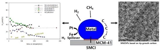
:The catalytic decomposition of CH4 to H2 and carbon nanotubes (CNTs) was investigated regarding Pt(1)-Fe(30)/MCM-41 and Fe(30)/MCM-41 using a fixed-bed flow reactor under an atmosphere. X-ray diffraction (XRD), X-ray photoelectron spectroscopy (XPS), scanning electron microscopy (SEM), energy dispersive spectroscopy (EDS), transmission electron microscope (TEM), and Raman spectroscopy were used to characterize the behavior of Pt(1)-Fe(30)/MCM-41 and Fe(30)/MCM-41. The hydrogen yield of Pt(1)-Fe(30)/MCM-41 was 3.2 times higher than that of Fe(30)/MCM-41. When 1 wt% of Pt was added to Fe(30)/MCM-41(Mobil Composition of Matter No. 41), the atomic percentage of Fe2p increased from 13.39% to 16.14% and the core Fe2p1/2 electron levels of Fe0 and Fe2+ chemically shifted to lower energies (0.2 eV and 0.1 eV, respectively) than those of Fe(30)/MCM-41. The Fe, Pt, Si, and O nanoparticles were uniformly distributed on the catalyst surface, and the average iron particle sizes of the Pt(1)-Fe(30)/MCM-41 and Fe(30)/MCM-41 were about 33.4 nm and 58.5 nm, respectively. This is attributed to the uniform distribution of the nano-sized iron particles on the MCM-41 surface, which was due to the suitable metal-carrier interaction (SMCI) between Fe, Pt, and MCM-41 and the high reduction degree of Fe due to the spillover effect of H2 from Pt to Fe. Pt(1)-Fe(30)/MCM-41 produced multiwalled CNTs and bamboo-shaped CNTs with high crystallinity and graphitization degree using the tip-growth mechanism, with an ID/IG ratio of 0.93 and a C(101)/C(002) ratio of 0.64.
1. Introduction
The catalytic decomposition of CH4(CDM) has garnered considerable attention as a promising method for hydrogen production. It offers a clean energy source that does not emit COx or other greenhouse gases, but produces only useful carbon materials, such as carbon nanotubes [1]. Methane is the main component of natural gas, and it is an endothermic reaction, as shown in Equation (1). However, CDM is difficult to implement because it is energy intensive and thermodynamically favors carbon formation, which rapidly deposits carbon on the catalyst surface and deactivates the catalyst.
Ashik et al. [2] proposed hydrogen production and CNT growth as follows.
where S is active sites. CNT growth initially occurs by cracking C–H bonds at active sites on the catalyst surface, resulting in atomic carbon deposition, followed by the dissolution and diffusion of carbon into metal nanoparticles. Finally, carbon deposition, nucleation, and filament formation occur behind the metal nanoparticles. Surendran et al. [3] reported on the synthesis of MWCNTs, which have a diameter in the range of 13 nm and a d-spacing of 0.33 nm, carried out at a relatively low temperature of 700 °C using liquified petroleum gas (LPG) as a hydrocarbon source and the chemical vapor deposition method. Suelves et al. [4] reported that Fe-based catalysts doped with Mo were prepared and tested in the catalytic decomposition of methane (CDM) and tubular carbon nanostructures with high structural order were obtained using Fe-Mo catalysts, mainly as multiwall carbon nanotubes (MWCNTs) and bamboo carbon nanotubes.
CH4 + 2S ⇄ CH3S + HS
CH3S + S ⇄ CH2S + HS
CH2S + S ⇄ CHS + HS
CHS + S ⇄ CS + HS
2HS ⇄ 2S + H2
However, the catalyst used for methane decomposition is rapidly deactivated due to carbon deposition. Activators such as CO2 and O2 are used for the regeneration of deactivated metal catalysts. Otsuka et al. [5] conducted a study on methane decomposition and regeneration using Ni/Al2O3, Ni/SiO2, Ni/TiO2, and Pd-Ni/SiO2 catalysts. They theorized that if the carbon deposited on the catalyst after the catalytic decomposition of methane is oxidized to oxygen or carbon dioxide, there is no need to supply energy in the partial oxidation reaction of methane to produce synthesis gas, and there is no generation of carbon dioxide.
Precious metals, such as Pd, Pt, Ru, and Rh, are useful for maintaining high activity and stability in CDM, but their industrial use is unsuitable as they are expensive and scarce. Using group VIII 3d transition metals, such as Fe and Ni, is an industrially viable alternative with the benefits of low cost and high availability. Fe- and Ni-based catalysts can produce liquid hydrocarbons from CO and H2 using the Fischer–Tropsch process [6]. They exhibit excellent initial catalytic activity, but carbon is quickly deposited on the catalyst surface and deactivates the catalyst [7,8,9,10,11,12,13,14]. Several strategies have been used to maintain the lifespan of 3D transition-metal-based group VIII catalysts and to prevent carbon deposition on the catalyst surface [15]. Using X-ray diffraction (XRD), Kutteri et al. [16] found that the crystal size of the bimetal catalyst was smaller than that of the single metal catalyst; they also reported that this was consistent with the increase in active sites. Naikoo et al. [17] reported that nickel, ruthenium, and platinum-based catalysts showed the highest activity and catalytic efficiency for carbon-free hydrogen synthesis in the methane thermal decomposition process. Pudukudy et al. [18] reported that the addition of Pt to Ni/CeO2 enhanced the activity and stability in a CDM reaction as the reduction temperature of NiO was decreased by hydrogen spillover and the uniform distribution of fine particles on the catalyst through moderate metal–carrier interaction. Karimi et al. [19] reported that a nickel-based catalyst containing an alkali, alkaline earth metal, transition metal (Fe, Co, Cu), noble metal (Pd, Pt), and rare earth metal (La) as a promoter was used in CDM for hydrogen production. When a promoter is appropriately added to a catalyst, its interaction increases catalytic activity and prevents carbon deposition on the catalyst. Shah et al. [20] reported that an Fe-M (M = Pd, Mo, Ni) binary catalyst supported on aluminum in the CDM had significantly higher activity than a single metal catalyst supported by Fe, Pd, Mo, and Ni. In a previous report, the decomposition temperature of methane was reduced to 400–500 °C compared to non-catalytic pyrolysis. Binary catalysts are believed to maintain catalytic activity for a long time in CDM [21,22,23,24,25,26,27,28,29,30] and prevent carbon deposition on the catalyst surface. MCM-41 [31] has pores ranging in sizes from 2 nm to 50 nm in a uniform hexagonal arrangement and is widely used as a catalyst carrier and adsorbent because of its physical properties, which include thick walls and high thermal stability. MCM-41 is a mesoporous material that can be used as a carrier for a carbon decomposition reactions and is a better carrier of catalyst than ZSM-5 zeolite, which has micropores that easily deposit carbon.
Rahimpour et al. [32] reported that the performance of a Cu-Fe bimetallic catalyst mounted onto an MCM-41 support in RWGS was investigated, and that MCM-41’s high specific surface area is advantageous for dispersing active metals and preventing their sintering. Lopez et al. [33] reported that when both K and Fe are incorporated as promotors into the Cu/MCM-41 catalyst, the reaction rate of syngas to oxygenated compounds is notably increased, especially for ethanol.
In this study, we investigated the effect of Pt in order to create a catalyst that maintained high activity and long-term stability in CDM. The catalysts used were characterized using XRD, XPS, SEM, EDS, TEM, and Raman spectroscopy. The catalysts were evaluated by performing catalyst performance tests in CDM using a fixed bed flow reactor under atmospheric pressure to obtain the CNTs and the hydrogen yield.
2. Results and Discussion
2.1. Activity of the Catalyst
Figure 1 shows the methane conversion versus reaction time of CDM over the Fe(30)/MCM-41, Ni(20)/MCM-41, Pt(1)/MCM-41, Pt(1)-Fe(30)/MCM-41, and Pt(1)-Ni(20)/MCM-41 catalysts. The numbers in parentheses indicate the percentage of weight carried. The methane conversion of the Pt(1)-Ni(20)/MCM-41 catalyst was lower than that of the Ni(20)/MCM-41 catalyst up until 100 min; however, the methane conversion of the Pt(1)-Fe(30)/MCM-41 catalyst was significantly higher than that of the Fe(30)/MCM-41 catalyst. From ca. 100 min until ca. 165.2 min, the methane conversion of Pt(1)-Ni(20)/MCM-41 and Pt(1)-Fe(30)/MCM-41 exhibited an increasing trend, reaching about 58.2% and 56.2%, respectively. Additionally, the methane conversion of the Pt(1)/MCM-41 catalyst continued to increase until 44.8 min, reaching 55.2%; however, it decreased rapidly thereafter, reaching 22.3% at 288.5 min. The initial activity of Fe(30)/MCM-41, Ni(20)/MCM-41, Pt(1)-Fe(30)/MCM-41, and Pt(1)-Ni(20)/MCM-41 at about 102.5 min was in the following order: Ni(20)/MCM-41 > Pt(1)-Ni(20)/MCM-41 > Pt(1)-Fe(30)/MCM-41 >> Fe(30)/MCM-41. Upon adding 1 wt% Pt promoter to the Ni(20)/MCM-41 and Fe(30)/MCM-41 catalyst, the methane conversion data exhibited a nearly identical trend after 160 min. Additionally, the hydrogen yield of Fe(30)/MCM-41, Ni(20)/MCM, Pt(1)/MCM-41, Pt(1)-Fe(30)/MCM-41, and Pt(1)-Ni(20)/MCM -41 (Figure 2) also showed the same trend as the methane conversion, with a yield of 9.73, 32.33, 11.9, 29.9, 39.1%, respectively, obtained at 165.2 min, respectively. The addition of the 1 wt% Pt promoter to Ni(20)/MCM did not have a significant effect on the CDM hydrogen yield, but it had a significant effect on the Fe(30)/MCM-41. The hydrogen yield of the Pt(1)-Fe(30)/MCM-41 catalyst was 3.2 times higher than that of the Fe(30)/MCM-41 catalyst.
It is assumed that methane conversion and hydrogen yield can be improved by appropriate interactions between Fe or Ni, Pt, and MCM-41 [8], as well as by increasing the reduction degree of nano-sized Fe and Ni particles, which causes H2 to spillover [34,35,36,37,38,39]. It is also believed that adding 1 wt% of Pt to Fe(30)/MCM-41 and Ni(20)/MCM-41 creates fine nano-sized Fe and Ni particles on the catalyst surface, facilitating uniform dispersion through the “dilution” effect of Pt atoms [34], which is attributed to an increase in dispersion of the Fe or Ni particles on the catalyst surface caused by intimate contact between Fe(30) or Ni(20) and Pt of 1 wt%.
Figure 3 shows the methane conversion and the hydrogen yield plotted against the reaction temperature of CDM over Pt(1)-Fe(30)/MCM-41. The methane conversion and the hydrogen yield gradually increased as the temperature increased. The methane conversion values were 22.18, 37.56, and 46.17% and the hydrogen yields were 12.32, 21.98, and 31.68%, respectively, at reaction temperatures of 823, 923, and 973 K. However, at high reaction temperatures of 973 and 1023 K, the methane conversion quickly increased to 46.17 and 64.40%, while the hydrogen yield gradually increased to 31.68 and 37.94%. From this phenomenon, it can be inferred that the carbon reaction rate of CDM proceeds more quickly than the hydrogen reaction rate at a high reaction temperature of 1023 K.
Figure 4 shows the methane conversion and hydrogen yield plotted against the GHSV of the CDM over Pt(1)-Fe(30)/MCM-41. As the GHSV increased from 24 to 42 mL/gcat.·h, the methane conversion rate and hydrogen yield increased linearly from 32.92% and 21.55% to 46.17% and 31.68%, respectively. However, as the GHSV increased from 60 to 78 mL/gcat.·h, methane conversion was almost constant from 48.83 to 48.52%, but the hydrogen yield decreased from 33.50% to 31.85%. Additionally, as the GHSV increased from 78 to 108 mL/gcat.·h, methane conversion gradually increased from 48.52% to 51.15%, but the hydrogen yield gradually decreased from 31.85% to 27.19%.
This phenomenon is attributable to rapid carbon deposition on the catalyst surface through the diffusion of carbon decomposed in CDM as the GHSV increases [40].
2.2. Characterization of the Fresh Catalyst
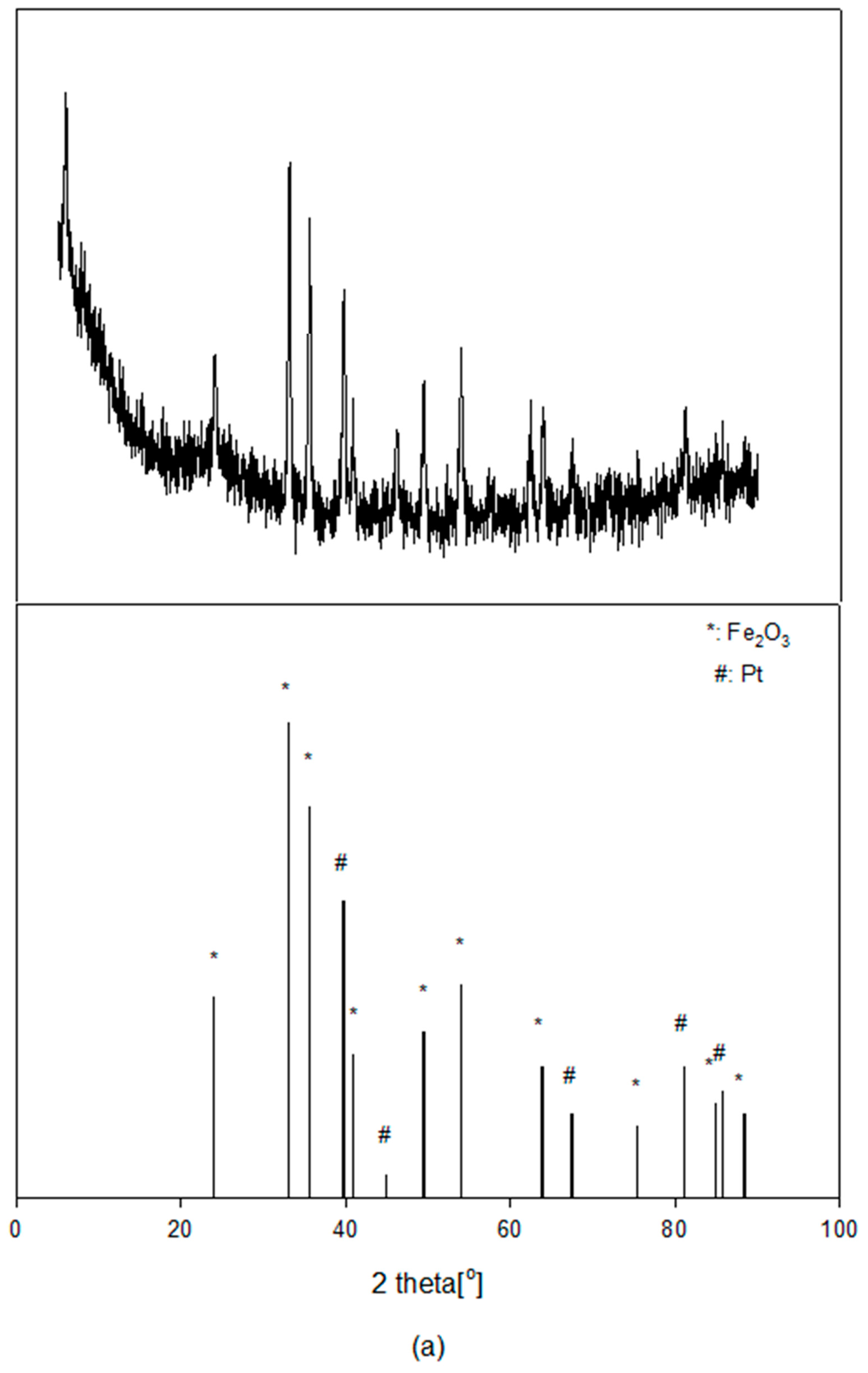
Figure 5 shows the XRD patterns of Pt(1)-Fe(30)/MCM-41 and Fe(30)/MCM-41 catalysts before reaction. Characteristic peaks of typical hexagonal Fe2O3 at 2θ = 24.13°, 33.10°, 35.63°, 40.83°, 49.42°, 53.98°, 63.99°, 75.44°, 84.89°, and 88.48° and those of cubic Pt at 2θ = 39.74°, 46.22°, 67.43°, 81.22°, and 85.66° were observed. However, the crystal phases of metals such as Fe, FeO, PtO, and PtO2, and the characteristic peaks of dissimilar metals, such as PtFe, were not observed. Only in the crystalline phase did fine nano-sized particles of Fe2O3 and Pt metal appear.
These behaviors suggested that the fine nano-sized Fe and Pt particles created by appropriate metal–carrier interactions were well dispersed in the MCM-41 carrier [8], and most Fe species in fresh Pt(1)-Fe(30)/MCM-41 were present as Fe2O3 crystallite. This was also consistent with FESEM and EDS results.
Figure 6 shows the XPS spectra of Pt(1)-Fe(30)/MCM-41 and Fe(30)/MCM-41 at the core electron levels of (a) Pt4f, (b) Fe2p, (c) O1s, and (d) Si2p before reaction. Characteristic Pt4f7/2 peaks appeared at 71.28, 72.68, and 74.68 eV, while those of Pt4f5/2 appeared at 74.88, 76.28, and 78.08 eV. These characteristic peaks were Pt0, Pt2+, and Pt4+, respectively. The characteristic peaks of Fe2p3/2, namely Fe0, Fe2+, and Fe3+, appeared at 709.58, 710.78, and 713.18 eV, respectively. The Fe2+ satellite peak of Fe2p3/2 appeared at 719.18 eV. Characteristic peaks of Fe2p1/2, namely Fe0, Fe2+, and Fe3+, appeared at 722.68, 724.28, and 726.78 eV, respectively. The Fe2+ satellite peak of Fe2p1/2 appeared at 723.38 eV. It was demonstrated that the satellite peaks of Fe2p3/2 and Fe2p1/2 stem from the combination of iron oxide and nanoparticles of Fe2O3 and FeO [41]. The Fe2p intensity of Pt(1)-Fe(30)/MCM-41 was higher than that of Fe(30)/MCM-41. There was no change in the Fe2p3/2 core electron levels of Pt(1)-Fe(30)/MCM-41, but the Fe2p1/2 core electron levels of Fe0 and Fe2+ chemically shifted to lower energies (0.2 eV and 0.1 eV, respectively) than those of the Fe(30)/MCM-41. Characteristic peaks of O1s appeared at 529.88 and 533.18 eV, corresponding to O2− and O−, respectively. The O1s intensity of Pt(1)-Fe(30)/MCM-41 was lower than that of Fe(30)/MCM-41. However, the core electron levels of O1s chemically shifted slightly to higher energy levels. Characteristic peaks of Si2p3/2 and Si2p1/2 appeared at 103.78 and 104.38 eV, respectively, corresponding to Si4+. The Si2p intensity of Pt(1)-Fe(30)/MCM-41 was lower than that of Fe(30)/MCM-41, but the core electron levels of Si2p also chemically shifted slightly to a higher energy. It was concluded that Fe ions of Pt(1)-Fe(30)/MCM-41 are more easily reduced than those in Fe(30)/MCM-41 as electrons move from Fe ions to O or Si atoms; this is due to the spillover effect of hydrogen. Table 1 shows that when 1 wt% of Pt was added to the Fe(30)/MCM-41 catalyst, the atomic percentage of Fe2p on the catalyst surface increased from 13.39% to 16.14% owing to the synergistic effect of Fe and Pt with appropriate metal–support interaction; however, the atomic percentage of Si2p decreased from 86.6% to 82.34%. It can be inferred that Fe and Pt interact with the lattice oxygen of MCM-41 to create FeO, Fe2O3, PtO, and PtO2 compounds, thereby changing the lattice constant of the catalyst and causing a synergistic effect between Pt, Fe, and MCM-41 as a result of appropriate metal–support interaction. Damyanova et al. [8] reported that adding 0.5 wt% of Pd to Ni/MCM-41 creates small nano-sized Ni particles, easily reduces NiO particles, and improves the dispersion of nickel particles on the catalyst surface. Karimi et al. [18] showed that the presence of Pt on the catalyst promotes the reduction degree of Ni and the dispersion of Ni on the carrier through a distinct spillover effect of H2.
Figure 7 shows the FESEM images, and mapping as well as the EDS characteristic peaks of the Pt(1)-Fe(30)/MCM-41 and Fe(30)/MCM-41 catalysts. The presence of Fe, Pt, Si, and O nanoparticles on the catalyst surface was confirmed. The average particle size of Fe was about 58.5 nm for the Fe(30)/MCM-41 and about 33.4 nm for Pt(1)-Fe(30)/MCM-41. The particle size of the catalyst surface of the Pt(1)-Fe(30)/MCM-41 catalyst was found to be 1.8 times smaller than that of the Fe(30)/MCM-41 catalyst, and the spherical particles were uniformly distributed. It can be assumed that the addition of 1 wt% of Pt to Fe(30)/MCM-41 creates much smaller nano-sized iron particles, resulting in a higher dispersion on the MCM-41 surface due to the suitable metal–carrier interaction (SMCI) [12], which means that catalysis is enhanced when Pt, Fe metal nanoparticles supported on the surface of MCM-41 are properly chemically bonded to the carrier.
2.3. Characterization of Carbon Deposited on the Catalyst
Figure 8 shows the XRD patterns of the Pt(1)-Fe(30)/MCM-41 post-reaction. The lattice planes of the C(002) at 2θ = 26.30° and the C(101) at 2θ = 43.25° are attributed to the growth of graphitic-like structures [43], which are attributable to the presence of filamentous carbon. Additionally, the diffraction peaks at 2θ = 45.00°, 50.01°, and 64.99° are assigned to Fe3C. It is assumed that some Fe particles gradually react with carbon to generate Fe3C during CDM. Awadallah et al. [7] reported that Fe2O3 in the catalyst would be reduced stepwise with CDM in the following order: Fe2O3 → Fe3O4 → FeO → Fe and Fe3C. The intensity ratio of C(101)/C (002) is attributable to the order of graphitic layers in the carbonaceous materials [44]. A lower ratio (C(101)/C(002) = 0.64) indicates a higher order of the structure. Moreover, after the reaction, the Pt(1)-Fe(30)/MCM-41 catalyst generated a strong and intense (002) diffraction peak. This suggests that CNT production is more active and that there are fewer defects in the CNT structure [45]. Figure 9 shows the TEM images of the deposited carbon over the Pt(1)-Fe(30)/MCM-41 catalyst after CDM at 700 °C for 6.7 h. As shown in Figure 9a–d, the catalyst produced two kinds of carbon nanotubes: multiwalled CNTs(MWCNTs) and bamboo-shaped CNTs. This is attributed to the dissolution of carbon atoms into nanometal particles with diameters of 10~75 nm, which precipitate at the ends rear to generate the nanometal particles to grow filamentous carbon away from the catalyst surface, depending on the strength of the metal–support interaction [16]. It was found that noticeable nanometal particles were embedded into the tip of the nanotube, which had a tubular MWCNT structure with a hollow core diameter of 14.1 nm and a wall thickness of 7.8 nm, and 16 layers of graphene. Thus, it can be inferred that the growth of MWCNTs is due to a tip-growth mechanism [41,46], which involves the decomposition of Fe3C into Fe and carbon. It is believed that MWCNTs may be formed as supersaturated carbon dissolved in Fe or Pt nanoparticles located on the external surfaces of the MCM-41 carrier. The Raman spectra also provide useful information about the crystallinity and structural disorder of the carbon nanotubes.
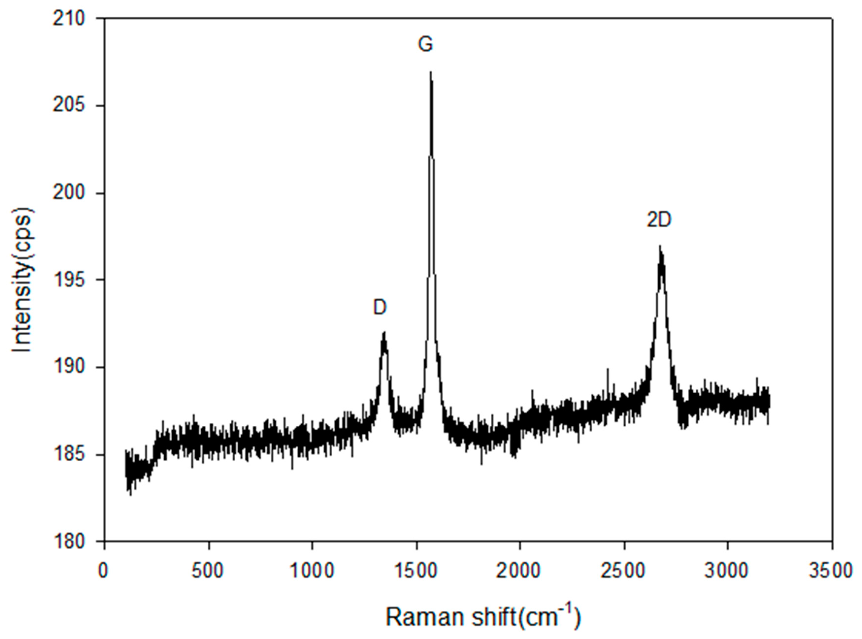
Figure 10 shows the Raman spectra of the as-produced MWCNTs after CDM over Pt(1)-Fe(30)/MCM-41 at 700 °C for 6.7 h. Three well-resolved Raman bands were observed for this catalyst. The bands observed at 1336 cm−1, 1568 cm−1, and 267 cm−1 in the Raman spectrum were named the D band, G band, and 2D (G′) band, respectively. The D band at 1336 cm−1 was attributed to the D band of the sp2 carbon material and was a result of the carbon disorder, which caused wall defects and lattice distortions in the carbon structures [47]. The G band at 1568 cm−1 was assigned to the crystalline graphitic carbon [48]. The 2D (G′) band at 2678 cm−1 was due to a second-order two-phonon process related to the formation of graphene layers. The intensity of the G band and 2D band confirmed the formation of multi-layer graphene sheets. An intense 2D band was observed for the disordered carbon nanomaterials [49]. Additionally, the ID/IG ratio intensity provided valuable information about the crystallinity as well as the graphitization degree of the CNTs [50]. With an ID/IG ratio of (Figure 10), it is evident that the Pt(1)-Fe(30)/MCM-41 catalyst produces MWCNTs with a high degree of crystallinity and graphitization.
3. Materials and Methods
3.1. Catalyst Preparation
The reagent used to prepare the catalyst was a special reagent with 99.999% purity from Sigma-Aldrich (St. Louis, MO, USA) products. The Pt(1)-Fe(30)/MCM-41 catalyst was prepared using the following standard support method (the numbers in parentheses indicate the percentage of weight carried). Following the dissolution of 0.002 g, 0.295 g, and 0.124 g of Pt(NO3)2·H2O (Sigma-Aldrich, St. Louis, MO, USA) and Fe(NO3)3·9H2O (Sigma-Aldrich, St. Louis, MO, USA), Ni(NO3)2·6H2O (Sigma-Aldrich, St. Louis, MO, USA), respectively, in ethanol, the reactor was filled with 0.1 g of MCM-41 (Sigma-Aldrich, St. Louis, MO, USA) carrier, which is a mesoporous material with a hierarchical structure from a family of aluminosilicate and silicate solids, and it was mixed uniformly with a stirrer for 5 h. The obtained precipitate was filtered and dried in a dryer at 100 °C for 24 h. The dried sample was calcined at 773 K for 5 h in an electric furnace (Eyela, TMF-1000) to create the Pt(1)-Fe(30)/MCM-41, Fe(30)/MCM-41, Pt(1)-Ni(20)/MCM-41, Ni(20)/MCM-41, and Pt(1)/MCM-41 catalysts, and the calcined sample was ground through a 150–200 mesh for use.
3.2. Catalyst Characterization
The XRD data were obtained using a Panalytical (Malvern, UK) Empyrean 3D high-resolution X-ray diffractometer (Cu Kα radiation, λ = 1.5419 Å; 40 kV, 30 mA). The XPS spectra were obtained with Alkα X-rays in operating conditions of 1 × 10 −9 mbar and 1.75 keV using an HP-X-ray photoelectron spectrometer (Thermo Scientific (Waltham, MA, USA) K-Alpha+). FESEM images and mapping images were obtained using a Zeiss Sigma (Livonia, MI, USA) 500 model field emission scanning microscope, and the chemical composition of the catalyst was analyzed using an EDS detector(Livonia, MI, USA). FETEM images were obtained using Jeol Jem-2100F at an acceleration voltage of 200 kV. Raman spectra were obtained using a Lazer Raman spectrophotometer (NRS-5100, Jasco, Oklahoma City, OK, USA).
3.3. Catalyst Performance
The catalytic reaction was performed using a fixed-bed flow reactor under atmospheric pressure. About 0.05 g of powdered catalyst was placed on the quartz cotton in the reactor, using a quartz reactor with an internal diameter of 10 mm and a length of 0.3 m. Subsequently, pure methane was supplied to the reactor at a gas hourly space velocity (GHSV) of 4.2 × 10⁴ CH4 mL/gcat.·h under reaction conditions of 973 K and 1 atm. Using a PID controller, the temperature of the reactor was controlled within ±1 K by placing a K-type thermocouple on the catalyst in the reactor. After purging the reactant using a pressure gauge attached to each cylinder, the composition of the reactant was controlled using a mass flow meter. The product was analyzed using TCD with a molecular sieve 5 A column connected to the GC (Shimadzu Co., Model 14B, Kyoto, Japan). The catalyst was employed by reducing the hydrogen temperature to 773 K for 5 h at a flow rate of 20 mL/min before the reaction, and then increasing the reaction temperature at a rate of 283 K/min. The CH4 conversion and H2 yield of each catalyst were calculated according to the following equation:
4. Conclusions
The CDM reaction was performed with Pt(1)-Fe(30)/MCM-41 and Fe(30)/MCM-41 catalysts using a fixed-bed flow reactor under atmosphere to investigate the methane conversion and the yield of hydrogen and CNTs. The addition of 1 wt% Pt promoter to Ni(20)/MCM-41 had no significant effect on the methane conversion and hydrogen yield of CDM, but had a significant effect on Fe(30)/MCM-41. The hydrogen yield of Pt(1)-Fe(30)/MCM-41 was 3.2 times higher than that of Fe(30)/MCM-41. The fine nano-sized Fe and Pt particles created by appropriate metal–carrier interactions of the Pt(1)-Fe(30)/MCM-41 and Fe(30)/MCM-41 catalyst were dispersed well in the MCM-41 carrier, and most Fe species in fresh Pt(1)-Fe(30)/MCM-41 were present as Fe2O3 crystallite. The addition of 1 wt% Pt to the Fe(30)/MCM-41 catalyst also increased the atomic percentage of Fe2p, which increased from 13.39% to 16.14%, and the Fe2p1/2 core electron levels of Fe0 and Fe2+ chemically shifted to lower energies (0.2 eV and 0.1 eV, respectively) than those of Fe(30)/MCM-41. Accordingly, Fe ions of Pt(1)-Fe(30)/MCM-41 are more easily reduced than those in Fe(30)/MCM-41. The Fe, Pt, Si, and O nanoparticles were uniformly distributed on the surface of the Pt(1)-Fe(30)/MCM-41 and Fe(30)/MCM-41 catalyst. The Pt(1)-Fe(30)/MCM-41 also created 1.8 times smaller nano-sized iron particles than those of the Fe(30)/MCM-41 catalyst, resulting in a higher dispersion on the MCM-41 surface due to the suitable metal–carrier interaction. The Pt(1)-Fe(30)/MCM-41 produced multiwalled and bamboo-shaped CNTs with high crystallinity and graphitization degrees using the tip-growth mechanism, with an ID/IG ratio of 0.93 and a C(101)/C(002) ratio of 0.64.
Funding
This research received no external funding.
Data Availability Statement
Data are contained within the article.
Conflicts of Interest
The authors declare no conflicts of interest.
References
- Abbas, H.F.; Daud, W.M.A.W. Hydrogen production by methane decomposition: A review. Int. J. Hydrogen Energy 2010, 35, 1160–1190. [Google Scholar] [CrossRef]
- Ashik, U.P.M.; Wan Daud, W.M.A.; Hayashi, J.-I. A review on methane transformation to hydrogen and nanocarbon: Relevance of catalyst characteristics and experimental parameters on yield. Renew. Sustain. Energy Rev. 2017, 76, 743–767. [Google Scholar] [CrossRef]
- Surendran, S.; Pathan, M.; Walke, P.; Syam, K.R.; Babu, P.G.; Poojary, N.; Sharma, R. Green synthesis and characterization of multiwall carbon nanotubes from sugarcane bagasse as a biogenic catalyst via chemical vapour deposition method using LPG as hydrocarbon source. Mater. Lett. 2024, 359, 135904–135908. [Google Scholar] [CrossRef]
- Torres, D.; Pinilla, J.L.; Lázaro, M.J.; Moliner, R.; Suelves, I. Hydrogen and multiwall carbon nanotubes production by catalytic decomposition of methane: Thermogravimetric analysis and scaling-up of FeeMo catalysts. Int. J. Hydrogen Energy 2014, 39, 3698–3709. [Google Scholar] [CrossRef]
- Otsuka, K.; Takenaka, S.; Ohtsuki, H. Production of pure hydrogen by cyclic decomposition of methane and oxidative elimination of carbon nanofibers on supported-Ni-based catalysts. Appl. Catal. A 2004, 273, 113–124. [Google Scholar] [CrossRef]
- Yao, Y.; Liu, X.; Hildebrandt, D.; Glasser, D. Fisher-Tropsch Synthesis Using H2/CO/CO2 Syngas Mixtures over an Iron Catalyst. Ind. Eng. Chem. Res. 2011, 50, 11002–11012. [Google Scholar] [CrossRef]
- Awadallah, A.E.; Aboul-Enein, A.A.; El-Desouki, D.S.; Aboul-Gheit, A.K. Catalytic thermal decomposition of methane to COx-free hydrogen and carbon nanotubes over MgO supported Bimetallic group VIII catalysts. Appl. Surf. Sci. 2014, 96, 100–107. [Google Scholar] [CrossRef]
- Zhao, R.; Du, X.; Cao, K.; Gong, M.; Li, Y.; Ai, J.; Ye, R.; Chen, R.; Shan, B. Highly dispersed Fe-decorated Ni nanoparticles prepared by atomic layer deposition for dry reforming of methane. Int. J. Hydrogen Energy 2023, 48, 28780–28791. [Google Scholar] [CrossRef]
- Zhao, Y.; Yuan, S.; Deng, J.; Li, C.; Feng, Y.; Xie, X.; Li, N. Investigation on carbon deposition deactivation of Fe-Ni-Ca/Al2O3catalyst under volatiles reforming of biomass pyrolysis. J. Anal. Appl. Pyrolysis 2022, 168, 105778–105791. [Google Scholar] [CrossRef]
- Estephane, J.; Aouad, S.; Hany, S.; El Khoury, B.; Gennequin, C.; El Zakhem, H.; El Nakat, J.; Aboukaȉs, A.; Abi Aad, E. CO2 reforming of methane over NieCo/ZSM5 catalysts. Aging and carbon deposition study. Int. J. Hydrogen Energy 2015, 40, 9201–9208. [Google Scholar] [CrossRef]
- Ȍzdemir, H.; Ȍksȕzȍmer, M.A.F.; Gȕrkaynak, M.A. Preparation and characterization of Ni based catalysts for thecatalytic partial oxidation of methane: Effect of supportbasicity on H2/CO ratio and carbon deposition. Int. J. Hydrogen Energy 2010, 35, 12147–12160. [Google Scholar] [CrossRef]
- Wua, H.; Liua, J.; Liu, H.; Hea, D. CO2 reforming of methane to syngas at high pressure over bi-component NiCo catalyst: The anti-carbon deposition and stability of catalyst. Fuel 2019, 235, 868–877. [Google Scholar] [CrossRef]
- Han, C.; Zhu, X.; Chen, B.; Wang, X. A strategy of constructing the Ni@silicalite-1 catalyst structure with highactivity and resistance to sintering and carbon deposition for dry reformingof methane. Fuel 2024, 355, 129548–129562. [Google Scholar] [CrossRef]
- Pashchenko, D.; Makarov, I. Carbon deposition in steam methane reforming over a Ni-basedcatalyst: Experimental and thermodynamic analysis. Energy 2021, 222, 119993–120002. [Google Scholar] [CrossRef]
- Damyanova, S.; Pawelec, B.; Arisshtirova, K.; Fierro, J.L.G.; Sener, C.; Dogu, T. MCM-41 supported PdNi catalysts for dry reforming of methane. Appl. Catal. B Environ. 2009, 92, 250–261. [Google Scholar] [CrossRef]
- Kutteri, D.A.; Wang, I.-W.; Samanta, A.; Li, L.; Hu, J. Methane decomposition to tip and base grown carbon nanotubes and COx-free H2 over mono- and bimetallic 3d transition metal catalysts. Catal. Sci. Technol. 2018, 8, 858–869. [Google Scholar] [CrossRef]
- Naikoo, G.A.; Arshad, F.; Hassan, I.U.; Tabook, M.A.; Pedram, M.Z.; Mustaqeem, M.; Tabassum, H.; Ahmed, W.; Rezakazemi, M. Thermocatalytic Hydrogen Production Through Decomposition of Methane—A Review. Front. Chem. 2021, 9, 736801–736824. [Google Scholar] [CrossRef]
- Pudukkudy, M.; Yaakob, Z.; Jia, Q.; Takriff, M.S. Catalytic decomposition of undiluted methane into hydrogen and Carbon nanotubes over Pt promoted Ni/CeO2 catalysts. N. J. Chem. 2018, 42, 14843–14856. [Google Scholar] [CrossRef]
- Karimi, S.; Bibak, F.; Meshkani, F.; Rastegarpanah, A.; Deng, J.; Liu, Y.; Dai, H. Promotional roles of second metals in catalyzing methane decomposition over the Ni-based catalysts for hydrogen production: A critical review. Int. J. Hydrogen Energy 2021, 46, 20435–20480. [Google Scholar] [CrossRef]
- Shah, N.; Panjala, D.; Huffman, G.P. Hydrogen Production by Catalytic Decomposition of Methane. Energy Fuels 2001, 15, 1528–1534. [Google Scholar] [CrossRef]
- Takenaka, S.; Shigeta, Y.; Tanabe, E.; Otsuka, K. Methane Decomposition into Carbon Nanofibers over Supported Pd-Ni Catalysts: Characterization of the Catalysts during the Reaction. J. Phys. Chem. B 2004, 108, 7656–7664. [Google Scholar] [CrossRef]
- Wang, G.; Jin, Y.; Liu, G.; Li, Y. Production of Hydrogen and Nanocarbon from Catalytic Decomposition of Methane over a Ni-Fe/Al2O3 Catalyst. Energy Fuels 2013, 27, 4448–4456. [Google Scholar] [CrossRef]
- Shen, Y.; Lua, A.C. Synthesis of Ni and Ni-Cu supported on carbon nanotubes for hydrogen and carbon production by catalytic decomposition of methane. Appl. Catal. B Environ. 2015, 164, 61–69. [Google Scholar] [CrossRef]
- Pudukudy, M.; Yaakob, Z.; Takriff, M.S. Methane decomposition over Pd promoted Ni/MgAl2O4 catalysts for the production of COx free hydrogen and multiwalled nanotubes. Appl. Surf. Sci. 2015, 356, 1320–1326. [Google Scholar] [CrossRef]
- Tezel, E.; Figen, H.E.; Baykara, S.Z. Hydrogen production by methane decomposition using bimetallic Ni-Fe catalysts. Int. J. Hydrogen Energy 2019, 44, 9930–9940. [Google Scholar] [CrossRef]
- Mesfera, M.K.A.; Danisha, M.; Shahb, M. Synthesis and optimization of hydrotalcite derived Ni-Fe-Cu basedcatalysts for catalytic methane decomposition process using the design ofexperiment approach. J. Taiwan Inst. Chem. Eng. 2021, 128, 370–379. [Google Scholar] [CrossRef]
- Wang, Y.; Zhang, Y.; Zhao, S.; Zhu, J.; Jin, L.; Hu, H. Preparation of bimetallic catalysts Ni-Co and Ni-Fe supported on activatedcarbon for methane decomposition. Carbon Resour. Convers. 2020, 3, 190–197. [Google Scholar] [CrossRef]
- Awadallah, A.E.; Aboul-Enein, A.A.; Deyab, M.A.; Azab, M.A.; Haggar, A.M. Impact of Cr doping on the performance of Ni/Al2O3 catalyst through methane decompositioninto COx-free hydrogen and carbon nanomaterials. Chem. Eng. Res. Des. 2022, 186, 701–712. [Google Scholar] [CrossRef]
- Sun, H.; Ren, S.; Ji, X.; Song, W.; Guo, Q.; Shen, B. Doping Fe and Zn to modulate Ni nanoparticles on IM-5 for methane decomposition to form hydrogenand CNTs. Int. J. Hydrogen Energy 2023, 48, 13081–13096. [Google Scholar] [CrossRef]
- Al-Fatesh, A.S.; Abdelkader, A.; Osman, A.I.; Lanre, M.S.; Fakeeha, A.H.; Alhoshan, M.; Alanazi, Y.M.; Awadallah, A.E.; Rooney, D.W. Non-supported bimetallic catalysts of Fe and Co for methane decomposition into H2 and a mixture of graphene nanosheets and carbon nanotubes. Int. J. Hydrogen Energy 2023, 48, 26506–26517. [Google Scholar] [CrossRef]
- Zhao, X.S.; Lu, G.Q.; Millar, G.J. Advances in Mesoporous Molecular Sieve MCM-41. Ind. Eng. Chem. Res. 1996, 35, 2075–2090. [Google Scholar] [CrossRef]
- Kiani, M.R.; Kamandi, R.; Nozarian, K.; Rahimpour, M.R. Introducing a novel catalyst for efficient conversion of CO2 into syngas through reverse-water-gas-shift (RWGS) reactions based on highly mesoporous structures MCM-41: Influence of the Fe incorporation. Energy Convers. Manag. 2024, 304, 118247–118263. [Google Scholar] [CrossRef]
- Lopez, L.; Montes, V.; Kušar, H.; Cabrera, S.; Boutonnet, M.; Järås, S. Syngas conversion to ethanol over a mesoporous Cu/MCM-41 catalyst: Effect of K and Fe promoters. Appl. Catal. A Gen. 2016, 526, 77–83. [Google Scholar] [CrossRef]
- Pawelec, B.; Damyanova, S.; Arishtirova, K.; Fierro, J.L.G.; Petrov, L. Structural and surface features of PtNi catalysts for reforming of methane with CO2. Appl. Catal. A Gen. 2007, 323, 188–201. [Google Scholar] [CrossRef]
- Hu, F.; Jin, C.; Lim, K.H.; Li, C.; Song, G.; Bella; Wang, T.; Ye, R.; Lu, Z.-H.; Feng, G.; et al. Promoting hydrogen spillover of NiFe/CeO2 catalyst with plasma-treatment for CO2 methanation. Fuel Process. Technol. 2023, 250, 107873–107884. [Google Scholar] [CrossRef]
- Vanoye, L.; Guicheret, B.; Rivera-Cárcamo, C.; Audevard, J.; Navarro-Ruiz, J.; del Rosal, I.; Gerber, I.C.; Campos, C.H.; Machado, B.F.; Volkman, J.; et al. Deactivation of Pd/C catalysts by irreversible loss of hydrogen spilloverability of the carbon support. J. Catal. 2023, 424, 173–188. [Google Scholar] [CrossRef]
- Li, M.; Yin, W.; Pan, J.; Zhu, Y.; Sun, N.; Zhang, X.; Wan, Y.; Luo, Z.; Yi, L.; Wang, L. Hydrogen spillover as a promising strategy for boosting heterogeneous catalysis and hydrogen storage. Chem. Eng. J. 2023, 471, 144691–144714. [Google Scholar] [CrossRef]
- Guo, J.-H.; Li, X.-D.; Cheng, X.-L.; Liu, H.-Y.; Li, S.-J.; Chen, G. The theoretical study of the bimetallic Ni/Pd, Ni/Pt and Pt/Pd catalysts for hydrogen spillover on penta-graphene. Int. J. Hydrogen Energy 2018, 43, 19121–19129. [Google Scholar] [CrossRef]
- Boudjahema, A.-G.; Bettahar, M.M. Effect of oxidative pre-treatment on hydrogen spillover for a Ni/SiO2catalyst. J. Mol. Catal. A Chem. 2017, 426, 190–197. [Google Scholar] [CrossRef]
- Ai, Q.; Yuan, Z.; Huang, R.; Yang, C.; Jiang, G.; Xiong, J.; Huang, Z.; Yuan, S. One-pot co-precipitation synthesis of Fe3O4 nanoparticles embedded in 3D carbonaceous matrix as anode for lithium ion batteries. J. Mater. Sci. 2019, 54, 4212–4224. [Google Scholar] [CrossRef]
- Chen, X.; Pang, X.; Fauteux-Lefebvre, C. The base versus tip growth mode of carbon nanotubes by catalytic hydrocarbon cracking: Review, challenges and opportunities. Carbon Trends 2023, 12, 100273–100289. [Google Scholar] [CrossRef]
- Seo, H.J. Effect of Pt as a Promoter in Decomposition of CH4 to Hydrogen over Pt(1)-Fe(30)/MCM-41 catalyst. Appl. Chem. Eng. 2023, 4, 674–678. [Google Scholar]
- Zhu, W.Z.; Miser, D.E.; Chan, W.G.; Hajaligol, M.R. Characterization of multiwalled carbon nanotubes prepared by carbon arc cathode deposit. Mater. Chem. Phys. 2003, 82, 638–647. [Google Scholar] [CrossRef]
- Serrano, D.P.; Botas, J.A.; Fierro, J.L.G.; Guil-Lŏpez, R.; Pizarro, P.; Gŏmez, G. Hydrogen production by methane decomposition: Origin of the catalytic activity of carbon materials. Fuel 2010, 89, 1241–1248. [Google Scholar] [CrossRef]
- Chen, Y.; Riu, D.-H.; Lim, Y.-S. Carbon nanotubes grown over Fe-Mo-Mg-O composite catalysts. Met. Mater. Int. 2008, 14, 385–390. [Google Scholar] [CrossRef]
- Gohier, A.; Ewels, C.P.; Minea, T.M.; Djouadi, M.A. Carbon nanotube growth mechanism switches from tip- to base-growth with decreasing catalyst particle size. Carbon 2008, 46, 1331–1338. [Google Scholar] [CrossRef]
- AL-Fatesh, A.S.; Amin, A.; Ibrahim, A.A.; Khan, W.U.; Soliman, M.A.; AL-Otaibi, R.L.; Fakeeha, A.H. Effect of Ce and Co Addition to Fe/Al2O3 for Catalytic Methane Decomposition. Catalysts 2016, 6, 40. [Google Scholar] [CrossRef]
- Ferrari, A.C. Raman spetroscopy of graphene and graphite: Disorder, electron-phonon coupling, doping and non-adiabatic effects. Solid State Commun. 2007, 143, 47–57. [Google Scholar] [CrossRef]
- Lespade, P.; Marchand, A.; Couzi, M.; Cruege, F. Caracterisation de materiaux carbones par microspectrometrie Raman. Carbon 1984, 22, 375–385. [Google Scholar] [CrossRef]
- Cheng, J.; Zhang, X.; Luo, Z.; Liu, F.; Ye, Y.; Yin, W.; Liu, W.; Han, Y. Carbon nanotube synthesis and parametric study using CaCO3 nanocrystals as catalyst support by CVD. Mater. Chem. Phys. 2006, 95, 5–11. [Google Scholar] [CrossRef]
Figure 1.
Conversion of CH4 obtained in methane decomposition over Pt(1)-Fe(30)/MCM-41, Pt(1)-Ni(20)/MCM-41, Fe(30)/MCM-41, Ni(20)/MCM-41, and Pt(1)/MCM-41 in the packed bed reactor: P = 1 atm, T = 700 °C, and GHSV = 4.2 × 10⁴ CH4 mL gcat.−1·h−1.
Figure 1.
Conversion of CH4 obtained in methane decomposition over Pt(1)-Fe(30)/MCM-41, Pt(1)-Ni(20)/MCM-41, Fe(30)/MCM-41, Ni(20)/MCM-41, and Pt(1)/MCM-41 in the packed bed reactor: P = 1 atm, T = 700 °C, and GHSV = 4.2 × 10⁴ CH4 mL gcat.−1·h−1.
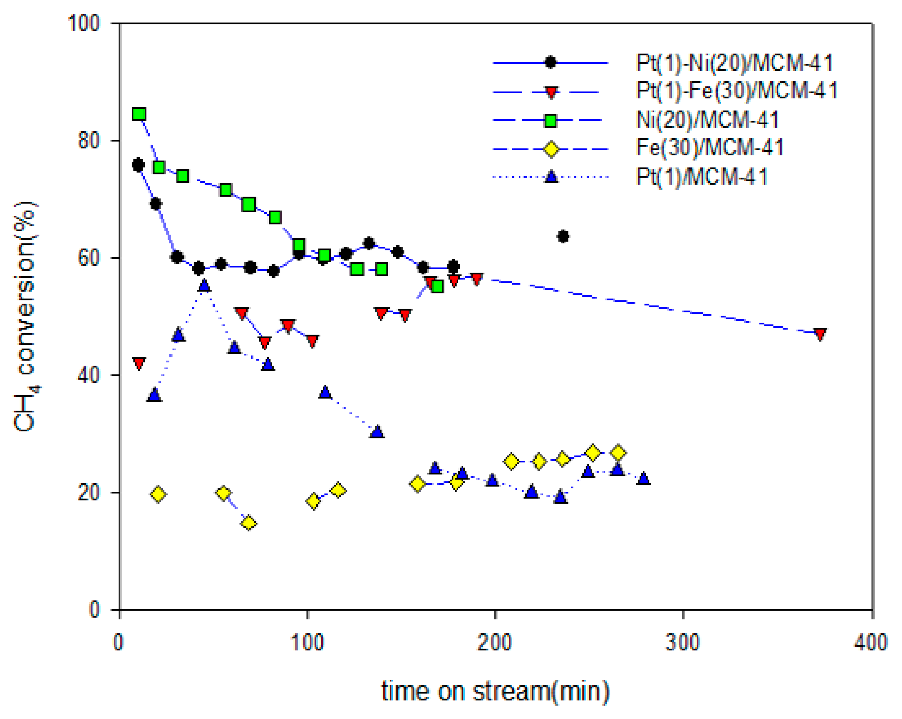
Figure 2.
Yield of H2 obtained in methane decomposition over Pt(1)-Fe(30)/MCM-41, Pt(1)-Ni(20)/MCM-41, Fe(30)/MCM-41, Ni(20)/MCM-41, and Pt(1)/MCM-41 in the packed bed reactor: P = 1 atm, T = 700 °C, and GHSV = 4.2 × 10⁴ CH4 mL gcat.−1·h−1.
Figure 2.
Yield of H2 obtained in methane decomposition over Pt(1)-Fe(30)/MCM-41, Pt(1)-Ni(20)/MCM-41, Fe(30)/MCM-41, Ni(20)/MCM-41, and Pt(1)/MCM-41 in the packed bed reactor: P = 1 atm, T = 700 °C, and GHSV = 4.2 × 10⁴ CH4 mL gcat.−1·h−1.
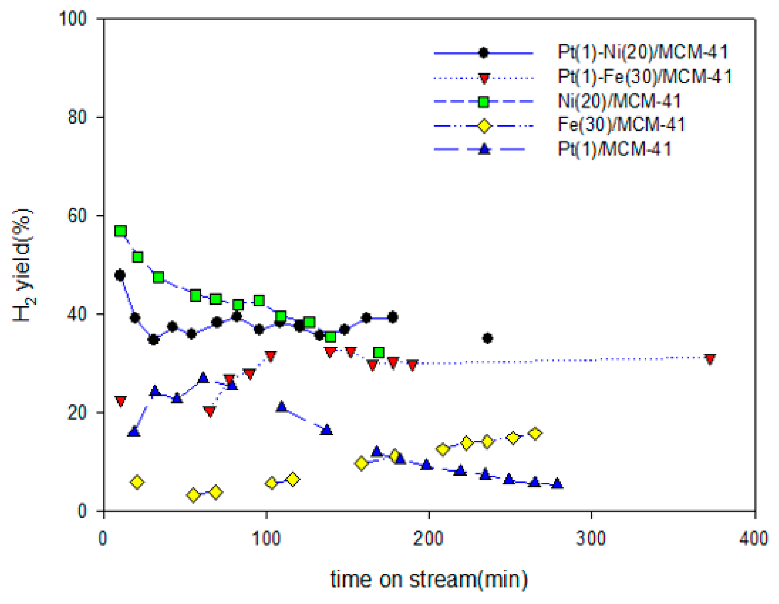
Figure 3.
CH4 conversion and H2 yield vs. reaction temperature obtained in methane decomposition over Pt(1)-Fe(30)/MCM-41 in the packed bed reactor: P = 1 atm and GHSV = 4.2 × 10⁴ CH4 mL gcat.−1·h−1.
Figure 3.
CH4 conversion and H2 yield vs. reaction temperature obtained in methane decomposition over Pt(1)-Fe(30)/MCM-41 in the packed bed reactor: P = 1 atm and GHSV = 4.2 × 10⁴ CH4 mL gcat.−1·h−1.

Figure 4.
CH4 conversion and H2 yield vs. GHSV obtained in methane decomposition over Pt(1)-Fe(30)/MCM-41 in the packed bed reactor: P = 1 atm and T = 700 °C.
Figure 4.
CH4 conversion and H2 yield vs. GHSV obtained in methane decomposition over Pt(1)-Fe(30)/MCM-41 in the packed bed reactor: P = 1 atm and T = 700 °C.

Figure 5.
XRD patterns of (a) fresh Pt(1)-Fe(30)/MCM-41 and (b) fresh Fe(30)/MCM-41 catalysts.

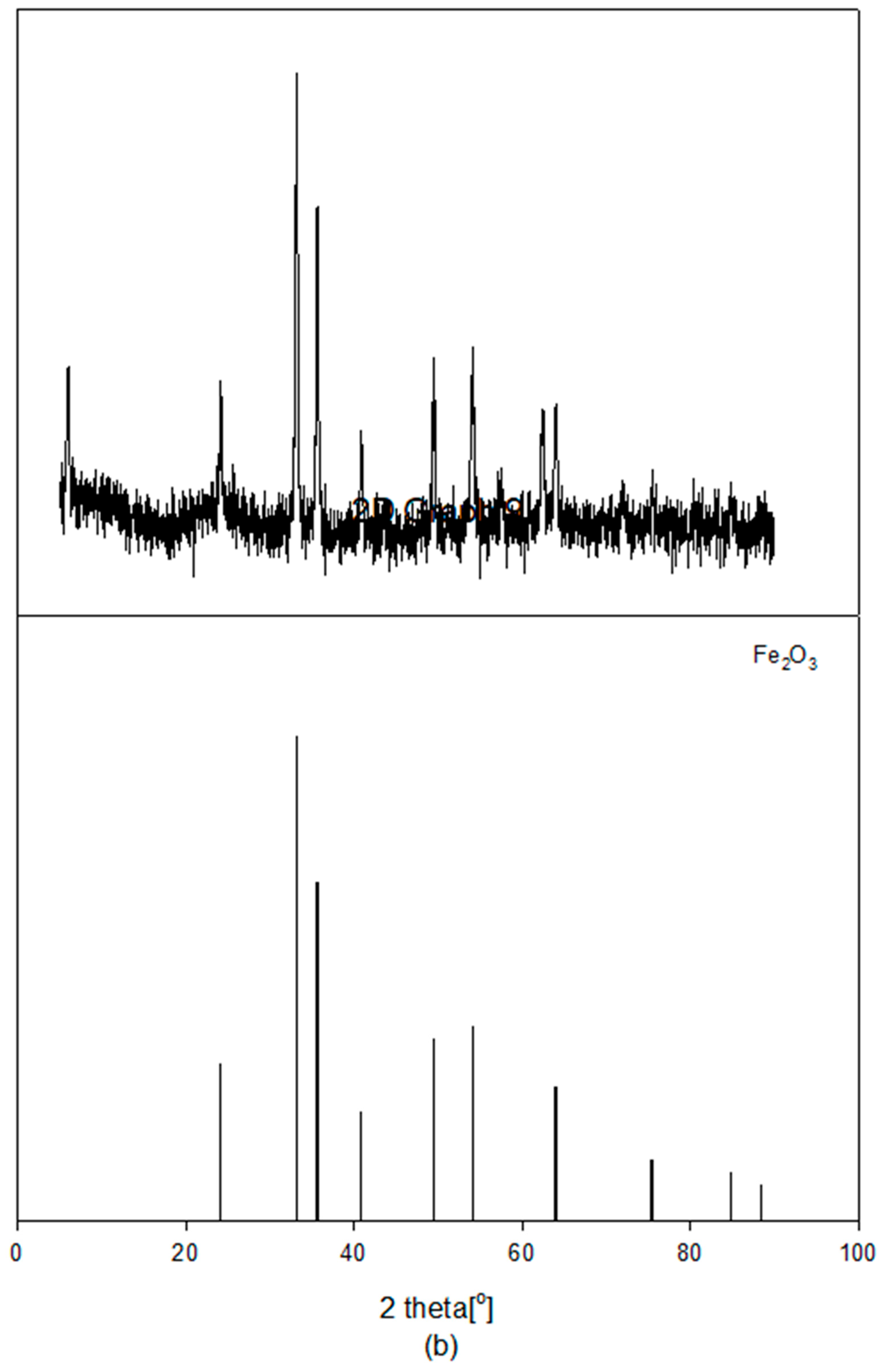
Figure 6.
XPS spectra of (a) Pt4f, (b) Fe2p, (c) O1s, and (d) Si2p core electron levels for fresh Pt(1)-Fe(30)/MCM-41 and Fe(30)/MCM-41 [42].
Figure 6.
XPS spectra of (a) Pt4f, (b) Fe2p, (c) O1s, and (d) Si2p core electron levels for fresh Pt(1)-Fe(30)/MCM-41 and Fe(30)/MCM-41 [42].


Figure 7.
(A) FESEM (Aa) image, (Ab) mapping, and (Ac) EDS characteristic peaks of fresh Pt(1)-Fe(30)/MCM-41 and (B) FESEM (Ba) image, (Bb) mapping, and (Bc) EDS characteristic peaks of fresh Fe(30)/MCM-41 [42].
Figure 7.
(A) FESEM (Aa) image, (Ab) mapping, and (Ac) EDS characteristic peaks of fresh Pt(1)-Fe(30)/MCM-41 and (B) FESEM (Ba) image, (Bb) mapping, and (Bc) EDS characteristic peaks of fresh Fe(30)/MCM-41 [42].
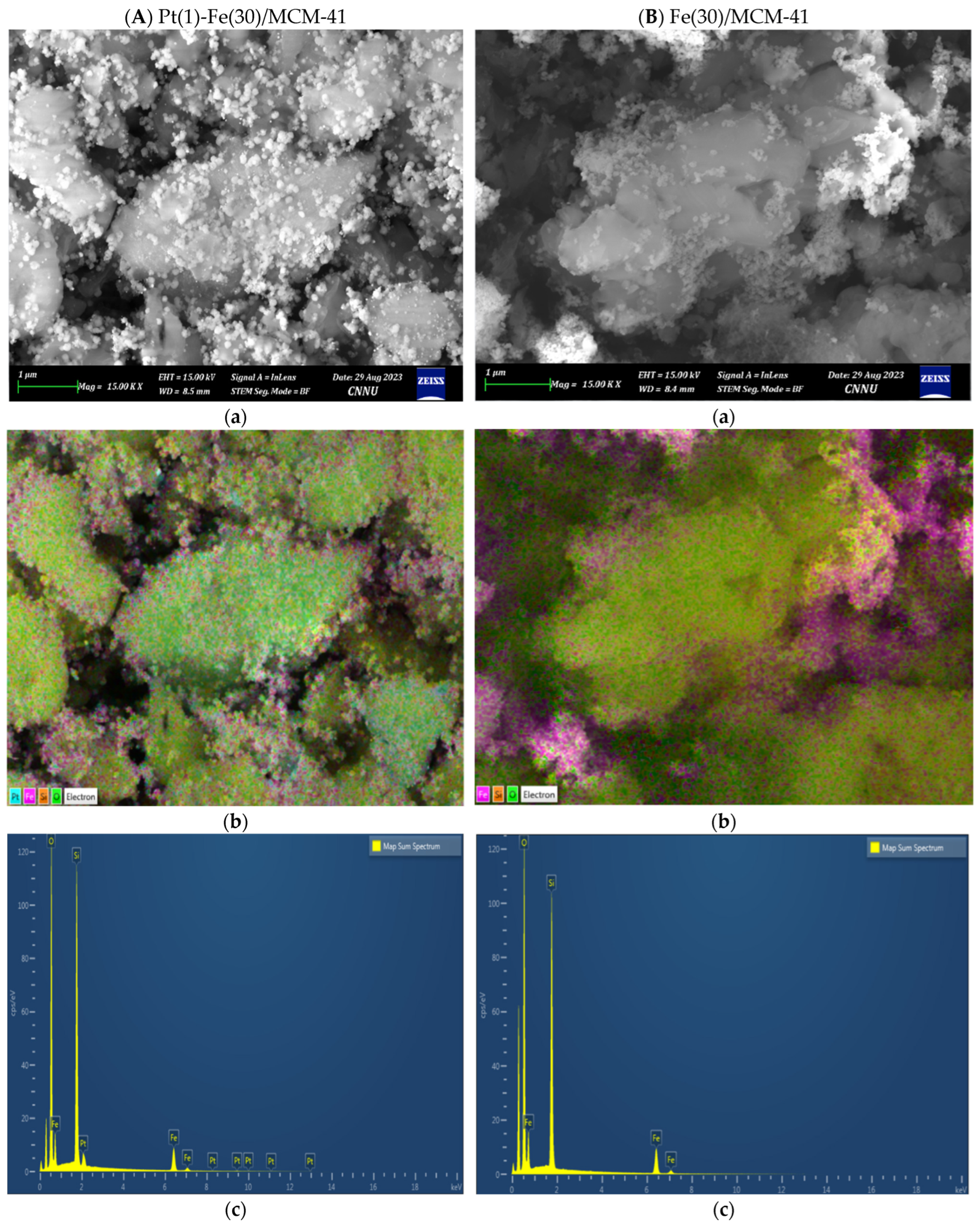
Figure 8.
XRD patterns of Pt(1)-Fe(30)/MCM-41 catalysts (a) before and (b) after the reaction.


Figure 9.
FETEM images at (a) 500 nm, (b) 200 nm, (c) 100 nm, and (d) 10 nm of Pt(1)-Fe(30)/MCM-41 after the reaction.
Figure 9.
FETEM images at (a) 500 nm, (b) 200 nm, (c) 100 nm, and (d) 10 nm of Pt(1)-Fe(30)/MCM-41 after the reaction.

Figure 10.
Raman spectra of Pt(1)−Fe(30)/MCM−41 after the reaction.


Table 1.
Atomic percentage of core electron levels for fresh Pt(1)-Fe(30)/MCM-41 and Fe(30)/MCM-41 according to XPS data [42].
Table 1.
Atomic percentage of core electron levels for fresh Pt(1)-Fe(30)/MCM-41 and Fe(30)/MCM-41 according to XPS data [42].
| Fresh Catalyst | Core Electron Levels | Atomic % |
|---|---|---|
| Pt(1)-Fe(30)/MCM-41 | Pt4f | 1.51 |
| Fe2p | 16.14 | |
| Si2p | 82.34 | |
| Fe(30)/MCM-41 | Fe2p | 13.39 |
| Si2p | 86.60 |
Disclaimer/Publisher’s Note: The statements, opinions and data contained in all publications are solely those of the individual author(s) and contributor(s) and not of MDPI and/or the editor(s). MDPI and/or the editor(s) disclaim responsibility for any injury to people or property resulting from any ideas, methods, instructions or products referred to in the content. |
© 2024 by the author. Licensee MDPI, Basel, Switzerland. This article is an open access article distributed under the terms and conditions of the Creative Commons Attribution (CC BY) license (https://creativecommons.org/licenses/by/4.0/).
Share and Cite
MDPI and ACS Style
Seo, H.J. Catalytic Decomposition of CH4 to Hydrogen and Carbon Nanotubes Using the Pt(1)-Fe(30)/MCM-41 Catalyst. Catalysts 2024, 14, 282. https://doi.org/10.3390/catal14040282
AMA Style
Seo HJ. Catalytic Decomposition of CH4 to Hydrogen and Carbon Nanotubes Using the Pt(1)-Fe(30)/MCM-41 Catalyst. Catalysts. 2024; 14(4):282. https://doi.org/10.3390/catal14040282
Chicago/Turabian StyleSeo, Ho Joon. 2024. "Catalytic Decomposition of CH4 to Hydrogen and Carbon Nanotubes Using the Pt(1)-Fe(30)/MCM-41 Catalyst" Catalysts 14, no. 4: 282. https://doi.org/10.3390/catal14040282
Note that from the first issue of 2016, this journal uses article numbers instead of page numbers. See further details here.