Review

Design of Pt/Carbon Xerogel Catalysts for PEM Fuel Cells

1
Laboratory of Chemical Engineering—Nanomaterials, Catalysis, Electrochemistry, University of Liège (B6a), B-4000 Liège, Belgium
2
College of Food Science and Engineering, Nanjing University of Finance and Economics, Nanjing 210046, China
*
Author to whom correspondence should be addressed.
Catalysts 2015, 5(1), 40-57; https://doi.org/10.3390/catal5010040
Submission received: 3 December 2014 / Accepted: 9 January 2015 / Published: 28 January 2015
(This article belongs to the Special Issue Electrocatalysis in Fuel Cells)

Abstract

:
The design of efficient catalytic layers of proton exchange membrane fuel cells (PEMFCs) requires the preparation of highly-loaded and highly-dispersed Pt/C catalysts. During the last few years, our work focused on the preparation of Pt/carbon xerogel electrocatalysts, starting from simple impregnation techniques that were further optimized via the strong electrostatic adsorption (SEA) method to reach high dispersion and a high metal weight fraction. The SEA method, which consists of the optimization of the precursor/support electrostatic impregnation through an adequate choice of the impregnation pH with regard to the support surface chemistry, leads to very well-dispersed Pt/C samples with a maximum 8 wt.% Pt after drying and reduction under H2. To increase the metal loading, the impregnation-drying-reduction cycle of the SEA method can be repeated several times, either with fresh Pt precursor solution or with the solution recycled from the previous cycle. In each case, a high dispersion (Pt particle size ~3 nm) is obtained. Finally, the procedure can be simplified by combination of the SEA technique with dry impregnation, leading to no Pt loss during the procedure.

1. Introduction

Pt supported on a high surface area carbon support is commonly used in low-temperature proton exchange membrane fuel cells (PEMFCs) to catalyze the oxidation of H2 at the anode and the reduction of O2 at the cathode [1]. The former is fast, thus allowing small Pt loading to be used at the anode. However, due to the sluggish O2 reduction kinetics, high Pt loading is required at the cathode. In addition, the thickness of both the cathode and the anode should be as small as possible to avoid diffusional limitations; this means that electrocatalysts with a high Pt mass fraction are required. In commercial Pt/carbon black catalysts, the Pt mass fraction may be increased up to 60 wt.% to cope with these limitations. However, the electrode structure does not guarantee that each Pt particle is active: indeed, to be electrochemically active, the Pt particles must be in contact with both the electrically-conductive carbon support and the membrane, which can be achieved only by reconstructing an ionomer network (Nafion®) within the porosity of the catalytic layer. In addition, mass transport of reactants and products within the catalytic layers should be easy: (i) the Pt particles must be accessible to the gas reactant, through the porous structure of the catalytic layer; (ii) protons have to circulate in the ionomer network and reach the membrane; (iii) electrons must be collected by the catalyst support and be driven to the current collector. In most cases, a non-negligible fraction of the Pt particles does not meet all of these requirements, which results in undesirable Pt waste.
To produce efficient electrocatalysts and, thus, decrease the mass of Pt used, significant efforts have been directed towards the synthesis. First, the size of the Pt particles should be appropriate: ~3-nm particles lead to the most active catalyst per mass unit of Pt [2]. Second, mass transport limitations can be decreased by using carbon supports with an appropriate pore texture. This is why research turns towards nanostructured carbons [3]. Finally, the distribution of the electron and the ion components (Pt/C and Nafion®) depends on the processing, which must be optimized. This optimization strongly depends on the support chosen and especially on its pore texture and surface chemistry.
For several years now, our group has been working on the development of new Pt/C electrocatalysts with high specific activity and a support nanostructure that allows for optimal mass transport. The supports studied are carbon xerogels, i.e., texture-controlled synthetic carbon materials prepared by drying and pyrolysis of resorcinol-formaldehyde aqueous gels [4]. Indeed, these supports proved to be excellent materials for heterogeneous catalysis in gas phase reactions [5]: since their pore texture can easily be tuned, from nm- to μm-sized pores, one can design the catalyst support in order to decrease the mass-transport limitations. The same idea was then applied to other catalytic systems, i.e., PEMFCs [6,7,8]. Since the pore texture and surface chemistry are fully adjustable, one can design the support in order to: (i) improve Pt dispersion; (ii) improve mass transport in the operating conditions; and (iii) improve the Pt-Nafion contact, so as to reach 100% Pt particle utilization, i.e., a configuration in which each Pt particle is electroactive for the oxygen reduction reaction.
One of the objectives of our studies is to rationalize the synthesis procedure, so as to keep it as simple and inexpensive as possible. The metal deposition was first performed by simple wet impregnation, followed by reduction under hydrogen [9]. However, the excellent metal dispersion (particle size ~2 nm) obtained at low Pt loading could not be maintained at a high metal weight percentage [6]. The impregnation was thus studied in depth, with attention paid to the metal precursor-support interactions, to design new procedures allowing for high Pt dispersion and high Pt weight percentage. The synthesis techniques had to remain as simple as possible to: (i) make their industrial scale-up possible; and (ii) avoid metal losses during preparation. The present article consists thus of a review of the different procedures investigated during the last few years in our research group. Its aim is to clearly depict the reasoning leading to optimized procedures and to sum up the results obtained at each step. The properties of the catalysts, as well as the pros and cons of each synthesis technique are described and compared. Finally, the goal of this paper is to open new synthesis routes that will allow for the easy production of new supported metal catalysts with high loading and high dispersion.

2. Synthesis Techniques
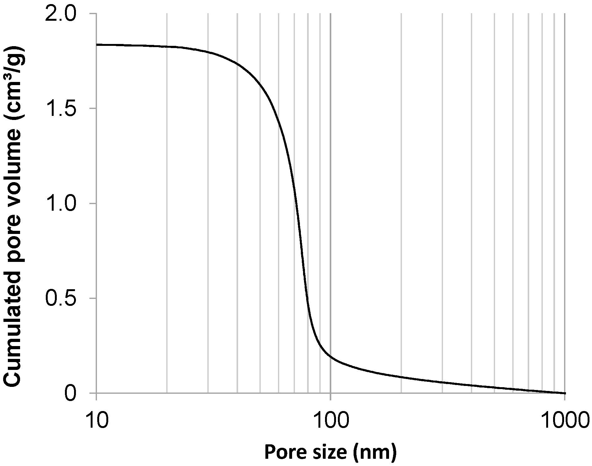
2.1. Carbon Support

In all cases, the support was a carbon xerogel prepared following a well-known method [4]. In the present work, the carbon xerogel chosen was a material with a specific surface area of ~600 m2/g and a total pore volume of ~2.1 cm3/g (micropore volume ~0.23 cm3/g), and the average meso-macropore size was ~70 nm (Figure 1). These properties were measured by coupling nitrogen adsorption to mercury porosimetry, following a method fully described elsewhere [4].
Figure 1. Cumulative pore volume vs. pore size of the carbon xerogel support (micropores excluded) calculated from Hg porosimetry data.
Catalysts 05 00040 g001
Briefly, the gel was obtained by polycondensation of resorcinol with formaldehyde in water. The resorcinol/formaldehyde molar ratio, R/F, was fixed at 0.5; the resorcinol/sodium carbonate molar ratio, R/C, was chosen to be equal to 1000; and the dilution ratio, D, i.e., the solvent/(resorcinol and formaldehyde) molar ratio, was set at 5.7. The resorcinol, formaldehyde, sodium carbonate and water amounts can be found in [4]. The sealed flask was put in an oven at 358 K for gelling and aging for 72 h, then the obtained gel was dried under vacuum, first at 333 K under decreasing pressure (stepwise, from atmospheric pressure down to 103 Pa, 8 h), second at 423 K and 103 Pa for 12 h. When the sample was dry, it was pyrolyzed at 1073 K under nitrogen flow following a procedure described in another study [4]. After pyrolysis, the xerogel was crushed into a fine powder.

2.2. Wet Impregnation

Pt/carbon xerogel catalysts can be obtained by simple wet impregnation (WI) [9]. One catalyst was prepared by soaking the solid in an H2PtCl6 aqueous solution with the appropriate concentration, calculated with regard to the target Pt loading; in this case, one supposes: (i) that all of the metal entering the support porosity remains trapped after drying; and (ii) that no interaction exists between the support and the Pt precursor. Therefore, with the total pore volume equal to 2.1 cm3/g, one calculates that, to obtain a 1-wt.% Pt/C catalyst, the impregnation suspension should contain, for 1 g of carbon support, 0.64 cm3 of H2PtCl6·6H2O solution (100 g/L) and 4.36 mL of deionized water [9]. The nominal Pt weight percentage, Ptth, i.e., the Pt mass fraction calculated from the two above-mentioned assumptions, is equal to 1 wt.%. The maximum Pt weight percentage, Ptmax, i.e., the value reached should all the Pt present in the solution be deposited on the carbon support, equals 2.4 wt.% [9]. The carbon support was simply soaked in the precursor aqueous solution under magnetic stirring for 1 h, at ambient temperature. After impregnation, the excess of solution was removed by filtration. The catalyst was dried under ambient air for 24 h, then under vacuum (103 Pa), at 333 K, for another 12 h. The sample was finally reduced under hydrogen flow (0.025 mmol/s) for 3 h at 623 K (heating rate: 350 K/h).
The sample prepared by the wet impregnation technique described in the present section is labelled “WI” (for “wet impregnation”).

2.3. Wet Impregnation Coupled to Liquid Phase Reduction

To reach much higher Pt weight percentages, which is undoubtedly necessary for PEMFC applications, one option is to use a precursor solution with high Pt precursor concentration and to reduce the metal directly on the solid by the addition of a reductant in the liquid phase (e.g., NaBH4) [6]. In this case, all of the Pt present in the solution is supposed to be reduced on the support.
The nominal Pt weight percentage, Ptth, was chosen equal to 35 wt.% Pt. The ground carbon xerogel (1 g) was suspended in an H2PtCl6 aqueous solution (0.6 gPt/L) for 1 h, at ambient temperature, under magnetic stirring. At the beginning of the impregnation, the pH of the solution was always about 2.2, due to the acidity of H2PtCl6. After 24 h of magnetic stirring, NaBH4 was added to reduce the Pt ionic precursor into metallic Pt. A very large excess of NaBH4 (several times the stoichiometric quantity required to reduce the total amount of Pt salt) was used for this; indeed, under these conditions, water is reduced into H2, and this side-reaction competes with the Pt reduction process. The catalyst sample was washed thoroughly with boiling water. After filtration, the samples was dried in open air at 333 K during 12 h. Finally, the catalyst was reduced in flowing H2 (0.025 mmol/s) during 3 h at 623 K to ensure the transformation of the last platinum ions into the metallic Pt.
The sample obtained by this technique is labeled “WI-R” (for “wet impregnation-reduction”).

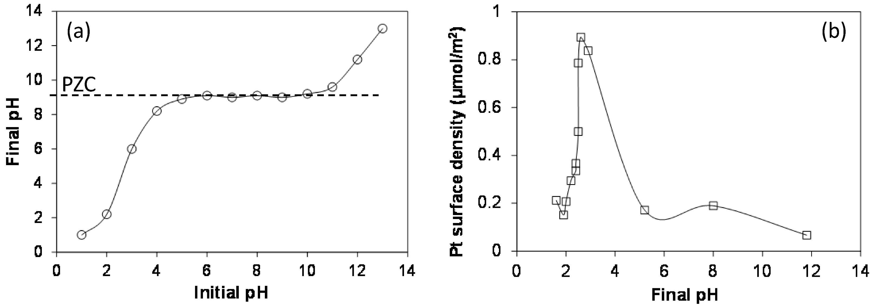
2.4. Strong Electrostatic Adsorption

The study of the WI technique shows that interactions exist between the support and the precursor: the amount of Pt deposited on the carbon xerogel is higher than expected [9]. This is due to the electrostatic attraction between the support and the precursor. This effect can be exploited to reach a high Pt weight percentage. Indeed, the electrostatic interactions can be emphasized by choosing an adequate pH of impregnation. This is the principle of the strong electrostatic adsorption technique, inspired from the early work of Brunelle et al. [10], who postulated that the adsorption of noble metal complexes onto common oxide supports was essentially Coulombic in nature. Rational synthesis techniques were then developed by Regalbuto et al. [11,12], initially to deposit Pt and Pd nanoparticles on inorganic supports. The technique is, however, quite versatile: it was adapted to various supports, like silica [13,14], alumina [15] and carbon [16,17], and can be extended to other metals and to bimetallic nanoparticles [18,19].
The point of zero charge (PZC) of a support corresponds to the pH value at which the electric charge density on the support surface is zero (neutral surface). At a pH lower than its PZC, the support charges positively and adsorbs preferentially anions (e.g., PtCl62−). On the contrary, at a pH higher than the PZC of the support, the adsorption of cations (e.g., [Pt(NH3)4]2+) is enhanced. This property can be exploited by the so-called “strong electrostatic adsorption” (SEA) method [11,20], which consists of maximizing the electrostatic interactions, so as to adsorb the maximum amount of Pt at the support surface. The PZC of the support can be measured by the method of Park and Regalbuto (equilibrium pH at high loading, EpHL) [11]. Briefly, the porous solid was soaked in water solutions of various initial pH, and after stabilization, the pH was measured again. The PZC value corresponds to a plateau in a pHfinal vs. initial pHinitial plot. For all measurements, the surface loading (SL), i.e., the total carbon surface in solution, was fixed at 104 m2·L−1. Figure 2a shows that the PZC of the carbon xerogel, i.e., the pHfinal value of the plateau, equals 9.3.
Afterwards, the precursor adsorption curve vs. pH was determined. Since the PZC of the carbon xerogels equals 9.3, the adsorption of PtCl62− anions is favored for a pH lower than this value. The adsorption curve was measured by contacting 0.042 g of carbon xerogel with 25 mL of H2PtCl6 (5.1 × 10⁻³ mol/L) aqueous solution, the pH of which was adjusted from 1 to 10 with HCl or NaOH. The mass of carbon was chosen so as to fix the surface loading, i.e., the total material surface area in solution, at 103 m2/L. This variable is indeed a key point in both the PZC measurement and the SEA technique, but is kept higher in the former case to enhance the buffering effect of the carbon. Contacted slurries were then placed on a rotary shaker for 1 h, after which the final pHs of these slurries were measured again. Three to 4 mL of the contacted slurries were withdrawn and filtered. The remaining concentration of Pt in the solution was determined by inductively-coupled plasma (ICP) with a Perkin–Elmer (Waltham, MA, USA) Optima 2000 ICP instrument. Platinum uptakes from pH 1.5 to 10 were determined from the difference in Pt concentration between the pre-contacted and post-contacted solutions. The adsorption curve was then reported as the Pt surface density (μmolPt/m2) vs. the final pH of the solution (Figure 2b). The adsorption curve shows that the maximum Pt uptake (0.9 μmolPt/m2, which corresponds to ~8 wt.%) is obtained for a final pH equal to 2.3 (initial pH = 2.5). Note that the Pt uptake is constant for initial H2PtCl6 concentrations higher than ~4 × 10⁻³ mmol/L.
The SEA catalyst was then prepared by adjusting the final impregnation pH to this value. One gram of carbon xerogel was soaked in 0.6 L of H2PtCl6 solution (4.1 mmol/L), the pH of which was adjusted to 2.5 with HNO3 prior to carbon addition. Therefore, the surface loading (SL) was again fixed at 103 m2/L. After 1 h under magnetic stirring at ambient temperature, the slurry was filtrated, and the recovered solid was dried in air at 333 K for 12 h. The catalyst obtained was then reduced under flowing H2 (0.025 mmol/s) at 473 K for 1 h.
The sample produced by this technique is labeled “SEA” (for “strong electrostatic adsorption”).
Figure 2. (a) pH equilibrium (point of zero charge (PZC) measurement) for the carbon support at maximum surface loading (SL = 104 m2/L); and (b) final metal precursor uptake vs. pH for the adsorption of PtCl62− over carbon xerogel (SL = 103 m2/L, [H2PtCl6] = 5.1 × 10⁻³ mol/L). The results are adapted from [20].
Catalysts 05 00040 g002

2.5. Multiple Strong Electrostatic Adsorption

As mentioned previously, the maximum Pt uptake obtained by maximizing the precursor-support interaction is ~8 wt.% in the case of the H2PtCl6/carbon xerogel pair. However, this metal weight fraction is too low for PEMFC applications. To increase the Pt weight fraction, the impregnation-drying-reduction cycle can be repeated several times, using at each step a fresh precursor solution [21]. Therefore, the procedure detailed in Section 2.3 was simply performed several times on the same sample. After reduction under hydrogen flow, the obtained sample was contacted again for 1 h with 0.6 L of fresh H2PtCl6 solution (4.1 mmol/L, pH adjusted to 2.5 with HNO3), filtered and dried in air at 333 K for 12 h before reduction under flowing H2 (0.025 mmol/s) at 473 K for 1 h. A fraction of the same sample was also reduced at 723 K for 5 h.
The SEA technique requires the use of large amounts of Pt precursor solution (~0.6 L per gram of carbon), and only a small fraction of the Pt is deposited on the support. This obviously induces inacceptable metal losses during the synthesis process, and the SEA technique, although quite elegant in scientific studies, cannot be applied as presented in industrial production. Alternatively, one can, of course, thus imagine re-using the residual solution by re-adjusting its pH and concentration at the required values [22]. Indeed, as long as the concentration of the H2PtCl6 solution remains higher than ~4 mmol/L, the Pt uptake remains constant [20]. Therefore, another catalyst was prepared by multiple SEA (M-SEA), but the concentration of the initial impregnation solution was higher, then re-used several times. One gram of carbon xerogel powder was mixed with 567 mL of an H2PtCl6 solution at 8.97 mmol/L (i.e., 1.75 gPt/L) with an initial pH of 2.5. The surface loading (SL) was equal to 103 m2/L. the mixture was mechanically stirred for 1 h, then filtered; the filtrate was stored for re-use in the following impregnation step. The solid was dried in an oven at 333 K during 12 h and reduced at 473 K under H2 flow (0.04 mmol/s) during 1 h. The “impregnation-drying-reduction” steps were performed two times on the same support. After the second impregnation, the catalyst was reduced under H2 (0.04 mmol/s), either at 473 K during 1 h or at 723 K during 5 h.
The samples obtained by this techniques are labelled “M-SEA”, followed by the temperature of the last reduction treatment (samples M-SEA-473 and M-SEA-723). In the case that the impregnation solution is re-used, an “r” is added at the end of the sample name (M-SEA-r). In the case of this specific sample, the last reduction treatment was performed at 723 K (5 h).

2.6. Charge-Enhanced Dry Impregnation

Another option, which is certainly much more efficient, is to combine the principles of SEA with dry impregnation (i.e., the volume of impregnating solution is equal to the pore volume of the support) [23]. Therefore, after determining the optimal pH conditions for an impregnation slurry, which must be performed for every support-precursor pair, one can use the exact volume of solution (corresponding to the pore volume) in which the maximum amount of Pt ion that can be deposited on the support under those optimal conditions is dissolved.
In a typical synthesis, the mass of metal precursor (H2PtCl6) corresponding to the maximum metal uptake of the solid support, first determined by the SEA method, was dissolved in a volume of deionized water corresponding exactly to the amount necessary to wet the solid. Prior to impregnation, the latter volume was measured by dropping deionized water (50 μL at a time) on the carbon until it was just wet. Three mL of H2PtCl6 solution with a concentration of 28.7 mol/L were prepared, and the initial pH was adjusted to 2.5 with dilute HNO3, according to the optimal initial pH of the support/complex pair determined by SEA; this precursor solution was slowly added, 50 μL at a time, to 1 g of carbon xerogel. The sample was then directly dried in air at 298 K for 48 h and reduced in H2 flow (0.04 mmol/s) at 523 or 723 K for 1 h.
This technique, called the “charge-enhanced dry impregnation” (CEDI) method, was first developed by Zhu et al. [24], who recently combined the SEA method with the classical dry impregnation technique to synthesize 2-wt.% Pt catalysts supported on oxidized active carbon or γ-alumina. The samples obtained by this method are labelled “CEDI”, followed by the reduction temperature (i.e., CEDI-523 or CEDI-723).

2.7. Characterization

Several physico-chemical techniques were used to characterize the catalysts. The pore texture of the raw support, as well as that of the final catalysts were measured by a combination of nitrogen adsorption and mercury porosimetry [4,25]. This is necessary, because nitrogen adsorption is limited to pores smaller than 50 nm, while mercury porosimetry gives access to pores larger than 7.5 nm [25]. The particle size distribution was determined by image analysis of transmission electron microscopy (TEM) micrographs obtained with a Jeol (Tokyo, Japan) 2010 microscope (200 kV, LaB6 filament) or from scanning transmission electron microscopy (STEM) micrographs (Jeol, Tokyo, Japan, JEM-2010F). The image analysis method used is fully described in [21]. The samples were also analyzed by X-ray diffraction (XRD) with a Siemens (Karlsruhe, Germany) D5000 goniometer using the Cu-Kα line (Ni filter). The average crystallite size, dXRD, was estimated using Scherrer’s equation [26]. Note that in the case of well-dispersed Pt particles, the good agreement between dXRD and the particle diameter calculated from TEM images allows us to conclude that the particles are monocrystalline and that dXRD also corresponds to the diameter of the Pt particles. The metal dispersion and surface availability were determined by CO chemisorption using a Fisons (Ipswich, UK) Sorptomatic 1990 equipped with a turbomolecular vacuum pump that allows the reaching of a high vacuum of 10−3 Pa. The entire procedure, from the sample preparation to the adsorption measurement, is fully described elsewhere [6]. This technique allowed calculating the accessible Pt surface, SCO-chem, and the corresponding Pt particle diameter, dCO, assuming that all of the particles are spheres of equal size.
Samples were also investigated by electrochemical techniques, except the WI catalyst, due to its too low Pt content (see Section 3). The reaction used was the electrooxidation of carbon monoxide adsorbed (COads) at the surface of the Pt particles. This reaction, called “CO stripping”, allows for the determination of the electrochemically-active Pt surface, SCO-strip, which can be compared to the Pt surface detected by CO chemisorption. COads stripping was performed in liquid electrolyte (sulfuric acid 1 M, Suprapur-Merck, Overijse, Belgium), at 298 K, using an Autolab-PGSTAT20 potentiostat (Metrohm, Antwerp, Belgium) with a three-electrode cell and a saturated calomel electrode (SCE) as the reference (+0.245 V vs. normal hydrogen electrode, NHE). However, all of the potentials are expressed on the NHE scale hereafter. The procedures, from sample preparation to measurements, are completely described in [21]. Globally, a thin layer of the catalyst was fixed using Nafion® on a rotating disk electrode (EDT 101 Tacussel from Materials Mates, Sarcenas, France). In the case of COads stripping measurements, the surface of the Pt nanoparticles was saturated with CO (N47, Alphagaz, Paris, France) by bubbling for 6 min in the solution. Then, the non-adsorbed CO was purged from the cell by Ar bubbling for 39 min. During these two steps, the electrode potential was held at +0.095 V vs. NHE. Voltammetric cycles were recorded between +0.045 and +1.245 V vs. NHE at 0.02 V/s. The active area of platinum, SCO-strip, was calculated assuming that the electrooxidation of a full monolayer of adsorbed CO requires 420 × 10−6 C/cm2Pt [27].

3. Results and Discussion

For all samples, the pore texture analysis was performed and compared to that of the raw support. We do not report detailed results here, but globally, the only effect of metal deposition on the pore texture of the carbon xerogel is a decrease of the specific surface area, SBET, certainly due to a partial blocking of the micropores by nm-sized Pt particles. Depending on the loading, the loss of specific surface area, reported per mass of carbon, ranges from 100 to 200 m2/g [20,21]. The meso-macropores remain unchanged, both in terms of pore size and pore volume, compared to the pristine carbon xerogel support.
Table 1 regroups the characterization results issued from physico-chemical techniques. The table displays the theoretical and the measured Pt weight percentage of the catalysts, i.e., Ptth and PtICP, respectively. From the TEM images, the average particle size, dTEM, and its standard deviation, σ, were calculated. The surface weighted average diameter, ds, and the volume weighted average diameter, dv, were also calculated for comparison with Pt particle diameters obtained from surface or volume measurements, respectively. Indeed, since XRD is sensitive to the volume of the particles, the diameter estimated from Scherrer’s equation, dXRD, corresponds to a volume weighted average diameter, dv = n i d i 4 / n i d i 3 [26]; since CO chemisorption and CO stripping are surface phenomena, the diameters calculated by these methods should be compared to a surface weighted average diameter ds = n i d i 3 / n i d i 2 . In both cases, ni is the number of particles of diameter di as observed on TEM or STEM micrographs. Table 1 also shows the particle diameter calculated from XRD patterns using Scherrer’s equation, dXRD, and parameters issued from CO chemisorption: ns,m is the amount of CO needed to form a chemisorbed monolayer on surface Pt atoms (mmol/gPt), DPt is the Pt dispersion, i.e., the proportion of metal located at the surface of the Pt particles, dCO is the particle diameter leading to a metal surface equivalent to that detected by chemisorption and SCO-chem is the total surface of the Pt particles. The last three parameters are calculated from ns,m (mmol/gPt) using the following equations [26]:
DPt = ns,mMPtXPt-CO×10−3
d CO = 6 ( v m / a m ) D Pt
S CO chem = 6 V Pt d CO m Pt = 6 1 d CO ρ Pt
where MPt is the atomic weight of Pt (195.09 g/mol), XPt-CO represents the chemisorption mean stoichiometry, i.e., the average number of Pt atoms on which one CO molecule is adsorbed, vm is the mean volume occupied by a metal atom in the bulk of a metal particle (for Pt: vm = 0.0151 nm3), am is the mean surface area occupied by a surface metal atom (for Pt: am = 0.0807 nm2) and ρPt (21.09 g/cm3) is the density of Pt. Note that XPt-CO was chosen equal to 1.61 for samples containing small Pt particles (<5 nm) and equal to 1.00 for samples containing large particles (>5 nm), according to the conclusions of Rodríguez-Reinoso et al. [28] about the effect of the Pt particle size on the CO adsorption stoichiometry. The values of XPt-CO for each sample are mentioned in Table 1 (see the notes below the table). Finally, the electroactive Pt surface detected by CO stripping, SCO-strip, is also mentioned. All of these data are discussed below.
TEM images of several catalysts prepared using the above-mentioned methods are presented in Figure 3. In each case, the support is a raw carbon xerogel (PZC ~9), with a pore size of around 70 nm, and the Pt precursor is H2PtCl6, but it is worth noticing that very similar results were found with carbon xerogels oxidized in HNO3 as the support and [Pt(NH3)4](NO3)2 as the precursor [20,23]; in that case, since the PZC of the oxidized carbon xerogel was equal to 2.4, impregnation was performed under basic conditions (initial pH = 12.5, i.e., optimized conditions for the [Pt(NH3)4](NO3)2/oxidized carbon xerogel pair).
The simple wet impregnation (WI) leads to the obtaining of very well-dispersed catalysts (Figure 3a). In addition, the amount of Pt deposited is higher than expected (Table 1): in the case of sample WI, the target value, Ptth, was 1.0 wt.%, while the measured Pt weight fraction was 1.9 wt.% (to be compared with the maximum possible amount of Pt calculated from the total amount of Pt in the impregnation solution, i.e., 2.4 wt.%). This can be explained by the existence of electrostatic interactions between the support and the chloroplatinic ion (PtCl62−). Indeed, the PZC of a raw carbon xerogel is around 9.0, which means that it charges positively at pH lower than this value. In the case of a carbon xerogel soaked in an H2PtCl6 solution, the pH is acidic, the support charges positively and electrostatic interactions cause the precursor to adsorb on the carbon surface. This property was further used to develop the SEA method. TEM and XRD data are in good agreement, since dXRD compares well to dv (1.8 and 2.0 nm, respectively). CO chemisorption is in good agreement with TEM, too: dCO and ds are identical (1.9 nm). The Pt specific surface area obtained from CO chemisorption being very high (153 m2/gPt). This type of catalyst shows thus very nice properties, but the Pt loading is obviously far too low for PEMFC catalytic layers.
Table 1. Catalyst characterization results. WI, wet impregnation; WI-R, WI-reduction; SEA, strong electrostatic adsorption; M-SEA, multiple SEA; CEDI, charge-enhanced dry impregnation; -r, reused.
CatalystImpregnation cyclesTr,finaltr, finalPtthICP-AESTEMXRDCO chemisorptionCO stripping
PtICPdTEMσdsdvdXRDns,mDPtdCOSCO-chemSCO-strip
(-)(K)(h)(wt.%)(wt.%)(nm)(nm)(nm)(nm)(nm)(mmol/gPt)(-)(nm)(m2/gPt)(m2/gPt)
WI162331.01.91.60.51.92.01.81.920.60 a1.9153- b
WI-R1623335.031.04.1–17.7 c- d- d- d22 e0.820.16 f6.94132
SEA147318.07.52.00.72.52.72.61.150.36 a3.19234
M-SEA-4732473116.015.01.90.82.52.82.61.100.34 a3.28937
M-SEA-7232723516.015.02.00.72.52.72.71.530.48 a2.3122127
M-SEA-r2723516.014.72.20.72.73.02.3- g- g- g- g93
CEDI-5231523110.010.02.00.41.61.81.9- g- g- g- g77
CEDI-7231723110.010.02.00.41.71.82.0- g- g- g- g95
a calculated considering XPt-CO = 1.61 (Pt particles < 5 nm); b not measured due to too low Pt weight percentage; c bi-disperse catalysts: the values represent the average sizes of the two populations; d not pertinent (bi-disperse catalyst); e size related to the large particles (bidisperse catalyst); f calculated considering XPt-CO = 1 (Pt particles > 5 nm); g not measured (not accurate due to Cl poisoning). Tr,final = final reduction temperature; tr, final = duration of the final reduction treatment; PtICP = Pt weight percentage of the catalyst measured by ICP-AES; dTEM = average particle sizes estimated from TEM; σ = standard deviation associated with dTEM; ds = average surface diameter of Pt particles, n i d i 3 / n i d i 2 , estimated from TEM; dv = mean volume diameter of metal particles, n i d i 4 / n i d i 3 , estimated from TEM, dXRD = mean size of Pt particles estimated from X-ray line broadening; ns,m = amount of CO needed to form a chemisorbed monolayer on surface Pt atoms; DPt = metal dispersion; dCO = equivalent mean Pt particle diameter obtained from CO chemisorption; SCO-chem = accessible Pt surface deduced from CO chemisorption; SCO-strip = accessible Pt surface deduced from CO stripping.
Figure 3. TEM and STEM images of Pt/C catalysts: (a) WI (1.9 wt.%); (b) WI-R (31.0 wt.%), (b') magnified inset of WI-R; (c) SEA (7.5 wt.%), (d) M-SEA-723 (double SEA, 15.0 wt.%); (e) M-SEA-r (double SEA with recycling, 14.7 wt.%); and (f) CEDI-473 (10 wt.%), STEM image.
Catalysts 05 00040 g003
When trying to deposit 35 wt.% in one step via the WI-R method, i.e., by direct reduction of the precursor in the aqueous phase by NaBH4, one obtains a mix of large and small Pt particles (Figure 3b): the precursor is partly adsorbed, which leads to small particles (~2 nm), but a large fraction of PtCl62− anions remains in excess. These are directly reduced in the liquid phase, in the pore texture or outside the carbon particles, which leads to the deposition of large Pt particles (~10–30 nm). The Pt particle distribution is clearly bimodal: this is why two values of dTEM (4.1 and 17.7 nm) are mentioned in Table 1. dXRD (22 nm) corresponds to the average size of the large particles. The amount of CO chemisorbed is much lower than in the case of WI, which translates into an equivalent particle diameter, dCO, of 6.9 nm and a lower Pt specific surface area (41 m2/gPt). dCO represents an average between the two populations, and the accessible Pt surface decreases due to the presence of large Pt particles. The WI-R technique is efficient to deposit high amounts of Pt in one step, but the Pt particles are badly dispersed, which leads to an inacceptable loss of active surface area. Note, however, that this technique can be improved. Very recently, Alegre et al. [29] obtained well-dispersed Pt particles (around 4 nm in diameter) supported on a mesoporous carbon xerogel by impregnation with H2PtCl6 followed by reduction with either NaBH4 or formic acid. The loading was 20 wt.%, and the TEM pictures do not show any large particles or aggregates. The main differences between their technique and the WI-R method presented here are: (i) the target loading (20 wt.% instead of 35 wt.%); and (ii) the pH adjustment at a value of 5 with NaOH before NaBH4 addition. Additional investigations could lead to optimal Pt/carbon xerogel catalysts in one or two impregnation steps.
In the SEA technique, the pH is adjusted, so as to maximize the electrostatic interaction and, thus, to adsorb the maximum quantity of Pt precursor at the surface of the support; as a result, the Pt weight percentage increases with regard to the WI technique, but remains limited to max. 8–10 wt.%. Contrary to the WI-R method, the dispersion after drying and reduction remains excellent (Figure 3c). Since the amount of Pt deposited by the SEA method is the maximum quantity that can be adsorbed at the carbon surface, it is clear that trying to obtain 35.0 wt.% in one single impregnation step (WI-R technique) cannot lead to one single Pt particle population. Comparison between the two approaches (WI-R and SEA) clearly confirms that, in WI-R, two phenomena occur during the impregnation-reduction in the liquid phase: (i) adsorption of PtCl62− on the carbon support, leading after reduction to very small Pt particles (~2 nm); and (ii) direct reduction in the liquid phase, leading to large Pt particles (~10–30 nm). One may notice, however, some discrepancies in terms of the Pt surface detected by CO chemisorption and CO stripping. Indeed, SCO-chem is lower for the SEA sample than in the case of WI (92 and 153 m2/gPt, respectively). The value obtained by COads stripping for the SEA sample is even lower (34 m2/gPt). From Equation (3), one finds that a sample containing Pt particles 2.0 nm in diameter should display a Pt surface area close to 140 m2/gPt. The low value obtained for the SEA sample, which was reduced at 473 K, was attributed to Cl poisoning of the Pt surface [30]. Indeed, XPS measurements demonstrated that, for too low reduction temperatures, the Pt surface was still partly covered with Cl issued from the decomposition of the Pt precursor (PtCl62−), which leads to a decrease of the Pt surface detected, both by CO chemisorption and COads stripping. CO, which strongly adsorbs onto Pt atoms [31], slowly displaces Cl. This explains why measurements obtained from COads stripping (34 m2/gPt) and CO chemisorption (92 m2/gPt) are not in agreement. In CO chemisorption, the device waits for a pseudo-equilibrium to be reached, the next point being taken when the pressure seems stable; on the contrary, COads stripping is always performed according to the same time schedule, without taking into account possible very slow reactions. As a result, the Cl displacement by CO is more complete in the case of CO chemisorption than in the case of COads stripping, leading to different values. In any case, this shows that the reduction temperature should be higher than 473 K to clean the Pt surface: 723 K (5 h) leads to almost Cl-free Pt nanoparticles [30]. It also shows that CO chemisorption overestimates the real accessible Pt surface due to the Cl removal. Clearly, for PEMFC applications, the true Pt electroactive surface would be that left free by the Cl species and not the surface calculated from CO chemisorption, after Cl displacement by CO. This is why our further studies rely on CO stripping measurements and not on CO chemisorption to determine the Pt electroactive surface area: M-SEA-r and CEDI samples were not investigated by CO chemisorption.
In order to increase the Pt content of the catalysts, the impregnation-drying-reduction cycle of the SEA method can be performed several times. Figure 3d and Table 1 show that samples M-SEA-473 and M-SEA-723 display very small Pt particles (dTEM = 2.0 and 1.9 nm, respectively). No Pt large particles or agglomerates are visible, which is confirmed by the good agreement between TEM and XRD. Increasing the reduction temperature has thus no effect on the particle size. However, these two samples show significant differences when comparing the Pt specific surface area. SCO-chem is higher in the case of M-SEA-723 (122 m2/gPt vs. 89 m2/gPt in the case of M-SEA-473). The difference is even more pronounced for SCO-strip (127 m2/gPt vs. 37 m2/gPt, respectively). Good agreement between dCO and ds is found only for sample M-SEA-723 (2.3 and 2.5 nm, respectively). This result shows again that, at 473 K, the Pt surface is not fully accessible. Again, one can show through XPS characterization that this phenomenon is due to the partial blocking of the Pt surface by Cl [30]; high reduction temperatures only can efficiently clean the Pt surface.
The recycling of the solution (re-use in further impregnation step) does not alter at all the Pt dispersion (Figure 3e). Results obtained for sample M-SEA-r are identical to those of sample M-SEA-723, except for the Pt surface measured by COads stripping which is slightly lower for the former sample (M-SEA-r: 93 m2/gPt; M-SEA-723: 127 m2/gPt). This could again be due to an incomplete Pt cleaning, even after 5 h at 723 K.
Finally, the CEDI technique fully preserves the optimal metal dispersion (Figure 3f, Table 1) and allows avoiding any Pt losses during the synthesis. Results show again the importance of the reduction temperature on the final electroactive surface area, since the latter increases from 77 to 95 m2/gPt when increasing the temperature from 523 (1 h) to 723 K (1 h). It is worth noting that, in principle, the CEDI technique can be developed in multi-steps. For example, double-CEDI impregnation of oxidized carbon xerogels with [Pt(NH3)4](NO3)2 as the precursor was already performed [23]: the effect was to double the Pt weight percentage without affecting the size, surface or electrochemical properties of the Pt nanoparticles. One CEDI step with the [Pt(NH3)4](NO3)2/oxidized carbon xerogel pair leads to ~5 wt.% Pt/C catalysts; so 10 wt.% samples were obtained by double impregnation. Though the number of impregnation-drying-reduction cycles will obviously be higher in that case, the advantage is the absence of Cl, leading to quite clean Pt nanoparticles.
The shape of the COads stripping voltammograms are also in good agreement with the above conclusions. Indeed, COads stripping voltammetry provides us with information about the electroactive surface area (SCO-strip) and with information about the Pt particle size distribution [32,33,34] and the presence of poisons at its surface. Figure 4 shows the curves obtained for samples WI-R, M-SEA-473, M-SEA-723 and M-SEA-r. The surface of the electrooxidation peak(s) is obviously directly proportional to the Pt electroactive area.
Figure 4. COads stripping voltammogram in H2SO4 (1 M) at 298 K; sweep rate of 0.020 V/s. (△) WI-R; (○) M-SEA-473; (□) M-SEA-723; (◇) M-SEA-r.
Catalysts 05 00040 g004
First, one can note that WI-R displays three COads oxidation peaks centered at about +0.73, +0.81 and +0.92 V vs. NHE. The electrooxidation of a COads monolayer is a structure-sensitive reaction and provides a wealth of information on the particle size distribution and the presence/absence of particle agglomeration [32,33,34]. In particular, the position of the COads stripping peak strongly depends on the average particle size and is shifted toward positive potential with decreasing of the Pt particle size. Taking into account a sweep rate dependence of 0.080 V dec−1 [34], one can consider that the highest oxidation peak (at ca. 0.92 V vs. NHE) corresponds to COads electrooxidation at small nanoparticles (d < 1.9 nm) and the lowest oxidation peak at ca. 0.81 V vs. NHE to the COads electrooxidation at large particles (d > 3.3 nm) [32]. Finally, the peak located at +0.73 V vs. NHE highlights the presence of Pt particle aggregates [33,34]. These observations remarkably parallel the TEM analysis of sample WI-R.
Second, all of the other samples (M-SEA-473, M-SEA-723 and M-SEA-r) display one single peak corresponding to small Pt particles (~2 nm). In some case, a pre-peak at ca. 0.81 V vs. NHE appears [22], but its intensity always remains low for samples prepared using the SEA method (multiple or not). The position of the peak, however, shifts towards lower potentials when the reduction temperature increases. This reflects the presence of Cl species at the surface of the Pt particles, for instance in the case of sample M-SEA. Indeed, COads electrooxidation proceeds via a Langmuir–Hinshelwood mechanism on Pt, which includes water dissociation into oxygen-containing species and recombination of the former species with CO, yielding CO2 [32,34,35,36]. The shift towards higher potential values of the peak corresponding to small particles suggests that water and chloride species compete at the Pt catalytic sites.
The COads stripping curves obtained by the CEDI method follow exactly the same tendencies: (i) in general, one single peak corresponding to small particles (~2 nm) is visible; (ii) sometimes, a second peak, small in intensity, corresponding to larger Pt particles (>3 nm) appears; (iii) the position of the main electrooxidation peak (small Pt particles) shifts towards lower potentials when the reduction temperature increases. In all cases, the latter effect is not due to any modification in the Pt particle size, but is in our case attributed to the removal of Cl species from the Pt surface as the reduction temperature and duration increase.
Finally, it is worth noticing that samples prepared either by SEA (multiple or not, with fresh or recycled impregnation solution) and CEDI display no difference in terms of electrocatalytic activity towards the oxygen reduction reaction (ORR). The electrocatalytic activity was measured in a three-electrode cell filled with liquid electrolyte (H2SO4 aqueous solution), using a rotating disk electrode to eliminate the effect of external diffusion. Since all of the electrocatalytic results obtained in the same conditions were identical and because the present paper is clearly focused on catalyst preparation, the complete data are not fully reproduced here. However, details can be found in [21,22,23].

4. Conclusions

The synthesis of Pt/C catalysts was rationalized in order to evolve towards catalysts with high metal dispersion and a high Pt weight fraction. The wet impregnation of a carbon xerogel with an H2PtCl6 solution, followed by drying and reduction under H2 flow, leads to small Pt particles (~2 nm) well distributed on the support. However, when trying to deposit directly 35 wt.% Pt, by combining impregnation with reduction in the liquid phase, two populations of Pt particles (centered at ~4 and 20 nm) are obtained, which strongly decrease the reactive Pt surface. The impregnation technique can be optimized by the strong electrostatic adsorption method, which consists of maximizing the electrostatic interactions between the Pt precursor and the carbon support via an adequate choice of the impregnation pH. In this case, the Pt weight fraction obtained is the maximum possible value without affecting the excellent Pt dispersion obtained by impregnation. With the PtCl62−-carbon xerogel pair, one impregnation-drying-reduction cycle leads to the obtaining of 8 wt.% Pt/C catalysts with a narrow particle size distribution centered at ca. 2 nm; this Pt weight percentage is too low for PEMFC applications. This cycle can however be repeated several times in order to increase the metal loading; up to now, it was possible to reach 25 wt.% without decreasing the Pt dispersion [21,22]. In order to lower the Pt losses during the impregnation, the Pt precursor solution can be recycled from one cycle to another without any problem.
Finally, the dry impregnation and SEA techniques can be combined to develop a new method, called the “charge-enhanced dry impregnation” (CEDI); the latter is efficient and avoids any metal losses, since only the amount of Pt precursor that the support is able to fix by electrostatic interactions is present in the impregnation solution. Again, the Pt dispersion is excellent (particles ca. 2 nm in size). One must, however, notice that the use of a chlorinated Pt compound as the precursor leads to Cl-covered Pt particles if the reduction temperature is not high enough. Our work now turns towards the use of non-chlorinated Pt complexes to avoid this problem.
To conclude, the work summarized in the present paper shows how the synthesis of a supported metal catalyst can be rationalized in order to fulfil the various criteria from both the economic and performance point of view. The studied case is very specific (Pt nanoparticles supported on carbon), but since the synthesis methods developed are based on very general principles, the same reasoning can be applied to many systems, especially when a relatively high loading of expensive metal is required.

Acknowledgments

Stéphanie D. Lambert is grateful to the Belgian “Fonds de la Recherche Scientifique” (F.R.S.-FNRS) for a Research Associate position. Chongjiang Cao thanks the F.R.S.-FNRS (Belgium) for a postdoctoral fellowship grant. The authors also thank the Fonds de Recherche Fondamentale Collective (FRFC No. 2.4.542.10.F), the Ministère de la Région Wallonne (projects INNOPEM No. 1117490 and HYLIFE No. 1410135) and the Fonds de Bay for their financial support.

Author Contributions

Nathalie Job and Stéphanie D. Lambert performed the synthesis and characterization of WI, WI-R and SEA catalysts. The M-SEA technique was developed by Anthony Zubiaur, while Chongjiang Cao studied the CEDI method. The whole work was supervised by both Nathalie Job and Jean-Paul Pirard.

Conflicts of Interest

The authors declare no conflict of interest.

References

  1. Sopian, K.; Daud, W.R.W. Challenges and future developments in proton exchange membrane fuel cells. Renew. Energy 2006, 31, 719–727. [Google Scholar] [CrossRef]
  2. Kinoshita, K. Particle size effects for oxygen reduction on highly dispersed platinum in acid electrolytes. J. Electrochem. Soc. 1990, 137, 845–848. [Google Scholar] [CrossRef]
  3. Antolini, E. Carbon supports for low-temperature fuel cell catalysts. Appl. Catal. B 2009, 88, 1–24. [Google Scholar] [CrossRef]
  4. Job, N.; Théry, A.; Pirard, R.; Marien, J.; Kocon, L.; Rouzaud, J.-N.; Béguin, F.; Pirard, J.-P. Carbon aerogels, xerogels and cryogels: Influence of the drying method on the textural properties of porous carbon materials. Carbon 2005, 43, 2481–2494. [Google Scholar] [CrossRef]
  5. Job, N.; Heinrichs, B.; Lambert, S.; Pirard, J.-P.; Colomer, J.-F.; Vertruyen, B.; Marien, J. Carbon xerogels as catalyst supports: Study of mass transfer. AICHE J. 2006, 52, 2663–2676. [Google Scholar] [CrossRef]
  6. Job, N.; Marie, J.; Lambert, S.; Berthon-Fabry, S.; Achard, P. Carbon xerogels as catalyst supports for PEM fuel cell cathode. Energy Convers. Manag. 2008, 49, 2461–2470. [Google Scholar]
  7. Liu, B.; Creager, S. Carbon xerogels as Pt catalyst supports for polymer electrolyte membrane fuel-cell applications. J. Power Source 2010, 195, 1812–1820. [Google Scholar] [CrossRef]
  8. Figueiredo, J.L.; Pereira, M.F.R. Synthesis and functionalization of carbon xerogels to be used as supports for fuel cell catalysts. J. Energy Chem. 2013, 22, 195–201. [Google Scholar] [CrossRef]
  9. Job, N.; Pereira, M.F.R.; Lambert, S.; Cabiac, A.; Delahay, G.; Colomer, J.-F.; Marien, J.; Figueiredo, J.L.; Pirard, J.-P. Highly dispersed platinum catalysts prepared by impregnation of texture-tailored carbon xerogels. J. Catal. 2006, 240, 160–171. [Google Scholar] [CrossRef]
  10. Brunelle, J.P. Preparation of catalysts by metallic complex adsorption on mineral oxides. Pure Appl. Chem. 1978, 50, 1211–1229. [Google Scholar] [CrossRef]
  11. Regalbuto, J.R. Strong Electrostatic adsorption of metals onto catalyst support. In Catalyst Preparation: Science and Engineering; Regalbuto, J.R., Ed.; CRC Press, Taylor & Francis Group: Boca Raton, FL, USA, 2007; pp. 297–318. [Google Scholar]
  12. Regalbuto, J.R. Electrostatic adsorption. In Synthesis of Solid Catalysts; de Jong, K.P., Ed.; Wiley-VCH: Weinheim, Germany, 2009; pp. 33–58. [Google Scholar]
  13. Schreier, M.; Regalbuto, J.R. A fundamental study of Pt tetraammine impregnation of silica: 1. The electrostatic nature of platinum adsorption. J. Catal. 2004, 225, 190–202. [Google Scholar] [CrossRef]
  14. Miller, J.T.; Schreier, M.; Kropf, A.J.; Regalbuto, J.R. A fundamental study of platinum tetraammine impregnation of silica: 2. The effect of method of preparation, loading, and calcination temperature on (reduced) particle size. J. Catal. 2004, 225, 203–212. [Google Scholar] [CrossRef]
  15. Spieker, W.A.; Liu, J.; Hao, X.; Miller, J.T.; Kropf, A.J.; Regalbuto, J.R. An EXAFS study of the coordination chemistry of hydrogen hexachloroplatinate (IV): 2. Speciation of complexes adsorbed onto alumina. Appl. Catal. A 2003, 243, 53–66. [Google Scholar] [CrossRef]
  16. Hao, X.; Quach, L.; Korah, J.; Spieker, W.A.; Regalbuto, J.R. The control of platinum impregnation by PZC alteration of oxides and carbon. J. Mol. Catal. A 2004, 219, 97–107. [Google Scholar] [CrossRef]
  17. Hao, X.; Barnes, S.; Regalbuto, J.R. A fundamental study of Pt impregnation of carbon: Adsorption equilibrium and particle synthesis. J. Catal. 2011, 279, 48–65. [Google Scholar] [CrossRef]
  18. Feltes, T.E.; Smit, E.D.; D’Souza, L.; Meyer, R.J.; Weckhuysen, B.M.; Regalbuto, J.R. Selective adsorption of manganese onto cobalt for optimized Mn/Co/TiO2 Fischer-Tropsch catalysts. J. Catal. 2010, 270, 95–102. [Google Scholar] [CrossRef]
  19. D’Souza, L.; Regalbuto, J.R. Strong electrostatic adsorption for the preparation of Pt/Co/C and Pd/Co/C bimetallic electrocatalysts. Stud. Surf. Sci. Catal. 2010, 175, 715–718. [Google Scholar]
  20. Lambert, S.; Job, N.; D’Souza, L.; Pereira, M.F.R.; Pirard, R.; Figueiredo, J.L.; Heinrichs, B.; Pirard, J.-P.; Regalbuto, J.R. Synthesis of very highly dispersed platinum catalysts supported on carbon xerogels by the strong electrostatic adsorption method. J. Catal. 2009, 261, 23–33. [Google Scholar] [CrossRef]
  21. Job, N.; Lambert, S.; Chatenet, M.; Gommes, C.J.; Maillard, F.; Berthon-Fabry, S.; Regalbuto, J.R.; Pirard, J.-P. Preparation of highly loaded Pt/carbon xerogel catalysts for PEM fuel cells by the Strong Electrostatic Adsorption method. Catal. Today 2010, 150, 119–127. [Google Scholar] [CrossRef]
  22. Zubiaur, A.; Chatenet, M.; Maillard, F.; Lambert, S.D.; Pirard, J.-P.; Job, N. Using the Multiple SEA method to synthesize Pt/Carbon xerogel electrocatalysts for PEMFC applications. Fuel Cells 2014, 14, 343–349. [Google Scholar] [CrossRef]
  23. Cao, C.; Yuang, G.; Dubau, L.; Maillard, F.; Lambert, S.D.; Pirard, J.-P.; Job, N. Highly dispersed Pt/C catalysts prepared by the Charge Enhanced Dry Impregnation method. Appl. Catal. B 2014, 150–151, 101–106. [Google Scholar]
  24. Zhu, X.; Cho, H.-R.; Pasupong, M.; Regalbuto, J.R. Charge-enhanced dry impregnation: A simple way to improve the preparation of supported metal catalysts. ACS Catal. 2013, 3, 625–630. [Google Scholar] [CrossRef]
  25. Job, N.; Pirard, R.; Alié, C.; Pirard, J.-P. Non intrusive mercury porosimetry: Pyrolysis of resorcinol-formaldehyde xerogels. Part. Part. Syst. Charact. 2006, 23, 72–81. [Google Scholar] [CrossRef]
  26. Bergeret, G.; Gallezot, P. Particle size and dispersion measurements. In Handbook of Heterogeneous Catalysis; Ertl, G., Knözinger, H., Weitkamp, J., Eds.; Wiley-VCH: Weinheim, Germany, 1997; pp. 439–464. [Google Scholar]
  27. Trasatti, S. Real surface area measurements in electrochemistry. J. Electroanal. Chem. 1992, 327, 353–376. [Google Scholar] [CrossRef]
  28. Rodríguez-Reinoso, F.; Rodríguez-Ramos, I.; Moreno-Castilla, C.; Guerrero-Ruiz, A.; López-González, J.D. Platinum catalysts supported on activated carbons: I. Preparation and characterization. J. Catal. 1986, 99, 171–183. [Google Scholar] [CrossRef]
  29. Alegre, C.; Gálvez, M.E.; Moliner, R.; Baglio, V.; Aricò, A.S.; Lázaro, M.J. Towards an optimal synthesis route for the preparation of highly mesoporous carbon xerogel-supported Pt catalysts for the oxygen reduction reaction. Appl. Catal. B 2014, 147, 947–957. [Google Scholar] [CrossRef]
  30. Job, N.; Chatenet, M.; Berthon-Fabry, S.; Hermans, S.; Maillard, F. Efficient Pt/carbon electrocatalysts for Proton Exchange Membrane fuel cells: Avoid chloride-based Pt salts! J. Power Sources 2013, 240, 294–305. [Google Scholar] [CrossRef]
  31. Holscher, A.A.; Sachtler, W.M.H. Chemisorption and surface corrosion in the tungsten + carbon monoxide system, as studied by field emission and field ion microscopy. Discuss. Faraday Soc. 1966, 41, 29–42. [Google Scholar] [CrossRef]
  32. Maillard, F.; Eikerling, M.; Cherstiouk, O.V.; Schreier, S.; Savinova, E.; Stimming, U. Size effects on reactivity of Pt nanoparticles in CO monolayer oxidation: The role of surface mobility. Faraday Discuss. 2004, 125, 357–377. [Google Scholar] [CrossRef] [PubMed]
  33. Maillard, F.; Schreier, S.; Hanzlik, M.; Savinova, E.R.; Weinkauf, S.; Stimming, U. Influence of particle agglomeration on the catalytic activity of carbon-supported Pt nanoparticles in CO monolayer oxidation. Phys. Chem. Chem. Phys. 2005, 7, 385–393. [Google Scholar] [CrossRef]
  34. Maillard, F.; Savinova, E.R.; Stimming, U. CO monolayer oxidation on Pt nanoparticles: Further insights into the particle size effects. J. Electroanal. Chem. 2007, 599, 221–232. [Google Scholar] [CrossRef]
  35. Maillard, F.; Pronkin, S.; Savinova, E.R. Influence of size on the electrocatalytic activities of supported metal nanoparticles in fuel cells related reactions. In Handbook of Fuel Cells—Electrocatalysis, Materials, Diagnostics and Durability; Vielstich, W., Gasteiger, H.A., Yokokawa, H., Eds.; John Wiley & Sons: New York, NY, USA, 2009; Volume 5, pp. 91–111. [Google Scholar]
  36. Andreaus, B.; Maillard, F.; Kocylo, J.; Savinova, E.R.; Eikerling, M. Kinetic modeling of COad monolayer oxidation on carbon-supported platinum nanoparticles. J. Phys. Chem. B 2006, 110, 21028–21040. [Google Scholar] [CrossRef] [PubMed]

