Article

Oxygen Reduction Reaction Activity and Durability of Pt Catalysts Supported on Titanium Carbide

1
Special Doctoral Program for Green Energy Conversion Science and Technology, Interdisciplinary Graduate School of Medicine and Engineering, University of Yamanashi, 4 Takeda, Kofu 400-8510, Japan
2
Fuel Cell Nanomaterials Center, University of Yamanashi, 4 Takeda, Kofu 400-8510, Japan
3
Clean Energy Research Center, University of Yamanashi, 4 Takeda, Kofu 400-8510, Japan
*
Author to whom correspondence should be addressed.
Catalysts 2015, 5(2), 966-980; https://doi.org/10.3390/catal5020966
Submission received: 2 May 2015 / Revised: 3 June 2015 / Accepted: 12 June 2015 / Published: 23 June 2015
(This article belongs to the Special Issue Electrocatalysis in Fuel Cells)

Abstract

:
We have prepared Pt nanoparticles supported on titanium carbide (TiC) (Pt/TiC) as an alternative cathode catalyst with high durability at high potentials for polymer electrolyte fuel cells. The Pt/TiC catalysts with and without heat treatment were characterized by X-ray diffraction (XRD), X-ray photoelectron spectroscopy (XPS), and transmission electron microscopy (TEM). Hemispherical Pt nanocrystals were found to be dispersed uniformly on the TiC support after heat treatment at 600 °C in 1% H2/N2 (Pt/TiC-600 °C). The electrochemical properties (cyclic voltammetry, electrochemically active area (ECA), and oxygen reduction reaction (ORR) activity) of Pt/TiC-600 °C and a commercial Pt/carbon black (c-Pt/CB) were evaluated by the rotating disk electrode (RDE) technique in 0.1 M HClO4 solution at 25 °C. It was found that the kinetically controlled mass activity for the ORR on Pt/TiC-600 °C at 0.85 V (507 A g−1) was comparable to that of c-Pt/CB (527 A g−1). Moreover, the durability of Pt/TiC-600 °C examined by a standard potential step protocol (E = 0.9 V↔1.3 V vs. RHE, holding 30 s at each E) was much higher than that for c-Pt/CB.

Graphical Abstract

1. Introduction

Polymer electrolyte fuel cells (PEFCs) have been extensively investigated for potential applications in fuel cell vehicles (FCVs) and residential co-generation systems. The reduction of the amount of Pt used in the cathode catalyst layers (CLs) is indispensable for the large-scale commercialization. To obtain high mass activity (MA) for the oxygen reduction reaction (ORR), it is essential to increase the electrochemically active area (ECA) for the ORR at minimum Pt loading in the CLs. So far, Pt nanoparticles with ECA values as large as 100 m2 gPt−1 have been dispersed on high-surface-area (HSA) supports such as carbon black (CB, e.g., SCB = 800 m2 g−1). However, a severe degradation of the CB support of the Pt/CB cathode catalysts has been recognized at high potentials, especially during the start-stop cycles of FCVs [1,2,3,4,5,6]. It is known that the corrosion rate of carbon itself is low even under PEFC operating conditions, but the rate is accelerated by Pt catalyst loading with increasing temperature and potential [2,7,8,9]. The corrosion of the carbon support leads to agglomeration (sintering) and/or a detachment of Pt nanoparticles from the surface, together with a reduction of the electronic conductance in the CL [1,10,11,12,13,14,15,16,17]. Thus, the ECA for the ORR decreases significantly. It is, therefore, essential to develop novel cathode catalysts with both high MA for the ORR and high durability at high electrode potentials up to 1.5 V vs. reversible hydrogen electrode (RHE) [3,4,5,6].
So far, electronic conductive oxides or nitrides have been examined as stable supports for PEFCs, e.g., Pt/SnO2 [18,19], Pt/TiO2 [20,21,22,23], Pt/Ti4O7 [24,25], Pt/TiN [26], among others. The support materials used are typically in the form of nanoparticles with HSA to disperse Pt catalyst particles uniformly, but the use of HSA supports often leads to a high contact resistance between the particles. Recently, Kakinuma et al. have developed Sb-, Nb- and Ta-doped SnO2−δ nanoparticle supports with a fused aggregated structure having both HSA and low contact resistance [27,28,29,30]. They reported that Pt-dispersed Nb–SnO2−δ and Ta–SnO2−δ exhibited both higher ORR activity and higher durability at high potentials than those for commercial Pt/CB (c-Pt/CB) catalysts. It was also found that the kinetically controlled specific ORR activities on various Pt/Nb–SnO2−δ catalysts increased with increasing apparent electrical conductivity of the support [29].
Here, we focus on the support material having high electrical conductivity together with chemical stability at high potentials in acidic media. Titanium carbide (TiC) exhibits high electrical conductivity. For example, the conductivity of bulk TiC has been reported to be as high as 1.5 × 10⁴ S cm−1 [31], which is approximately one order of magnitude higher than that of bulk Ta–SnO2−δ [32]. In strong acidic media and high potentials, TiC is chemically and electrochemically stable. Indeed, several reports are available for the application of TiC or TiC-based materials to bipolar plates in phosphoric acid fuel cells (PAFCs) [33], Pt/TiC cathode catalysts for PAFCs [34], and Ir-dispersed TiC as the anode catalyst (O2 evolution) in a proton exchange membrane water electrolysis system [35].
In this paper, we have examined the ORR activity and durability of Pt supported on TiC nanoparticles (Pt/TiC) by the use of the rotating disk electrode (RDE) technique. PtO nanoparticles were first dispersed on the TiC support by a colloidal method [26,36,37]. After a heat treatment at 600 °C in 1% H2/N2, hemispherical Pt nanoparticles with clear lattice fringes were found to be well dispersed on the TiC support (Pt/TiC-600 °C). The Pt/TiC-600 °C thus prepared exhibited high MA for the ORR, comparable to that of a c-Pt/CB, with much higher durability at high potentials.

2. Results and Discussion

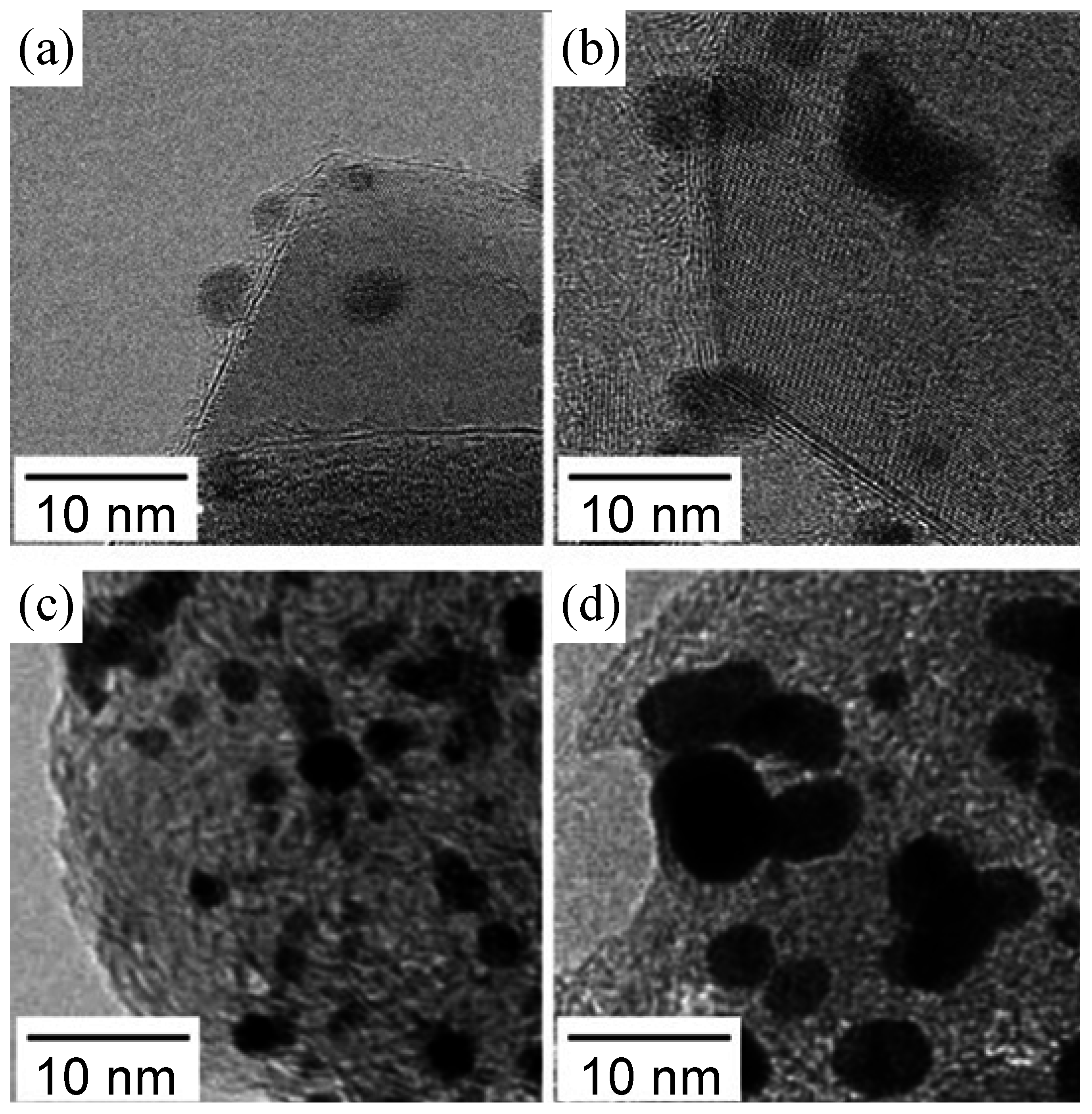
2.1. Characterization of Pt/TiC Catalysts

Figure 1 shows X-ray diffraction (XRD) patterns of various Pt/TiC catalysts. The sharp peaks at 2θ = 36° and 42° for both samples were assigned to cubic TiC (111) and TiC (200), respectively. The broad peaks at 2θ = 40° and 46° for the catalysts heat-treated at 600 °C were assigned to Pt (111) and Pt (200), respectively. The Pt crystallite size dXRD, calculated from Scherrer’s equation for the XRD peak at ca. 46°, was 3.8 nm for the Pt/TiC-600 °C. However, none of peaks assigned to Pt were observed for the as-prepared Pt/TiC catalyst, suggesting that the supported particles were not metallic platinum.
Figure 1. X-ray diffraction patterns for (a) Pt/TiC as-prepared and (b) (c) heat-treated at 600 °C (Pt/TiC-600 °C). The panel (c) is the enlarged XRD pattern from 30° to 50° for Pt/TiC-600 °C. The assignment of peaks is shown by (●) cubic TiC and (▼) Pt. The peaks in (a) from low diffraction angles to high angles correspond to the lattice distance of TiC (111), (200), (220), (311), and (222). The peaks in (b) marked with ▼ correspond to the lattice distance of Pt (111), (200), (220), and (311) from low diffraction angle to high angle, respectively.
Catalysts 05 00966 g001
The X-ray photoelectron spectra of as-prepared Pt/TiC and Pt/TiC-600 °C are shown in Figure 2. The formation of Pt(II) oxide (PtO) was confirmed for the as-prepared Pt/TiC catalyst from the Pt 4f core-level region in Figure 2a. After the heat treatment at 600 °C in N2 containing 1% H2, the peak of metallic Pt (Pt0) appeared, with significant diminishing of the PtO peak, which is consistent with the XRD results described above. In Figure 2b, we observed a broad peak assigned to Ti4+, presumably TiO2, besides the main peak assigned to Ti3+ in the TiC phase. The heat treatment at 600 °C in N2 containing 1% H2 resulted in a decrease of the Ti4+ peak with a low-energy shift. Such a shift has also been ascribed to the reduction of TiO2 [38].
Figure 2. X-ray photoelectron spectra of as-prepared Pt/TiC and Pt/TiC-600 °C in the binding energy regions of (a) Pt 4f7/2 and (b) Ti 2p3/2.
Catalysts 05 00966 g002
Figure 3 shows TEM images of as-prepared Pt/TiC and Pt/TiC-600 °C, together with the particle size distribution histograms. PtO or Pt particles were well dispersed on the TiC support for both samples. The average Pt particle size dTEM of as-prepared Pt/TiC and Pt/TiC-600 °C were 1.9 ± 0.4 nm and 3.7 ± 1.0 nm, respectively. It was seen in a typical high resolution image (Figure 3b) for the as-prepared Pt/TiC that a dome-shaped particle (presumably PtO) was covered with a thin amorphous layer. After the reduction at 600 °C (Pt/TiC-600 °C, Figure 3d), clear fringes corresponding to the (111) lattice distance of Pt (0.224 nm) were observed, without any thin amorphous layer.
Considering the XPS results shown in Figure 2, the thin amorphous layer observed in Figure 3d can be assigned with certainty to TiO2, which was reduced at 600 °C in 1% H2. The dTEM of Pt on Pt/TiC-600 °C accords well with the crystallite sizes dXRD, i.e., each Pt particle observed by TEM was a single crystallite. The Pt loading amount on the Pt/TiC-600 °C was quantified to be 10.3 wt % (see Experimental section). Thus, we clarified that Pt nanocrystals were formed on the TiC support by the reduction of TiO2-covered PtO particles, followed by agglomeration. It is also noted that most of Pt nanocrystals dispersed on the TiC support were hemispherical as seen in Figure 3d, suggesting a strong interaction between Pt and the support.
Figure 3. Transmission electron microscopic (TEM) images of as-prepared Pt/TiC (a) (b) and Pt/TiC-600 °C (c) (d), together with the Pt particle size distribution histograms.
Catalysts 05 00966 g003

2.2. Electrochemical Characterization of Pt/TiC Catalysts

Figure 4 shows the cyclic voltammograms (CVs) of the Nafion-coated Pt/TiC-600 °C and c-Pt/CB electrodes in N2-purged 0.1 M HClO4 solution measured at 25 °C. For both electrodes, the hydrogen adsorption/desorption peaks were clearly observed at potentials below 0.4 V. The oxidation of Pt commenced at approximately 0.8 V in the positive-going scan, while the reduction peak was seen at 0.75 V in the negative-going scan. The ECA values of Pt/TiC-600 °C and c-Pt/CB, which were evaluated from the hydrogen adsorption charge in Figure 4, were 75 m2 gPt−1 and 80 m2 gPt−1 [39], respectively. Assuming a spherical shape for the Pt particles with dTEM, the specific surface area was calculated to be 76 m2 gPt−1 for Pt/TiC-600 °C and 127 m2 gPt−1 for c-Pt/CB. This suggests that nearly all Pt particles for the Pt/TiC-600 °C catalyst can easily contact the electrolyte solution, whereas an appreciable fraction of the Pt particles in the c-Pt/CB catalyst cannot contact the electrolyte solution. It has been reported that nearly half of the Pt particles for c-Pt/CB were located in the interiors of carbon black particles [40].
Figure 4. Cyclic voltammograms for Pt/TiC-600 °C and c-Pt/CB in N2-saturated 0.1 M HClO4 at a sweep rate of 0.1 V s−1.
Catalysts 05 00966 g004
The ORR was examined by the RDE technique in O2-saturated 0.1 M HClO4 solution at 25 °C. Hydrodynamic voltammograms for the ORR at Pt/TiC-600 °C and c-Pt/CB electrodes are shown in Figure 5. Both Pt/TiC-600 °C and c-Pt/CB electrodes exhibited nearly identical onset potential (0.98 V) for the ORR. The ORR current reached a diffusion limit at about 0.4 V. Then, the limiting current-corrected current, ILCC = I × IL/(ILI), was calculated at 1500 rpm. According to the Koutecky-Levich equation, ILCC is equivalent to the kinetically-controlled current Ik.
Figure 5. Hydrodynamic voltammograms for the ORR at Nafion-coated Pt/TiC-600 °C and c-Pt/CB in O2-saturated 0.1 M HClO4 solution at 25 °C. Rotating rate was 1500 rpm, and the potential sweep rate was 5 mV s−1.
Catalysts 05 00966 g005
Figure 6 shows Tafel plots (E vs. log |ILCC|) for the ORR at Pt/TiC-600 °C and c-Pt/CB. The Pt/TiC-600 °C showed two Tafel slope regions, similar to the case of c-Pt/CB: ca. −60 mV decade−1 in the high potential region E > 0.9 V, and ca. −120 mV decade−1 in the low potential region E 0.85 V, being in agreement with those reported for bulk-Pt or Pt/CB [41]. Therefore, the rate determining step for the ORR at Pt/TiC-600 °C is identical with that at Pt/CB or bulk-Pt.
Figure 6. Tafel plots for the ORR at Pt/TiC-600 °C and c-Pt/CB in O2-saturated 0.1 M HClO4 solution at 25 °C with the rotating rate of 1500 rpm and the potential sweep rate of 5 mV s−1.
Catalysts 05 00966 g006
The kinetically-controlled currents Ik at given potentials E were determined based on the Koutecky-Levich equation,
1/I = 1/Ik + 1/(0.62 n F S D2/3 CO ν−1/6 ω1/2)
where n is the number of electrons transferred, F is the Faraday constant, S is the effective projected area of the Pt catalyst, D is the diffusion coefficient of O2, CO is the oxygen concentration, ν is the viscosity of the electrolyte and ω is the angular velocity. An example of the Koutecky-Levich plot for the ORR on the Nafion-coated Pt/TiC-600 °C is shown in Figure 7. Linear relationships with a constant slope are seen at all of the potentials, 0.85, 0.80 and 0.76 V. By extrapolating ω−1/2 to 0 (infinite mass transport rate), the value of the kinetically controlled current Ik was calculated. The kinetically-controlled specific activity (jk) and mass activity (MA) were calculated based on the ECA value and the amount of Pt initially loaded on the working electrode, respectively. The value of jk of Pt/TiC-600 °C at 0.85 V was 0.70 mA cm−2, which was approximately 1.4 times higher than that of c-Pt/CB. Similar enhancement factors of the jk were also reported for Pt/Nb–SnO2−δ and Pt/Ta–SnO2−δ [29,30]. The value of MA of Pt/TiC-600 °C at 0.85 V (507 A g−1) was, however, comparable to that of c-Pt/CB (527 A g−1), since the ECA of Pt/TiC-600 °C was smaller than that of c-Pt/CB.
So far, the MA or jk at 0.90 V has been evaluated in both RDE cells using 0.1 M HClO4 electrolyte solution and conventional membrane-electrode assemblies (MEAs), e.g., with 0.40 mgPt cm−2 loading operated with air of 150 kPaabsolute humidified at 100% RH [42]. In contrast, the current density at 0.90 V is not completely kinetically-controlled in recent MEAs with less Pt loading of 0.04 mgPt cm−2 and a thin electrolyte membrane operated under ambient pressure at low humidity (30% RH) [43,44]. We have therefore judged that the MA measured at 0.85 V is more appropriate, considering the actual operating conditions of PEFCs [44]. However, in order to compare the ORR activity of our Pt/TiC-600 °C with values in the literature, we have also evaluated the jk at 0.90 V and 25 °C with the potential sweep rate of 5 mV s−1 to be 0.17 mA cm−2. The value of jk is consistent with those of Pt/CB catalysts at 0.90 V and 60 °C (with the same sweep rate) [42]. Although the jk values summarized in the literature were evaluated at higher temperature than the present work, such an accordance is certainly due to a small effect of temperature on jk for the ORR since an increase in the ORR activity with increasing temperature is almost cancelled by the decrease in O2 solubility [45]. Recently, Ignaszak et al. prepared a Pt/TiC catalyst with similar Pt size dTEM = 3.1 nm by a microwave-assisted polyol process [46]. They reported a jk value at 0.90 V of 0.024 mA cm−2, which is only 1/7 of our value. It is also noted that the value of ECA reported was 40 m2 gPt−1, which is approximately 1/2 that of our catalyst (76 m2 gPt−1). The most important difference, we consider, is that Ignaszak et al. did not carry out any heat treatment after dispersing the Pt on TiC. As described above, the heat treatment in H2-containing atmosphere was found to be essential to remove the thin amorphous TiO2 layer from the Pt surface. Because the current density during the ORR is higher than that of the CV (hydrogen adsorption/desorption), it is reasonable that the effect of the oxide layer on Pt and/or the Pt–TiC interface would be more pronounced for the jk values for the ORR than it would be for the ECA values.
Figure 7. Koutecky-Levich plots obtained from hydrodynamic voltammograms for the ORR (shown in the inset) at (▲) 0.85 V, (●) 0.80 V and (♦) 0.76 V vs. RHE at Nafion-coated Pt/TiC-600 °C electrode in O2-saturated 0.1 M HClO4 solution at 25 °C.
Catalysts 05 00966 g007

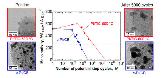
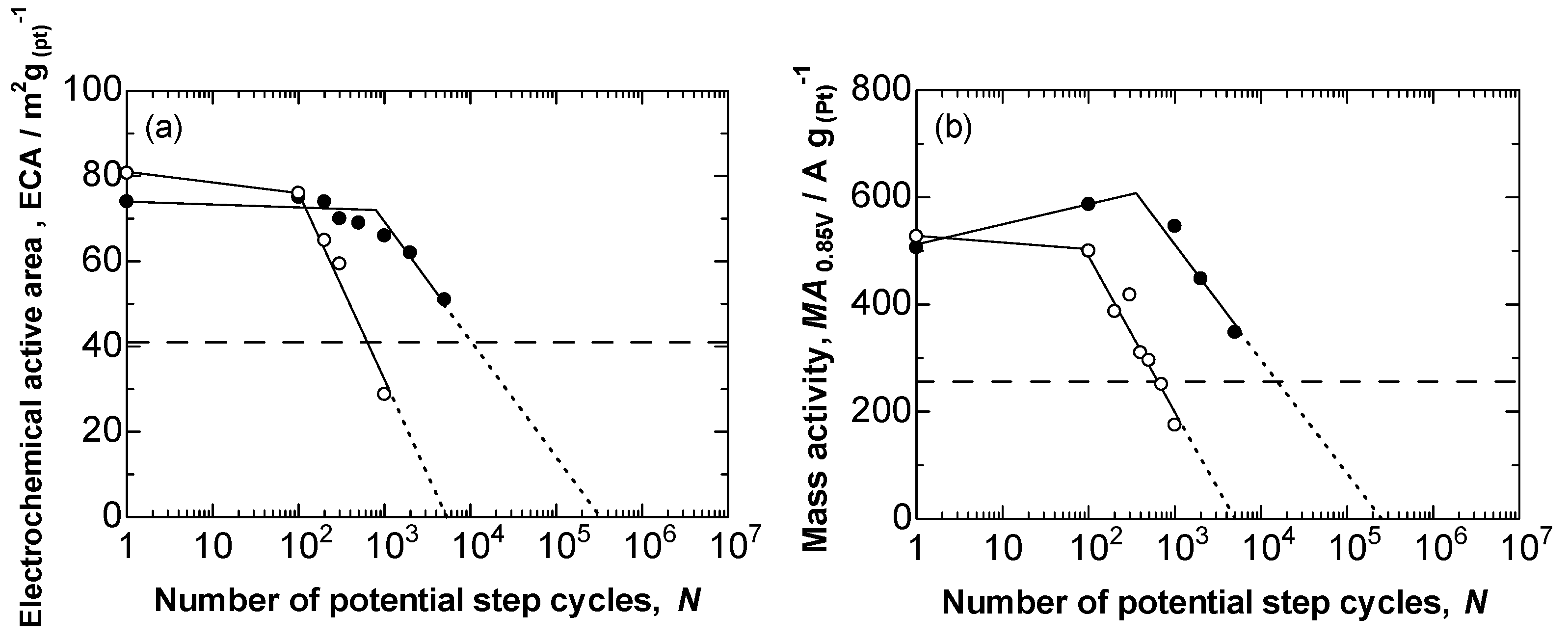
2.3. Durability of Pt/TiC-600 °C in the Potential Step Cycle Test

Then, we have examined the durability of the Pt/TiC catalyst at high potentials. Figure 8a shows the changes in the ECA values of the Nafion-coated Pt/TiC-600 °C and c-Pt/CB electrodes during the potential step cycle test, simulating the start-stop cycles of the FCV. The ECA values of c-Pt/CB decreased quickly after 100 cycles, whereas the ECA values of Pt/TiC-600 °C decreased slowly. As a measure of the durability, we defined N1/2,ECA, i.e., the value of N at which ECA had decreased to 1/2 of the initial value of c-Pt/CB. It is clear that Pt/TiC-600 °C showed a much lower rate of ECA decrease; the N1/2,ECA value for Pt/TiC-600 °C was 12 times larger than that for c-Pt/CB. Figure 8b shows changes in the MA at 0.85 V (MA0.85V) for the ORR on the Nafion-coated Pt/TiC-600 °C and c-Pt/CB electrodes as a function of log N. The Pt/TiC-600 °C exhibited a much lower rate of MA decrease than c-Pt/CB. The value of N at which MA had decreased to 1/2 of the initial value, N1/2,MA, for Pt/TiC-600 °C was 11 times larger than that for c-Pt/CB. These results suggest that the decrease in the MA of Pt/TiC-600 °C can be ascribed mainly to the decrease in ECA.
Figure 8. (a) Plots of ECA at Nafion-coated (●) Pt/TiC-600 °C and (○) c-Pt/CB electrodes as a function of log N. (b) Plots of MA0.85V at Nafion-coated (●) Pt/TiC-600 °C and (○) c-Pt/CB electrodes at 0.85 V as a function of log N. Each dashed line indicates 1/2 of the initial value of (a) ECA and (b) MA0.85V for c-Pt/CB.
Catalysts 05 00966 g008
Figure 9. TEM images of Pt/TiC-600 °C (a) (b) and c-Pt/CB (c) (d) before (a) (c) and after (b) (d) the durability test (N = 5000).
Catalysts 05 00966 g009
Figure 9 shows the TEM images of Pt/TiC-600 °C and c-Pt/CB before and after the durability test (N = 5000). As is well known, the CB support of c-Pt/CB corrodes severely at high potentials [17,39]. Many Pt particles were found to be detached from the CB support, in addition to the agglomeration of Pt particles. It was found that Pt/TiC-600 °C exhibited high durability at high potentials, and Pt particles were not detached from the TiC support. The slow decrease of the ECA and MA values of Pt/TiC-600 °C can certainly be ascribed to an agglomeration of Pt particles. In contrast, Ignaszak et al. claimed [46] that their Pt/TiC lost 78% of its original ORR activity after only 500 potential cycles between 0.05 V and 1.2 V at 20 mV s−1. Although the test protocol (upper limit and lower limit potential, potential sweep vs. potential step) was different, our Pt/TiC-600 °C catalyst exhibited superior durability, even with a higher potential being used, i.e., 1.3 V. Thus, we have confirmed that the removal of the TiO2 layer, as we performed for Pt/TiC-600 °C, was very important to obtain both high ORR activity and high durability at high potentials The next target will be to examine this catalyst in the MEA.

3. Experimental Section

3.1. Preparation of Pt/TiC Catalyst

TiC nanoparticles (average diameter = ca. 40 nm, prepared by a radio-frequency plasma method) were supplied by Nisshin Engineering Co. (Tokyo, Japan) The surface area of the TiC nanoparticles was measured to be 77 m2 gPt−1 by the Brunauer, Emmett and Teller (BET) adsorption method (BELSORP-max, BEL Japan Inc., Osaka, Japan). Platinum nanoparticles were dispersed on the TiC support by the colloidal method [26,36,37]. A calculated amount of hexachloroplatinic acid was dissolved in sodium hydrogen sulfite solution under stirring. In order to prepare a Pt (or PtOx) colloid, hydrogen peroxide was added to the solution at a rate of 2 mL min−1, and the pH value was held at 5.0 by adding 5 wt. % sodium hydroxide solution. A dispersion of TiC powder, pure water (Milli-Q water, 18.2 MΩ cm, Millipore Japan Co., Ltd., Tokyo, Japan) and catalase (to decompose excess H2O2) were added into the Pt colloid solution at room temperature, followed by stirring for 6 h. The powder obtained was filtered and washed thoroughly with pure water. The powder (PtOx/TiC) was then heat-treated at 600 °C in 1% H2-containing N2 atmosphere for 2 h and quenched to room temperature. The amount of Pt loaded on the TiC support was measured by an inductively coupled plasma-mass spectrometric analyzer (ICP-MS, 7500CX, Agilent Technologies Inc., Tokyo, Japan). The Pt loading amount on the Pt/TiC-600 °C was found to be 10.3 wt %. Considering the density of TiC (4.91 g cm−3, based on JCPDS#321383 data) and carbon black (ca. 2 g cm−3), we can estimate that the thickness of the catalyst layer with 10.3 wt %-Pt/TiC is comparable to that with ca. 25 wt %-Pt/CB under the given Pt amount and the porosity.

3.2. Characterization of Pt/TiC

The crystalline phase of the Pt/TiC catalyst was characterized using X-ray diffraction (XRD, Ultima 4, Rigaku Co., Tokyo, Japan) with monochromated CuKα radiation (0.15406 nm, 40 kV, 40 mA). The morphology of the catalyst was observed by transmission electron microscopy (TEM, H-9500, Hitachi High-Technologies Co., Tokyo, Japan) and scanning transmission electron microscopy (STEM, HD-2700, Hitachi High-Technologies Co.). The Pt (or PtOx)/TiC catalyst was also analyzed by X-ray photoelectron spectroscopy (XPS, ESCA5800, ULVAC-PHI Inc., Chigasaki, Japan).

3.3. Electrochemical Measurements

The ORR activities of the Pt/TiC and a c-Pt/CB (TEC10E50E, 45.6 wt %-Pt supported on high-surface-area carbon black, Tanaka Kikinzoku Kogyo K.K., Tokyo, Japan) catalysts were examined by the rotating disk electrode (RDE) technique. The working electrode consisted of a thin layer of these catalysts uniformly dispersed on a glassy carbon disk substrate (diameter = 5 mm, geometric area = 0.196 cm2) at a constant loading of 5.50 μgPt cm−2, which corresponds to an approximately 2.5-monolayer height of TiC support particles. A thin film of Nafion was coated on the catalyst layer with an average thickness of 0.05 μm [39]. The use of such a thin catalyst layer with a thin Nafion film enables us to evaluate a “real” kinetically-controlled activity of the catalyst for the ORR [47].
A platinum wire and a reversible hydrogen electrode (RHE) were used as the counter and the reference electrodes, respectively. The electrolyte solution of 0.1 M HClO4 was prepared from reagent-grade chemicals (Kanto Chemical Co., Tokyo, Japan) and Milli-Q water. All of the electrode potentials were controlled by a potentiostat (HZ5000, Hokuto Denko Co., Tokyo, Japan). The electrolyte solution was saturated with N2 or O2 gas bubbling for at least 1 h prior to the electrochemical measurements.
The durability testing of the catalysts was performed according to a standard potential step protocol recommended by the Fuel Cell Commercialization Conference of Japan (FCCJ) in 0.1 M HClO4 solution purged with N2 at 25 °C. The potential was stepped between 0.9 V and 1.3 V, with a holding period of 30 s at each potential (1 min per cycle) [48]. After a given number of potential step cycles, changes in the ECA values and ORR activities were examined.

4. Conclusions

We have succeeded in preparing Pt nanoparticles uniformly dispersed on a TiC support (Pt/TiC) by the colloidal method, followed by heat treatment in a hydrogen-containing atmosphere. Such a heat treatment was found to be important in removing a thin amorphous TiO2 layer from the Pt surface, resulting in hemispherical Pt nanocrystals with clear lattice fringes. The heat-treated Pt/TiC at 600 °C (Pt/TiC-600 °C) exhibited high MA for the ORR in O2-saturated 0.1 M HClO4 solution at 25 °C, comparable to that of c-Pt/CB. It was also found that Pt/TiC-600 °C exhibited much higher durability than that of c-Pt/CB in a standard a potential step protocol (E = 0.9 V ↔ 1.3 V). By TEM observation, we have clearly demonstrated that the major reason for such a high durability of Pt/TiC-600 °C was suppression of the detachment of Pt particles from the support, unlike c-Pt/CB. Hence, based on our systematic work using various ceramic supports (TiN [26], doped SnO2 [27,28,29,30], and TiC in the present work), the essential factors for the highly active and highly durable cathode catalysts are the use of a chemically and electro chemically stable support with high electrical conductivity, uniform dispersion of Pt nanocrystals on the support, and the removal of an oxide layer, if any, on the Pt surface and/or Pt-ceramic support interface.

Acknowledgments

This work was supported by funds for the Research on Nanotechnology for High Performance Fuel Cells (“HiPer-FC”) Project of the New Energy and Industrial Technology Development Organization (NEDO) of Japan.

Author Contributions

This work was coordinated by Hiroyuki Uchida and Masahiro Watanabe. Morio Chiwata carried out the preparation and characterization (XRD, TEM, and ICP-MS) of catalysts, and performed the electrochemical measurements (CVs and RDE). Katsuyoshi Kakinuma contributed to the preparation and characterization (high-resolution TEM and RDE) of catalysts. Mitsuru Wakisaka performed XPS analysis. Makoto Uchida and Shigehito Deki contributed to the durability tests and all of the characterization. All the authors contributed equally to the data interpretation and discussion. Morio Chiwata prepared the manuscript, and Hiroyuki Uchida revised the final version of paper.

Conflicts of Interest

The authors declare no conflict of interest.

References

  1. Wilson, M.S.; Garzon, F.H.; Sickafus, K.E.; Gottesfeld, S. Surface Area Loss of Supported Platinum in Polymer Electrolyte Fuel Cells. J. Electrochem. Soc. 1993, 140, 2872–2877. [Google Scholar] [CrossRef]
  2. Willsaw, J.; Heitbaum, J. The Influence of Pt-activation on the Corrosion of Carbon in Gas Diffusion Electrodes—A DEMS Study. J. Electroanal. Chem. 1984, 161, 93–101. [Google Scholar] [CrossRef]
  3. Yu, X.; Ye, S. Recent Advances in Activity and Durability Enhancement of Pt/C Catalytic Cathode in PEMFC: Part II: Degradation Mechanism and Durability Enhancement of Carbon Supported Platinum Catalyst. J. Power Sources 2007, 172, 145–154. [Google Scholar] [CrossRef]
  4. Tang, H.; Qi, Z.G.; Ramani, M.; Elter, J.F. PEM Fuel Cell Cathode Carbon Corrosion Due to the Formation of Air/Fuel Boundary at the Anode. J. Power Sources 2006, 158, 1306–1312. [Google Scholar] [CrossRef]
  5. Meyers, J.P.; Darling, R.M. Model of Carbon Corrosion in PEM Fuel Cells. J. Electrochem. Soc. 2006, 153, A1432–A1442. [Google Scholar] [CrossRef]
  6. Reiser, C.A.; Bregoli, L.; Patterson, T.W.; Yi, J.S.; Yang, D.; Perry, M.L.; Jarvi, T.D. A Reverse-Current Decay Mechanism for Fuel Cells. Electrochem. Solid-State Lett. 2005, 8, A273–A276. [Google Scholar] [CrossRef]
  7. Borup, R.L.; Davey, J.R.; Garzon, H.F.; Wood, D.J.; Inbody, M.A. PEM Fuel Cell Electrocatalyst Durability Measurements. J. Power Sources 2006, 163, 76–81. [Google Scholar] [CrossRef]
  8. Roen, L.M.; Paik, C.H.; Jarvi, T.D. Electrocatalytic Corrosion of Carbon Support in PEMFC Cathodes. Electrochem. Solid-State Lett. 2004, 7, A19–A22. [Google Scholar] [CrossRef]
  9. Passalacqua, E.; Antonucci, P.L.; Vivadi, M.; Patti, A.; Antonucci, V.; Giordano, N.; Kinoshita, K. The Influence of Pt on the Electrooxidation Behaviour of Carbon in Phosphoric Acid. Electrochim. Acta 1992, 37, 2725–2730. [Google Scholar] [CrossRef]
  10. Ferreira, P.J.; Lao, G.J.; Shao-Horn, Y.; Morgan, D.; Makharia, R.; Kocha, S.; Gasteiger, H.A. Instability of Pt/C Electrocatalysts in Proton Exchange Membrane Fuel Cells A Mechanistic Investigation. J. Electrochem. Soc. 2005, 152, A2256–A2271. [Google Scholar] [CrossRef]
  11. Darling, R.M.; Meyers, J.P. Kinetic Model of Platinum Dissolution in PEMFCs. J. Electrochem. Soc. 2003, 150, A1523–A1527. [Google Scholar] [CrossRef]
  12. Xie, J.; Wood, D.L.; Wayne, D.M.; Zawodinski, T.A.; Atanassov, P.; Borup, R.L. Durability of PEFCs at High Humidity Conditions. J. Electrochem. Soc. 2005, 152, A104–A113. [Google Scholar] [CrossRef]
  13. Xie, J.; Wood, D.L.; More, K.L.; Atanassov, P.; Borup, R.L. Microstructural Changes of Membrane Electrode Assemblies during PEFC Durability Testing at High Humidity Conditions. J. Electrochem. Soc. 2005, 152, A1011–A1020. [Google Scholar] [CrossRef]
  14. Stevens, D.A.; Hicks, M.T.; Haugen, G.M.; Dahn, J.R. Ex situ and in situ Stability Studies of PEMFC Catalysts Effect of Carbon Type and Humidification on Degradation of the Carbon. J. Electrochem. Soc. 2005, 152, A2309–A2315. [Google Scholar] [CrossRef]
  15. Patterson, T.W.; Darling, R.M. Damage to the Cathode Catalyst of a PEM Fuel Cell Caused by Localized Fuel Starvation. Electrochem. Solid-State Lett. 2006, 9, A183–A185. [Google Scholar] [CrossRef]
  16. Yoda, T.; Uchida, H.; Watanabe, M. Effects of Operating Potential and Temperature on Degradation of Electrocatalyst Layer for PEFCs. Electrochim. Acta 2007, 52, 5997–6006. [Google Scholar] [CrossRef]
  17. Hara, M.; Lee, M.; Liu, C.-Y.; Chen, B.-H.; Yamashita, Y.; Uchida, M.; Uchida, H.; Watanabe, M. Electrochemical and Raman Spectroscopic Evaluation of Pt/Graphitized Carbon Black Catalyst Durability for the Start/Stop Operating Condition of Polymer Electrolyte Fuel Cells. Electrochim. Acta 2012, 70, 171–181. [Google Scholar] [CrossRef]
  18. Masao, A.; Noda, S.; Takasaki, F.; Ito, K.; Sasaki, K. Carbon-Free Pt Electrocatalysts Supported on SnO2 for Polymer Electrolyte Fuel Cells. Electrochem. Solid-State Lett. 2009, 12, B119–B122. [Google Scholar] [CrossRef]
  19. Takasaki, F.; Matsuie, S.; Takabatake, Y.; Noda, Z.; Hayashi, A.; Shiratori, Y.; Ito, K.; Sasaki, K. Carbon-Free Pt Electrocatalysts Supported on SnO2 for Polymer Electrolyte Fuel Cells: Electrocatalytic Activity and Durability. J. Electrochem. Soc. 2011, 158, B1270–B1275. [Google Scholar] [CrossRef]
  20. Mentus, S.V. Oxygen Reduction on Anodically Formed Titanium Dioxide. Electrochim. Acta 2007, 50, 27–32. [Google Scholar] [CrossRef]
  21. Ioroi, T.; Akita, T.; Yamazaki, S.; Siroma, Z.; Fujiwara, N.; Yasuda, K. Corrosion-Resistant PEMFC Cathode Catalysts Based on a Magnéli-Phase Titanium Oxide Support Synthesized by Pulsed UV Laser Irradiation. J. Electrochem. Soc. 2011, 158, C329–C334. [Google Scholar] [CrossRef]
  22. Huang, S.Y.; Ganesan, P.; Park, S.; Popov, B.N. Development of a Titanium Dioxide-Supported Platinum Catalyst with Ultrahigh Stability for Polymer Electrolyte Membrane Fuel Cell Applications. J. Am. Chem. Soc. 2009, 131, 13898–13899. [Google Scholar] [CrossRef] [PubMed]
  23. Huang, S.Y.; Ganesan, P.; Park, S.; Popov, B.N. Titania Supported Platinum Catalyst with High Electrocatalytic Activity and Stability for Polymer Electrolyte Membrane Fuel Cell. Appl. Catal. B 2011, 102, 71–77. [Google Scholar] [CrossRef]
  24. Ioroi, T.; Senoh, H.; Yamazaki, S.; Siroma, Z.; Fujiwara, N.; Yasuda, K. Stability of Corrosion-Resistant Magnéli-Phase Ti4O7-Supported PEMFC Catalysts at High Potentials. J. Electrochem. Soc. 2008, 155, B321–B326. [Google Scholar] [CrossRef]
  25. Ioroi, T.; Siroma, Z.; Fujiwara, N.; Yamazaki, S.; Yasuda, K. Sub-Stoichiometric Titanium Oxide-Supported Platinum Electrocatalyst for Polymer Electrolyte Fuel Cells. Electrochem. Commun. 2005, 7, 183–188. [Google Scholar] [CrossRef]
  26. Kakinuma, K.; Wakasugi, Y.; Uchida, M.; Kamino, T.; Uchida, H.; Deki, S.; Watanabe, M. Preparation of Titanium Nitride-Supported Platinum Catalysts with Well Controlled Morphology and Their Properties Televant to Polymer Electrolyte Fuel Cells. Electrochim. Acta 2012, 77, 279–284. [Google Scholar] [CrossRef]
  27. Kakinuma, K.; Uchida, M.; Kamino, T.; Uchida, H.; Watanabe, M. Synthesis and Electrochemical Characterization of Pt Catalyst Supported on Sn0.96Sb0.04O2−δ with a Network Structure. Electrochim. Acta 2011, 56, 2881–2887. [Google Scholar] [CrossRef]
  28. Kakinuma, K.; Chino, Y.; Senoo, Y.; Uchida, M.; Kamino, T.; Uchida, H.; Deki, S.; Watanabe, M. Characterization of Pt catalysts on Nb-Doped and Sb-Doped SnO2−δ Support Materials with Aggregated Structure by Rotating Disk Electrode and Fuel Cell Measurements. Electrochim. Acta 2013, 110, 316–324. [Google Scholar] [CrossRef]
  29. Senoo, Y.; Kakinuma, K.; Uchida, M.; Uchida, H.; Deki, S.; Watanabe, M. Improvements in Electrical and Electrochemical Properties of Nb-Doped SnO2 Supports for Fuel Cell Cathodes Due to Aggregation and Pt Loading. RSC Adv. 2014, 4, 32180–32188. [Google Scholar] [CrossRef]
  30. Senoo, Y.; Taniguchi, K.; Kakinuma, K.; Uchida, M.; Uchida, H.; Deki, S.; Watanabe, M. Cathodic Performance and High Potential Durability of Ta–SnO2−δ-Supported Pt Catalysts for PEFC Cathodes. Electrochem. Commun. 2015, 51, 37–40. [Google Scholar] [CrossRef]
  31. Oyama, S.T. The Chemistry of Transition Metal Carbides and Nitrides; Blackie Academic and Professional: London, UK, 1996; Chapter 1; pp. 9–14. [Google Scholar]
  32. Nakao, S.; Yamada, N.; Hitosugi, T.; Hirose, Y.; Shimada, T.; Hasegawa, T. High Mobility Exceeding 80 cm2 V−1 s−1 in Polycrystalline Ta-Doped SnO2 Thin Films on Glass Using Anatase TiO2 Seed Layers. Appl. Phys. Express 2010, 3, 031102. [Google Scholar] [CrossRef]
  33. La Conti, A.B.; Griffith, A.E.; Cropley, C.C.; Kosek, J.A. Titanium Carbide Bipolar Plate for Electrochemical Devices. U.S. Patent 6,083,641, 4 July 2000. [Google Scholar]
  34. Jalan, V.; Frost, D.G. Fuel Cell Electrocatalyst Support Comprising an Ultra-Fine Chainy-Structured Titanium Carbide. U.S. Patent 4,795,684, 3 January 1989. [Google Scholar]
  35. Ma, L.; Sui, S.; Zhai, Y. Preparation and Characterization of Ir/TiC Catalyst for Oxygen Evolution. J. Power Sources 2008, 177, 470–477. [Google Scholar] [CrossRef]
  36. Watanabe, M.; Uchida, M.; Motoo, S. Application of the Gas Diffusion Electrode to a Backward Feed and Exhaust (BFE) Type Methanol Anode. J. Electroanal. Chem. 1986, 199, 311–322. [Google Scholar] [CrossRef]
  37. Watanabe, M.; Uchida, M.; Motoo, S. Preparation of Highly Dispersed Pt + Ru Clusters and the Activity for the Electro-Oxidation of Methanol. J. Electroanal. Chem. 1987, 229, 395–406. [Google Scholar] [CrossRef]
  38. Brambilla, A.; Calloni, A.; Berti, G.; Bussetti, G.; Duò, L.; Ciccacci, F. Growth and Interface Reactivity of Titanium Oxide Thin Films on Fe(001). J. Phys. Chem. C 2013, 117, 9229–9236. [Google Scholar] [CrossRef]
  39. Yano, H.; Akiyama, T.; Bele, P.; Uchida, H.; Watanabe, M. Durability of Pt/Graphitized Carbon Catalysts for the Oxygen Reduction Reaction Prepared by the Nanocapsule Method. Phys. Chem. Chem. Phys. 2010, 12, 3806–3814. [Google Scholar] [CrossRef] [PubMed]
  40. Uchida, M.; Park, Y.-C.; Kakinuma, K.; Yano, H.; Tryk, A.D.; Kamino, T.; Uchida, H.; Watanabe, M. Effect of the State of Distribution of Supported Pt Nanoparticles on Effective Pt Utilization in Polymer Electrolyte Fuel Cells. Phys. Chem. Chem. Phys. 2013, 5, 11236–11247. [Google Scholar] [CrossRef] [PubMed]
  41. Markovic, N.; Adzic, R.; Cahan, B.; Yeager, E. Structural Effects in Electrocatalysis: Oxygen Reduction on Platinum Low Index Single-Crystal Surfaces in Perchloric Acid Solutions. J. Electroanal. Chem. 1994, 377, 249–259. [Google Scholar] [CrossRef]
  42. Gasteiger, H.A.; Kocha, S.S.; Sompalli, B.; Wagner, F.T. Activity Benchmarks and Requirements for Pt, Pt-alloy, and Non-Pt Oxygen Reduction Catalysts for PEMFCs. Appl. Catal. B Environ. 2005, 56, 9–35. [Google Scholar] [CrossRef]
  43. Lee, M.; Uchida, M.; Tryk, D.A.; Uchida, H.; Watanabe, M. The Effectiveness of Platinum/Carbon Electrocatalysts: Dependence on Catalyst Layer Thickness and Pt Alloy Catalytic Effects. Electrochim. Acta 2011, 56, 4783–4790. [Google Scholar] [CrossRef]
  44. Okaya, K.; Yano, H.; Kakinuma, K.; Watanabe, M.; Uchida, H. Temperature Dependence of Oxygen Reduction Reaction Activity at Stabilized Pt Skin-PtCo Alloy/Graphitized Carbon Black Catalysts Prepared by a Modified Nanocapsule Method. ACS Appl. Mater. Interfaces 2012, 4, 6982–6991. [Google Scholar] [CrossRef] [PubMed]
  45. Paulus, U.A.; Schmidt, T.J.; Gasteiger, H.A.; Behm, R.J. Oxygen Reduction on a High-surface Area Pt/Vulcan Carbon Catalyst: A Thin-film Rotating Ring-Disk Electrode Study. J. Electroanal. Chem. 2001, 495, 134–145. [Google Scholar] [CrossRef]
  46. Ignaszak, A.; Songa, C.; Zhu, W.; Zhang, J.; Bauer, A.; Baker, R.; Neburchilov, V.; Ye, S.; Campbell, S. Titanium Carbide and Its Core-Shelled Derivative TiC@TiO2 as Catalyst Supports for Proton Exchange Membrane Fuel Cells. Electrochim. Acta 2012, 69, 397–405. [Google Scholar] [CrossRef]
  47. Higuchi, E.; Uchida, H.; Watanabe, M. Effect of Loading Level in Platinum-Dispersed Carbon Black Electrocatalysts on Oxygen Reduction Activity Evaluated by Rotating Disk Electrode. J. Electroanal. Chem. 2005, 583, 69–76. [Google Scholar] [CrossRef]
  48. Iiyama, A.; Shinohara, K.; Iguchi, S.; Daimaru, A. Handbook of Fuel Cells: Fundamentals, Technology and Applications; Vielstich, W., Lamm, A., Gasteiger, H.A., Eds.; John Wiley & Sons Ltd.: Hoboken, NJ, USA, 2009; Volume 6. [Google Scholar]

