Article

The Synergy Effect of Ni-M (M = Mo, Fe, Co, Mn or Cr) Bicomponent Catalysts on Partial Methanation Coupling with Water Gas Shift under Low H2/CO Conditions

Key Laboratory of Energy Thermal Conversion and Control of Ministry of Education, School of Energy & Environment, Southeast University, Nanjing 210096, Jiangsu, China
*
Author to whom correspondence should be addressed.
Catalysts 2017, 7(2), 51; https://doi.org/10.3390/catal7020051
Submission received: 6 January 2017 / Revised: 30 January 2017 / Accepted: 3 February 2017 / Published: 8 February 2017

Abstract

:
Ni-M (M = Mo, Fe, Co, Mn or Cr) bicomponent catalysts were prepared through the co-impregnation method for upgrading low H2/CO ratio biomass gas into urban gas through partial methanation coupling with water gas shift (WGS). The catalysts were characterized by N2 isothermal adsorption, X-ray diffraction (XRD), H2 temperature programmed reduction (H2-TPR), H2 temperature programmed desorption (H2-TPD), scanning electron microscopy (SEM) and thermogravimetry (TG). The catalytic performances demonstrated that Mn and Cr were superior to the other three elements due to the increased fraction of reducible NiO particles, promoted dispersion of Ni nanoparticles and enhanced H2 chemisorption ability. The comparative study on Mn and Cr showed that Mn was more suitable due to its smaller carbon deposition rate and wider adaptability to various H2/CO and H2O/CO conditions, indicating its better synergy effect with Ni. A nearly 100 h, the lifetime test and start/stop cycle test further implied that 15Ni-3Mn was stable for industrial application.

Graphical Abstract

1. Introduction

With the rapid development of China’s urbanization, centralized utilization of energy becomes increasingly essential. Biomass gas generated by means of gasification from organic materials, such as agricultural and forestry residues, which exist abundantly in rural places, might be one potential solution to the problem of central gas supply [1]. However, due to assorted biomass resources, as well as gasification conditions and agents [2,3,4,5,6], the H2/CO ratio of acquired biomass gas varies greatly, and particularly, low H2/CO ratio biomass gas (H2/CO < 1) cannot be applied directly by urban residents because of its dreadful toxicity and relatively low heating value. Hence, from the standpoint of safety and efficiency, a series of requisite processing technologies has to be employed in order to eliminate the above two drawbacks before it is transported through a pipeline to downstream users. As is well known, water gas shift (WGS) (Equation (1)) is highly efficient to adjust the H2/CO ratio by converting CO with H2O to CO2 and H2 [7]. In addition, methanation (Equation (2)) as one type of CO hydrogenation reaction is capable of reducing CO content and in the meantime generating CH4 that is of high heating value and innocuity. Therefore, a proper connection of these two methods could be theoretically feasible to upgrade low H2/CO ratio biomass gas into urban gas.
CO + H 2 O CO 2 + H 2   Δ H 0 = 40.6   kJ / mol
CO + 3 H 2 CH 4 + H 2 O   Δ H 0 = 206.1   kJ / mol
In reality, from a great deal of exposed literature, the collocation of a separate WGS unit and methanation unit is frequently mentioned or even has been put in practice. Earlier, this kind of combination was applied to produce synthetic natural gas (SNG) from coal [1]. Recently, it is also reported that GoBiGas (Gothenburg Biomass Gasification) biomass to the SNG process contains the same cooperation, adjusting the H2/CO ratio in a WGS reactor and yielding CH4 in another reactor [8]. Nevertheless, the entire production process from biomass gas into urban gas would be very complicated and thus difficult to manipulate if the two units were merely sequentially connected and run independently. Moreover, two individual units without integration would be considered to be not optimal economically. In other words, appropriate compression of WGS and methanation into one unit would be very advantageous on account of its convenient operability, desirable stability and low maintenance cost for the entire system. As a result, a reasonable concept is proposed to compress the two units into one unit, and a general scheme of the process chain from low H2/CO ratio biomass gas to urban gas is depicted in Figure 1. Generally, purified biomass gas passes through an integrated unit containing WGS and methanation to decrease CO content together with synthesized CH4, which is more compact than the conventional process. Subsequently, the gas upgrading unit removes part of the CO2 to increase the heating value.
For the integrated unit, the core part is the catalyst. Single methanation and WGS catalyst have been extensively investigated during the last few decades. It is reported that a variety of transition metals has exhibited their distinct methanation activity, such as Ni, Ru, Rh, Pd and Pt [9]. Meanwhile, another group of transition metals performs well in WGS, including Mo [10], Fe [11], Co [12], Mn [13,14] and Cr [15]. However, for the specific WGS plus methanation unit, it is necessary to develop a novel catalyst, which can simultaneously catalyze WGS and the methanation reaction. Scilicet, this novel catalyst is supposed to have both catalytic characteristics and inherently display a desirable synergy effect. In theory, if this desired bifunctional catalyst were developed, the catalyzed WGS could provide additional H2 for hydrogenation of CO and, further, increase the CO conversion degree. Several creative researchers provided meaningful inspirations. Ma reported that Co3O4 modified nanorod-NiO/γ-Al2O3 catalyst exhibited good activity for WGS coupling with methanation at conditions of CO/H2/H2O = 3:1:1, 593 K and atmospheric pressure [16]. Mei also found that Co/RuO2/Al2O3 (Ru/Co = 1) catalyst calcined at 350 °C owns a unique bimetallic nanoparticle structure, which led to a high CO conversion in fuel cell techniques due to the co-occurrence of methanation [17]. As a consequence, we propose to combine two different components on one support in order to catalyze WGS and methanation simultaneously. However, it should be noted that this work is different from the research above, which specifically focuses on upgrading low H2/CO ratio biomass gas into urban gas. The feed gas is an authentic, but more complex simulation of biomass gas comprised of CO, H2, N2, CO2 and H2O. Furthermore, unlike the fuel cell system, the contained CO in the biomass gas is not strictly required to be removed as thoroughly as possible. This is where the concept of partial methanation emerges. Therefore, it is essential to develop a novel, but also potentially industrial catalyst that is in good agreement with the biomass gas system. Among the above-mentioned metals, Ni is considered as the most practical choice due to its relatively high methanation activity and comparatively low cost [18]. With respect to the second component M (M = Mo, Fe, Co, Mn and Cr), it is essential to research the discrepancy when synergized with Ni and choose the best fitted one. At last, γ-Al2O3 material is adopted as the catalyst support due to its abundance and various advantages, such as high specific surface area, favorable mechanical property and satisfactory thermal stability. Particularly, from plentiful exposed literature [19,20,21], the majority of the researchers utilized powder catalysts (micrometer scale), and the employed reaction tube was comparatively small. It is well known that an inevitable drawback of massive powder catalyst is its induced problems of pressure drop. Arbeláez suggested that pelletized catalysts could solve the problem, as well as reduce the total catalyst volume and eliminate the formation of hotspots [22]. Inspired from that and considering approaching industrial application, the granular support and reaction tube with a larger size were employed in this work.
For all that is stated above, in order to investigate the feasibility of integrated methanation coupling with the WGS unit under the catalysis of Ni-M catalysts, the commercial granular-shaped γ-Al2O3 was adopted as the support and impregnated with Ni and a second metal M, resulting in the expected bicomponent catalysts. The obtained catalysts were characterized using N2 physisorption, XRD, H2-temperature programmed reduction (TPR), H2-temperature programmed desorption (TPD) and SEM. The effects of reaction temperature, H2/CO ratio and H2O/CO ratio on its activity were investigated aiming to select the best fitted catalyst, which is expected to provide a meaningful strategy for upgrading low H2/CO ratio biomass gas into urban gas and to show potential for industrial application.

2. Results and Discussion

2.1. Characterization Analysis

2.1.1. Physico-Chemical Analysis

Table 1 compiles the surface areas and pore volumes of the support and as-prepared catalysts derived from N2 adsorption analysis (Figure S2). It can be seen expressly that the surface area shrinks after the addition of Ni and/or second metal species, possibly due to the blockage of a few micropores (smaller than 2 nm) in the support framework. Even so, the catalyst samples still possess considerable surface areas (higher than 150 m2∙g−1) and pore volumes, which provide adequate conditions to facilitate the catalytic reactions. Besides, with the addition of Ni and/or the second metal, the average pore size shifts to higher values, indicating increased mesoporous size (2–50 nm) due to surface reconstruction after metal addition.

2.1.2. XRD Analysis

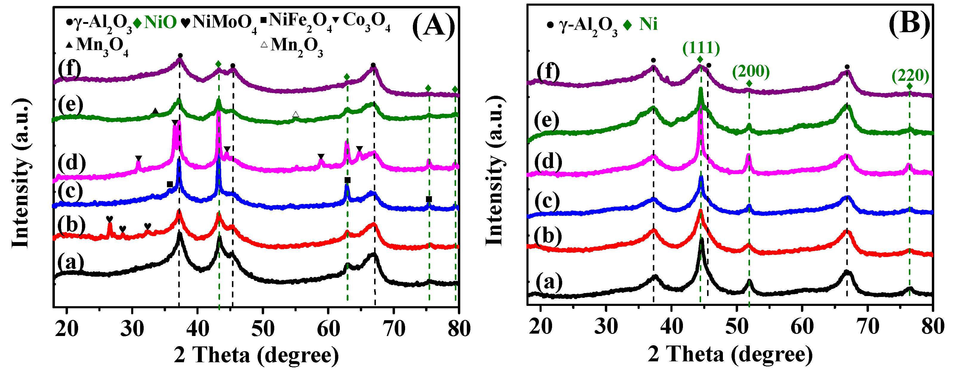
Figure 2A shows the X-ray diffraction patterns of the as-prepared 15Ni catalyst and promoted 15Ni-3M bicomponent catalysts (XRD patterns of γ-Al2O3 support are discussed additionally in Figure S3). The results of Figure 2A reveal that all of the catalysts show two major crystallite phases belonging to γ-Al2O3 and NiO, which can be indicated with diffraction peaks at 2θ = 37.4, 45.8 and 67.3° (PDF#04-0880) and diffraction peaks at 2θ = 43.2, 62.8, 75.4 and 79.4° (PDF#47-1049), respectively. However, it can be carefully noticed that the XRD patterns vary greatly with the addition of the second metal, and they can be briefly classified into three types: (1) spinel structure (b and c); (2) oxide structure (d and e); and (3) invisible structure (f). To be specific, in terms of 15Ni-3Mo and 15Ni-3Fe, the observed peaks at 2θ = 26.5, 28.5 and 33.0° are related to NiMoO4 (PDF#12-0348), and the peaks at 2θ = 35.6, 62.9 and 75.5° belong to NiFe2O4 (PDF#10-0325). In those two XRD patterns, no separate crystalline phase corresponding to FeOx and MoOx can be observed, further confirming that the iron and molybdenum in these two catalysts mainly existed in the form of spinel [23]. As for 15Ni-3Co and 15Ni-3Mn, oxide phases are clearly labeled as Co3O4 at 2θ = 31.2, 36.8, 44.8, 59.3° and Mn3O4/Mn2O3 at 2θ = 65.2° (PDF#43-1003) plus 34.0°/55.1° (PDF#04-0732/41-1442), respectively. Such an appearance of CoOx and MnOx in the XRD patterns may be due to the aggregation of oxide particles, which interacted weakly with the support. However, for 15Ni-3Cr, no signs of Cr species are displayed in its XRD pattern. Liu [24] suggested that the disappearance of the diffraction peaks of the Cr species may be due to their incorporation into the support skeleton or inferior crystallinity. High dispersion may also account for that according to some other authors [25,26].
Compared to the as-prepared catalysts, the XRD patterns of the reduced catalysts in Figure 2B seem more similar to each other. As can be seen, apart from the distinct diffraction peaks attributed to the γ-Al2O3 support, the orderly diffraction peaks of elemental Ni can be explicitly observed at 2θ = 44.5, 51.8 and 76.3°, which are correspondingly ascribed to its (111), (200) and (220) crystal plane (PDF#04-0850). In spite of the similarity, some discrepancy still can be traced concerning Ni crystal size (Table 1) after reduction. Among them, we can find that 15Ni-3Mn and 15Ni-3Cr have the smallest Ni crystal size, indicating that the addition of the appropriate amount of Mn or Cr species can greatly decrease the size of reduced Ni nanoparticles in 15Ni, whereas other species, like Fe and Co, function in an opposite way. Besides, it seems that the second metal species shows no prominent diffraction peaks in all reduced catalysts. Considering the comparatively low content of the second metal species, their interaction with coordinated sites of the γ-Al2O3 support may cause them to be below the detection limit of XRD measurements [27]. Another reason may be that the reduced second metal species is highly dispersed on the surface of catalysts by forming small particles [28].

2.1.3. H2-TPR and H2-TPD Analysis

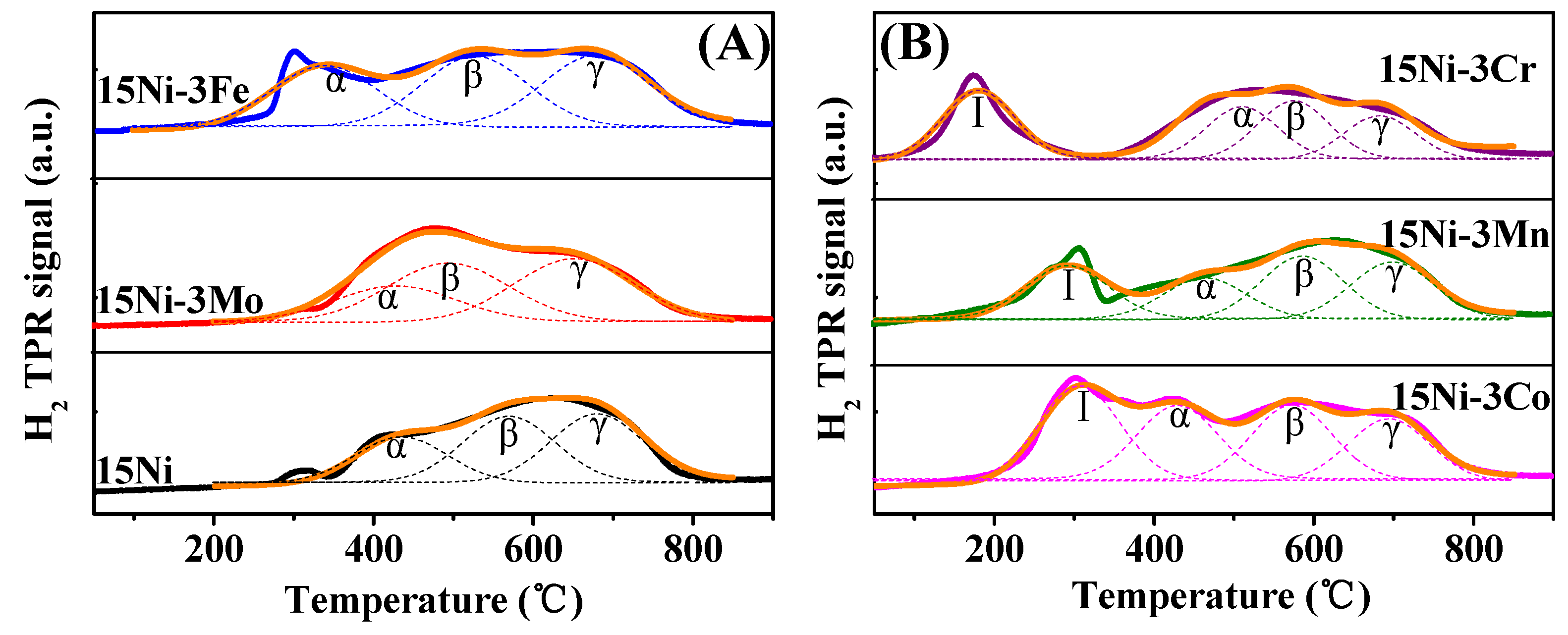
The TPR technique not only renders us the ability to differentiate the complicated metal-support interactions, but also provides us with a unique perspective, which elucidates the role of the second metal as additives in the reduction period and the influence of one or more phases on the reducibility of a specific compound in a multi-component system [28,29]. Figure 3 displays the TPR results of the as-prepared catalysts. The overlapped peaks are deconvolved into several elementary peaks using Gaussian-type functions on the basis of R2 > 0.990, which are plotted with a dashed line for differentiation. As can be seen expressly in both Figure 3A,B, the addition of the second component can greatly change the reduction characteristics of monometallic Ni-based catalyst. Judging from the peak temperatures in the TPR profiles and referring to relevant reported literature, the reducible NiO species could be sorted into three categories: (1) α-type, free nickel oxide species [30] or bulk NiO [28], which interact weakly with the support; (2) β-type, Ni-rich phases, which have medium interaction with the support; (3) γ-type, Al-rich phases, which interact strongly with the support. In Figure 3A, for 15Ni-3Mo and 15Ni-3Fe, there is no distinct reduction peak ascribed to the NiMoO4 and NiFe2O4 spinel structure. Given their relatively high reduction temperature (NiMoO4: higher than 500 °C [31]; and NiFe2O4: 402–715 °C [32]), their reduction process may be overlapped by that of NiO. However, in Figure 3B, there exists an individual peak labelled as І. According to the XRD analysis in Figure 2A, it can be deduced that the individual peak І for 15Ni-3Co is ascribed to Co3O4 reduction (Co3O4 → CoO → Co0) [33], and for 15Ni-3Mn, it corresponds to Mn2O3 reduction (Mn2O3 → Mn3O4) [30]. For 15Ni-3Cr, the individual peak І is attributed to the reduction of Cr species [24]. High dispersion and the small particle size (Table 1) may account for its low reduction temperature and invisible structure in the XRD patterns in Figure 2A.
Considering the much lower loading of second component species, we mainly focus on the reduction on NiO. For comparison, the corresponding peak temperatures and proportions of every type are shown in Table S1. The quantitative results show that with the addition of the second component, the fraction of γ-type in all reducible NiO precursors except 15Ni-3Mo decreased, suggesting a general weaker interaction between NiO and alumina support and an increased amount of easily reducible NiO. Moreover, according to the exposed literature [28,29], the reduction of α-type and β-type would favor the low temperature methanation reaction (lower than 450 °C). On the contrary, the γ-type is beneficial to high temperature methanation (600–700 °C) due to the formation of small Ni particles.
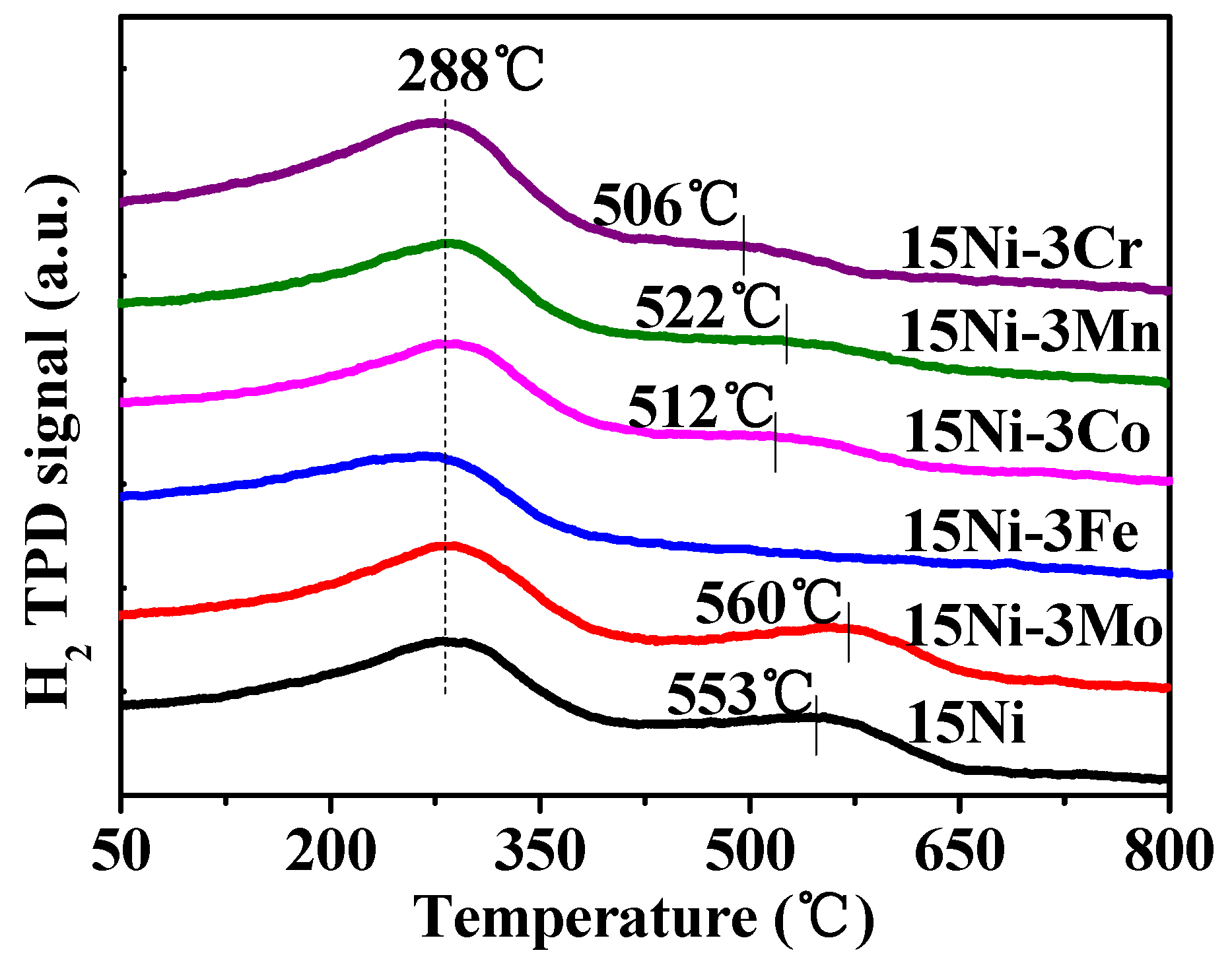
Figure 4 presents the H2-TPD curves of the reduced catalysts, and the calculated hydrogen uptakes are listed in Table 1. For 15Ni, there are two main desorption peaks, which are located at ca. 288 °C and 553 °C, respectively. However, for 15Ni-3M catalysts, the temperature of the second peak differs from that of 15Ni, implying that the Ni dispersion in the bicomponent catalysts is distinct from that in the single-component 15Ni catalyst. In accordance with others [24,30], the former peak is attributed to the chemisorbed hydrogen on the highly dispersed Ni nanoparticles with a large density of surface defects, which commonly serve as capture traps for hydrogen diffusion, leading to a capability of reducing the activation energy of hydrogen dissociation. The latter peak is supposed to be derived from the H2 adsorbed in bulk or on poorly-dispersed Ni particles. Velu [34] proposed that the former peak is ascribed to the H2 desorbed from the surface Ni particles, which indicates the exposed fraction of Ni atoms, and the latter one belongs to the H2 located in the subsurface layers and/or to spillover H2. Despite diverse theoretical explanations, they all disclosed the nature of two different forms of Ni particles. Furthermore, it is seen from Table 1 that among all of the catalysts, 15Ni-3Mn and 15Ni-3Cr have comparatively high H2 uptake of 416.8 and 405.5 μmol·g−1 and Ni dispersion of 41.0% and 42.8%, respectively, indicating that the addition of the proper second component can highly increase the dispersion of Ni nanoparticles, which are closely related with the H2 chemisorption ability in the process of catalytic reaction.

2.2. Catalytic Performances of Catalysts

2.2.1. Performance Tests

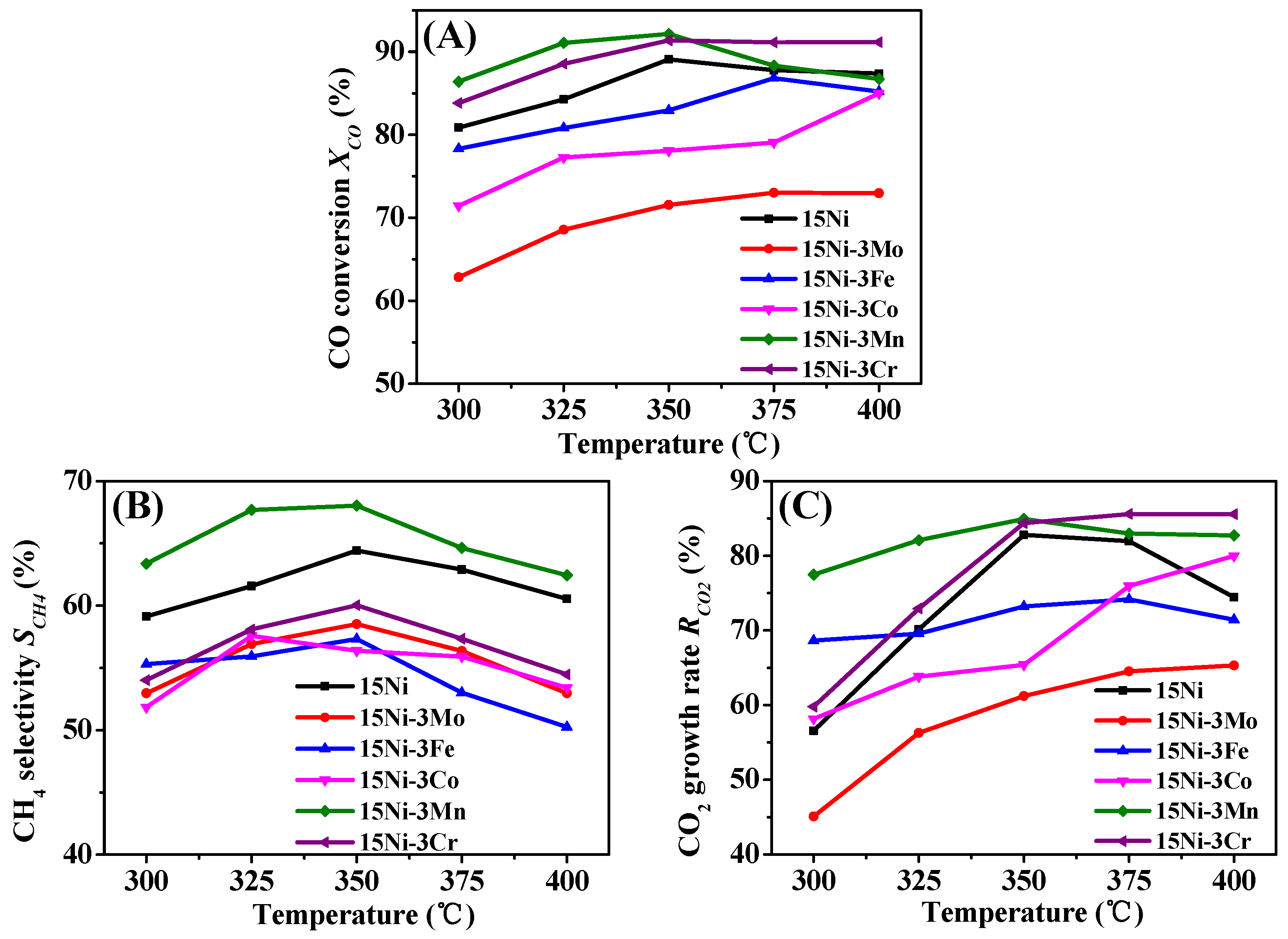
The results of partial methanation coupling with the WGS of biomass gas catalyzed by 15Ni-3M bicomponent catalysts are shown in Figure 5. It is clear that the combination of the second component M with Ni obviously influences the catalytic performances. As shown in Figure 5A, for all of the catalysts, the CO conversion increases gradually with increasing reaction temperature. However, as the reaction temperature is over 350 °C, the CO conversion starts to decrease or level off due to thermodynamic limitations, except for 15Ni-3Co, which maintains its upward momentum with temperature. This special phenomenon could be due to the prevailing performance of WGS over methanation, which is verified by the ascending CO2 growth rate in Figure 5C and descending CH4 selectivity in Figure 5B from 375–400 °C. Generally speaking, in contrast with monometallic Ni-based catalyst, 15Ni-3Mn and 15Ni-3Cr possess higher CO conversion, while the other three bicomponent catalysts, including 15Ni-3Mo, 15Ni-3Fe and 15Ni-3Co, present lower CO conversion activities, which correspond well to the TOFCO value in Table 1.
Figure 5B,C exhibits the CH4 selectivity and CO2 growth rate as a function of temperature, respectively. From Figure 5B, it can be seen that the CH4 selectivity of 15Ni-3Mn within the measured temperature range is the highest (68.03% on the top) compared to other catalysts. The trend for all of the catalysts remains accordant. The CH4 selectivity increases gradually with temperature and passes through a maximum at 350 °C, and beyond this temperature spot, a decrease in methanation catalytic activity is observed. This trending pattern meaningfully suggests us to take 350 °C as the optimum operation temperature. Different from Figure 5B,C, a less universal trending pattern of CO2 growth rate with temperature is displayed. This behavior may be caused by the addition of the second component, which greatly influences the WGS catalytic activity and its synergy effect [17,35,36] with Ni methanation catalytic activity. However, it can still be apparently perceived that 15Ni-3Mn and 15Ni-3Cr have overall higher CO2 growth rates than the other catalysts.
Through comprehensive comparison, 15Ni-3Mo, 15Ni-3Fe and 15Ni-3Co generally present lower CO conversion, CH4 selectivity and CO2 growth rate than the monometallic 15Ni catalyst, possibly owing to their larger Ni particle size and lower Ni dispersion (Table 1) with the addition of the second component Mo, Fe or Co species. Their low activities, including the capability to catalyze methanation and WGS reaction, are undesirable for further industrial application. On the contrary, 15Ni-3Mn and 15Ni-3Cr seemingly are agreeable for our purposes. Their superior performance is not only on account of the relatively small Ni particles and high Ni dispersion, but also due to large proportions of α-type and β-type NiO (Table S1) in their matching as-prepared catalysts. Further comparison of these two catalysts would be continued in the following sections to select the best candidate for our use.

2.2.2. XRD and TG Analysis after Performance Tests

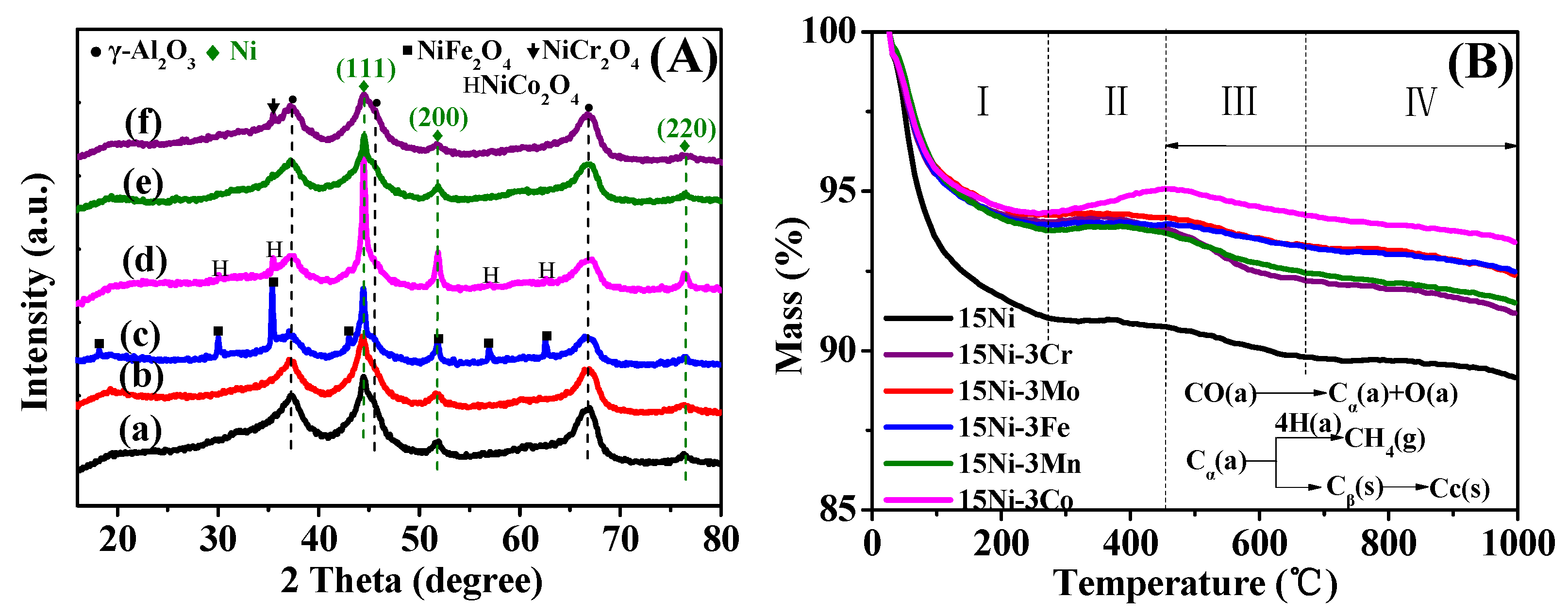
Figure 6A shows the XRD patterns of spent catalysts after performance tests. As is shown, the diffraction peaks of γ-Al2O3 support and active metal Ni still can be noted clearly compared with the XRD patterns of the reduced catalysts in Figure 2B. The crystal size of Ni (111) in the spent catalysts is calculated and listed in Table 1. By referring to the reduced catalysts, the Ni crystal size of all catalysts increases to various extents after performance tests, and particularly, there is almost no change in the size of Ni particles in the 15Ni-3Mn catalyst, indicating the slightest sintering degree of Ni particles and the best thermal stability. In addition to the Ni crystal size changes, some phases that did not exist in the reduced catalysts have newly emerged in the spent catalysts. Specifically, for 15Ni-3Fe, 15Ni-3Co and 15Ni-3Cr, the phases with the spinel structure (NiFe2O4, NiCr2O4 and NiCo2O4) are newly formed after the performance test. This type of spinel structure not only consumes part of the exposed Ni atoms, which would debase the H2 chemisorption ability in methanation, but also could enhance high temperature shift (HTS) [37]. As is proven by Figure 5B,C, the CH4 selectivity decreases while the CO2 growth rate remains at a relatively high level within the range of 350–400 °C for 15Ni-3Fe, 15Ni-3Co and 15Ni-3Cr.
The quantity of deposited carbon on the spent catalysts was gauged by TG analysis, and the obtained results are depicted in Figure 6B. Generally, the TG curves can be classified into four sections: (1) Section I: the weight loss between room temperature and 280 °C mainly derived from absorbed surface water and volatiles compound; (2) Section II: weight gain between 280 and 450 °C due to the oxidation of Ni particles [30]; (3) Section III: weight loss originated from the oxidation of deposited α-type carbon (Cα) between 450 and 670 °C; and (4) Section IV: weight loss ascribed to the oxidation of β-type carbon (Cβ) plus graphitic carbon (Cc) above 670 °C [24]. According to the literature [24,38], Cα is the active species formed by CO dissociation, which is the essential intermediate for the formation of methane, and Cβ is one kind of polymeric carbon species that can be produced by Cα reacting. Cc is normally generated at high temperatures that can be transformed from Cβ, whereas it is responsible for the deactivation of catalysts. Relevant simplified formulas are inserted in Figure 6B. The carbon deposition rate is also compiled in Table 2. As is shown, except for 15Ni-3Mn and 15Ni-3Cr, the other four catalysts have less carbon deposition and smaller carbon deposition rates. This may be due to their low activity as analyzed above. In terms of 15Ni-3Mn and 15Ni-3Cr catalysts with high activity, the former has less carbon deposition, as well as a lower carbon deposition rate than the latter, indicating better resistance of carbon formation for 15Ni-3Mn. Nevertheless, there is no diffraction peak in Figure 6A attributed to deposited carbon for all of the catalysts, probably owing to the limited amount of deposited carbon, which is below the detection limit or in the amorphous state.

2.3. Comparative Study on 15Ni-3Mn and 15Ni-3Cr

From the above analysis, we preliminarily concluded that both 15Ni-3Mn and 15Ni-3Cr have better activity than the other four catalysts for partial methanation coupling with WGS of biomass gas. In order to filter out the best candidate for industrial application, we carried out a series of comparative investigations on 15Ni-3Mn and 15Ni-3Cr.

2.3.1. Effect of H2/CO

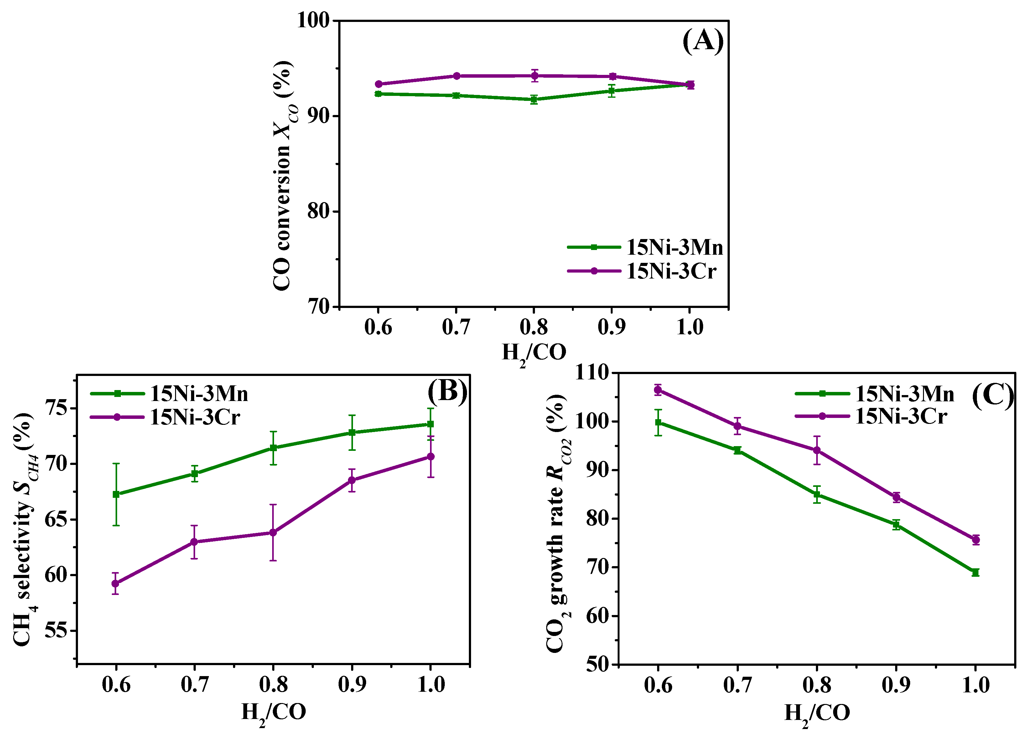
The effect of H2/CO on partial methanation coupling with WGS of biomass gas is summarized in Figure 7. As can be seen, for both 15Ni-3Mn and 15Ni-3Cr, the CH4 selectivity in Figure 7B is promoted while the CO2 growth rate in Figure 7C is impeded with increasing H2/CO. This is mainly due to increased H2 concentration that the larger H2/CO incurs, which is favorable for methanation, whereas detrimental for WGS. However, the changing trend of CO conversion for 15Ni-3Mn and 15Ni-3Cr exhibits an adverse pattern. As Figure 7A shows, it is obvious that CO conversion for 15Ni-3Mn first decreases and then increases with further increasing H2/CO, of which 91.7% CO conversion is obtained at H2/CO = 0.8. While for 15Ni-3Cr, CO conversion increases firstly and then decreases with H2/CO, along with the highest 94.3% CO conversion at H2/CO = 0.8. Considering that these two catalysts have same upward trend of CH4 selectivity and downward trend of the CO2 growth rate with H2/CO, we can safely conclude that for 15Ni-3Mn, methanation prevails over WGS, while for 15Ni-3Cr WGS surpasses methanation in the H2/CO range of 0.8–1.0. This adverse pattern may be caused by the difference of the synergy effect, as well as Ni dispersion and its interaction with the support between Ni-Mn and Ni-Cr.
Besides, according to Table 1, the Ni dispersion of 15Ni-3Mn is comparable with that of 15Ni-3Cr, but the H2 chemisorption ability of 15Ni-3Mn is larger than 15Ni-3Cr, which may account for the constantly higher CH4 selectivity of 15Ni-3Mn than that of 15Ni-3Cr in the whole range of H2/CO, further indicating that the former catalyst has better adaptability to various H2/CO conditions and is more eligible for industrial application.

2.3.2. Effect of H2O/CO

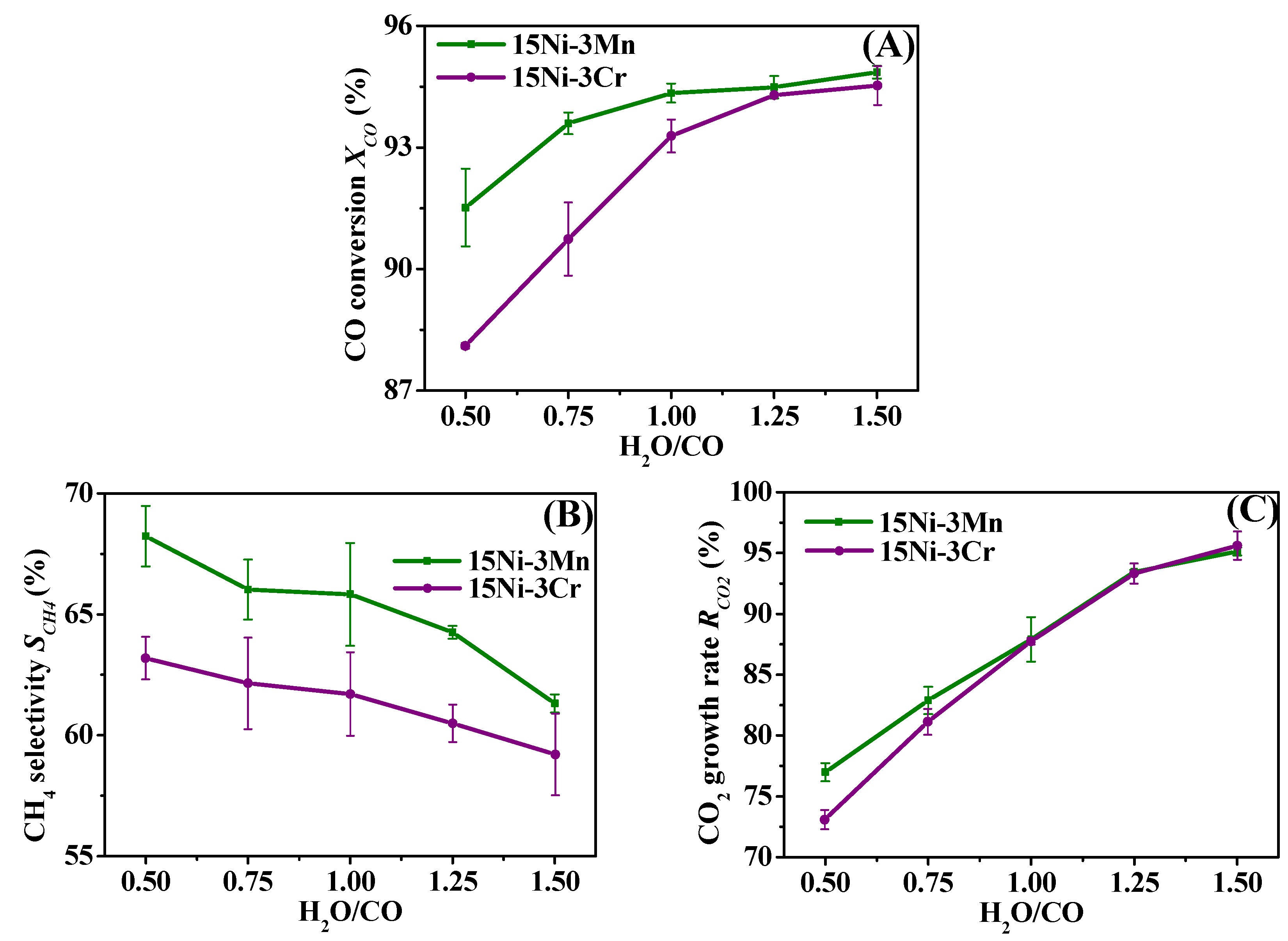
H2O plays an important role in the partial methanation coupling with WGS of biomass gas since it is not only the reactant of WGS reaction, but also serves as the product of methanation. Its dual identity makes it worthwhile to probe the effect of H2O/CO on catalytic performance, and the results are shown in Figure 8. As displayed in Figure 8B and Figure 8C, both 15Ni-3Mn and 15Ni-3Cr show a downward trend of CH4 selectivity, while an upward tendency of the CO2 growth rate as a function of H2O/CO. Hence, we can conclude that H2O could inhibit partial methanation, but otherwise promote the WGS reaction. As for its integrated influence on catalytic performance, it can be explicitly seen in Figure 8A that the CO conversion increases with H2O/CO, indicating that H2O favors WGS reaction over methanation. In addition, despite the comparable CO2 growth rate and CO conversion at high water content (1.0–1.5 H2O/CO) for both catalysts, 15Ni-3Mn presents better CH4 selectivity than 15Ni-3Cr, implying that the Mn species is more competent than Cr as the second component in the Ni-M bicomponent catalyst since the former is more efficient in converting CO to CH4.

2.3.3. Heating Value Analysis

The urban gas has to be of a certain heating value before it is transported in a pipeline to downstream residents. As mentioned previously, biomass gas after partial methanation coupling with WGS needs subsequent removal of CO2 in order to satisfy the heating value standard of urban gas. Apart from traditional upgrading technologies (e.g., water scrubbing, chemical and physical scrubbing and membrane adsorption), there are plentiful reported literature works concerning CO2 removal, such as the low-temperature CO2 removal process [39], pressure/vacuum swing adsorption using improved 13X zeolite [40] and using activated carbon as the adsorption bed layer in the pressure swing adsorption (PSA) unit [41]. Thus, it is practical to construct a CO2 removal unit as the gas upgrading segment with WGS plus the methanation unit as portrayed in Figure 1. Figure 9 displays the lower heating value of biomass gas under different conditions. It can be seen that the lower heating value increased after removing part of the CO2 due to the enhanced concentration of combustible components, such as H2, CO and CH4. Besides, after removing 30% CO2, the lower heating value for both catalysts is beyond 10 MJ∙Nm−3, which completely reaches the Type II standard of the Chinese National Standard GB/T 13612-2006 corresponding to manufactured gas (dotted line in Figure 9). Moreover, biomass gas catalyzed by 15Ni-3Mn steadily presents a higher heating value than 15Ni-3Cr, suggesting that 15Ni-3Mn is more suited for industrial application in converting low H2/CO ratio biomass gas to urban gas.

2.3.4. SEM Analysis after Comparative Study

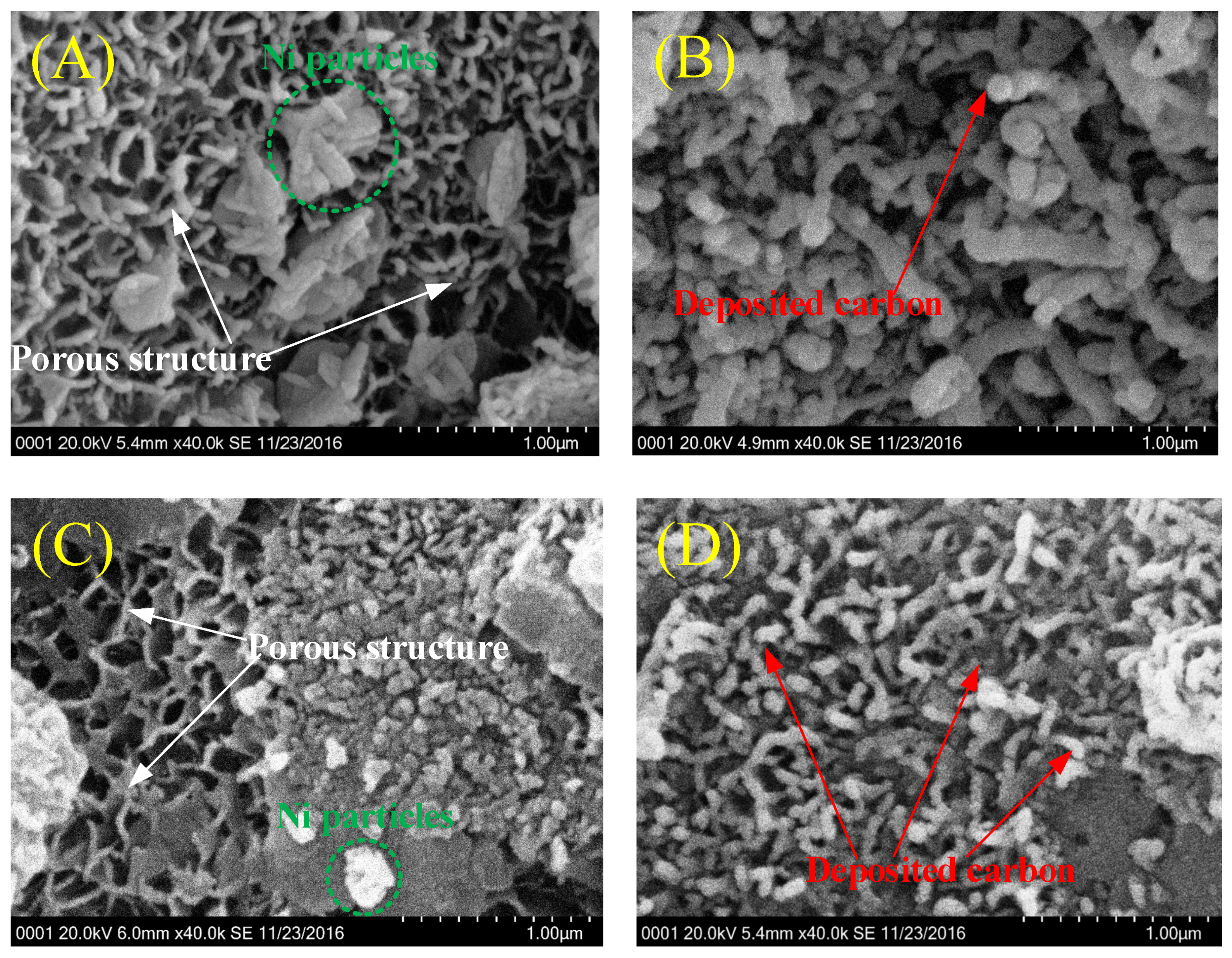
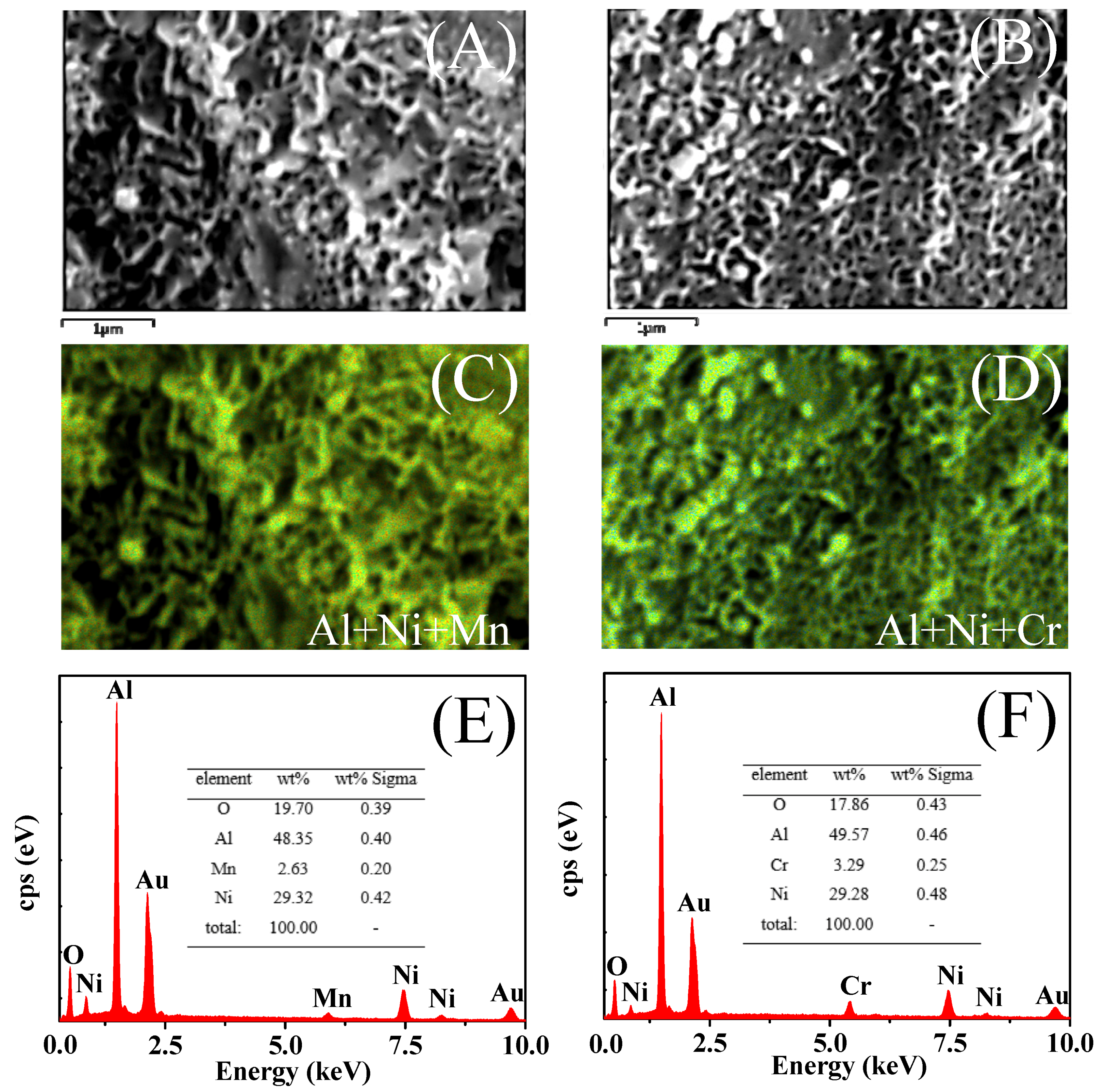
The structures of the two compared catalysts were further analyzed by SEM and EDS analysis. As Figure 10A,C presents, both reduced catalysts display a porous structure belonging to the Al2O3 support with a large specific surface area, which provides prerequisites for highly dispersed Ni particles and the second component. Besides, it can be clearly seen that Ni nanoparticles (possibly mixed with the second component) are distributed on the support surface without showing large aggregations, indicating the high dispersion that is consistent with the H2-TPD results in Table 1. Figure 11 displays the total elemental mapping images and corresponding EDS analysis of the two catalysts. As can be seen in Figure 11E,F, the Ni content of both catalysts is higher than the prepared content due to the limitation of EDS as a surface analysis technology instead of bulk analysis. The bulk content is listed in Table 1 based on ICP detection. Moreover, according to the elemental mapping images in Figure S4, for 15Ni-3Mn and 15Ni-3Cr, Al, Ni and Mn/Cr species are all in a homogeneous distribution, which is consistent with both a smaller Ni particles size derived from XRD analysis and the larger H2 adsorption amount in Table 1, further conforming their high dispersion on the support. The relative amount can be judged from their density in mapping images with a sequence of Al > Ni > Mn ≈ Cr, which is in accordance with the prepared content.
After the comparative study, carbon filaments and whiskers can be observed on the surface of both catalysts (Figure 10B,D). However, the amount of deposited carbon for 15Ni-3Cr is apparently larger than that for 15Ni-3Mn, which could be proven by TG analysis in Table 2. As is well known, deposited carbon is responsible for blocking support pores and covering active components, leading to a decreased catalytic activity. Thus, due to more deposited carbon, 15Ni-3Cr is less active than 15Ni-3Mn during the comparative study.

2.4. Stability of 15Ni-3Mn Catalyst

Through the comparative study, we found out that 15Ni-3Mn performs better than 15Ni-3Cr over a wide range of H2/CO and H2O/CO, impelling us to select 15Ni-3Mn as the best candidate for partial methanation coupling with WGS of low H2/CO ratio biomass gas into urban gas. However, from the industrial and engineering perspective, the catalyst must withstand start/stop cycles and have a desirable lifetime. As a result, in this section, we designed a start/stop cycle test and a lifetime test on the 15Ni-3Mn catalyst with the purpose of examining its performance in practical occasions. In the start/stop cycle test, the 15Ni-3Mn catalyst is confronted with continuous start-up/cessations of the engine. The series of cycles were realized by firstly cooling the system down to room temperature and then passing the reaction feed gas including steam through the catalyst bed for 30 min. Finally, the system was reheated to the chosen temperature of 350 °C [22]. The condensed water, which is located in the pore of catalyst, is considered as one of the harshest conditions for catalysts.
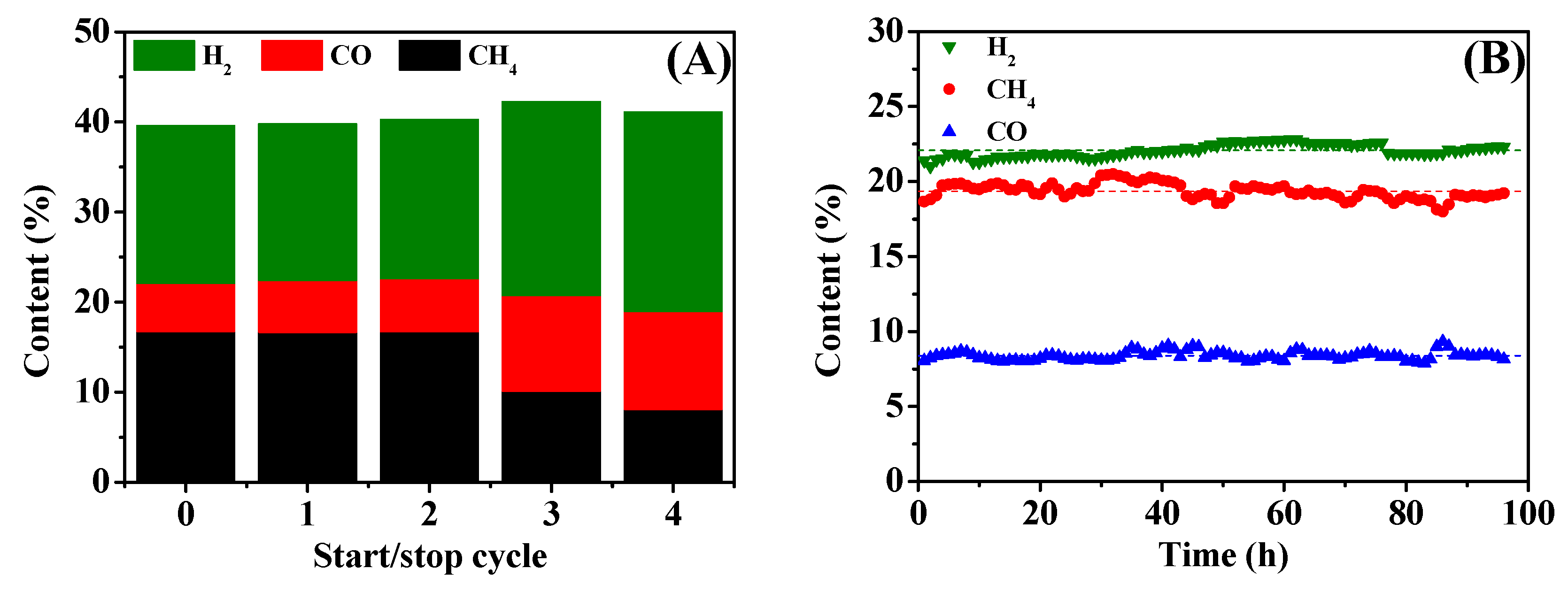
The heating value of urban gas is closely associated with the content of combustible components, such as H2, CO and CH4; thus, we concentrate on their content in the outlet. The experimental result in Figure 12A revealed that during the former two stop/cycles (Stop/Cycles 1 and 2), the content of H2, CO and CH4 remained as the state without shutdown (Stop/Cycle 0), indicating that the 15Ni-3Mn catalyst is robust to some extent. However, in Stop/Cycles 3 and 4, the content of CH4 decreased and CO increased, suggesting a deactivation in the 15Ni-3Mn catalyst. This may be due to destruction in the porous structure of the support and a wastage of active components caused by excessive condensed water. Nevertheless, this start/stop cycle test demonstrated indirectly that frequent shutdowns have a negative effect on the performance of catalyst, and we should keep systematic continuity as much as possible.
The lifetime test is considerably critical in the appraisal of catalyst, and a catalyst with good stability is crucial for industrial processes. Figure 12B presents the lifetime test results of the 15Ni-3Mn catalyst carried out at 350 °C, H2/CO = 0.8 and H2O/CO = 1. It can be seen that during the nearly 100-h lifetime test, the content of H2, CO and CH4 in the outlet gas remains relatively stable and basically fluctuates over the average value (dashed line in Figure 12B), suggesting that the 15Ni-3Mn catalyst could work with a satisfying stability over an extended period. This may be because the added Mn species could inhibit the rapid loss of specific surface area caused by Ni sintering (Table 1) and decrease the rate of carbon deposition (Table 2). Similar results are also reported elsewhere [30,42,43]. The mean content of H2 is 22.07% accompanied by 19.35% CH4 and 8.37% CO on average. In addition, the content of CO is below 10%, which could guarantee the safety requirements for downstream residents. The coexistence of H2 and CH4 with a high concentration demonstrates that the 15Ni-3Mn catalyst could splendidly catalyze partial methanation coupling with WGS of biomass gas, which exposes its great industrial potential.

2.5. Synergy Effect between Ni and MnOx Species

On the basis of the above results and discussions, a process of partial methanation coupling with WGS of biomass gas catalyzed by Ni-Mn bicomponent catalyst is outlined in Figure 13. As it illustrates, highly dispersed Ni particles and MnOx species serve as active sites for CO hydrogenation, as well as WGS. Compared to monometallic 15Ni catalyst, the addition of MnOx species on the one hand weakens the interaction between NiO and the Al2O3 support, which facilitates the reduction of NiO particles, while on the other hand increases the dispersion of reduced Ni, as well as the H2 uptake, leading to an increased activity for methanation. Moreover, the addition of MnOx species could enhance the WGS reaction, demonstrating an outstanding synergy effect between Ni and MnOx species. Compared to CrOx species, MnOx species could also inhibit the rate of carbon deposition, showing its better anti-coking ability when submitted to various H2/CO and H2O/CO situations. Finally, the synergy effect between Ni and MnOx species presents a nonlinear relationship with the amount of Mn addition, and there exists an optimal value, as shown in Figure S5.

3. Materials and Methods

3.1. Catalyst Preparation

The supported nickel-based bicomponent catalysts were prepared by the incipient wetness co-impregnation method. The γ-Al2O3 granular support (particle size: 2–3 mm) (Henan Chuangmei Environmental Protection Co., Ltd., Gongyi, China) was first pretreated by drying in an electric oven at 110 °C for 12 h, so as to remove the adsorbed impurities. Then, a precalculated amount of solution containing Ni(NO3)2·6H2O and the second metal salt, such as (NH)4Mo7O24·4H2O, Fe(NO3)2·9H2O, Co(NO3)2·6H2O, Mn(NO3)2·4H2O and Cr(NO3)2·9H2O, was mixed with the support material. All chemicals mentioned above were commercially provided by Sinopharm Chemical Reagent Co., Ltd. (Shanghai, China) and were of analytical purity. In order to obtain catalysts with uniformly-dispersed bicomponent Ni-M species (M = Mo, Fe, Co, Mn or Cr), the heterogeneous mixture was kept in a water bath at 60 °C for 12 h. Later, the samples were dried at 110 °C and calcined by a temperature programmed muffle furnace at 450 °C for 4 h. The nominal load of nickel in each of the acquired catalyst is 15 wt %, and that of the second metal is 3 wt %, unless noted elsewhere. For convenience, the abbreviations of the catalysts in this work are denoted as 15Ni-3M. 15Ni catalyst was also prepared in the same manner for reference.

3.2. Catalyst Characterizations

Inductively-coupled plasma (ICP) atomic emission spectrometry (Optima5300DV, PerkinElmer Instrument, Waltham, MA, USA) was used to determine the real contents of loaded metal in the as-prepared catalysts. N2 isothermal adsorption at −196 °C was analyzed using an automated gas adsorption analyzer (BELSORP-Mini, Osaka, Japan) in order to calculate the specific surface area according to the BET method and the pore size distribution by the BJH (Barrett-Joyner-Halenda) method. Powder X-ray diffraction (XRD) patterns were recorded by an X-ray diffractometer (Smart Lab, Tokyo, Japan) with Cu Kα radiation under a 0.02° scanning step and 20°∙min−1 scanning speed operated at 40 kV and 100 mA. The wavelength λ was 0.154 nm, and the scanning 2θ angle range was from 20°–80°.
H2-TPR and H2-TPD characterizations were carried out on an automated chemisorption analyzer (chemBET pulsar TPR/TPD, Quantachrome, Boynton Beach, FL, USA). For the H2-TPR test, typically, a 0.10 g sample was first placed at 300 °C for 1 h under Ar flow to remove moisture and impurities as the pretreatment. Following, the sample was cooled down to room temperature and reheated to 1000 °C at 10 °C∙min−1 under the flow of a 10 vol % H2/Ar mixture gas (40 mL∙min−1). The outlet signal was recorded continuously by a thermal conductivity detector (TCD) detector (Shimadzu Corporation, Kyoto, Japan). For the H2-TPD test, a 0.20 g sample was initially reduced in situ by H2 flow and subsequently cooled down to room temperature and saturated with H2 for 1 h. After the physically adsorbed H2 was removed by purging with Ar for 2 h, the sample was subsequently heated to 800 °C at a ramping rate of 10 °C∙min−1 in Ar flow (30 mL∙min−1). Likewise, the released H2 was detected continuously as a function of increasing temperature by a TCD detector. The dispersion of Ni was calculated based on the volume of chemisorbed H2 using the simplified equation referring to the literature [44]:
D ( % ) = 100 × 2 × V a d × M × SF m × P × V m × d r
where Vad (mL) is the volume of chemisorbed H2 in the TPD measurement at standard temperature and pressure (STP) conditions; M is the molecular weight of Ni (58.69 g∙mol−1); SF is the stoichiometric factor, which originates from the assumption of adsorption stoichiometry H/Ni = 1:1; m is the mass of the sample (g); P is the weight fraction of Ni in the sample determined by ICP; Vm is the molar volume of H2 (22.4 L∙mol−1) at STP; and dr is the reduction degree of Ni calculated on the basis of H2-TPR.
The properties and the amount of carbon deposits over spent catalysts were investigated through thermogravimetric (TG) analysis (NETZSCH STA 409 PC/PG, NETZSCH, Selb, Germany). The sample was heated in flowing air from room temperature to 1000 °C at a heating rate of 10 K∙min−1. The morphology of catalyst samples was determined by a HITACHI S-4800 scanning electron microscopy (SEM) operated at 5 kV with an energy dispersive X-ray spectroscopy (EDS) detector for elemental analysis.

3.3. Catalyst Testing

The catalyst testing was carried out in a continuous fixed-bed reactor equipped with a stainless steel tube (inner diameter: 50 mm, length: 1000 mm) at 0.1 MPa and a temperature range of 300–400 °C. In a typical catalyst test, the reactor with 50 mL of catalysts was initially heated to 450 °C (heating rate: 4 °C∙min−1) in N2 flow, and then the gas flow was switched to pure H2 (Gas Hour Space Velocity (GHSV): 1000 h−1) for catalyst reduction at the same temperature for 4 h. After the reduction period was finished, the reactor was cooled down to 250 °C, and the feed gas was switched to dry reactant gas flow with a composition of 20% CO2, 8% N2 and 0.6–1.0 H2/CO (total GHSV: 2000 h−1); and the additional required steam is based on the molar flow ratio of H2O and CO (0.5–1.0 H2O/CO). The outlet gas was analyzed by a Shimadzu GC2018 gas chromatography (Shimadzu Corporation, Kyoto, Japan) equipped with a 3 m Porapak Q column and a 2 m molecular sieve column, of which helium was used as the carrier gas. The concentrations of H2, CO2, N2, CH4 and CO were analyzed by a TCD, while C2H4 and C2H6 were analyzed by a flame ionization detector (FID, Shimadzu Corporation, Kyoto, Japan). This combination of two detectors allowed highly sensitive analysis of all components in the gas mixture. The detailed experimental setup is displayed in Figure S1.
The percentage conversion of CO (XCO) was calculated using Equation (4) to determine the overall catalytic activity. The CH4 selectivity (SCH4) and CO2 growth rate (RCO2) were determined using Equations (5) and (6) to measure the degree of methanation and WGS, respectively.
X CO ( % ) = ( [ F CO ] in [ F CO ] out ) / [ F CO ] i n × 100
S CH 4 ( % ) = [ F CH 4 ] out / ( [ F CO ] in + [ F CO 2 ] in [ F CO ] out [ F CO 2 ] out ) × 100
R CO 2 ( % ) = ( [ F CO 2 ] out [ F CO 2 ] in ) / [ F CO 2 ] in
where F is the molar flow of the inlet and outlet species.

4. Conclusions

Partial methanation coupling with WGS of low H2/CO ratio biomass gas into urban gas was investigated over γ-Al2O3-supported Ni-M (M = Mo, Fe, Co, Mn or Cr) catalysts. The bicomponent catalysts with fixed 15 wt % Ni and 3 wt % M were prepared by the co-impregnation method and further characterized by N2 isothermal physisorption, XRD, H2-TPR, H2-TPD and SEM. The comprehensive results of the characterization analysis, performance tests and comparative study showed that:
(1)
15Ni-3Mo, 15Ni-3Fe and 15Ni-3Co catalysts present lower CO conversion, CH4 selectivity and CO2 growth rate than one-component 15Ni catalyst, mainly due to their low Ni dispersion and weak H2 chemisorption ability with the addition of the second component, indicating the deficient synergy effect between Mo/Fe/Co and active Ni particles.
(2)
Though both 15Ni-3Mn and 15Ni-3Cr have relative high Ni dispersion and small Ni particle size, as well as comparable H2 chemisorption ability, 15Ni-3Mn is more suitable for our use due to its lower carbon deposition rate, smaller Ni sintering degree and wider adaptability to various H2/CO and H2O/CO conditions in comparison with 15Ni-3Cr.
(3)
15Ni-3Mn is robust to some extent during the start/stop cycle test and has satisfactory stability during a nearly 100-h lifetime test, showing its qualification for industrial and engineering use.
(4)
The lower heating value of the low H2/CO ratio biomass gas catalyzed by 15Ni-3Mn through partial methanation coupling with WGS could be over 10 MJ∙Nm−3, which is eligible as urban gas for downstream users.
(5)
MnOx species as an additive or second component cooperate well with Ni, for increasing methanation activity, as well as enhancing WGS reaction, indicating its favorable synergy effect with active Ni particle.

Supplementary Materials

The following are available online at https://www.mdpi.com/2073-4344/7/2/51/s1: Figure S1: Schematic diagram of catalyst testing. Figure S2: N2 adsorption isotherms (A) and PSD curves (B) of the support and as-prepared catalysts: (a) γ-Al2O3, (b) 15Ni, (c) 15Ni-3Mo, (d) 15Ni-3Fe, (e) 15Ni-3Co, (f) 15Ni-3Mn and (g) 15Ni-3Cr. Figure S3: XRD patterns of the γ-Al2O3 support: (a) before calcination and (b) after calcination at 450 °C for 4 h. Table S1: Detailed data of deconvolved TPR profiles. Figure S4: Elemental mapping images of reduced catalysts: (A,C,E) 15Ni-3Mn; (B,D,F) 15Ni-3Cr. Figure S5: Effect of Mn loading in 15Ni catalyst on the partial methanation coupling with WGS at 350 °C, H2/CO = 0.8 and H2O/CO = 1.

Acknowledgments

The financial support to the reported research by the International S & T Cooperation Program of China (ISTCP, 2014DFE70150) is gratefully acknowledged.

Author Contributions

Baosheng Jin, Min Song and Xinxin Dong conceived of and designed the experiments. Xinxin Dong, Zheng Zhou and Xu Yang performed the experiments. Xinxin Dong analyzed the data. Zheng Zhou and Xu Yang contributed reagents/materials/analysis tools. Xinxin Dong wrote the paper.

Conflicts of Interest

The authors declare no conflict of interest.

References

  1. Kopyscinski, J.; Schildhauer, T.J.; Biollaz, S.M.A. Production of synthetic natural gas (SNG) from coal and dry biomass-A technology review from 1950 to 2009. Fuel 2010, 89, 1763–1783. [Google Scholar] [CrossRef]
  2. Berrueco, C.; Recari, J.; Abelló, S.; Farriol, X.; Montané, D. Experimental Investigation of Solid Recovered Fuel (SRF) Gasification: Effect of Temperature and Equivalence Ratio on Process Performance and Release of Minor Contaminants. Energy Fuels 2015, 29, 7419–7427. [Google Scholar] [CrossRef]
  3. Yu, H.; Li, Z.; Yang, X.; Jiang, L.; Zhang, Z.; Chen, D. Experimental research on oxygen-enriched gasification of straw in an entrained-flow gasifier. J. Renew. Sustain. Energy 2013, 5, 053127. [Google Scholar] [CrossRef]
  4. Kwapinska, M.; Xue, G.; Horvat, A.; Rabou, L.P.L.M.; Dooley, S.; Kwapinski, W.; Leahy, J.J. Fluidized Bed Gasification of Torrefied and Raw Grassy Biomass (Miscanthus ×gigantenus). The Effect of Operating Conditions on Process Performance. Energy Fuels 2015, 29, 7290–7300. [Google Scholar] [CrossRef]
  5. Biagini, E.; Barontini, F.; Tognotti, L. Gasification of agricultural residues in a demonstrative plant: Vine pruning and rice husks. Bioresour. Technol. 2015, 194, 36–42. [Google Scholar] [CrossRef] [PubMed]
  6. Wang, Z.; He, T.; Qin, J.; Wu, J.; Li, J.; Zi, Z.; Liu, G.; Wu, J.; Sun, L. Gasification of biomass with oxygen-enriched air in a pilot scale two-stage gasifier. Fuel 2015, 150, 386–393. [Google Scholar] [CrossRef]
  7. Bukur, D.B.; Todic, B.; Elbashir, N. Role of water-gas-shift reaction in Fischer-Tropsch synthesis on iron catalysts: A review. Catal. Today 2016, 275, 66–75. [Google Scholar] [CrossRef]
  8. Haro, P.; Johnsson, F.; Thunman, H. Improved syngas processing for enhanced Bio-SNG production: A techno-economic assessment. Energy 2016, 101, 380–389. [Google Scholar] [CrossRef]
  9. Gao, J.; Qing, L.; Gu, F.; Liu, B.; Zhong, Z.; Su, F. Recent advances in methanation catalysts for the production of synthetic natural gas. RSC Adv. 2015, 5, 22759–22776. [Google Scholar] [CrossRef]
  10. Sener, C.; Wesley, T.S.; Alba-Rubio, A.C.; Kumbhalkar, M.D.; Hakim, S.H.; Ribeiro, F.H.; Miller, J.T.; Dumesic, J.A. PtMo Bimetallic Catalysts Synthesized by Controlled Surface Reactions for Water Gas Shift. ACS Catal. 2016, 6, 1334–1344. [Google Scholar] [CrossRef]
  11. Zhu, M.; Wachs, I.E. Iron-Based Catalysts for the High-Temperature Water-Gas Shift (HT-WGS) Reaction: A Review. ACS Catal. 2016, 6, 722–732. [Google Scholar] [CrossRef]
  12. Ahn, C.; Jeong, D.; Cho, J.M.; Na, H.; Jang, W.; Roh, H.; Choi, J.; Um, S.H.; Bae, J.W. Water gas shift reaction on the Mn-modified ordered mesoporous Co3O4. Microporous Mesoporous Mater. 2016, 221, 204–211. [Google Scholar] [CrossRef]
  13. He, R.; Wang, D.; Zhi, K.; Wang, B.; Zhong, H.; Jiang, H.; Li, N.; Liu, Q. Cu-Mn catalysts modified by rare earth lantnaum for low temperature water-gas shift reaction. J. Rare Earths 2016, 34, 994–1003. [Google Scholar] [CrossRef]
  14. Xiao, Y.; Wu, X.; Liu, S.; Wan, J.; Li, M.; Weng, D.; Tong, C. Modification of PdO/CeO2–ZrO2 catalyst by MnOx for water–gas shift reaction: Redox property and valence state of Pd. J. Mater. Sci. 2016, 51, 5377–5387. [Google Scholar] [CrossRef]
  15. Chianese, S.; Loipersböck, J.; Malits, M.; Rauch, R.; Hofbauer, H.; Molino, A.; Musmarra, D. Hydrogen from the high temperature water gas shift reaction with an industrial Fe/Cr catalyst using biomass gasification tar rich synthesis gas. Fuel Process. Technol. 2015, 132, 39–48. [Google Scholar] [CrossRef]
  16. Ma, S.; Tan, Y.; Han, Y. Water-gas shift coupling with methanation over MOx modified nanorod-NiO/γ-Al2O3 catalysts. J. Ind. Eng. Chem. 2011, 17, 723–726. [Google Scholar] [CrossRef]
  17. Mei, Z.; Li, Y.; Fan, M.; Argyle, M.D.; Tang, J. The effects of bimetallic Co–Ru nanoparticles on Co/RuO2/Al2O3 catalysts for the water gas shift and methanation. Int. J. Hydrog. Energy 2014, 39, 14808–14816. [Google Scholar] [CrossRef]
  18. Ding, M.; Tu, J.; Zhang, Q.; Wang, M.; Tsubaki, N.; Wang, T.; Ma, L. Enhancement of methanation of bio-syngas over CeO2-modified Ni/Al2O3 catalysts. Biomass Bioenergy 2016, 85, 12–17. [Google Scholar] [CrossRef]
  19. Hu, D.; Gao, J.; Ping, Y.; Jia, L.; Gunawan, P.; Zhong, Z.; Xu, G.; Gu, F.; Su, F. Enhanced Investigation of CO Methanation over Ni/Al2O3 Catalysts for Synthetic Natural Gas Production. Ind. Eng. Chem. Res. 2012, 51, 4875–4886. [Google Scholar] [CrossRef]
  20. Kumar, J.; Deo, G.; Kunzru, D. Preferential oxidation of carbon monoxide on Pt/γ-Al2O3 catalyst: Effect of adding ceria and nickel. Int. J. Hydrog. Energy 2016, 41, 18494–18501. [Google Scholar] [CrossRef]
  21. Gao, Z.; Cui, L.; Ma, H. Selective methanation of CO over Ni/Al2O3 catalyst: Effects of preparation method and Ru addition. Int. J. Hydrog. Energy 2016, 41, 5484–5493. [Google Scholar] [CrossRef]
  22. Arbeláez, O.; Reina, T.R.; Ivanova, S.; Bustamante, F.; Villa, A.L.; Centeno, M.A.; Odriozola, J.A. Mono and bimetallic Cu-Ni structured catalysts for the water gas shift reaction. Appl. Catal. A 2015, 497, 1–9. [Google Scholar] [CrossRef]
  23. Bayat, N.; Rezaei, M.; Meshkani, F. Methane decomposition over Ni–Fe/Al2O3 catalysts for production of COx-free hydrogen and carbon nanofiber. Int. J. Hydrog. Energy 2016, 41, 1574–1584. [Google Scholar] [CrossRef]
  24. Liu, Q.; Zhong, Z.; Gu, F.; Wang, X.; Lu, X.; Li, H.; Xu, G.; Su, F. CO methanation on ordered mesoporous Ni–Cr–Al catalysts: Effects of the catalyst structure and Cr promoter on the catalytic properties. J. Catal. 2016, 337, 221–232. [Google Scholar] [CrossRef]
  25. Zhao, K.; Li, Z.; Bian, L. CO2 methanation and co-methanation of CO and CO2 over Mn-promoted Ni/Al2O3 catalysts. Front. Chem. Sci. Eng. 2016, 10, 273–280. [Google Scholar] [CrossRef]
  26. Lu, H.; Yang, X.; Gao, G.; Wang, J.; Han, C.; Liang, X.; Li, C.; Li, Y.; Zhang, W.; Chen, X. Metal (Fe, Co, Ce or La) doped nickel catalyst supported on ZrO2 modified mesoporous clays for CO and CO2 methanation. Fuel 2016, 183, 335–344. [Google Scholar] [CrossRef]
  27. Wang, R.; Li, Y.; Shi, R.; Yang, M. Effect of metal–support interaction on the catalytic performance of Ni/Al2O3 for selective hydrogenation of isoprene. J. Mol. Catal. A Chem. 2011, 344, 122–127. [Google Scholar] [CrossRef]
  28. Zhao, A.; Ying, W.; Zhang, H.; Hongfang, M.; Fang, D. Ni/Al2O3 catalysts for syngas methanation: Effect of Mn promoter. J. Nat. Gas Chem. 2012, 21, 170–177. [Google Scholar] [CrossRef]
  29. Zhang, J.; Xu, H.; Jin, X.; Ge, Q.; Li, W. Characterizations and activities of the nano-sized Ni/Al2O3 and Ni/La–Al2O3 catalysts for NH3 decomposition. Appl. Catal. A 2005, 290, 87–96. [Google Scholar] [CrossRef]
  30. Lu, X.; Gu, F.; Liu, Q.; Gao, J.; Jia, L.; Xu, G.; Zhong, Z.; Su, F. Ni–MnOx Catalysts Supported on Al2O3-Modified Si Waste with Outstanding CO Methanation Catalytic Performance. Ind. Eng. Chem. Res. 2015, 54, 12516–12524. [Google Scholar] [CrossRef]
  31. Rodriguez, J.A.; Chaturvedi, S.; Hanson, J.C.; Brito, J.L. Reaction of H2 and H2S with CoMoO4 and NiMoO4: TPR, XANES, Time-Resolved XRD, and Molecular-Orbital Studies. J. Phys. Chem. B 1999, 103, 770–781. [Google Scholar] [CrossRef]
  32. Jeong, D.; Jang, W.; Shim, J.; Roh, H. High temperature water–gas shift without pre-reduction over spinel ferrite catalysts synthesized by glycine assisted sol–gel combustion method. Int. J. Hydrog. Energy 2016, 41, 3870–3876. [Google Scholar] [CrossRef]
  33. Nikparsa, P.; Mirzaei, A.A.; Rauch, R. Impact of Na Promoter on Structural Properties and Catalytic Performance of CoNi/Al2O3 Nanocatalysts for the CO Hydrogenation Process: Fischer–Tropsch Technology. Catal. Lett. 2016, 146, 61–71. [Google Scholar] [CrossRef]
  34. Velu, S.; Gangwal, S. Synthesis of alumina supported nickel nanoparticle catalysts and evaluation of nickel metal dispersions by temperature programmed desorption. Solid State Ion. 2006, 177, 803–811. [Google Scholar] [CrossRef]
  35. Gatica, J. M.; Chen, X.; Zerrad, S.; Vidal, H.; Ali, A.B. Simultaneous water gas shift and methanation reactions on Ru/Ce0.8Tb0.2O2−x based catalysts. Catal. Today 2012, 180, 42–50. [Google Scholar] [CrossRef]
  36. Senanayake, S.D.; Evans, J.; Agnoli, S.; Barrio, L.; Chen, T.; Hrbek, J.; Rodriguez, J.A. Water-Gas Shift and CO Methanation Reactions over Ni–CeO2(111) Catalysts. Top. Catal. 2011, 54, 34–41. [Google Scholar] [CrossRef]
  37. Lee, M.S.; Lee, J.Y.; Lee, D.; Moon, D.J.; Lee, K. The effect of Zn addition into NiFe2O4 catalyst for high-temperature shift reaction of natural gas reformate assuming no external steam addition. Int. J. Hydrog. Energy 2012, 37, 11218–11226. [Google Scholar] [CrossRef]
  38. Bartholomew, C.H. Mechanisms of catalyst deactivation. Appl. Catal. A 2001, 212, 17–60. [Google Scholar] [CrossRef]
  39. Yousef, A.M.I.; Eldrainy, Y.A.; El-Maghlany, W.M.; Attia, A. Upgrading biogas by a low-temperature CO2 removal technique. Alex. Eng. J. 2016, 55, 1143–1150. [Google Scholar] [CrossRef]
  40. Campo, M.C.; Ribeiro, A.M.; Ferreira, A.F.P.; Santos, J.C.; Lutz, C.; Loureiro, J.M.; Rodrigues, A.E. Carbon dioxide removal for methane upgrade by a VSA process using an improved 13X zeolite. Fuel Process. Technol. 2016, 143, 185–194. [Google Scholar] [CrossRef]
  41. Lestinsky, P.; Vecer, M.; Navratil, P.; Stehlik, P. The removal of CO2 from biogas using a laboratory PSA unit: Design using breakthrough curves. Clean Technol. Environ. Policy 2015, 17, 1281–1289. [Google Scholar] [CrossRef]
  42. Guo, F.; Xu, J.; Chu, W. CO2 reforming of methane over Mn promoted Ni/Al2O3 catalyst treated by N2 glow discharge plasma. Catal. Today 2015, 256, 124–129. [Google Scholar] [CrossRef]
  43. Yao, L.; Zhu, J.; Peng, X.; Tong, D.; Hu, C. Comparative study on the promotion effect of Mn and Zr on the stability of Ni/SiO2 catalyst for CO2 reforming of methane. Int. J. Hydrog. Energy 2013, 38, 7268–7279. [Google Scholar] [CrossRef]
  44. Liu, Q.; Gao, J.; Zhang, M.; Li, H.; Gu, F.; Xu, G.; Zhong, Z.; Su, F. Highly active and stable Ni/γ-Al2O3 catalysts selectively deposited with CeO2 for CO methanation. RSC Adv. 2014, 4, 16094–16103. [Google Scholar] [CrossRef]
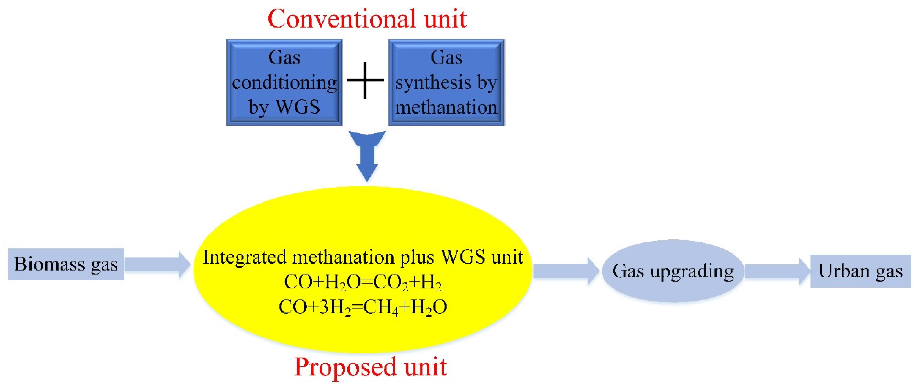
Figure 1. General scheme of the process chain from biomass gas to urban gas. WGS, water gas shift.
Catalysts 07 00051 g001
Figure 2. XRD patterns of the as-prepared catalysts (A) and reduced catalysts (B): (a) 15Ni, (b) 15Ni-3Mo, (c) 15Ni-3Fe, (d) 15Ni-3Co, (e) 15Ni-3Mn and (f) 15Ni-3Cr.
Catalysts 07 00051 g002
Figure 3. TPR profiles of the as-prepared catalysts (A) and (B).
Catalysts 07 00051 g003
Figure 4. H2-TPD curves of the reduced catalysts.
Catalysts 07 00051 g004
Figure 5. Catalytic performances of the reduced catalysts for partial methanation coupling with WGS at H2/CO = 0.8 and H2O/CO = 1: (A) CO conversion; (B) CH4 selectivity; and (C) CO2 growth rate.
Catalysts 07 00051 g005
Figure 6. XRD patterns (A) and TG curves (B) of spent catalysts after performance tests: (a) 15Ni, (b) 15Ni-3Mo, (c) 15Ni-3Fe, (d) 15Ni-3Co, (e) 15Ni-3Mn and (f) 15Ni-3Cr.
Catalysts 07 00051 g006
Figure 7. Effect of H2/CO on partial methanation coupling with WGS at 350 °C and H2O/CO = 1: (A) CO conversion; (B) CH4 selectivity; and (C) CO2 growth rate.
Catalysts 07 00051 g007
Figure 8. Effect of H2O/CO on partial methanation coupling with WGS at 350 °C and H2/CO = 0.8: (A) CO conversion; (B) CH4 selectivity; and (C) CO2 growth rate.
Catalysts 07 00051 g008
Figure 9. Lower heating value of biomass gas under different conditions. Condition 1 refers to the outlet state after partial methanation coupling with WGS at 350 °C, H2/CO = 0.8 and H2O/CO = 1. Conditions 2–4 refer to the assumed state, for which 30%, 40% and 50% CO2 is removed, respectively.
Catalysts 07 00051 g009
Figure 10. SEM (scanning electron microscope) images of reduced catalysts: (A) 15Ni-3Mn; (C) 15Ni-3Cr; and spent catalysts: (B) 15Ni-3Mn; (D) 15Ni-3Cr.
Catalysts 07 00051 g010
Figure 11. SEM images (A,B), corresponding total elemental mapping images (C,D) and EDS (energy dispersive spectroscopy) analysis (E,F) of reduced catalysts. ((A,C,E) for 15Ni-3Mn and (B,D,F) for 15Ni-3Cr).
Catalysts 07 00051 g011
Figure 12. Start/stop cycle test (A) and lifetime test (B) of 15Ni-3Mn catalyst at 350 °C, H2/CO = 0.8 and H2O/CO = 1.
Catalysts 07 00051 g012
Figure 13. Schematic of the synergy effect between Ni and MnOx species for partial methanation coupling with WGS.
Catalysts 07 00051 g013
Table 1. Physical and chemical properties of the support and catalysts.
SamplesNi wt % aM wt % aSBET (m2∙g−1) bVp (cm3∙g−1) cdp,peak (nm) dAverage Pore Size (nm) eNi Size (nm) fH2 Uptake (μmol∙g−1)D (%) gTOFCO (s−1) h
ReducedSpent
γ-Al2O3--241.460.343.826.62-----
15Ni14.6-179.150.313.727.0217.018.3385.036.10.0025
15Ni-3Mo13.72.7167.070.273.796.3516.517.1294.531.20.0024
15Ni-3Fe14.43.2162.180.293.687.2622.623.3235.121.20.0020
15Ni-3Co13.82.5160.130.283.687.0622.823.8342.327.10.0023
15Ni-3Mn14.73.1159.010.283.687.0313.213.4416.841.00.0040
15Ni-3Cr15.53.1179.960.273.797.1012.113.7395.542.80.0031
a Metal loading of as-prepared catalysts determined by inductively-coupled plasma (ICP). b Surface area of the support and as-prepared catalysts calculated using the BET (Brunauer-Emmett-Teller) method. c Pore volume of the support and as-prepared catalysts obtained from the volume of nitrogen adsorbed at relative pressure of 0.99. d Peak value of the pore size distribution (PSD) curves in Figure S2B. e Average pore size of the support and as-prepared catalysts derived from the PSD curves in Figure S2B. f Crystal size of Ni (111) derived from the Debye–Scherrer equation. g Ni dispersion calculated based on the H2-temperature programmed reduction (TPR) and H2-temperature programmed desorption (TPD) results. h Calculated based on the reaction condition of T = 350 °C, H2/CO = 0.8 and H2O/CO = 1.
Table 2. Carbon deposition data of spent catalysts after performance tests.
SamplesCarbon Deposition Rate a (mmol∙min−1)Carbon Deposition b (wt %)
15Ni4.8821.82
15Ni-3Mo6.4251.95
15Ni-3Fe3.8701.54
15Ni-3Co4.2121.69
15Ni-3Mn5.3052.40
15Ni-3Cr7.4503.06
a Average value of carbon deposition rates at five temperature spots in performance tests based on the carbon balance between inlet and outlet species. b Obtained from Section III and Section IV in the TG curves.