Article

The Influence of the Washcoat Deposition Process on High Pore Density Open Cell Foams Activation for CO Catalytic Combustion

by
Matteo Ambrosetti
1,
Riccardo Balzarotti
1,
Cinzia Cristiani
2,
Gianpiero Groppi
1 and
Enrico Tronconi
1,*
1
Dipartimento di Energia, Politecnico di Milano, Via La Masa 34, 20156 Milano, Italy
2
Dipartimento di Chimica, Materiali e Ingegneria Chimica “G. Natta”, Politecnico di Milano, Piazza Leonardo da Vinci 32, 20133 Milano, Italy
*
Author to whom correspondence should be addressed.
Catalysts 2018, 8(11), 510; https://doi.org/10.3390/catal8110510
Submission received: 28 September 2018 / Revised: 25 October 2018 / Accepted: 30 October 2018 / Published: 2 November 2018
(This article belongs to the Special Issue Structured Catalysts for Catalytic Processes Intensification)

Abstract

:
Spin coating was evaluated as alternative deposition technique to the commonly used dip coating procedure for washcoat deposition on high-porosity metallic substrates. By using spin coating, the washcoating of metallic open cell foams with very high pore density (i.e., 580 μm in cell diameter) was finely controlled. Catalytic performances of samples prepared with conventional dip coating and spin coating were evaluated in CO catalytic combustion in air, using palladium as active phase and cerium oxide as carrier. The incipient wetness method was used to prepare catalytic powder, which was dispersed by means of an acid-free dispersing medium. After washcoating, deposited layers were evaluated by optical microscopy and adhesion test. In comparison to dip-coated samples, the use of spin coating demonstrated better performances from both catalytic and coating quality points of view, highlighting the possibility of the industrial adoption of these supports for process intensification in several catalytic applications.

1. Introduction

The development of structured reactors is a topic of growing interest in heterogeneous catalysis, as it represents one of the most promising solutions to overcome heat and mass transfer limitations of traditional structured catalysts. Honeycombs represent the state-of-the-art solution for environmental processes like gas-exhaust after-treatment applications. These supports are characterized by a regular geometry where the flow enters parallel duct channels. Due to this geometry, the flow is segregated and the flow regime inside the channels is typically laminar, yielding to low pressure drops but at the same time moderate mass transfer rates. In contrast, open cell sponges are cellular materials characterized by a random geometry. They are constituted by a network of fully interconnected solid struts and open pores that are permeable to flow. These materials typically present high porosities of up to 95% and relatively high surface areas which are inversely proportional to their cell size [1]. In contrast to honeycombs, the flow field inside open cell foams is more complex, since a continuous formation/disruption of the boundary layer is present. Moreover, the flow is not segregated, and radial mixing is allowed. These aspects yield higher pressure drops with respect to honeycombs, but at the same time higher mass transfer coefficients are obtained [2]. To enable the intensification of environmental processes and to allow the design of more compact catalytic reactors, the adoption of high-PPI (pores per inch) foams is needed in order to have a comparable surface area with state-of-the-art honeycombs.
In structured reactors, catalytic material is fixed onto a continuous matrix, which can have different shapes, like honeycomb monoliths or open cell foams. In the literature, different procedures are reported to catalytically activate structured supports by depositing active phases [3]. The active phase can be directly deposited either onto a support surface (i.e., incorporation) or onto a high surface area carrier (i.e., washcoating) [4]. The activation via washcoat deposition is the most popular solution to enhance catalytic properties of structured supports, and it requires procedures to produce catalytically active powders, which are deposited onto a geometrical support surface. Among others, the incipient wetness method allows easy management of the active phase quantity and the production of highly dispersed metal phases on high surface area powders.
Washcoat thickness management is of paramount importance to obtain good catalytic performances. In this sense, a thin catalyst layer (tens of microns) is usually desired to be deposited onto structured supports to maximize performance. In this view, the dip-coating process is widely reported in the literature as the technique of choice for obtaining the best results in terms of cost, time, and effectiveness [5,6]. In order to improve the interaction between washcoat layer and support surface, pre-treatment procedures are carried out, either thermally or chemically. After coating deposition, additional thermal treatments are usually performed to consolidate the washcoat layer in its final form [7].
In order to properly manage the washcoating process, many parameters need to be carefully tuned. A proper management of slurry rheological properties is of paramount importance in order to control washcoat thickness and to obtain well-adhered washcoat layers. Generally speaking, low loads and high adhesion are usually obtained when low viscosity slurries are used, while high-viscosity formulations determine thicker washcoat layers but poor adhesion [4]. Rheological properties can be changed by modifying the formulation components (i.e., binder, dispersant, solvent, and powder particles size distribution) [5].
Dispersion stability is a mandatory requirement to obtain good-quality washcoats. Usually, dispersions are stabilized by using acidic solutions. During the process, H+ ions cover the powder surface and stability is thus achieved by surface charging [8]. Despite the good results that can be obtained by using this technique, some limitations are present, as in case of low surface area or chemically inert powders. Additionally, some active phases or supports may be altered in the presence of acidic solutions [9]. On the basis of these considerations, the use of organic dispersants has been investigated to properly stabilize catalyst powder dispersions [10]. Among others, glycerol and PVA (polyvinyl alcohol) have been evaluated as dispersant and binder, respectively [11]. Moreover, the same formulation has been proven to be effective for catalyst deposition on ceramic supports, namely ceramic honeycomb monoliths and sponges up to 40 PPI, for the oxy-steam reforming process [12,13].
During washcoating, slurry is usually entrained into the geometrical support due to its high porosity. Thus, a proper driving force needs to be used in order to remove excess slurry. In the literature, gas blowing has been widely used to control coating formation [14], and some examples of centrifugation are also present [15,16]. Less attention has been devoted to the investigation of spin coating for high-porosity supports [17]. For example, Zhang et al. reported results of spin-coating on carbon foams at different operating conditions [18].
Although washcoating topic has been extensively investigated in the literature, efforts still need to be spent to properly manage the washcoat formation process. This is even more evident when high-porosity supports are considered.
Regardless of the fact that these supports have demonstrated very promising properties in view of process intensification, few authors have used supports with more than 100 PPI (Pores Per Inch) for catalytic application and few details are present regarding active phase deposition [19,20]. These details are of paramount importance to finely control the washcoat deposition process, as high-porosity materials represent a great challenge due to their complex 3D structure that may severely induce pore clogging phenomena. C. Wang et al. proposed an evaporation-induced self-assembly (EISA) method for incorporating powder catalysts with 110 PPI metal matrices to form monolithic composite catalysts for CO selective methanation [21]. H. Yu et al. investigated the influence of material choice and activation procedure on 100 PPI open cell foams for methanol steam reforming and the catalytic combustion of methane [22,23]. Unfortunately, only brief details on the production procedure and washcoat characterization were reported. Recently, the electrodeposition of supported active phases on high-PPI FeCr alloy foams for CO oxidation [24] and for reforming applications [25] has been proposed as an alternative to conventional washcoating processes. Other activation procedures, such as galvanic exchange reaction [26,27] and modified wet chemical etching [28,29] were also proposed.
In view of these considerations, the goal of this work is the investigation of the use of spin coating as a valuable alternative to the highly consolidated dip-coating technique for washcoat deposition on substrates with complex geometry. Spin coating is a very promising technique to properly control the washcoating process and, to our knowledge, few works are present in the literature on high-porosity supports functionalization [30]. In particular, in this work high-porosity materials (nominal cell sizes equal to 1200 and 580 µm, which correspond to roughly 60 and 100 PPI by optical microscopy evaluations) were used as catalyst support for palladium on cerium oxide catalytic powders. Powders were dispersed by means of an acid-free dispersing medium based on water and organic compounds, and they were effectively deposited on thermally pretreated supports. Catalytic performances were evaluated in the CO catalytic combustion in air using a tubular lab-scale reactor. Foams with these cell diameters can enable the intensification of different environmental processes limited by external mass transport.

2. Results

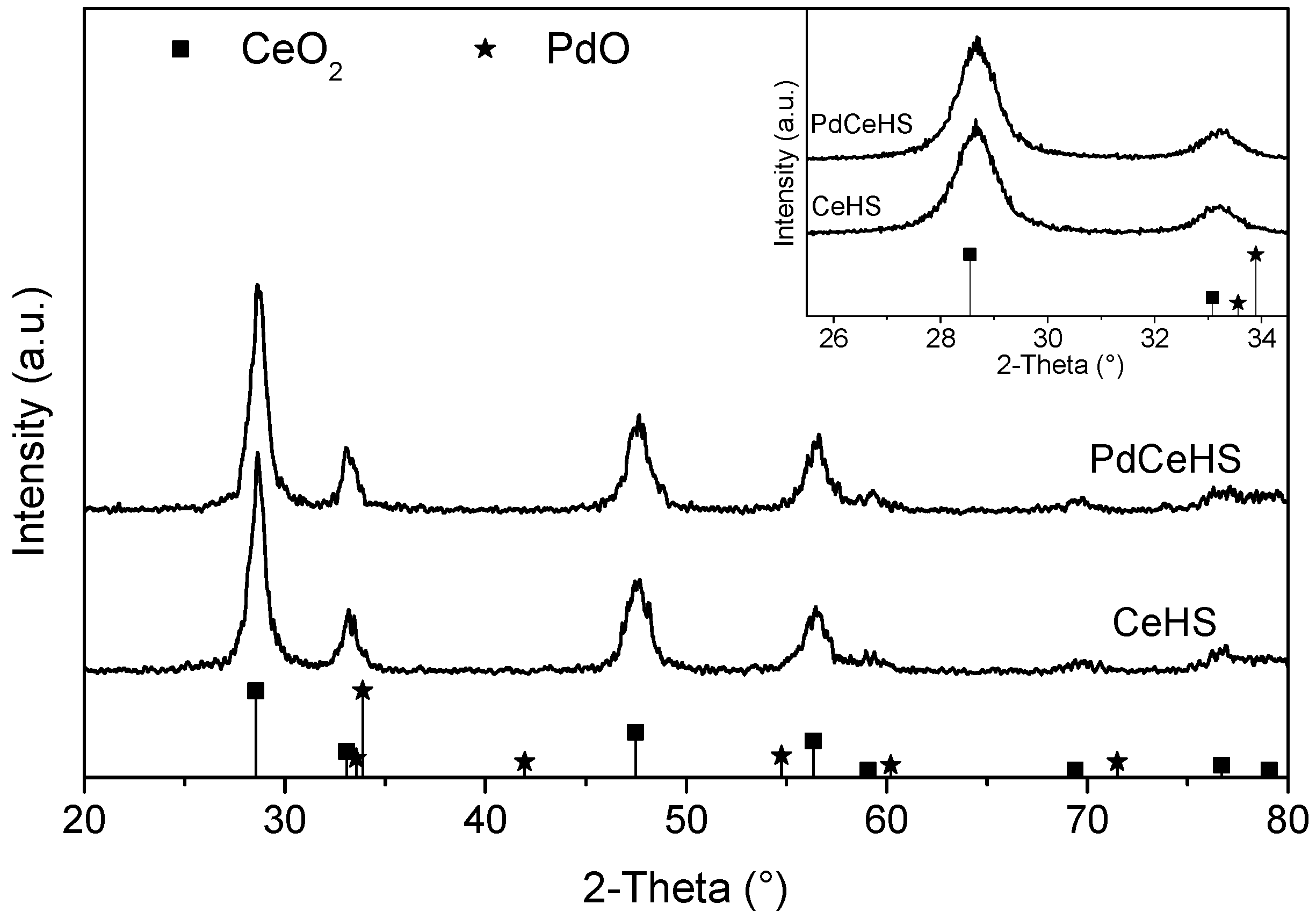
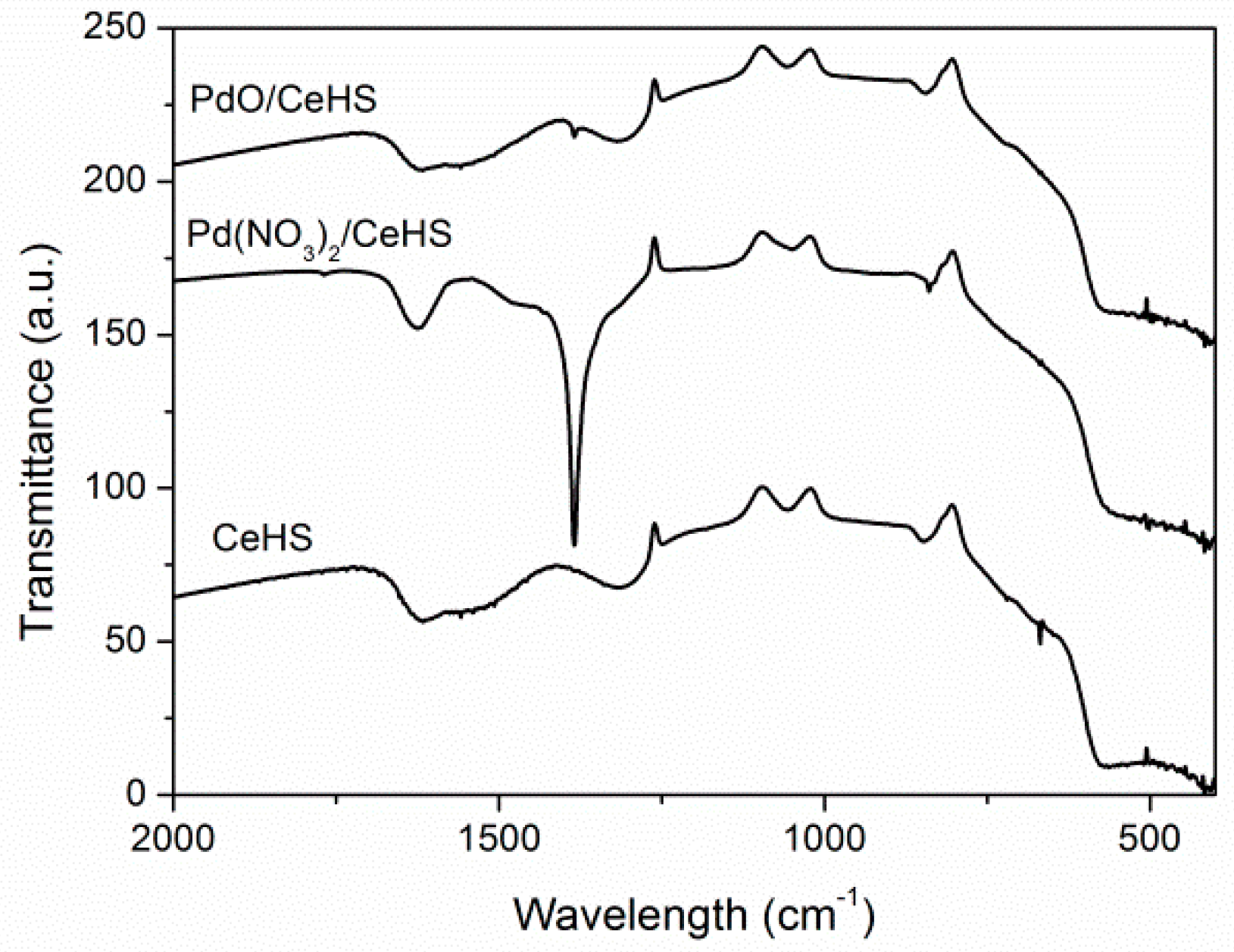
2.1. Catalyst Characterization

The bare carrier and the catalytic active powder were characterized in terms of surface area and pore volume. Results of BET analysis and Hg intrusion indicated a surface area of 80 m2∙g−1, while the pore volume was equal to 0.6 mL∙g−1. The latter was assumed as the parameter of choice to perform the dry-impregnation procedure. Results of the physical characterization of catalytic powders before and after palladium deposition are reported in the following. In particular, XRD diffractograms of CeHS (bare carrier) and PdCeHS (carrier with active phase) samples are shown in Figure 1.
The diffractograms of both samples corresponded to a fluorite-type CeO2 (PDF 034-0394) phase of comparable crystallinity, while no palladium oxide (PdO) reflections (PDF 043-1024) could be detected, possibly due to allow amount of palladium oxides and total peak overlapping with those of cerium oxide. In order to get information on the presence of PdO on the catalysts, Fourier transform infrared spectroscopic (FT-IR) and TG-DTG analyses were performed. The results of FT-IR analysis are shown in Figure 2.
From the FT-IR analysis, the presence of palladium species was confirmed although clearly manifested only in untreated catalyst (Pd(NO3)2/CeHS spectrum in Figure 2). Indeed, the sharp and intense reflection at 1380 cm−1 is characteristic of nitrate species, and therefore of Pd(NO3)2. This attribution was confirmed by the band disappearance upon catalyst calcination (Figure 2), proving the decomposition of palladium nitrate precursor to its final oxide form. Moreover, the overlapping of such a spectrum with that of the bare support suggested that no changes occurred in the CeO2 carrier during the calcination procedure for palladium nitrate decomposition.
In order to further confirm the presence of palladium in a quantitative way, thermogravimetric analysis was performed on PdCeHS powder. Thermograms were collected in air over two subsequent heating and cooling cycles from room temperature up to 1000 °C. A progressive weight loss was observed starting from 800 °C, which corresponds well to the temperature for PdO↔Pd0 decomposition on Ce-based carrier. Moreover, considering the cooling ramp, the typical hysteresis of palladium redox reversible transformation was also manifest, as reported in Reference [31]. By measuring weight loss and gain in correspondence of temperature hysteresis, a Pd0 content of 2.9% wt. was estimated, which is in very good agreement with the nominal one (3% wt.).
Finally results on Pd content were also in good accordance with SEM-EDS estimation, which indicated an average Pd0 content of 2.5% wt. ± 0.3% wt. (standard deviation is the result of five replicated measurements). For the sake of comparison, results of active phase quantification are shown in Table 1.

2.2. Rheological Behavior

PdCeHS powder was dispersed in HGP liquid medium (namely H-water, G-glycerol and P-polyvinyl alcohol solution) as reported in Section 3.3. Rheological measurements were performed on the obtained slurry to evaluate both the absolute viscosity and the rheological behavior. For the sake of comparison, the slurry obtained by dispersion of the bare carrier (CeHS) was also analyzed (Figure 3).
At a glance, different rheological behaviors were detected for the two samples. Indeed, a non-Newtonian more viscous behavior characterized the bare carrier, while a Newtonian and less viscous one was observed for the Pd-containing powder. As an example, at fixed shear rate of 10 s−1 (of interest for the selected coating procedures), the absolute viscosity shifted from 0.056 to 0.029 Pa∙s for CeHS and PdCeHS, respectively. Therefore, the presence of Pd ions, although in limited amount (3% wt.), was able to modify the rheological response of the bulk powder. This behavior has already been discussed in the literature for formulations of similar compositions in the case of carrier powders of lower surface area [32]. Accordingly, also in this case, the presence of the active phase increased powder apparent density, resulting in a decrease of particles concentration per dispersant unit volume. Therefore, the macroscopic effect consisted of the reduction of the slurry viscosity and a shift towards Newtonian behavior [33,34]. The effects of the nature of the powders’ surface (e.g., zero point charge and/or acidity) cannot be discarded, although they deserve a deeper investigation, which is not within the scope of the present paper.

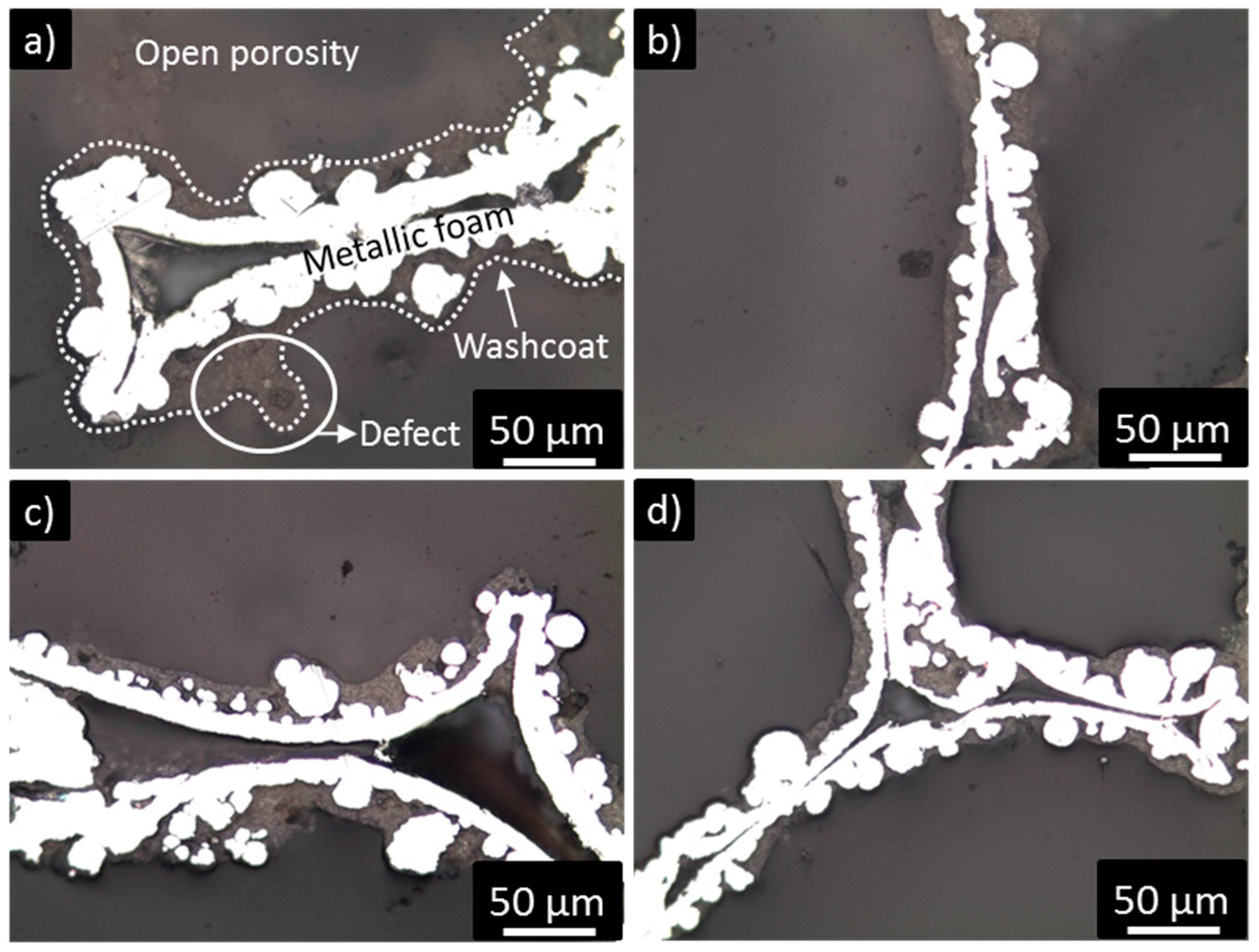
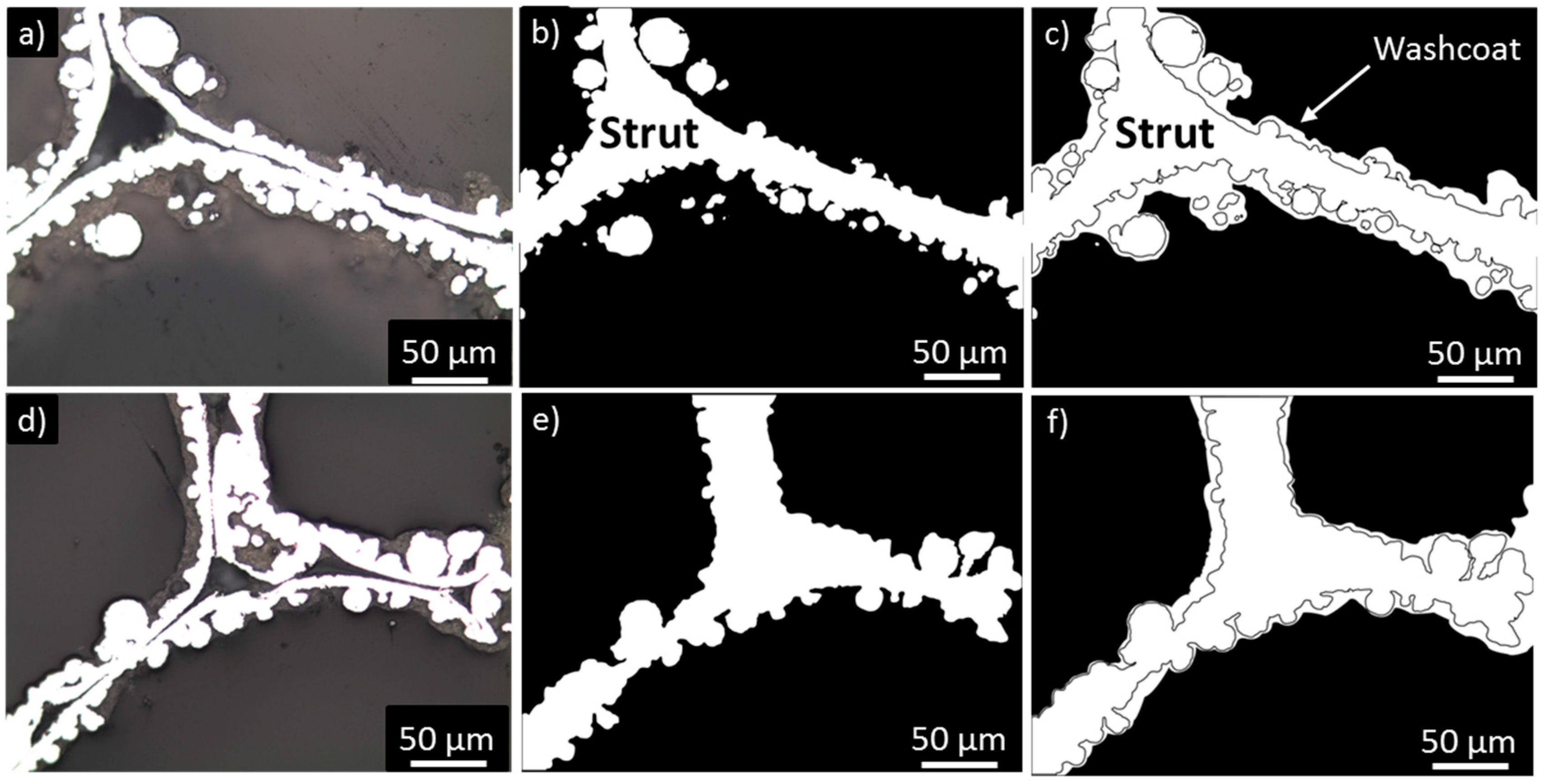
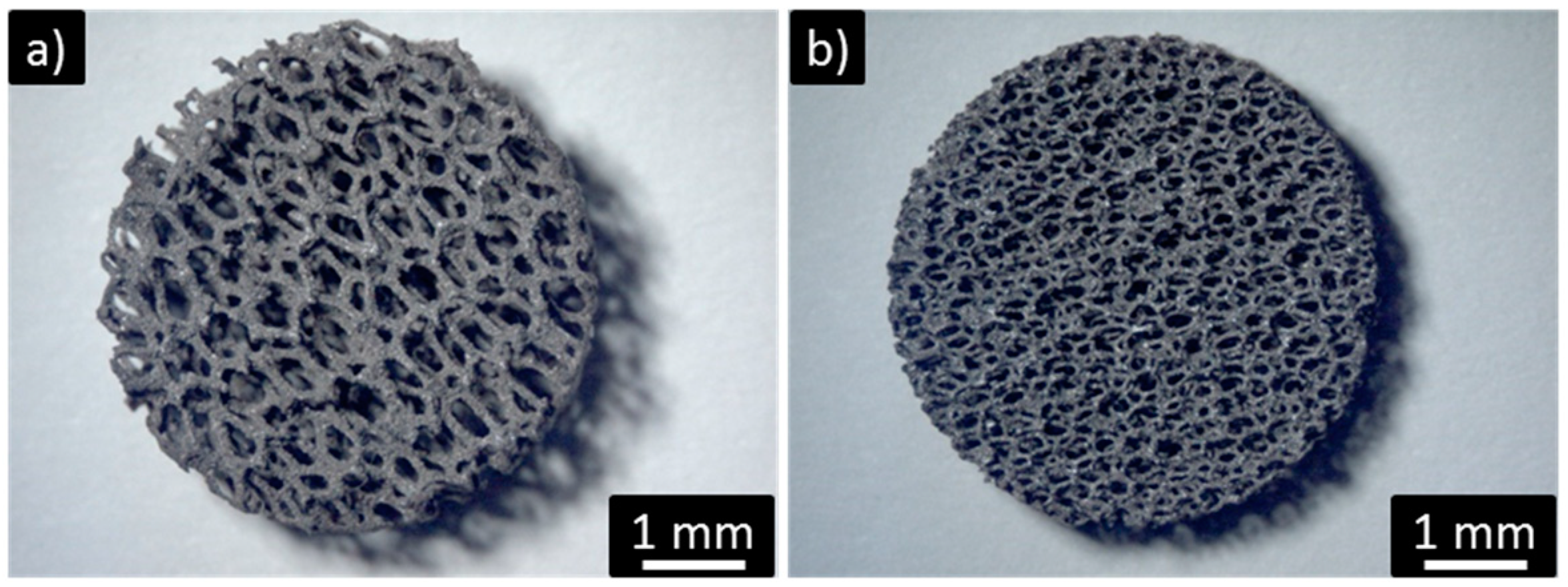
2.3. Washcoat Deposition

The PdCeHS slurry was deposited on the open cell metallic foams with 580 and 1200 µm cell diameters, following the procedure of Section 3.3. Figure 4 shows results obtained in terms of coating load, where the washcoat load after one deposition as function of the cell diameter is reported. Reported values are the average of measurements performed on three different samples for each deposition technique–cell diameter combination.
A remarkable standard deviation was found for dip-coated samples (Figure 4, see error bars), while spin-coated ones provided a good reproducibility. A possible explanation is that the lower washcoat load values obtained for spin-coated samples were due to the higher shear stresses induced by high speed rotation. This determines a more efficient removal of excess slurry and, thus, thin and homogeneous layers were obtained. As a consequence, the pore clogging phenomenon was prevented for spin-coated samples.
Optical microscope characterization of S1200 and S580 samples is reported in Figure 5, together with the results of the adhesion test.
All pictures were acquired with a 20× magnification by optical microscope. In all cases, the best results were obtained by using spin coating, which allows for high homogeneity of the washcoat and prevents (or limits) the occurrence of pore clogging. This was evident by comparing spin-coated (Figure 5a) and dip-coated (Figure 5b) S1200 samples, and it was even more evident for S580 samples (Figure 5d,e). The application of strong shear stresses during spinning induced a better control in wet coating formation, which was directly reflected in better results of washcoated layers. Despite the improvement in washcoat management, local clogging was still present in spin-coated S580 samples (Figure 5d), even though remarkably less than dip-coated ones (Figure 5e). Powder entrapped in pores was more brittle than washcoat layers deposited onto the support surface and, thus, it underwent detachment easily. For this reason, only weight loss results of S1200 (Figure 5c) can be considered as representative of washcoat–substrate interaction. In this case, losses in the 20% wt. with respect to deposited washcoat were found. Those losses are not negligible, but still acceptable considering the strong intensity of the vibration induced by adhesion tests. The strong increase in washcoat losses for S580 samples, reported in (Figure 5f), can therefore be associated to pore clogging.
In order to better analyze washcoat properties, the thickness of deposited catalytic layers was also assessed by fracture analysis according to the procedures in Section 3.3. Results are reported in Figure 6.
The cross section analysis also allowed for the evaluation of the metallic support surface morphology. This parameter can play a role in determining the adhesion of the washcoat layer. Irregular surfaces were found for both S1200 and S580 samples (Figure 6). Metal surface roughness was manifested by the presence of circular-shaped metal particles, which were randomly distributed onto the flat and concave metal surface. The presence of such an irregular surface of course had evident consequences on the washcoating process, as the slurry could easily fill superficial cavities. As a consequence, thicker layers were manifest in concave regions, while thinner layers were measured in those areas of higher convexity. As a macroscopic effect, the washcoating process resulted in a reduction of the irregularity of strut cross section. This was particularly evident in spin-coated samples of both 1200 µm (Figure 6c) and 580 µm (Figure 6d) cell diameters. Nevertheless, some local defects were still present in dip-coated samples (Figure 6a), due to the non-optimal liquid phase removal induced by film slip during withdrawing process.
On these bases, only an average thickness of the washcoat layer can be assumed, as the thickness locally could vary in a significant way, depending on surface roughness. Despite the random and complex foam surface geometry, in all cases the presence of a continuous washcoat layer was evident for our samples. Coated layers appeared to be well-adhered to the metal surface, and no defects or dis-homogeneities were detected at the washcoat/foam interface.
In order to support the previous discussion, image processing was performed on cross section pictures of 1200 µm and 580 µm cell diameter foams, coated by spin coating. Results are shown in Figure 7.
Figure 7a reports an as-acquired image for spin-coated S1200 samples. Image treatment of the as-acquired picture allowed discrimination of the contribution of support and washcoat layers. Indeed, the contribution of both parts is clear when comparing Figure 7b, where the high irregularity of metallic support strut shape is highlighted, with Figure 7c, where the washcoat layer is also manifest. The presence of the washcoat layer filled metallic structure voids, thus forming a homogeneous coverage of the structure without significantly modifying the average coated strut diameter. Similar considerations can be applied to the S580 sample (Figure 7d,f).
As a general consideration, it is worth mentioning that the spin coating process could be further improved by properly tuning operation parameters (i.e., rotation speed and time) or slurry properties (i.e., viscosity and powder concentration) to achieve both the targets of excess slurry removal and washcoat management.

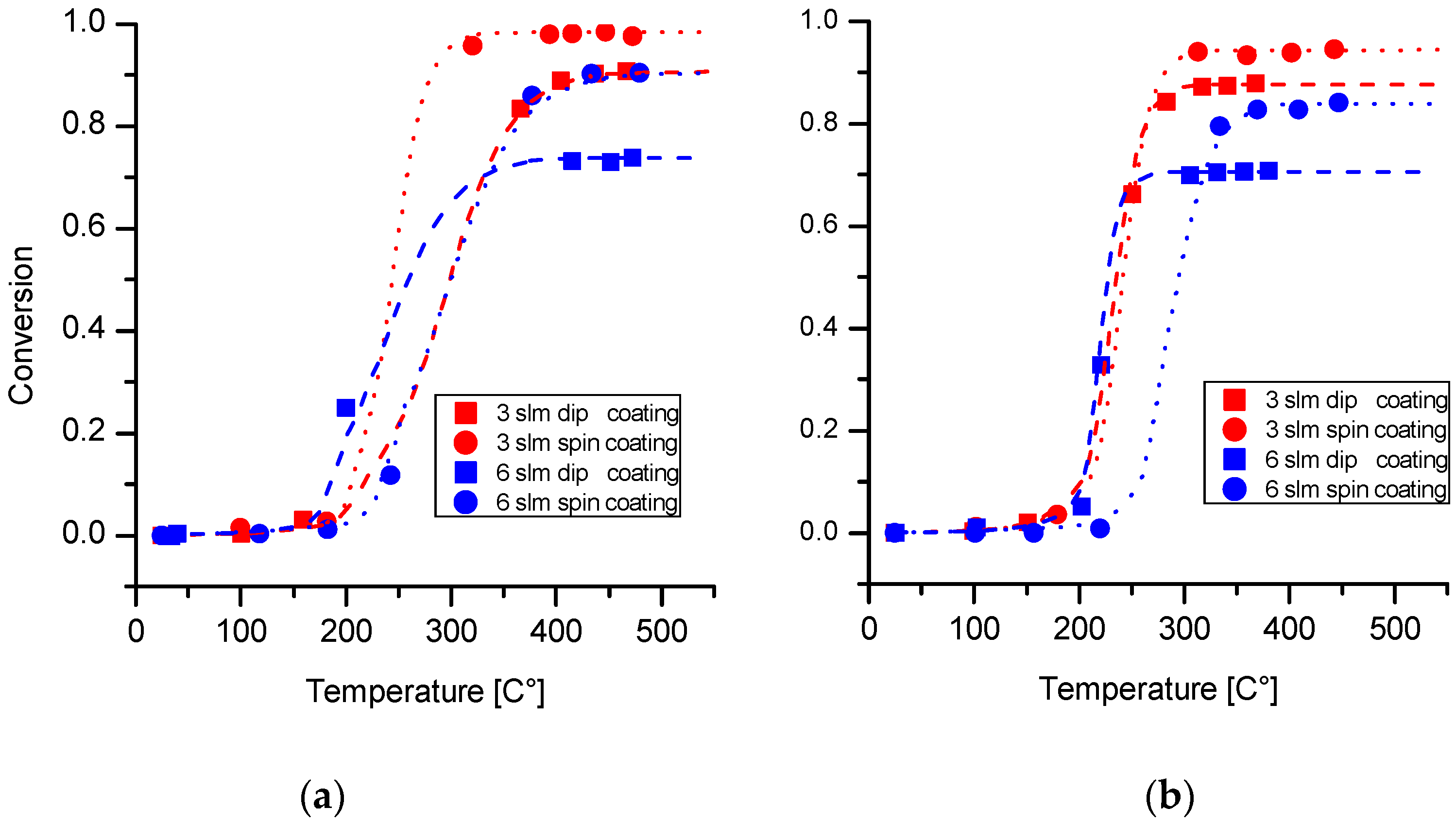
2.4. Catalytic Activity Test

Coated samples were tested in tubular micro-reactor to evaluate the catalytic performances of the CO oxidation reaction. As is well-documented in literature, CO oxidation is catalyzed even at low temperature by noble metals. This reaction is extremely simple, since it involves few species. Thus, for these reasons it has been considered for the evaluation of mass transfer performances. Figure 8 shows ignition curves for 580 and 1200 µm foams activated with spin coating and dip coating at 3 and 6 lit∙min−1. In the following, the two operative conditions will be labelled as 3 slm and 6 slm, respectively. In all the investigated flow rates, samples reached almost constant conversion as a function of temperature, excluding the presence of kinetic or internal transport limitations. In both cases, remarkably high conversions were achieved despite high flow rates, showing the potential of these supports in the design of compact reactors. For both 580 and 1200 µm foams, samples prepared with spin coating presented higher conversions in the diffusion-limited regime with respect to samples activated via dip coating in all the flow rates. This difference in the conversion can be explained by a higher coated area involved in the reaction despite a lower loading of catalyst powder. Spin coating is a more efficient coating strategy because it permits larger portions of foams to be coated with a lower amount of active phase, and it avoids preferential coating accumulation in some locations of the foam sample.
Samples prepared with spin coating also showed better performances in terms of durability, likely due to a more uniform coating thickness (as already documented in Section 2.2), combined with a lower amount of defects, like the whiskers highlighted in Figure 6.

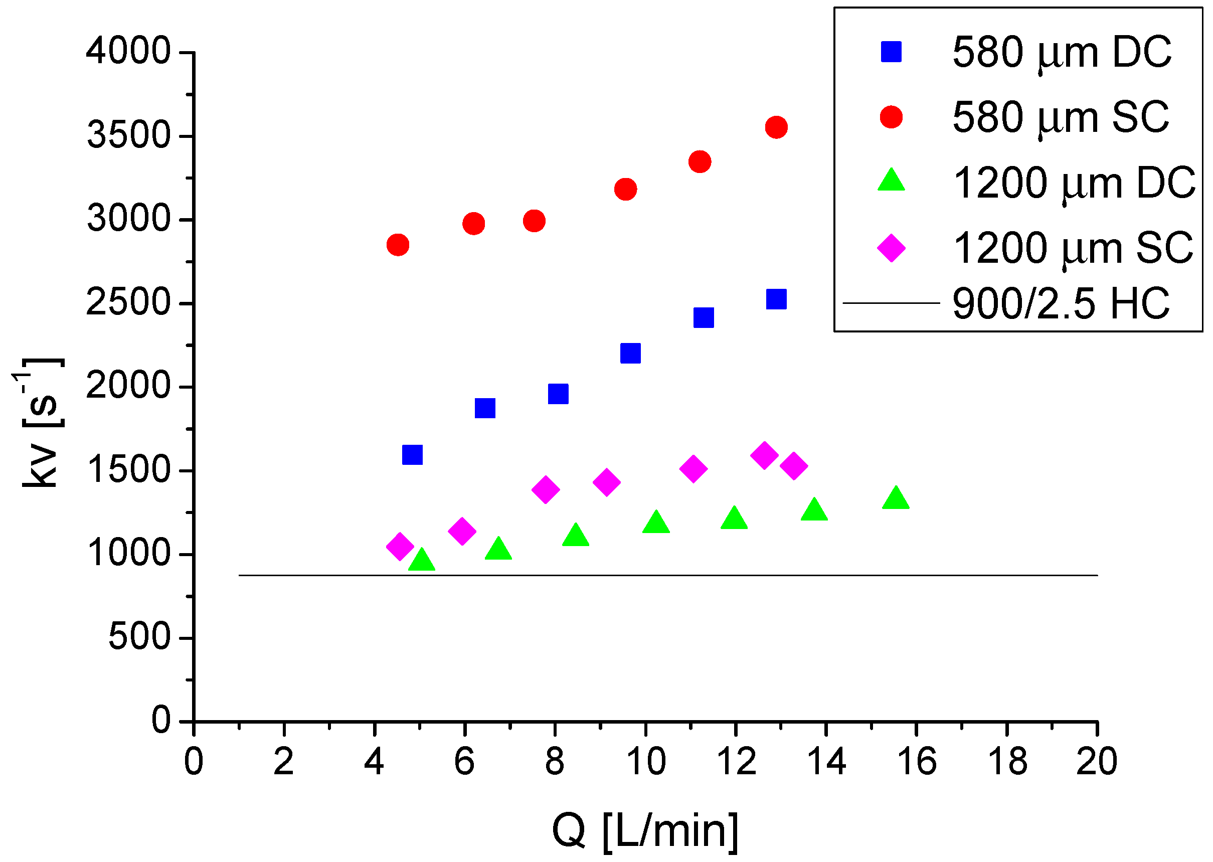
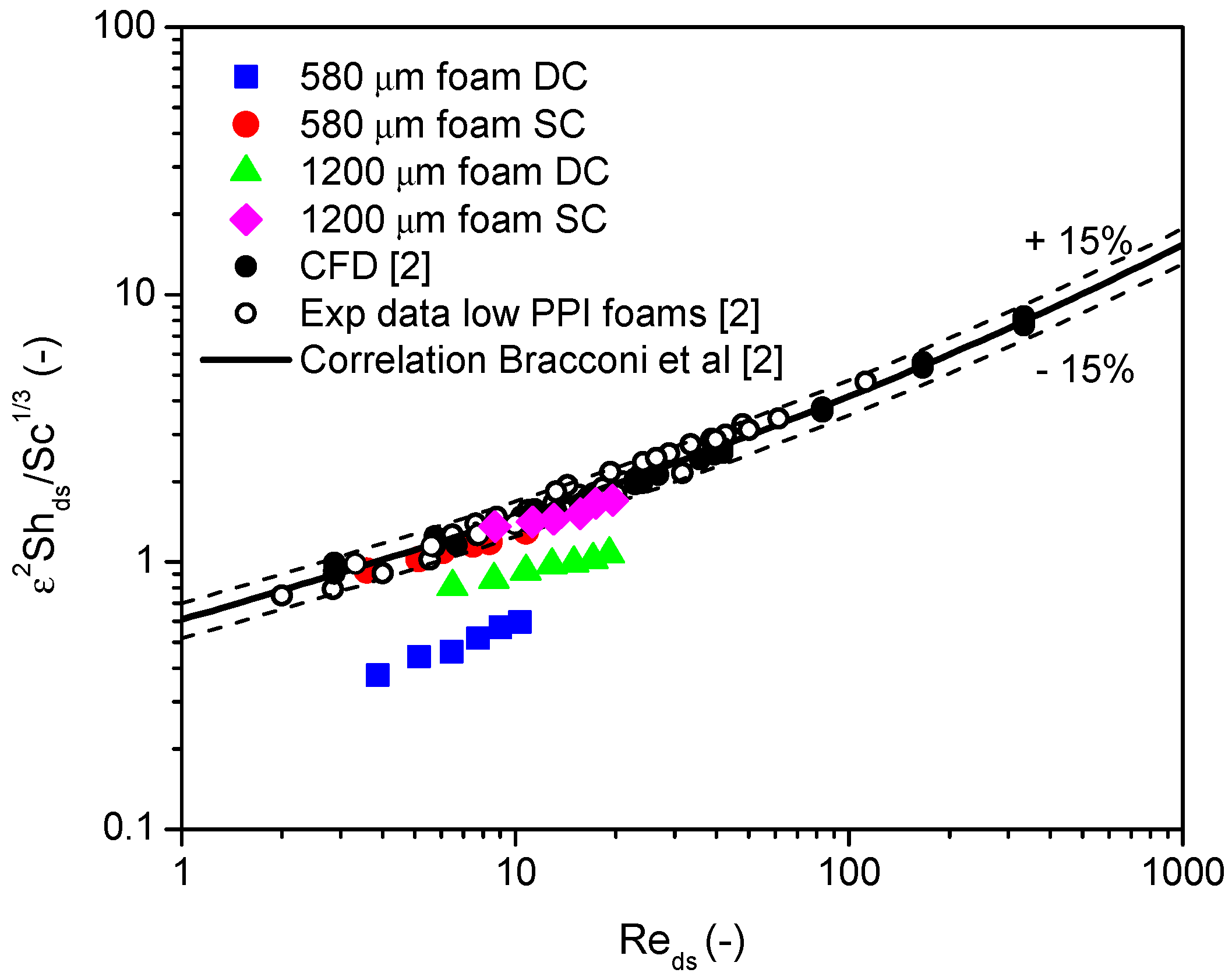
2.5. Analysis of Mass Transfer Performances

From the conversions measured in the diffusional regime, the first volumetric mass transfer coefficients were calculated to provide an easy comparison with square-channel honeycombs. Then, mass transfer performances were evaluated using the dimensionless Sherwood number and compared with the correlation derived by our group combining experimental, CFD—Computational Fluid Dynamics, and literature data [2].
The data collected on 580 µm foam prepared with spin coating were used for the derivation of the correlation. The volumetric mass transfer coefficient kv can be calculated as follows:
k v = ln ( 1 η ) Q V c a t = ln ( 1 η ) τ
where η is the CO conversion in the diffusion-limited regime, Q is the actualized volumetric flow rate evaluated at the average temperature between inlet and outlet, and V is the volume of the catalytic sample. The ratio between the actualized flow rate and the catalyst volume is the residence time τ.
kv (volumetric mass transfer coefficients) of the investigated samples are plotted against the actualized flow rate in Figure 9.
In the entire span of tested flow rates, all the tested foams overcame the performances of a reference 900/2.5 square-channel honeycomb calculated at 1.4 bar and 350 °C, a temperature where the foams were assumed to be in the diffusion-limited regime considering only asymptotic contribution [35]. As already reported in [2], the mass transfer coefficients of foams increased with increasing flow rate, while the asymptotic value for honeycombs was independent of the latter. Foams with 580 µm cells exhibited higher volumetric mass transfer coefficients than 1200 µm foams at the same flow rates, due to their higher exposed surface. As for the conversion, the volumetric mass transfer coefficients of foams prepared with spin coating were higher than the ones measured for foams prepared via dip coating, but the slope of the curves remained similar. This is clear evidence of a partial coating of the surface that led to lower conversion, and hence to lower mass transfer coefficients.
The usual methodology to analyze the mass transfer performances of structured catalyst is the dimensionless form
S h = k m L c D             k v = k m S v .
Sh is the Sherwood number, km is the mass transfer coefficient, Lc is the characteristic length, which accordingly to Bracconi et al. [2] is the average strut diameter, D is the diffusion coefficient of CO in the gas phase, kv is the volumetric mass transfer coefficient, and Sv is the surface-to-volume ratio of the foams evaluated with the model of Ambrosetti et al. [1].
The geometrical properties of the tested foams after washcoat deposition are reported in Table 2. A detailed description of the procedure used for the determination of these geometrical properties is reported in Section 3.3, based on a previous work by Bracconi et al. [2]. The specific surface area was calculated from the corrected cell diameter and the porosity after the deposition process calculated from the weight loading.
Figure 10 shows that the data collected on high-PPI foams prepared with spin coating were well aligned with CFD data and other experimental data collected on low-PPI foams.
The data on samples prepared with dip coating were instead systematically lower (especially the 580 μm foam) than the estimates of the correlation. Such deviations can be explained by a partial coating of the whole surface, as discussed above.

3. Materials and Methods

3.1. Catalyst Preparation

The catalytic materials were prepared by means of a precipitation-dry-impregnation method. The carrier was first produced by precipitation, and then it was made catalytically active by dry impregnation, with a solution containing active phase precursor. In a typical experiment, ceria precursor (Ce(NO3)3∙6H2O provided by Sigma-Aldrich St. Louis, MO, USA) was dissolved in distilled water until a 1 M concentration was reached. Then, the precipitating agent ((NH4)2CO3, Sigma-Aldrich, St. Louis, MO, USA) was added at room temperature in the form of a 2.6 M water solution, under magnetic stirring. The resulting slurry was filtered, washed, and dried overnight at 120 °C in a sealed oven. Then, the powder was calcined at 500 °C for 3 h (2 °C∙min−1 for both heating and cooling rates). Thus, high surface area cerium oxide (CeHS) was obtained [12].
A dry impregnation (or incipient wetness) technique was applied to activate the cerium-based support [4]. As precursor of the active phase, Pd(NO3)2 water solution (12–16% w/w by Alfa Aesar Haverhill, MA, USA) was used. The total amount of solution was calculated according to the specific pore volume of the carrier, while Pd content was fixed at 3% wt. of metal with respect to metal and carrier total mass. The impregnated powder was dried overnight at 120 °C, and then it was calcined at 500 °C for 10 h (heating and cooling rate set at 2 °C∙min−1). From thermogravimetric analysis, calcination at 500 °C was demonstrated to be suitable for both slurry organic components decomposition and palladium nitrate oxidation to PdO. In the following, this powder will be identified as PdCeHS.

3.2. Catalyst Characterization

Powders were characterized by means of X-ray diffraction measurements (XRD). A Bruker D8 Advance diffractometer (Billerica, MA, USA) using graphite monochromated Cu-Kα radiation was used. Diffractogram acquisitions were performed in the 2θ range 10–80°. Scan steps were set to 0.02° 2θ, while measurement time was 1 s per step [36]. Additionally, powders were characterized by means of FT-IR analysis (FT-IR 615 by Jasco Easton, MD, USA).
Metal active phase content was quantified by means of SEM-EDS measurements coupled with a micro analysis system for imaging the spatial variation of elements in a sample. An EVO 50 Series instrument (ZEISS, Oberkochen, Germany) equipped with an INCAEnergy 350 EDS and an INCASmartMap detector was used.
Thermogravimetric analyses were performed with two heating–cooling cycles between room temperature and 1000 °C in air (5 °C∙min−1 for both heating and cooling phases using an Extar 6000 instrument by Seiko Instrument, Chiba, Japan). Tests were run referring to a procedure reported in Reference [31].
BET surface area and pore volume were determined by means of a Micromeritics Tristar 3000 instruments (Micromeritics, Norcross, GA, USA) using both N2 adsorption and Hg intrusion techniques.

3.3. Open Cell Foams Characterization

Foam cell size was evaluated by means of optical microscope analysis (DMLM by Leica Microsystems Wetzlar, Germany equipped with Leica application suite for digital acquisition). In a typical experiment, several pictures were captured and different elements were repeatedly measured to get an average value (i.e., cell size, pore size, and strut diameter). From the point of view of void fraction, an ethanol balance was used for the measurements. Samples were measured both in air and in ethanol. Then, void fraction was determined according to
Hydraulic   porosity   ( ε ) = 1 Foam   density   Hydraulic   solid   density ,
where foam density is measured as the ratio between foam mass, measured in air, and foam volume, while the hydraulic solid density is determined according to
Hydraulic   solid   density = 1 m A i r · ρ E t O H   ( m A i r m E t O H ) ,
where mAir is foam mass is air, ρEtOH is ethanol density, and mEtOH is foam mass measured in ethanol. Additionally, both void fraction and cell diameter were corrected taking into account the presence of the washcoat layer. A description of the methodology can be found in [2].

3.4. Washcoating

PdCeHS catalytic powder was deposited on FeCrAl alloy open cell foams provided by Alantum GMBH (Novi, MI, USA). In this work, deposition over two different open cell foams, namely with a cell diameter of 580 and 1200 µm, were investigated (Figure 11). Supports were provided in the form of cylinders with 9 mm diameter. Support height was equal to 1.9 and 3.1 mm for samples with pore diameters of 580 and 1200 µm, respectively.
Before coating deposition, metallic supports were cleaned for 30 min in an ultrasonic bath using acetone. In view of pursing washcoat adhesion, samples were calcined at 900 °C for 10 h (2 °C∙min−1 for both heating and cooling steps) in order to promote alumina formation on metallic surface [14].
The production of powder slurries was based on a procedure reported in Reference [8]. Liquid medium (HGP in the following), composed of glycerol (G, dispersant), distilled water (H, solvent/diluent), and polyvinyl alcohol (PVA, binder) was used. Component-to-powder ratios were fixed to 1.9 (G), 1.8 (H), and 0.07 (PVA), respectively.
Briefly, PVA was dissolved in water at 85 °C under continuous magnetic stirring. The solution, cooled down to room temperature and continuously stirred, was then added with glycerol. Pd-supported cerium-based powders were mixed with the HGP liquid medium and ball milled for 24 h at 50 rpm using zirconium oxide milling bodies. After the milling process, ethanol (0.39 g/g powder) was added to the formulation to reduce foaming.
Slurry was characterized in terms of rheological properties by using a dynamic stress device by Rheometrics (New Castle, DE, USA). A parallel disc configuration was used (disc diameter of 40 mm), and viscosity measurements were run in the 1–103 s−1 shear rate range, at 25 °C.
Two different coating techniques were used to deposit catalysts on the support surface, namely dip coating and spin coating. In case of dip coating, both dipping and withdrawing speeds were set at 13 cm∙min−1. Excess coating was gently removed by air blowing. On the contrary, spin-coated samples were freely dipped into the slurry and withdrawn. Then, excess slurry removal was performed by spin coating operation by using a self-assembled device. Rotation speed was set at 2000 rpm, while rotation time was set at 15 s.
The wet coating layer was consolidated by a flash drying step that included a thermal treatment at 350 °C for 6 min in a preheated oven [11]. Finally, samples were calcined at 500 °C for 10 h, with 2 °C∙min−1 heating and cooling ramps [4].
According to the literature, washcoat load and adhesion were measured using gravimetric analysis and sonication in petroleum ether, respectively [7]. An optical microscope (SZ-CTV by Olympus Tokio, Japan) was used to characterize coating layers’ homogeneity and morphology.
Fracture analysis was used to evaluate washcoat thickness. Samples were included in epoxy resin (Mecaprex by Presi, Eybens, France) in order to prevent deposited layers’ detachment. After resin solidification, samples were cut along the radial direction and, after surface polishing, internal faces were accessible. Washcoat layers’ morphology and thickness were thus characterized by optical microscope (DMLM by Leica Microsystems, Wetzlar, Germany) and digital acquisition software (Leica application suite by Leica Microsystems, Wetzlar, Germany).

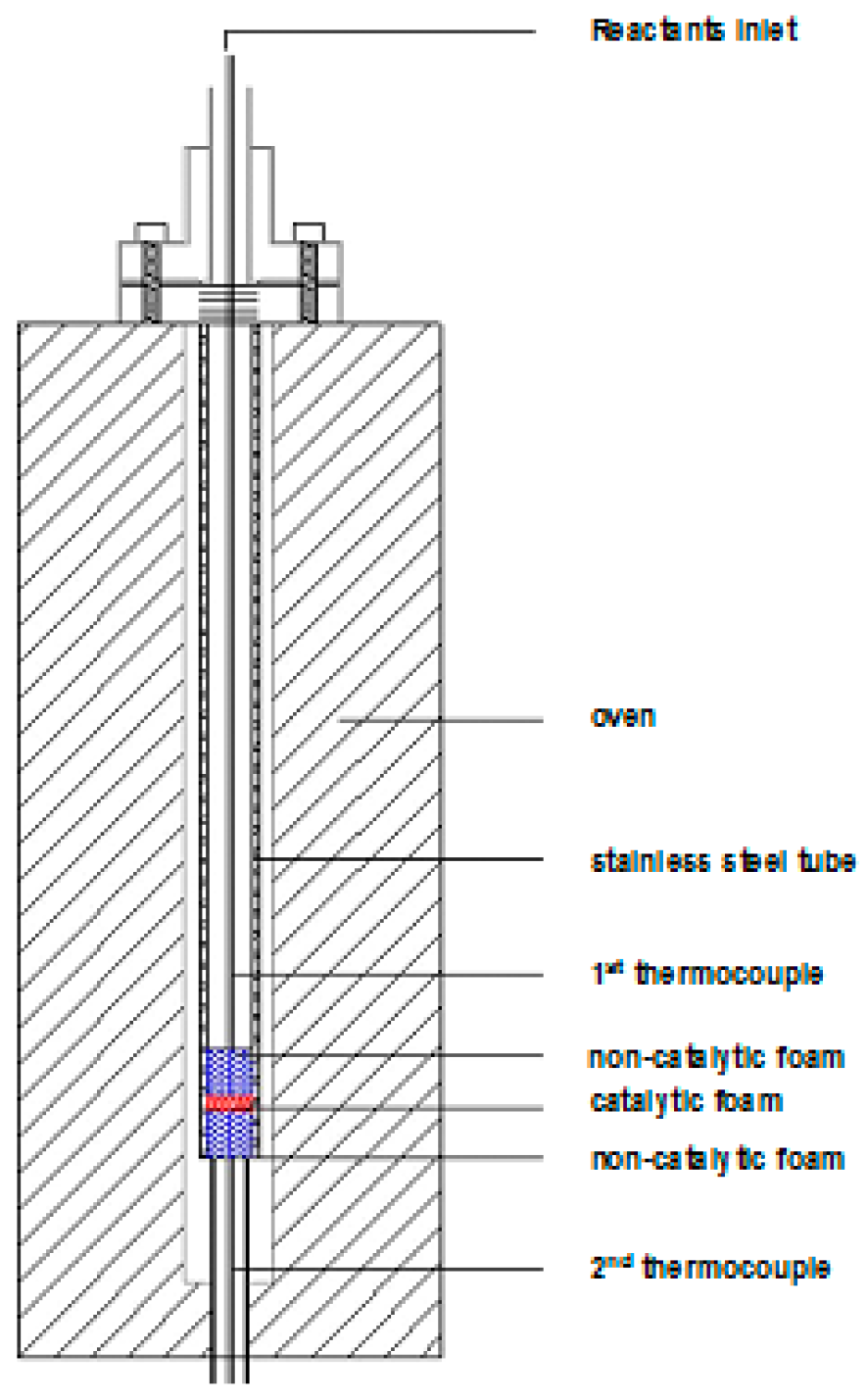
3.5. Catalyst Testing

The activity of the washcoated samples was tested running CO catalytic combustion in air in a 9 mm tubular lab-scale reactor, placed into an oven as represented in Figure 12. Carbon monoxide and air were supplied through gas lines. Flow rates were adjusted with Brooks mass flow controllers (Brooks Instruments, Hatfield, PA, USA). Gases were mixed and preheated in a coil up to 125 °C. Different flow rates were tested in the range 1–9 lit∙min−1 at STP (25 °C and 1 bar). To observe the effect of the concentration on the conversions and the ignition point, the inlet CO concentration was varied from 1% to 3% (v/v) in air. The compositions of reactants and products were analyzed with a gas chromatograph 6890N from Agilent Technologies (Santa Clara, CA, USA) equipped with two thermal conductivity detectors (TCDs) and two packed columns, one filled with Molecular Sieve 5A 80/100 mesh suitable to analyze O2, N2, and CO, the other column filled with Porapak Q 80/100 to separate CO2.
In order to avoid flow maldistributions and inlet effects, additional bare foams were added upstream and downstream of the active sample. In particular, for 1200 μm foams, two bare samples with the same geometry were stacked at the inlet and at the outlet, while for the 580 μm foam the inlet bed was composed of two 60 PPI foams and a single 100 PPI foam. Two temperature measures were collected, one in proximity of the inlet (Thermocouple 1 in Figure 12) and the second one in contact with the bottom of the uncoated foam (Thermocouple 2 in Figure 12). Due to the great amount of heat released during the reaction, the temperature increase along the bed was up to 90 °C. During an experimental campaign, at a given flow rate, tests at different inlet temperature were performed changing the oven temperature stepwise. In each condition, the conversion of CO was determined by carbon balance over gas chromatography analysis once stable temperatures were observed for each inlet temperature set. The overall absolute errors detected in carbon balances were in the range 1–3%.
Due to the exothermic character of the reaction, an increase of temperature was observed after the ignition. Only analyses almost in the diffusive control regime were performed, due to the problematic control of the temperature in the kinetically-limited region of the reaction. Before performing the catalytic tests, it was assessed that bare foams did not provide any significant conversions, since conversions lower than 3% were observed up to 450 °C.
The absence of bypass was checked by running tests at low flow rates (e.g., tests at 1 lit∙min−1). Complete conversion of CO was observed. This result enabled us to conclude that a correct flow distribution over the catalytic sample was present and that the catalyst was active enough for the purposes of the work.

4. Conclusions

Spin coating of high-PPI foams was evaluated as a possible alternative deposition technique to the commonly used dip coating process. The influences of the deposition technique on the final structured catalysts were evaluated from both the washcoat quality and catalytic performance points of view. The following main conclusions could be drawn:
  • Spin coating allows effective control of wet coating formation onto metallic open cell foams with cell diameters down to 500 μm. Thanks to the higher shear stresses induced by rotation during wet film deposition, this technique is able to produce better results in terms of reduced clogging phenomena and higher film homogeneity with respect to dip coating.
  • The use of the reported deposition methodologies allowed very thin catalytic layers to be obtained, without remarkably affecting the strut average thickness.
  • The deposition method has a strong effect on the catalytic performances of the samples: foams prepared with spin coating outperformed samples activated via dip coating.

Author Contributions

Conceptualization: M.A., R.B., C.C., G.G. and E.T.; Data curation, M.A. and R.B.; Funding acquisition, E.T.; Investigation, M.A. and R.B.; Project administration, C.C., G.G. and E.T.; Supervision, C.C., G.G. and E.T.; Writing–original draft, M.A., R.B., C.C., G.G. and E.T.

Funding

Authors acknowledge the European Research Council for funding provided within the project INTENT (“Structured Reactors with Intensified Energy Transfer for Breakthrough Catalytic Technologies”, Grant Agreement No. 694910).

Conflicts of Interest

The authors declare no conflict of interest.

References

  1. Ambrosetti, M.; Bracconi, M.; Groppi, G.; Tronconi, E. Analytical Geometrical Model of Open Cell Foams with Detailed Description of Strut-Node Intersection. Chem. Ing. Tech. 2017, 89, 915–925. [Google Scholar] [CrossRef]
  2. Bracconi, M.; Ambrosetti, M.; Maestri, M.; Groppi, G.; Tronconi, E. A fundamental investigation of gas/solid mass transfer in open-cell foams using a combined experimental and CFD approach. Chem. Eng. J. 2018, 352, 558–571. [Google Scholar] [CrossRef]
  3. Meille, V. Review on methods to deposit catalysts on structured surfaces. Appl. Catal. A Gen. 2006, 315, 1–17. [Google Scholar] [CrossRef]
  4. Montebelli, A.; Visconti, C.G.; Groppi, G.; Tronconi, E. Methods for the catalytic activation of metallic structured substrates. Catal. Sci. Technol. 2014, 4, 2846–2870. [Google Scholar] [CrossRef]
  5. Brinker, C.J.; Scherer, G.W. Sol-Gel Science: The Physics and Chemistry of Sol-Gel Processing; Academic Press: San Diego CA, USA, 1990; ISBN 9780080571034. [Google Scholar]
  6. Middleman, S. Fundamentals of Polymer Processing; McGraw-Hill Inc.: New York NY, USA, 1977; ISBN 978-0070418516. [Google Scholar]
  7. Cristiani, C.; Finocchio, E.; Latorrata, S.; Visconti, C.G.; Bianchi, E.; Tronconi, E.; Groppi, G.; Pollesel, P. Activation of metallic open-cell foams via washcoat deposition of Ni/MgAl2O4 catalysts for steam reforming reaction. Catal. Today 2012, 197, 256–264. [Google Scholar] [CrossRef]
  8. Valentini, M.; Groppi, G.; Cristiani, C.; Levi, M.; Tronconi, E.; Forzatti, P. The deposition of γ-Al2O3 layers on ceramic and metallic supports for the preparation of structured catalysts. Catal. Today 2001, 69, 307–314. [Google Scholar] [CrossRef]
  9. Montebelli, A.; Visconti, C.G.; Groppi, G.; Tronconi, E.; Kohler, S.; Johnsen, H.; Myrstad, R. Washcoating and chemical testing of a commercial Cu/ZnO/Al2O3 catalyst for the methanol synthesis over copper open-cell foams. Appl. Catal. A Gen. 2014, 481, 96–103. [Google Scholar] [CrossRef]
  10. Meille, V.; Pallier, S.; Santa Cruz Bustamante, G.V.; Marilyne Roumanie, J.-P.R.; Roumanie, M.; Reymond, J.-P. Deposition of gamma-Al2O3 layers on structured supports for the design of new catalytic reactors. Appl. Catal. A Gen. 2005, 286, 232–238. [Google Scholar] [CrossRef]
  11. Balzarotti, R.; Cristiani, C.; Latorrata, S.; Migliavacca, A. Washcoating of low surface area cerium oxide on complex geometry substrates. Part. Sci. Technol. 2016, 34, 184–193. [Google Scholar] [CrossRef]
  12. Balzarotti, R.; Italiano, C.; Pino, L.; Cristiani, C.; Vita, A. Ni/CeO2-thin ceramic layer depositions on ceramic monoliths for syngas production by oxy steam reforming of biogas. Fuel Process. Technol. 2016, 149, 40–48. [Google Scholar] [CrossRef]
  13. Italiano, C.; Balzarotti, R.; Vita, A.; Latorrata, S.; Fabiano, C.; Pino, L.; Cristiani, C. Preparation of structured catalysts with Ni and Ni-Rh/CeO2 catalytic layers for syngas production by biogas reforming processes. Catal. Today 2016, 273, 3–11. [Google Scholar] [CrossRef]
  14. Giani, L.; Cristiani, C.; Groppi, G.; Tronconi, E. Washcoating method for Pd/gamma-Al2O3 deposition on metallic foams. Appl. Catal. B Environ. 2006, 62, 121–131. [Google Scholar] [CrossRef]
  15. Boettge, D.; Standke, G.; Fuessel, A.; Adler, J. Functionalization of open-celled foams by homogeneous slurry based coatings. J. Mater. Res. 2013, 28, 2220–2233. [Google Scholar] [CrossRef]
  16. Sanz, O.; Almeida, L.C.; Zamaro, J.M.; Montes, M.; Miro, E.E. Washcoating of Pt-ZSM5 onto aluminium foams. Appl. Catal. B Environ. 2008, 78, 166–175. [Google Scholar] [CrossRef]
  17. Gokon, N.; Kodama, T.; Imaizumi, N.; Umeda, J.; Seo, T. Ferrite/zirconia-coated foam device prepared by spin coating for solar demonstration of thermochemical water-splitting. Int. J. Hydrogen Energy 2011, 36, 2014–2028. [Google Scholar] [CrossRef]
  18. Zhang, H.; Suszynski, W.J.; Agrawal, K.V.; Tsapatsis, M.; Al Hashimi, S.; Francis, L.F. Coating of open cell foams. Ind. Eng. Chem. Res. 2012, 51, 9250–9259. [Google Scholar] [CrossRef]
  19. Zhao, C.Y. Review on thermal transport in high porosity cellular metal foams with open cells. Int. J. Heat Mass Transf. 2012, 55, 3618–3632. [Google Scholar] [CrossRef]
  20. Zhou, W.; Ke, Y.; Wang, Q.; Wan, S.; Lin, J.; Zhang, J.; Hui, K.S. Development of cylindrical laminated methanol steam reforming microreactor with cascading metal foams as catalyst support. Fuel 2017, 191, 46–53. [Google Scholar] [CrossRef] [Green Version]
  21. Wang, C.; Ping, D.; Dong, X.; Dong, Y.; Zang, Y. Construction of Ru/Ni-Al-oxide/Ni-foam monolithic catalyst for deep-removing CO in hydrogen-rich gas via selective methanation. Fuel Process. Technol. 2016, 148, 367–371. [Google Scholar] [CrossRef]
  22. Yu, H.; Chen, H.; Pan, M.; Tang, Y.; Zeng, K.; Peng, F.; Wang, H. Effect of the metal foam materials on the performance of methanol steam micro-reformer for fuel cells. Appl. Catal. A Gen. 2007, 327, 106–113. [Google Scholar] [CrossRef]
  23. Yang, H.; Li, J.; Yu, H.; Peng, F.; Wang, H. Metal-foam-supported Pd/Al2O3 catalysts for catalytic combustion of methane: Effect of interaction between support and catalyst. Int. J. Chem. React. Eng. 2015, 13, 83–93. [Google Scholar] [CrossRef]
  24. Ho, P.H.; Ambrosetti, M.; Groppi, G.; Tronconi, E.; Jaroszewicz, J.; Ospitali, F.; Rodriguez-Castellon, E.; Fornasari, G.; Vaccari, A.; Benito, P. One-step electrodeposition of Pd-CeO2 on high pore density foams for environmental catalytic processes. Catal. Sci. Technol. 2018, 8, 4678–4689. [Google Scholar] [CrossRef]
  25. Ho, P.; Scavetta, E.; Tonelli, D.; Fornasari, G.; Vaccari, A.; Benito, P. Hydrotalcite-type materials electrodeposited on open-cell metallic foams as structured catalysts. Inorganics 2018, 6, 74. [Google Scholar] [CrossRef]
  26. Zhang, Q.; Wu, X.; Li, Y.; Chai, R.; Zhao, G.; Wang, C.; Gong, X.; Liu, Y.; Lu, Y. High-Performance PdNi Nanoalloy Catalyst in Situ Structured on Ni Foam for Catalytic Deoxygenation of Coalbed Methane: Experimental and DFT Studies. ACS Catal. 2016, 6, 6236–6245. [Google Scholar] [CrossRef]
  27. Zhang, Q.; Li, Y.; Chai, R.; Zhao, G.; Liu, Y.; Lu, Y. Low-temperature active oscillation-free PdNi (alloy)/Ni-foam catalyst with enhanced heat transfer for coal bed methane deoxygenation via catalytic combustion. Appl. Catal. B Environ. 2016, 187, 238–248. [Google Scholar] [CrossRef]
  28. Li, Y.; Zhang, Q.; Chai, R.; Zhao, G.; Cao, F.; Liu, Y.; Lu, Y. Metal-foam-structured Ni-Al2O3 catalysts: Wet chemical etching preparation and syngas methanation performance. Appl. Catal. A Gen. 2016, 510, 216–226. [Google Scholar] [CrossRef]
  29. Chai, R.; Li, Y.; Zhang, Q.; Zhao, G.; Liu, Y.; Lu, Y. Monolithic Ni-MOx/Ni-foam (M = Al, Zr or Y) catalysts with enhanced heat/mass transfer for energy-efficient catalytic oxy-methane reforming. Catal. Commun. 2015, 70, 1–5. [Google Scholar] [CrossRef]
  30. Roberts, M.; Huang, A.F.; Johns, P.; Owen, J. Dip-spin coating of reticulated vitreous carbon with composite materials to act as an electrode for 3D microstructured lithium ion batteries. J. Power Sources 2013, 224, 250–259. [Google Scholar] [CrossRef]
  31. Groppi, G.; Cristiani, C.; Lietti, L.; Ramella, C.; Valentini, M.; Forzatti, P. Effect of ceria on palladium supported catalysts for high temperature combustion of CH4 under lean conditions. Catal. Today 1999, 50, 399–412. [Google Scholar] [CrossRef]
  32. Balzarotti, R.; Ciurlia, M.; Cristiani, C.; Paparella, F. Washcoat deposition of Ni- and Co-ZrO2 low surface area powders onto ceramic open-cell foams: Influence of slurry formulation and rheology. Catalysts 2015, 5, 2271–2286. [Google Scholar] [CrossRef] [Green Version]
  33. Olhero, S.M.; Ferreira, J.M.F. Influence of particle size distribution on rheology and particle packing of silica-based suspensions. Powder Technol. 2004, 139, 69–75. [Google Scholar] [CrossRef]
  34. Zupancic, A.; Kristo, A. Influence of particle concentration on rheological properties of aqueous Al2O3 suspensions. J. Eur. Ceram. Soc. 1998, 18, 467–477. [Google Scholar] [CrossRef]
  35. Tronconi, E.; Forzatti, P. Adequacy of lumped parameter models for SCR reactors with monolith structure. AIChE J. 1992, 38, 201–210. [Google Scholar] [CrossRef]
  36. Cullity, B.D. Elements of X-ray Diffraction, 3rd ed.; Pearson: Upper Saddle River, NJ, USA, 2001; ISBN 978-0201610918. [Google Scholar]
Figure 1. XRD analysis Pd-CeO2 catalyst powder. The detail reports a magnification of CeHS and PdCeHS diffractograms in the 25.5–34.5° 2θ region.
Catalysts 08 00510 g001
Figure 2. Fourier transform infrared (FT-IR) spectra of PdCeHS before and after thermal treatment compared with bare CeHS support.
Catalysts 08 00510 g002
Figure 3. Flow curves of CeHS and PdCeHS slurries.
Catalysts 08 00510 g003
Figure 4. Average washcoat load after one deposition as a function of support cell diameter.
Catalysts 08 00510 g004
Figure 5. Optical microscope analysis of spin-coated (a,d) and dip-coated (b,e) foams of 1200 µm (a,b) and 580 µm (d,e) cell diameters. Losses after adhesion tests are reported in (c,f) for S1200 and S580 samples, respectively.
Catalysts 08 00510 g005
Figure 6. Optical microscope analysis of deposited catalytic layers: S1200 (a,c) and S580 (b,d) samples. Deposition were made by dip coating (a,b) and spin coating (c,d).
Catalysts 08 00510 g006
Figure 7. Image processing on cross section images of spin-coated S1200 (ac) and S580 (df) foams.
Catalysts 08 00510 g007
Figure 8. Conversions at 3 and 6 lit∙min−1 for foams prepared with spin coating and dip coating: (a) 580 µm foam; (b) 1200 µm foam.
Catalysts 08 00510 g008
Figure 9. Volumetric mass transfer coefficients for the prepared samples as a function of actualized flow rates: DC—dip coated samples, SC—spin coated samples, HC square channel honeycomb.
Catalysts 08 00510 g009
Figure 10. Comparison of mass transfer coefficients of foams prepared with spin coating and dip coating with the data presented in [2].
Catalysts 08 00510 g010
Figure 11. Open cell FeCrAl foams of different cell diameters: 1200 µm (a) and 580 µm (b).
Catalysts 08 00510 g011
Figure 12. View of the test tubular reactor.
Catalysts 08 00510 g012
Table 1. Active phase content of PdCeHS samples.
Nominal Content (% wt.)TG (% wt.)SEM-EDS (% wt.)
32.92.5 ± 0.3
Table 2. Geometrical properties of tested samples, evaluated before (in brackets) and after coating deposition.
SampleLoad (% wt.%)Dcell (mm)ε (-)Sv (m−1)Lc (mm)
580 µm DC24.20.551 (0.643)0.813 (0.915)6523 (4185)0.141(0.099)
580 µm SC7.90.625 (0.643)0.880 (0.915)4973 (4185)0.117 (0.099)
1200 µm DC23.41.131 (1.278)0.881 (0.9345)2906 (1860)0.236 (0.157)
1200 µm SC17.21.171 (1.278)0.892 (0.9345)2627 (1860)0.217 (0.157)

