Article

Gaseous Nitric Acid Activated Graphite Felts as Hierarchical Metal-Free Catalyst for Selective Oxidation of H2S

1
Institute of Chemistry and Processes for Energy, Environment and Health (ICPEES), ECPM, UMR 7515 CNRS-University of Strasbourg, 25 rue Becquerel, 67087 Strasbourg CEDEX 02, France
2
Ha Noi University of Mining and Geology, 18 Pho Vien, Duc Thang, Bac Tu Liem, Ha Noi, Viet-Nam
3
The University of Da-Nang, University of Science and Technology, 54 Nguyen Luong Bang, Da-Nang, Viet-Nam
*
Authors to whom correspondence should be addressed.
Catalysts 2018, 8(4), 145; https://doi.org/10.3390/catal8040145
Submission received: 5 March 2018 / Revised: 29 March 2018 / Accepted: 30 March 2018 / Published: 4 April 2018

Abstract

:
In this study, we reported on the influence of gaseous HNO3 treatment on the formation of defects decorated with oxygenated functional groups on commercial graphite felts (GFs). The gaseous acid treatment also leads to a remarkable increase of the specific as well as effective surface area through the formation of a highly porous graphite structure from dense graphite filamentous. The as-synthesized catalyst was further used as a metal-free catalyst in the selective oxidation of H2S in industrial waste effluents. According to the results, the defects decorated with oxygenated groups were highly active for performing selective oxidation of H2S into elemental sulfur. The desulfurization activity was relatively high and extremely stable as a function of time on stream which indicated the high efficiency of these oxidized un-doped GFs as metal-free catalysts for the selective oxidation process. The high catalytic performance was attributed to both the presence of structural defects on the filamentous carbon wall, which acting as a dissociative adsorption center for the oxygen, and the oxygenated functional groups, which could play the role of active sites for the selective oxidation process.

Graphical Abstract

1. Introduction

Nanocarbon-based metal-free catalysts consisting of a nitrogen-doped carbon matrix have received an ever increasing scientific and industrial interest in the field of heterogeneous catalysis over the last decade for several potential processes [1,2,3,4,5,6]. The introduction of hetero-element atoms, i.e., N, S, or P, inside the carbon matrix leads to the formation of metal-free catalysts which can activate oxygen bonding to generate reactive intermediates in different catalytic reactions according to the first report from Dai and co-workers [7]. The most studied form of these metal-free catalysts consisted of carbon nanotubes doped with nitrogen atoms, which has been extensively used in several catalytic processes [8,9,10,11,12,13]. Recently, work reported by Pham-Huu and Gambastiani [14,15] has shown that nitrogen-doped mesoporous carbon film, synthesized from food stuff raw materials, displays a high performance for different catalytic processes such as oxygen reduction reaction (ORR), direct dehydrogenation of ethylbenzene and selective oxidation of H2S. Such nitrogen-doped metal-free catalysts display an extremely high stability as a function of time on stream or cycling tests which could be directly attributed to the complete lack of sintering consecutively to the direct incorporation of the nitrogen atoms inside the carbon matrix.
Nitrogen sites could also be efficiently replaced by carbon nanotubes containing surface defects decorated with oxygenated functional groups for the selective oxidation of H2S into elemental sulfur [16]. Such a carbon metal-free catalyst displays a high stability as a function of the test duration under severe reaction conditions, i.e., high space velocity, low O2-to-H2S ratio. In the literature, the incorporation of these oxygenated functional groups has generally been carried out through oxidation treatments of the pristine carbon materials with different oxidants such as liquid HNO3 [17,18], H2SO4 [19], KMnO4 [20], and H2O2 [21] or through gaseous reactants like oxygen plasma [22], ozone [23], or CO2 [24]. The main drawbacks of the liquid-phase treatments are the generation of a large amount of acid waste and the need for a subsequent washing step to remove the residual acid adsorbed on the sample surface. The gas-phase treatments seem to be the most appropriate ones for generating oxygenated functional groups on the carbon-based surface. Recent work by Su and co-workers [25] has shown that catalyst consisting of carbon nanotubes treated under ozone displays a high catalytic performance for different catalytic processes. The main drawback of such nano-catalyst is its nanoscopic dimension which renders difficult handling and transport and induces a high pressure drop in an industrial fixed-bed configuration. The catalyst recovery also represents a problem of health concerns due to its high ability to be breathed. In addition, the carbon nanotubes synthesis also requires the use of explosive and toxic organic compounds and hydrogen which induce a high cost operation due to the post-synthesis treatment of the by-products [26,27]. The purification process to remove the growth catalyst also leads to the generation of a large amount of wastewater, consecutive to the acid and basic treatment of the as-synthesized samples, which represents an environmental concern as well. It is thus of high interest to develop new metal-free carbon-based catalysts with high porosity, low cost, environmental benign, controlled macroscopic shape, and easy to scale up to replace the metal-free based carbon nanomaterials.
In the present article, we report on the use of gaseous oxidative HNO3 to create surface defects, with exposed prismatic planes and decorated with oxygen functionalized groups, on the commercially available macroscopic carbon filamentous surface. The oxidized graphite felts (OGFs) will be directly tested as metal-free catalyst for the selective oxidation of H2S issued from the refinery stream effluents to prevent the problem of air pollution [28,29,30,31,32,33]. Indeed, sulfur recovery from H2S containing industrial effluents, mostly generated from oil refineries and natural gas plants, has become an increasingly important topic as H2S is a highly toxic compound and represents a major air pollutant, which enters the atmosphere and causes acid rain [34,35]. The general process is to selectively transform H2S into elemental sulfur by the equilibrated Claus process: 2 H2S + SO2 → (3/n) Sn + 2 H2O [36]. However, because of the thermodynamic limitations of the Claus equilibrium reaction, a residual concentration of H2S of up to 3 vol. % is still present in the off-gas. To remove this residual H2S in the effluent gas before releasing into atmosphere, a new process called super-Claus has been developed, which is a single-step catalytic selective oxidation of H2S to elemental sulfur by using oxygen gas: H2S + 1/2 O2 → (1/n) Sn + H2O. The super-Claus process is a direct oxidation process and thus is not limited by thermodynamic equilibrium. In the present work, the as-treated metal-free catalyst exhibits an extremely high catalytic performance as well as stability compared to the untreated. The catalytic sites could be attributed to the presence of oxygen species such as carbonyl, anhydride, and carboxyl groups decorating the structural defects present on the GFs surface defects upon treating under gaseous HNO3. It is worthy to note that as far as the literature results are concerned, no such catalytic study using oxidized commercial filamentous GFs directly as metal-free catalyst with controlled macroscopic shape has been reported so far. The GFs also avoids the use of nanoscopic carbon with uncertainty about health concerns along with a validated industrial production and competitive production cost compared to the carbon nanotubes or carbon nanofibers.

2. Results and Discussion

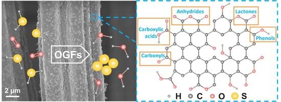
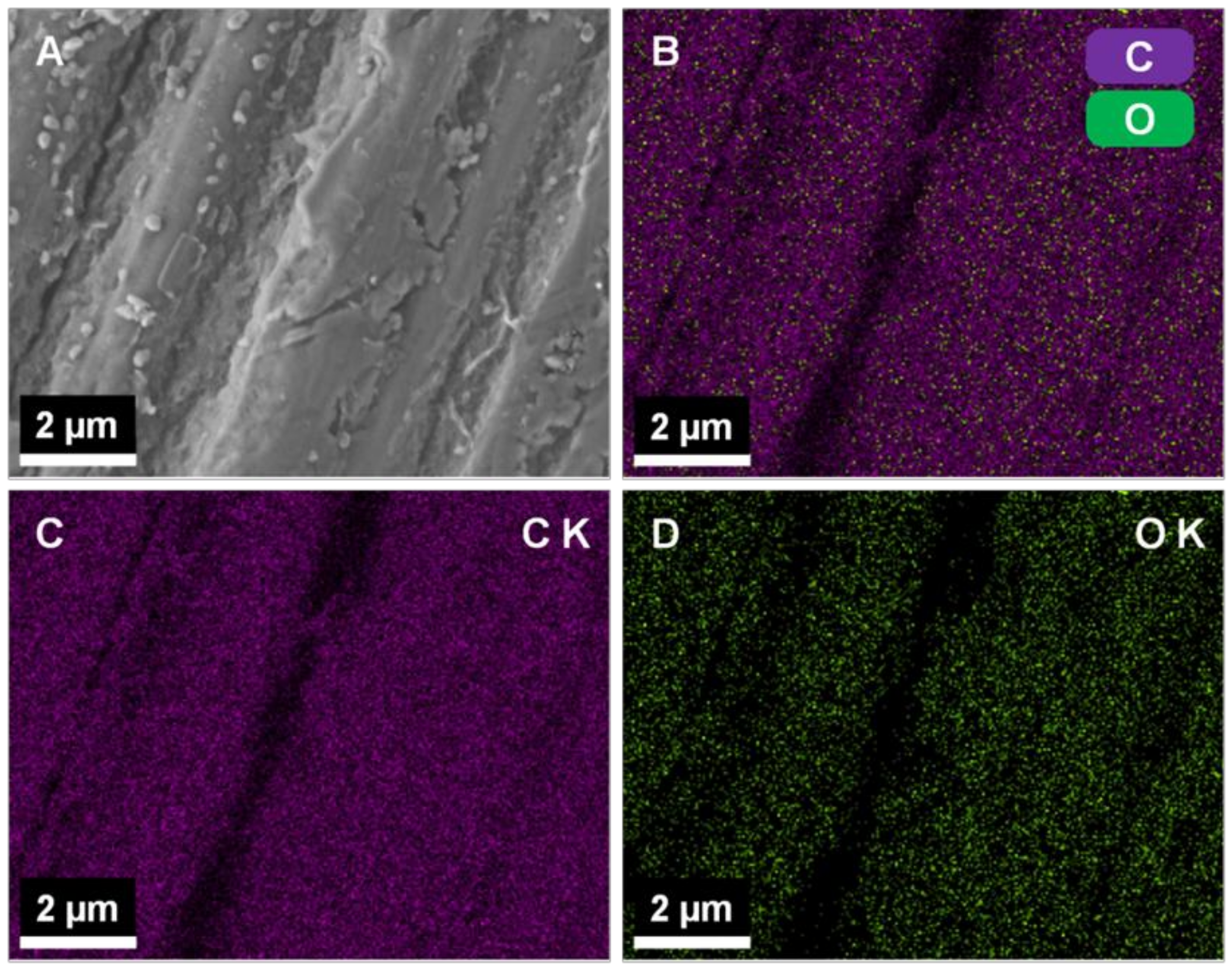
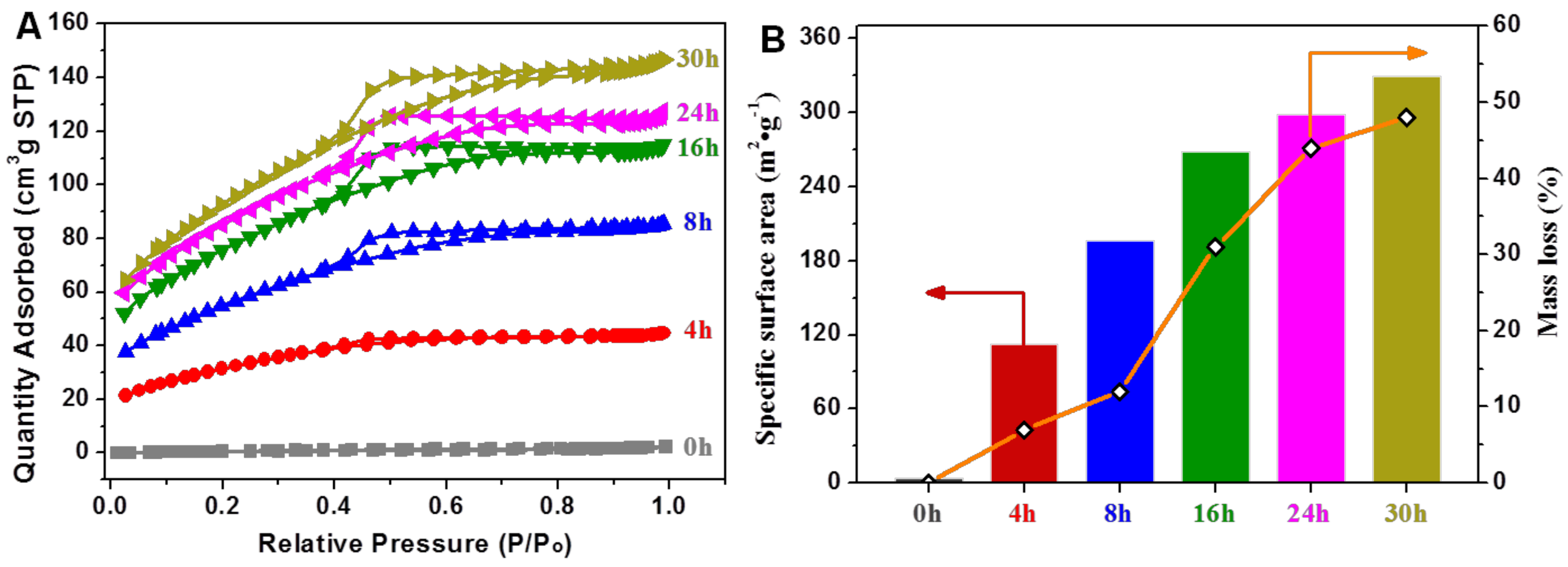
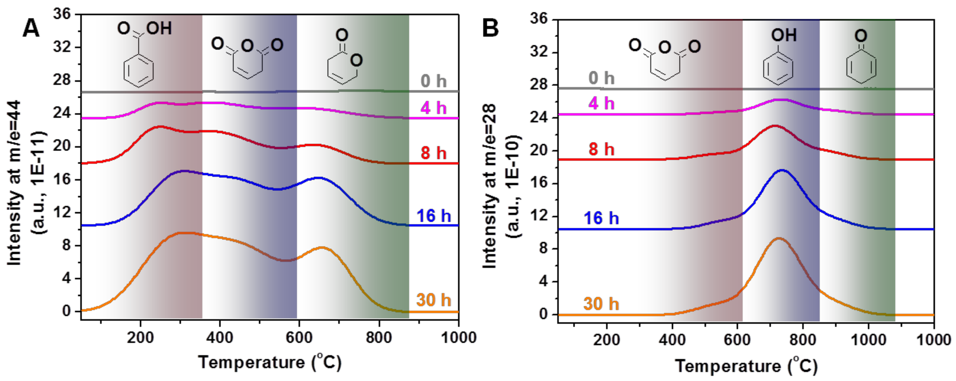
2.1. Characteristics of the Acid Treated Graphite Felts

The macroscopic shape of the filamentous GFs was completely retained after the gaseous HNO3 treatment according to scanning electron microscopy (SEM) micrographs with difference magnifications presented in Figure 1A–D. The HNO3 treated filamentous GFs was decorated with evenly distributed carbon nodules as evidenced by the SEM analysis (Figure 1D,E). High magnification SEM micrographs (Figure 1E,F) also evidence the formation of cracks and holes on the cross section of the OGFs sample (indicated by arrows). Such cracks could be attributed to the degradation of the graphite structure during the acid treatment. It is worthy to note that the acid treatment also leads to the formation of a rougher graphite surface (Figure 1F) compared to the smooth one for the pristine graphite material. Such roughness could be attributed to the formation of defects on the surface of the treated sample.
High-resolution SEM image (Figure 2A) evidences the formation of defects on the whole surface of the carbon filamentous and some carbon extrusion in the form of discrete nodules. The Energy Dispersive X-ray analysis (EDX) carried out on the sample evidences the presence of oxygen intimately linked with carbon on the surface of the acid treated sample surface (Figure 2B–D) which confirms the high concentration of oxygenated functional groups decorating the surface defects.
For industrial applications, the catalyst should be prepared in a controlled macroscopic shape in order to avoid problems of handling and transport and also to prevent excessive pressure drop within the catalyst bed. In the present synthesis method, the GFs can be prepared with different macroscopic shapes, i.e., pellets, disk with different holes, depending to the downstream applications as shown in Figure 3. The as-synthesized GFs could be directly used as metal-free catalyst, see catalytic application below, or also as catalyst support where the defective surface could lead to a high metal dispersion and stability. The macroscopic shape allows easy catalyst/products separation for liquid-phase catalytic processes which represents a costly process in the case of powdered catalysts.
According to our previous work on carbon nanotubes, the acid treatment lead to the formation of defects on the surface of the carbon material which was decorated by oxygenated functional groups. Such defects are expected to be formed through oxidative reaction between the gaseous nitric acid vapors and the graphite sample. The functionalization of the formed defects is expected to take place by the partial decomposition of the oxygen in the gas-phase medium. The formation of defects along the graphite microfilamentous surface during the acid treatment step also significantly increases the overall specific surface area (SSA) of the as-treated materials. The specific surface area of the acid treated filamentous GFs steadily increased as a function of the acid treatment duration as evidenced in Figure 4A,B. According to the results, the SSA of the filamentous GFs was stepwise raised from 10 m2/g to more than 300 m2/g after the gaseous HNO3 treatment for 30 h. It should be noted that such high SSA has never been accounted for chemical treated commercial microfilamentous carbon fibers. The increase of the SSA was attributed to the formation of a more porous graphite structure with higher effective surface area consecutive to the removal of carbon during the treatment from the sample (see transmission electron microscopy (TEM) analysis below). It is expected that such porosity was formed in or close to the surface of the carbon filaments and thus, allows the complete maintenance of the macroscopic shape of the material. One cannot exclude some porosity network which could be generated inside the pristine graphite microfilamentous.
The gaseous acid treatment also induces an overall oxidation of carbon matrix leading to a weight loss of the treated material compared to that of the pristine one. Such phenomenon has already been reported by Xia and co-workers with a similar treatment [37] and also by several groups in the literature [18]. The weight loss during the acid treatment process is accounted for the corrosion of the filaments where part of the carbon with low degree of graphitization was removed leaving behind the carbon nodules or porosity as observed by SEM. The weight loss calculated on the basis of the initial weight and the one after acid treatment as a function of the treatment duration is presented in Figure 4B.
It is expected that the corrosion phenomenon which occurring during the treatment was responsible for the increase of the SSA of the treated samples similarly to that reported for the carbon nanotubes treated with gaseous HNO3 or O3-H2O mixture [16,25]. The treatment induces the formation of surface pores along the carbon fiber axis, i.e., corrosion, which significantly contribute to the improvement of the overall SSA of the treated samples. These defects are also the place for oxygen insertion to generate oxygenated functional groups on the surface of the OGFs samples as evidenced by X-ray photoelectron spectroscopy (XPS) presented below.
The weight loss increases with the treatment duration, especially for durations longer than 8 h. It is expected that the low temperature weight loss could be assigned to the removal of pore amorphous carbon, since they are considered to be more reactive than the graphitic carbon filamentous while at high temperature, weight loss is linked with the removal of carbon in the graphitic structure consecutive to the formation of structural defects and nodules on the remained filament wall. Indeed, under a more severe treatment, i.e., longer duration, the weight loss becomes significantly, i.e., the weight loss recorded for the sample after being treated at 250 °C for 8 h and 24 h are 12% and 44%, respectively. According to the results the graphite displayed three distinct weight loss regions: (i) at treatment duration <8 h, the oxidation process is relatively slow which could be attributed to the low reactivity of the graphite felt surface; (ii) at treatment ranged between 8 to 24 h, the oxidation rate is significantly increased and could be due to the depth oxidation of graphite matter through the surface defects generated previously; and (iii) at duration >24 h, the oxidation process becomes almost flat which could be attributed to the fact that depth oxidation process could be hinder due to some diffusion problem.
The oxygen incorporation into the acid treated samples can be clearly observed through XPS survey spectra recorded on the fresh and HNO3 treated samples (Figure 5A). It is worthy to note that XPS analysis allows one to map out elements concentration at a depth of ca. 6 nm from the surface and thus part of the oxygenated functional groups localized at a distance >6 nm cannot be accurately detected. The deconvoluted O1s spectrum in Figure 5B shows the presence of three peaks which can be assigned to the C=O (ketone, aldehyde, quinone…), –C–OH, –C–O–C– (alcohol, ether), and –O–C=O (carboxylic, ester) oxygen species [25].
Raman spectroscopy was performed to investigate the change in the graphitic structure of the GFs after treatment with gaseous nitric acid at different durations. As shown in Figure 5C, every sample displayed three bands corresponding to the different carbonaceous structures: the G band attributed to an ideal graphitic lattice at around 1580 cm−1 [38]; the D band (~1350 cm−1) associated with the structural defects [39]; and D’ corresponding to the disordered graphitic fragments at ~1620 cm−1 [40], respectively. The ID/IG ratio increases as increasing the acid treatment duration (Figure 5D). After the treatment of 24 h, the ID/IG increased from 0.77 for GFs to 1.86. Meanwhile ID’/IG increased more than three times from 0.26 to 0.80, which indicated the strong acidic oxidant etched the graphene lattice of GFs and created more defects and disordered graphitic fragments. Furthermore, the greater duration of the treatment on samples, the more structural defects and disordered fragments that were obtained. Consistent with the morphology from SEM, the etching effect of the treatment made the GFs with an extremely rough surface and much more macroscopic carbon fragments. Moreover, the G band shifted to the higher wavenumber by about 8 cm−1, which may be attributed to the oxygen-containing functional groups generated on the surface of treated samples and confirmed by the results of XPS and temperature-programmed desorption (TPD), such as the O–H bending and C=O stretching [41].
The physical characteristics of the samples after acid treatment with different durations are summarized in Table 1.
TEM analysis is also used to investigate the influences of the HNO3 treatment on the microstructure of the GFs (Figure 6). Compared with parallel graphitic layers on pristine GFs (Figure 6A,B), there are porous structures with disordered graphitic fragments formed on the outer region of the filamentous carbon of the acid treated GFs (pointed out by arrows in Figure 6C,D), which are consistent with the analysis of SSA and by Raman. TEM analysis reveals the formation of a less dense graphite structure in the OGFs sample (Figure 6C) compared to that observed for the pristine GFs (Figure 6B). High resolution TEM micrographs (Figure 6D) clearly evidence the porous structure of the treated sample. Such phenomenon can be attributed to the oxidation of a weakly graphitized carbon by the gaseous HNO3 during the treatment, which forms entangled carbon sidewalls with high defect density.
According to the TEM results one could expected that during the acid treatment process part of the graphitic structure is slowly attacked, leading to a weight loss as a function of time of treatment, leaving behind porous structure with defects which contributes to an increase of the material SSA with time. Such corrosion process explains the formation of cracks and holes within the pristine graphite filamentous as observed by SEM. The as generated porosity with a highly defective surface decorated with oxygenated functional groups is expected to be of great interest for being used either as metal-free catalyst but also as catalyst support with high density of anchorage sites for hosting metal or oxide nanoparticles. Recent work has pointed out the high efficiency of defects decorated carbon nanotubes after treatment in the presence of ozone and water for anchoring gold nanoparticles [42]. The porous structure of the OGFs will be investigated in detail by mean of transmission electron microscopy tomography (TEM-3D) technique [43] to map out the porosity of the OGFs material and its influence on the metal nanoparticles dispersion.
The characterization of the different oxygenated groups present on the graphite surface was investigated by temperature-programmed desorption coupled with mass spectroscopy (TPD-MS). The surface oxygen groups can be assessed by the type of released molecules with their relevant peak areas and decomposition temperatures [44]. The amount of CO (m/e = 28) and CO2 (m/e = 44) generated during the TPD process is presented in Figure 7 as a function of the desorption temperature. The evolution of CO2 was ascribed to the decomposition of carboxylic acids, anhydrides, and lactones (Figure 7A), whereas the CO evolution was resulted from the decomposition of anhydrides, phenols, and carbonyls (Figure 7B). The amounts of corresponding groups determined by TPD with the deconvolution of evolved CO2 and CO peaks are summarized in Table 2. The CO and CO2 concentration increases as increasing the treatment duration, confirming that the formation of oxygenated functional groups is directly depending to the acid treatment, which is in accordance with the XPS analysis (Figure 5A,B).
It is expected that the acid treatment duration increases the defect density which in turn increases the amount of oxygenated functional groups directly linked to such defects. Furthermore, the total amount of oxygen on the sample increased from 165 µmol/g, on the pristine GFs, to 9116 µmol/g, on the OGFs-30, after 30 h of gas-phase oxidation treatment. Such results have already been reported by other research groups in the literature during acid activation process for the synthesis of highly reactive carbon-based catalyst supports [45]. However, data deals with the use of such defective macroscopic OGF materials with high effective surface area as metal-free catalyst has never been reported so far.
Thermogravimetry analysis (TG/DTG) has been generally used to study the oxidative stability of carbon materials [46,47,48]. As shown in Figure 8, all the samples exhibited a weight loss step during heat-treatment process, resulted from the combustion of carbon at high temperature. Obviously, the temperature of weight loss peak for OGFs-16 on the DTG curve (685 °C) was lower than that of the pristine GFs (802 °C), indicating the formation of highly reactive graphite species on the sample after the oxidation process. Meanwhile, a further decline of the oxidation temperature was observed for the OGF-24 (612 °C) with the longer treatment duration, i.e., 24 h instead of 16 h. On one hand, these reactive carbon species may be linked with the presence of structural defects or from the disordered graphitic structure, according to the Raman and TEM results (Figure 5C and Figure 6), which display lower thermal stability than the pristine graphite material [49]. On the other hand, higher SSA (Figure 4) of OGFs provides higher surface contact between the sample and reactant gas which could favor the oxidation process. Moreover, the abundant oxygen functional groups derived from acid treatment (Table 2) could be active sites for the dissociative adsorption of O2 [40]. It is expected that all those parameters will actively contribute to the lower oxidative resistance of the acid treated graphite felt.

2.2. OGFs as Metal-Free Catalyst for Selective Oxidation of H2S

The GFs and OGFs-16 catalysts were tested in the gas-phase selective oxidation of H2S into elemental sulfur under realistic reaction conditions. The OGFs-16 catalyst has been chosen among the other treated samples according to the following facts: (i) the OGFs-16 displays a relatively high SSA along with a lower weight loss during the acid treatment and (ii) the OGFs-16 also displays higher oxidative resistance compared to the samples treated with longer duration. The pristine GFs catalyst shows no noticeable desulfurization activity under the operated reaction conditions (not reported) and confirms its inactivity for the reaction considered. The desulfurization performance obtained on the OGFs-16 catalyst at reaction temperature of 230 °C and 250 °C is presented in Figure 9A as a function of time on stream. The OGFs-16 catalyst displays a relative high H2S conversion at a Weight Hourly Space Velocity (WHSV) of 0.05 h−1 with a total H2S conversion of 87% and a sulfur selectivity of 83%. In addition, it is worthy to note that the desulfurization activity remains stable as a function of time-on-stream for more than several dozen hours on stream, which indicates that no deactivation occurred on the catalyst. Such relatively high desulfurization activity could be attributed to the high stability of the defect decorated with oxygenated functional groups on the OGFs-16 catalyst which are generated at a relatively high treatment temperature, i.e., 250 °C. Similar results have also been reported by the HNO3 treated carbon nanotubes (CNTs) which is expected to bear the same active center [16]. Jiang et al. [50] have reported that pure carbon nanocages, which possess abundant holes, edges, and positive topological disclinations display a relatively good oxygen reductive performance which is even better than those reported for undoped CNTs. In the present work, the control of the macroscopic shape of the OGFs catalyst represents also a net advantage as the catalyst shape can be modified in a large range depending to the downstream applications.
Increasing the reaction temperature from 230 °C to 250 °C leads to an improvement of the H2S conversion, i.e., 99% instead of 87%, along with a slight decrease of the sulfur selectivity from 83% to 77% due to the fact that high reaction temperature favors the complete oxidation of S to SO2 in the presence of excess oxygen in the feed [51]. However, after a period of induction where both H2S conversion and sulfur selectivity are modified the catalyst reached a steady-state for the rest of the test which again confirm its high stability.
Increasing the WHSV from 0.05 h−1 to 0.1 h−1, keeping the reaction temperature at 250 °C, leads to a slight decrease of the H2S conversion from 100% to 90% followed by a steady-state (Figure 9B). The sulfur selectivity slightly increases from 75% to 82% at high space velocity and remains stable for the test. Such results are in good agreement with literature results as increasing the WHSV leads to a shorter sojourn time of the reactant and thus, reduce the rate of reactant dissociation for the reaction. The specific activity calculated is 0.56 molH2S/gcatalyst/h which is relatively close to those reported for other metal-free catalysts [52]. Further improvement of the catalytic performance could be done by using compressed OGFs with higher specific weight in order to reduce the empty space inside the catalyst bed.
The results obtained indicate that the OGF metal-free catalyst displays relatively high sulfur selectivity, i.e., >70%, even at a relatively high reaction temperature, i.e., 250 °C, and in the presence of a high H2S concentration. It is expected that such sulfur selectivity is linked with the high thermal conductivity of the graphite felt support which could efficiently disperse the reaction heat through the catalyst matrix to avoid local hot spots formation which is detrimental for the sulfur selectivity. Similar results have also been reported on the medium thermal conductive silicon carbide carrier where the lack of local hot spots leads to a significant improvement of the reaction selectivity for selective oxidation of H2S [10] and also in other exothermal reactions such as Fisher-Tropsch synthesis [53,54], dimethyl ether [55,56], and propylene synthesis [57,58]. The relatively high sulfur selectivity observed in the present work could also be attributed to the presence of large voids inside the sample which could favor the rapid evacuation of the sulfur intermediate species before complete oxidation.
The effluents containing H2S could be originated from different sources with various steam concentrations ranged from few to several percent, i.e., effluent from biogas plant or from the Claus reactor. It is expected that the steam concentration could have a significant influence on the desulfurization performance, i.e., H2S conversion and sulfur selectivity, due to the problem of competitive adsorption. The influence of steam concentration was investigated and the results are presented in Figure 10. Decreasing the steam concentration in the reactant feed from 30% to 10% leads to a similar H2S conversion, i.e., 99%, but to a significant increase of the sulfur selectivity from 75% to 85% keeping other reaction conditions similar. Such result indicates that steam could condense to yield water film inside the catalyst porosity, even at a relatively high reaction temperature, which favors oxygen dissociation leading to a higher complete oxidation to yield SO2. Decreasing the steam concentration leads to a lower oxygen atoms available on the catalyst surface which in turn, reduces the selectivity towards SO2. Such hypothesis can be confirmed by decreasing the O2-to-H2S ratio keeping the other reaction conditions similar. Decreasing the O2-to-H2S ratio seems to have hardly affected the sulfur selectivity while a slight decrease of the H2S conversion is observed. Such result could be attributed to the fact that the dissociated oxygen on the catalyst surface reacts with H2S to yield both S and SO2 in a parallel reaction pathway but with a different reaction rate. Decreasing the O2-to-H2S ratio leads to a decrease of the available oxygen for the reaction and, as a consequence lowers the H2S conversion. Finally, regarding the influence of steam on the H2S conversion it should be noted that under the reaction conditions used the H2S conversion is almost complete which could render the investigation of small effect, such as steam concentration, difficult as at such high conversion level one cannot rule out the fact that some active sites remain unemployed.
It is worthy to note that the reaction temperature of 250 °C is slightly higher than that usually used for the selective oxidation of H2S into elemental sulfur on other metal-free carbon-based catalysts. However, on the OGFs-16 metal-free catalyst the sulfur selectivity remains relatively high, i.e., >70% and even ≥85% at low steam concentration (Figure 10), at almost complete conversion of H2S. Such results could be attributed to the large open porosity of the catalyst, i.e., 90% of empty space, which allow the formed sulfur to rapidly escape the catalyst before secondary reaction with excess oxygen to yield SO2.
It is also noted that the catalyst displays also a relatively high stability, both in terms of H2S conversion and sulfur selectivity under severe reaction conditions, i.e., 0.1 h−1 of WHSV and high reaction temperature where the H2S conversion is not complete indicating that all the active sites were involved in the reaction, which confirm again the advantage of the oxygenated functional groups on the defect sites. Such results are of high interest as usually on oxides or metals containing catalysts sintering is the main cause of deactivation with time on stream under severe reaction conditions.
The results obtained indicate that acid treated graphite felts could be efficiently used as metal-free catalyst for the selective oxidation of H2S into elemental sulfur. The different catalytic results are summarized in Table 3 and compared with those reported on other metal-free catalysts. The OGFs-16 catalyst displays a relatively high sulfur selectivity compared to the other metal-free catalysts operated at higher space velocity and temperature. Such results pointed out the high efficiency of the OGFs-16 catalyst to perform selective oxidation of H2S which could be attributed to the large open porosity of the catalyst providing high rate of intermediate sulfur escaping.

3. Materials and Methods

3.1. Graphite Felts

The commercial filamentous GFs, ex-polyacrinonitrile (PAN), with a dimension of 1 × 3 m2 (thickness of 6 mm) was supplied by Carbone Lorraine (MERSEN, La Défense, France). The as-received GFs was shaped in the form of disks (Ø × thickness of 4 × 6 mm) for the experiment. The GFs displays a relatively low specific surface area, 10 ± 2 m2/g measured by means of N2 adsorption, which is mostly linked with the geometric surface area in good agreement with the extremely low porosity of the material. It is worthy to note that the GFs can be also shaped in various dimensions including pellets, disks or complexes structures, depending to the downstream applications, i.e., gas- or liquid-phase reactions, which represent a net advantage compared to other metal-free catalysts where low-dimensional shape is a main concern for further industrial development.

3.2. Gaseous HNO3 Treatment of GFs

For the gaseous acid treatment, as shown in Figure 11, the GFs was first oxidized at moderate temperature (500 °C) in air for 1 h in order to remove as much as possible residue from it surface. The as-treated pre-shaped GFs was loaded inside a tubular reactor (15 × 100 mm) and heated to the desired temperature of 250 °C by an external electrical furnace. The treatment temperature was fixed at 250 °C according to the previous investigation results reported by Duong-Viet et al. [16]. The treatment temperature was controlled by a thermocouple inserted inside the furnace. The reactor containing GFs in the form of disk (Ø × thickness of 4 × 6 mm) was connected to a round bottom flask filled with 150 mL of HNO3 with a concentration of 65% (SIGMA-ALDRICH, Saint-Quentin Fallavier, France). The temperature of the round bottom flask was fixed at 125 °C and the HNO3 solution was keep under magnetic stirring. The gaseous acid passed through the GFs bed was further condensed in another flask which can be re-used for the process and thus, reducing in a significant manner the problem linked with liquid waste recycling and recovery. The sample was treated with different durations in order to rule out the influence of these treatments on its final microstructure and chemical properties and to correlate these physical properties with the catalytic activity. The sample was washed with deionized water after the acid treatment and oven dried at 130 °C for overnight. In this work, the GFs after acid treated are noted as follows: OGFs-X, for the treatment duration in hour, for example: OGFs-24 indicates that the raw GFs were treated for 24 h under gaseous HNO3. It is noted that the treatment is not only limited to small amount of catalyst as higher amount of GFs can be also prepared by changing the reactor size.

3.3. Characterization Techniques

The scanning electron microscopy (SEM) and elemental mapping were carried out on a ZEISS GeminiSEM 500 microscope (ZEISS, Oberkochen, Germany) with a resolution of 5 nm. The sample was deposited onto a double face graphite tape in order to avoid the problem of charging effect during the analysis.
The Raman analysis was carried out using a LabRAM ARAMIS confocal microscope spectrometer (HORIBA, Kyoto, Japan) equipped with CCD detector. A laser line with the following characteristics was used to excite sample, 532 nm/100 mW (YAG) with Laser Quantum MPC600 PSU (Novanta, Bedford, OH, USA).
The specific surface area of the sample was determined in a Micromeritics sorptometer (Micromeritics, Norcross, GA, USA). The sample was outgassed at 250 °C under vacuum for 14 h in order to desorb moisture and adsorbed species on its surface.
The X-ray photoelectron spectroscopy (XPS) measurements of the support and catalyst were performed by using a MULTILAB 2000 (THERMO) spectrometer (Thermo Fisher Scientific, Waltham, MA, USA) equipped with an AlKα anode (hν = 1486.6 eV) with 10 min of acquisition to achieve a good signal to noise ratio. Peak deconvolution was performed with the “Avantage” program from the Thermoelectron Company. The C1s photoelectron binding energy was set at 284.6 ± 0.2 eV relative to the Fermi level and used as reference to calibrate the other peak positions.
The transmission electron microscopy (TEM) analysis was performed on a JEOL 2100F instrument (JEOL, Tokyo, Japan) working at a 200 kV accelerated voltage, equipped with a probe corrector for spherical aberrations, and with a point-to-point resolution of 0.2 nm. The sample was ground and dispersed by ultrasound in an acetone solution for 5 min and then a drop of the solution was deposited on a copper grid covered with a holey carbon membrane for observation.
The temperature-programmed desorption coupled with mass spectroscopy (TPD-MS) (Micromeritics, Norcross, GA, USA) experiments were carried out under helium flow at atmospheric pressure. The sample was flushed under helium for 30 min at room-temperature and then the temperature was raised from room-temperature to 1000 °C with a heating rate of 10 °C /min. The resulting gases, mostly CO (m/z signal at 28) and CO2 (m/z signal at 44) were continuously monitored with a time interval of 0.1 s.

3.4. Selective Oxidation Process

The catalytic selective oxidation of H2S by oxygen (Equation (1)) was carried out in an all glass microreactor working isothermally at atmospheric pressure. During the reaction other secondary reactions could also take place: consecutive oxidation of the formed sulfur with an excess of oxygen or direct oxidation of H2S to yield SO2 (Equations (2) and (3)). The temperature was controlled by a K-type thermocouple and a Minicor regulator. The gas mixture was passed downward through the catalyst bed. Before the test, the reactor was flushed with helium at room temperature until no trace of oxygen was detected at the outlet. The helium flow was replaced by the one containing steam. The catalyst was slowly heated up to the reaction temperature, and then the wet helium flow was replaced by the reactant mixture. The gases (H2S, O2, He) flow rate was monitored by Brooks 5850TR mass flow controllers (Brooks Instrument, Hatfield, PA, USA) linked to a control unit. The composition of the reactant feed was H2S (1 vol. %), O2 (1.25 vol. % or 2.5 vol. %), H2O (10 vol. % or 30 vol. %) and He (balance). The use of a relatively high concentration of steam in the feed is motivated by the will to be as close as possible to the industrial working conditions as the steam formed during the former Claus units is not removed before the oxidation step and remains in the treated tail gas. The steam (10 vol. % or 30 vol. %) was fed to the gas mixture by bubbling a helium flow through a liquid tank containing water maintained at 56 °C or 81 °C. The O2-to-H2S molar ratio was varied from 1.25 to 2.5 with a Weight Hourly Space Velocity (WHSV) at 0.05 h−1 or 0.1 h−1. It is worth to note that the WHSV used in the present work is close to the usual WHSV used in the industrial process for this kind of reaction, i.e., 0.09 h−1 [59].
H2S + 1/2 O2 → 1/n Sn + H2O    ∆H = −222 kJ·mol−1
1/n Sn + O2 → SO2    ∆H = −297 kJ·mol−1
H2S + 3/2 O2 → SO2 + H2O    ∆H = −519 kJ·mol−1
The reaction was conducted in a continuous mode and the sulfur formed during the reaction was vaporized, due to the relatively high partial pressure of sulfur at these reaction temperatures, and was further condensed at the exit of the reactor in a trap maintained at room temperature.
The analysis of the inlet and outlet gases was performed on-line using a Varian CP-3800 gas chromatography (GC) (Agilent, Santa Clara, CA, USA) equipped with a Chrompack CP-SilicaPLOT capillary column coupled with a thermal conductivity detector (TCD), allowing the detection of O2, H2S, H2O, and SO2. The limit detection of the H2S and SO2 is about 10 ppm. The results are reported in terms of H2S conversion and sulfur selectivity in percent. The percent of sulfur and SO2 selectivity is calculated on a basis of 100%. The sulfur balance is calculated on the basis of the sum of sulfur detected in the solid sulfur recovered in the cold trap and the selectivity towards SO2 and the theoretical sulfur calculated from the H2S conversion on the catalyst. The sulfur balance is about 92% and the difference could be attributed to (i) some dissolution of SO2 into the condensed water at the exit of the reactor and (ii) the incomplete recovery of the solid sulfur in the cold trap.

4. Conclusions

In summary, we have shown that oxidation with gaseous HNO3 can be an efficient and elegant pre-activation step to generate active metal-free carbon-based catalysts decorated with surface defects containing oxygenated functional groups from available and low cost commercial filamentous graphite felts. The gaseous acid treatment leads to the formation of a high surface area carbon-based material which can find use in several catalytic processes as either metal-free catalyst or as catalyst support. It is worthy to note that it is the first time that such results are reported as literature only reports metal-free catalysts based on nanocarbons, whose synthesis requires harsh reaction conditions along with the problem linked with waste treatment. According to the obtained results the defects created on the filamentous carbon wall and the formation of oxygenated functional groups during the gaseous acid treatment provide active sites for H2S and oxygen adsorption which contribute to the selective oxidation of H2S into elemental sulfur under similar reaction conditions with those operated in the industrial plants. The catalyst displays a relatively high sulfur selectivity as well as relatively high stability as a function of time-on-stream, under severe reaction conditions, indicating that deactivation by surface fouling or oxygen groups removing is unlikely to occur. The high specific surface area as well as surface porous structure could be extremely helpful for developing new catalytic systems. Such hierarchical metal-free catalysts can be prepared with different macroscopic shapes for subsequence downstream applications. Work is ongoing to evaluate such carbon-based materials as hierarchical macroscopic support for metal nanoparticles which could find use in other catalytic processes where high dispersion and strong anchorage of the active phase are required in order to prevent long term deactivation through catalyst sintering (gas-phase reaction) or leaching (liquid-phase reaction) and also in terms of recovery.

Acknowledgments

Zhenxin Xu and Bing Li would like to thank the Chinese Scholarship Council (CSC) for the PhD grant for their stay at the ICPEES. The project is partly supported by the National Foundation for Science and Technology Development of Vietnam (Nafosted) program of research. The SEM experiments were carried out at the facilities of the ICPEES-IPCMS platform. Vasiliki Papaefthimiou, Thierry Romero, and Sécou Sall (ICPEES, UMR 7515) are gratefully acknowledged for performing XPS, TPD-MS, and SEM experiments. Jean-Mario Nhut (ICPEES) is gratefully acknowledged for technical and scientific help during the project. Loïc Vidal (IS2M, UMR 7361) is gratefully acknowledged for TEM experiments.

Author Contributions

Z.X., C.D.-V., and C.P.-H. conceived and design the experiments; H.B., Z.X., and C.D.-V. participated in the analytical experiments; T.T.-H., H.B., Z.X., C.D.-V., B.L., C.P.-H., and L.N.-D. participated in the discussion and interpretation of the data. Z.X., C.D.-V., and C.P.-H. wrote the article.

Conflicts of Interest

The authors declare no conflict of interest.

References

  1. Su, D.S.; Perathoner, S.; Centi, G. Nanocarbons for the development of advanced catalysts. Chem. Rev. 2013, 113, 5782–5816. [Google Scholar] [CrossRef] [PubMed]
  2. Tessonnier, J.P.; Su, D.S. Recent progress on the growth mechanism of carbon nanotubes: A review. ChemSusChem 2011, 4, 824–847. [Google Scholar] [CrossRef] [PubMed]
  3. Duong-Viet, C.; Ba, H.; Truong-Phuoc, L.; Liu, Y.; Tessonnier, J.P.; Nhut, J.M.; Granger, P.; Pham-Huu, C. Nitrogen-Doped Carbon Composites as Metal-Free Catalysts; Elsevier Series Book; Parvulescu, V., Kemnitz, E., Eds.; Elsevier: Amsterdam, The Netherlands, 2016; pp. 273–312. ISBN 978-0-444-63587-7. [Google Scholar]
  4. Liang, J.; Du, X.; Gibson, C.; Du, X.W.; Qiao, S.Z. N-doped graphene natively grown on hierarchical ordered porous carbon for enhanced oxygen reduction. Adv. Mater. 2013, 25, 6226–6231. [Google Scholar] [CrossRef] [PubMed]
  5. Wei, W.; Liang, H.; Parvez, K.; Zhuang, X.; Feng, X.; Mullen, K. Nitrogen-doped carbon nanosheets with size-defined mesopores as highly efficient metal-free catalyst for the oxygen reduction reaction. Angew. Chem. Int. Ed. 2014, 53, 1570–1574. [Google Scholar] [CrossRef] [PubMed]
  6. Tang, Y.; Allen, B.L.; Kauffman, D.R.; Star, A. Electrocatalytic activity of nitrogen-doped carbon nanotube cups. J. Am. Chem. Soc. 2009, 131, 13200–13201. [Google Scholar] [CrossRef] [PubMed]
  7. Gong, K.; Du, F.; Xia, Z.; Durstock, M.; Dai, L. Nitrogen-doped carbon nanotube arrays with high electrocatalytic activity for oxygen reduction. Science 2009, 323, 760–764. [Google Scholar] [CrossRef] [PubMed]
  8. Liu, Y.; Jin, Z.; Wang, J.; Cui, R.; Sun, H.; Peng, F.; Wei, L.; Wang, Z.; Liang, X.; Peng, L.; et al. Nitrogen-doped single-walled carbon nanotubes grown on substrates: Evidence for framework doping and their enhanced properties. Adv. Funct. Mater. 2011, 21, 986–992. [Google Scholar] [CrossRef]
  9. Tuci, G.; Pilaski, M.; Ba, H.; Rossin, A.; Luconi, L.; Caporali, S.; Pham-Huu, C.; Palkovits, R.; Giambastiani, G. Unraveling surface basicity and bulk morphology relationship on covalent triazine frameworks with unique catalytic and gas adsorption properties. Adv. Funct. Mater. 2017, 27, 1605672. [Google Scholar] [CrossRef]
  10. Chizari, K.; Deneuve, A.; Ersen, O.; Florea, I.; Liu, Y.; Edouard, D.; Janowska, I.; Begin, D.; Pham-Huu, C. Nitrogen-doped carbon nanotubes as a highly active metal-free catalyst for selective oxidation. ChemSusChem 2012, 5, 102–108. [Google Scholar] [CrossRef] [PubMed]
  11. Zhang, J.; Qu, L.; Shi, G.; Liu, J.; Chen, J.; Dai, L. N, P-codoped carbon networks as efficient metal-free bifunctional catalysts for oxygen reduction and hydrogen evolution reactions. Angew. Chem. Int. Ed. 2016, 55, 2230–2234. [Google Scholar] [CrossRef] [PubMed]
  12. Tuci, G.; Zafferoni, C.; Rossin, A.; Luconi, L.; Milella, A.; Ceppatelli, M.; Innocenti, M.; Liu, Y.; Pham-Huu, C.; Giambastiani, G. Chemical functionalization of N-doped carbon nanotubes: A powerful approach to cast light on the electrochemical role of specific N-functionalities in the oxygen reduction reaction. Catal. Sci. Technol. 2016, 6, 6226–6236. [Google Scholar] [CrossRef]
  13. Lv, R.; Cui, T.; Jun, M.-S.; Zhang, Q.; Cao, A.; Su, D.S.; Zhang, Z.; Yoon, S.-H.; Miyawaki, J.; Mochida, I.; et al. Open-ended, N-doped carbon nanotube-graphene hybrid nanostructures as high-performance catalyst support. Adv. Funct. Mater. 2011, 21, 999–1006. [Google Scholar] [CrossRef]
  14. Ba, H.; Liu, Y.; Truong-Phuoc, L.; Duong-Viet, C.; Nhut, J.-M.; Nguyen, D.L.; Ersen, O.; Tuci, G.; Giambastiani, G.; Pham-Huu, C. N-doped food-grade-derived 3D mesoporous foams as metal-free systems for catalysis. ACS Catal. 2016, 6, 1408–1419. [Google Scholar] [CrossRef]
  15. Tuci, G.; Luconi, L.; Rossin, A.; Berretti, E.; Ba, H.; Innocenti, M.; Yakhvarov, D.; Caporali, S.; Pham-Huu, C.; Giambastiani, G. Aziridine-functionalized multiwalled carbon nanotubes: Robust and versatile catalysts for the oxygen reduction reaction and knoevenagel condensation. ACS Appl. Mater. Interfaces 2016, 8, 30099–30106. [Google Scholar] [CrossRef] [PubMed]
  16. Duong-Viet, C.; Liu, Y.; Ba, H.; Truong-Phuoc, L.; Baaziz, W.; Nguyen-Dinh, L.; Nhut, J.-M.; Pham-Huu, C. Carbon nanotubes containing oxygenated decorating defects as metal-free catalyst for selective oxidation of H2S. Appl. Catal. B 2016, 191, 29–41. [Google Scholar] [CrossRef]
  17. Qi, W.; Liu, W.; Guo, X.; Schlogl, R.; Su, D. Oxidative dehydrogenation on nanocarbon: Intrinsic catalytic activity and structure-function relationships. Angew. Chem. Int. Ed. 2015, 54, 13682–13685. [Google Scholar] [CrossRef] [PubMed]
  18. Pereira, M.F.R.; Órfão, J.J.M.; Figueiredo, J.L. Oxidative dehydrogenation of ethylbenzene on activated carbon catalysts. I. Influence of surface chemical groups. Appl. Catal. A 1999, 184, 153–160. [Google Scholar] [CrossRef]
  19. Avilés, F.; Cauich-Rodríguez, J.V.; Moo-Tah, L.; May-Pat, A.; Vargas-Coronado, R. Evaluation of mild acid oxidation treatments for mwcnt functionalization. Carbon 2009, 47, 2970–2975. [Google Scholar] [CrossRef]
  20. Hiura, H.; Ebbesen, T.W.; Tanigaki, K. Opening and purification of carbon nanotubes in high yields. Adv. Mater. 1995, 7, 275–276. [Google Scholar] [CrossRef]
  21. Qui, N.V.; Scholz, P.; Krech, T.; Keller, T.F.; Pollok, K.; Ondruschka, B. Multiwalled carbon nanotubes oxidized by UV/H2O2 as catalyst for oxidative dehydrogenation of ethylbenzene. Catal. Commun. 2011, 12, 464–469. [Google Scholar] [CrossRef]
  22. Mahata, N.; Pereira, M.F.; Suarez-Garcia, F.; Martinez-Alonso, A.; Tascon, J.M.; Figueiredo, J.L. Tuning of texture and surface chemistry of carbon xerogels. J. Colloid Interface Sci. 2008, 324, 150–155. [Google Scholar] [CrossRef] [PubMed]
  23. Simmons, J.M.; Nichols, B.M.; Baker, S.E.; Marcus, M.S.; Castellini, O.M.; Lee, C.-S.; Hamers, R.J.; Eriksson, M.A. Effect of ozone oxidation on single-walled carbon nanotubes. J. Phys. Chem. B 2006, 110, 7113–7118. [Google Scholar] [CrossRef] [PubMed]
  24. Huang, R.; Xu, J.; Wang, J.; Sun, X.; Qi, W.; Liang, C.; Su, D.S. Oxygen breaks into carbon nanotubes and abstracts hydrogen from propane. Carbon 2016, 96, 631–640. [Google Scholar] [CrossRef]
  25. Luo, J.; Liu, Y.; Wei, H.; Wang, B.; Wu, K.-H.; Zhang, B.; Su, D.S. A green and economical vapor-assisted ozone treatment process for surface functionalization of carbon nanotubes. Green Chem. 2017, 19, 1052–1062. [Google Scholar] [CrossRef]
  26. Hu, J.; Guo, Z.; Chu, W.; Li, L.; Lin, T. Carbon dioxide catalytic conversion to nano carbon material on the iron–nickel catalysts using CVD-IP method. J. Energy Chem. 2015, 24, 620–625. [Google Scholar] [CrossRef]
  27. Liu, Y.; Dintzer, T.; Ersen, O.; Pham-Huu, C. Carbon nanotubes decorated α-Al2O3 containing cobalt nanoparticles for fischer-tropsch reaction. J. Energy Chem. 2013, 22, 279–289. [Google Scholar] [CrossRef]
  28. Więckowska, J. Catalytic and adsorptive desulphurization of gases. Catal. Today 1995, 24, 405–465. [Google Scholar] [CrossRef]
  29. Zhang, X.; Tang, Y.; Qu, S.; Da, J.; Hao, Z. H2S-selective catalytic oxidation: Catalysts and processes. ACS Catal. 2015, 5, 1053–1067. [Google Scholar] [CrossRef]
  30. Bashkova, S.; Baker, F.S.; Wu, X.; Armstrong, T.R.; Schwartz, V. Activated carbon catalyst for selective oxidation of hydrogen sulphide: On the influence of pore structure, surface characteristics, and catalytically-active nitrogen. Carbon 2007, 45, 1354–1363. [Google Scholar] [CrossRef]
  31. Shinkarev, V.V.; Glushenkov, A.M.; Kuvshinov, D.G.; Kuvshinov, G.G. Nanofibrous carbon with herringbone structure as an effective catalyst of the H2S selective oxidation. Carbon 2010, 48, 2004–2012. [Google Scholar] [CrossRef]
  32. PiéPlu, A.; Saur, O.; Lavalley, J.-C.; Legendre, O.; NéDez, C. Claus catalysis and H2S selective oxidation. Catal. Rev. Sci. Eng. 1998, 40, 409–450. [Google Scholar] [CrossRef]
  33. Liu, Y.; Duong-Viet, C.; Luo, J.; Hébraud, A.; Schlatter, G.; Ersen, O.; Nhut, J.-M.; Pham-Huu, C. One-pot synthesis of a nitrogen-doped carbon composite by electrospinning as a metal-free catalyst for oxidation of H2S to sulfur. ChemCatChem 2015, 7, 2957–2964. [Google Scholar] [CrossRef]
  34. Keller, N.; Pham-Huu, C.; Ledoux, M.J. Continuous process for selective oxidation of H2S over SiC-supported iron catalysts into elemental sulfur above its dewpoint. Appl. Catal. A 2001, 217, 205–217. [Google Scholar] [CrossRef]
  35. Lee, E.-K.; Jung, K.-D.; Joo, O.-S.; Shul, Y.-G. Catalytic wet oxidation of H2S to sulfur on V/MgO catalyst. Catal. Lett. 2004, 98, 259–263. [Google Scholar] [CrossRef]
  36. Claus Process. Available online: https://en.wikipedia.org/wiki/Claus_process (accessed on 3 April 2018).
  37. Xia, W.; Jin, C.; Kundu, S.; Muhler, M. A highly efficient gas-phase route for the oxygen functionalization of carbon nanotubes based on nitric acid vapor. Carbon 2009, 47, 919–922. [Google Scholar] [CrossRef]
  38. Cancado, L.G.; Jorio, A.; Ferreira, E.H.; Stavale, F.; Achete, C.A.; Capaz, R.B.; Moutinho, M.V.; Lombardo, A.; Kulmala, T.S.; Ferrari, A.C. Quantifying defects in graphene via raman spectroscopy at different excitation energies. Nano Lett. 2011, 11, 3190–3196. [Google Scholar] [CrossRef] [PubMed]
  39. Sadezky, A.; Muckenhuber, H.; Grothe, H.; Niessner, R.; Pöschl, U. Raman microspectroscopy of soot and related carbonaceous materials: Spectral analysis and structural information. Carbon 2005, 43, 1731–1742. [Google Scholar] [CrossRef]
  40. Datsyuk, V.; Kalyva, M.; Papagelis, K.; Parthenios, J.; Tasis, D.; Siokou, A.; Kallitsis, I.; Galiotis, C. Chemical oxidation of multiwalled carbon nanotubes. Carbon 2008, 46, 833–840. [Google Scholar] [CrossRef]
  41. Thanh, T.T.; Ba, H.; Truong-Phuoc, L.; Nhut, J.-M.; Ersen, O.; Begin, D.; Janowska, I.; Nguyen, D.L.; Granger, P.; Pham-Huu, C. A few-layer graphene–graphene oxide composite containing nanodiamonds as metal-free catalysts. J. Mater. Chem. A 2014, 2, 11349–11357. [Google Scholar] [CrossRef]
  42. Luo, J.; Wei, H.; Liu, Y.; Zhang, D.; Zhang, B.; Chu, W.; Pham-Huu, C.; Su, D.S. Oxygenated group and structural defect enriched carbon nanotubes for immobilizing gold nanoparticles. Chem. Commun. 2017, 53, 12750–12753. [Google Scholar] [CrossRef] [PubMed]
  43. Ersen, O.; Hirlimann, C.; Drillon, M.; Werckmann, J.; Tihay, F.; Pham-Huu, C.; Crucifix, C.; Schultz, P. 3D-TEM characterization of nanometric objects. Solid State Sci. 2007, 9, 1088–1098. [Google Scholar] [CrossRef]
  44. Figueiredo, J.L. Functionalization of porous carbons for catalytic applications. J. Mater. Chem. A 2013, 1, 9351–9364. [Google Scholar] [CrossRef]
  45. Shi, W.; Zhang, B.; Lin, Y.; Wang, Q.; Zhang, Q.; Su, D.S. Enhanced chemoselective hydrogenation through tuning the interaction between pt nanoparticles and carbon supports: Insights from identical location transmission electron microscopy and X-ray photoelectron spectroscopy. ACS Catal. 2016, 6, 7844–7854. [Google Scholar] [CrossRef]
  46. Scheibe, B.; Borowiak-Palen, E.; Kalenczuk, R.J. Oxidation and reduction of multiwalled carbon nanotubes—Preparation and characterization. Mater. Charact. 2010, 61, 185–191. [Google Scholar] [CrossRef]
  47. Chu, W.; Ran, M.; Zhang, X.; Wang, N.; Wang, Y.; Xie, H.; Zhao, X. Remarkable carbon dioxide catalytic capture (CDCC) leading to solid-form carbon material via a new cvd integrated process (CVD-IP): An alternative route for CO2 sequestration. J. Energy Chem. 2013, 22, 136–144. [Google Scholar] [CrossRef]
  48. Bom, D.; Andrews, R.; Jacques, D.; Anthony, J.; Chen, B.; Meier, M.S.; Selegue, J.P. Thermogravimetric analysis of the oxidation of multiwalled carbon nanotubes: Evidence for the role of defect sites in carbon nanotube chemistry. Nano Lett. 2002, 2, 615–619. [Google Scholar] [CrossRef]
  49. Ran, M.; Sun, W.; Liu, Y.; Chu, W.; Jiang, C. Functionalization of multi-walled carbon nanotubes using water-assisted chemical vapor deposition. J. Solid State Chem. 2013, 197, 517–522. [Google Scholar] [CrossRef]
  50. Jiang, Y.; Yang, L.; Sun, T.; Zhao, J.; Lyu, Z.; Zhuo, O.; Wang, X.; Wu, Q.; Ma, J.; Hu, Z. Significant contribution of intrinsic carbon defects to oxygen reduction activity. ACS Catal. 2015, 5, 6707–6712. [Google Scholar] [CrossRef]
  51. Shinkarev, V.V.; Glushenkov, A.M.; Kuvshinov, D.G.; Kuvshinov, G.G. New effective catalysts based on mesoporous nanofibrous carbon for selective oxidation of hydrogen sulfide. Appl. Catal. B 2009, 85, 180–191. [Google Scholar] [CrossRef]
  52. Duong-Viet, C.; Truong-Phuoc, L.; Tran-Thanh, T.; Nhut, J.-M.; Nguyen-Dinh, L.; Janowska, I.; Begin, D.; Pham-Huu, C. Nitrogen-doped carbon nanotubes decorated silicon carbide as a metal-free catalyst for partial oxidation of H2S. Appl. Catal. A 2014, 482, 397–406. [Google Scholar]
  53. Liu, Y.; Ersen, O.; Meny, C.; Luck, F.; Pham-Huu, C. Fischer–tropsch reaction on a thermally conductive and reusable silicon carbide support. ChemSusChem 2014, 7, 1218–1239. [Google Scholar] [CrossRef] [PubMed]
  54. Lacroix, M.; Dreibine, L.; de Tymowski, B.; Vigneron, F.; Edouard, D.; Bégin, D.; Nguyen, P.; Pham, C.; Savin-Poncet, S.; Luck, F.; et al. Silicon carbide foam composite containing cobalt as a highly selective and re-usable Fischer–Tropsch synthesis catalyst. Appl. Catal. A 2011, 397, 62–72. [Google Scholar] [CrossRef]
  55. Elamin, M.M.; Muraza, O.; Malaibari, Z.; Ba, H.; Nhut, J.-M.; Pham-Huu, C. Microwave assisted growth of SAPO-34 on β-SiC foams for methanol dehydration to dimethyl ether. Chem. Eng. J. 2015, 274, 113–122. [Google Scholar] [CrossRef]
  56. Liu, Y.; Podila, S.; Nguyen, D.L.; Edouard, D.; Nguyen, P.; Pham, C.; Ledoux, M.J.; Pham-Huu, C. Methanol dehydration to dimethyl ether in a platelet milli-reactor filled with H-ZSM5/SiC foam catalyst. Appl. Catal. A 2011, 409–410, 113–121. [Google Scholar] [CrossRef]
  57. Jiao, Y.; Yang, X.; Jiang, C.; Tian, C.; Yang, Z.; Zhang, J. Hierarchical ZSM-5/SiC nano-whisker/SiC foam composites: Preparation and application in mtp reactions. J. Catal. 2015, 332, 70–76. [Google Scholar] [CrossRef]
  58. Duong-Viet, C.; Ba, H.; El-Berrichi, Z.; Nhut, J.-M.; Ledoux, M.J.; Liu, Y.; Pham-Huu, C. Silicon carbide foam as a porous support platform for catalytic applications. New J. Chem. 2016, 40, 4285–4299. [Google Scholar] [CrossRef]
  59. Mares, B.; Prosernat Com. Personal communication, 2018.
Figure 1. Scanning electron microscopy (SEM) micrographs of the (A,B) pristine commercial graphite felts (GFs), and (C,D) the same after treatment under gaseous HNO3 at 250 °C for 24 h, noted oxidized graphite felts (OGFs)-24 showing the formation of nanoscopic nodules on its surface. SEM micrographs with medium and high resolution (E,F) reveal the formation of cracks on the cross section of the OGFs-24 (indicated by arrows) as well as a rougher surface after acid treatment.
Catalysts 08 00145 g001
Figure 2. (A) SEM micrograph of the acid treated graphite felts, OGFs-24, (B) Elemental mapping showing the presence of C and O on the sample surface. (C,D) Elemental maps of carbon and oxygen elements on the OGFs-24 surface.
Catalysts 08 00145 g002
Figure 3. Graphite felts with different macroscopic shapes for various catalytic applications both in gas- and liquid-phase processes.
Catalysts 08 00145 g003
Figure 4. N2 adsorption-desorption isotherms (A) and weight loss (open circles) and specific surface area (columns) modification of the acid treated carbon-based materials as a function of the treatment duration (B).
Catalysts 08 00145 g004
Figure 5. (A) Survey X-ray photoelectron spectroscopy (XPS) of OGFs-24 in comparison with pristine GFs, (B) deconvolution O1s present the oxygen species on the surface of the samples, (C) Raman spectra, and (D) ID/IG and ID’/IG ratios of the pristine GFs and the OGFs after acid treatment with various durations.
Catalysts 08 00145 g005
Figure 6. Transmission electron microscopy (TEM) images of GFs (A,B) and OGFs-24 (C,D). Surface defects generated on the OGFs are indicated by arrows.
Catalysts 08 00145 g006
Figure 7. Temperature-programmed desorption (TPD) profiles showing the evolvement of CO2 (A) and CO (B) as a function of the desorption temperature on the different oxidized samples at 250 °C and with different treatment duration.
Catalysts 08 00145 g007
Figure 8. Thermogravimetry analysis (TG/DTG) profiles of pristine GFs, OGFs-16 and OGFs-24.
Catalysts 08 00145 g008
Figure 9. Desulfurization performance as a function of time on stream on the OGFs-16 catalyst. (A) Reaction conditions: [H2S] = 1 vol. %, [O2] = 2.5 vol. %, [H2O] = 30 vol. %, Weight Hourly Space Velocity (WHSV) = 0.05 h−1; (B) Reaction conditions: [H2S] = 1 vol. %, [O2] = 2.5 vol. %, [H2O] = 30 vol. %, reaction temperature = 250 °C.
Catalysts 08 00145 g009
Figure 10. Influence of the steam concentration and O2-to-H2S ratio on the desulfurization performance on the pristine GFs and the one after treatment under gaseous HNO3 at 250 °C for 16 h (OGFs-16) catalysts. Reaction conditions: [H2S] = 1 vol. %, reaction temperature = 250 °C and WHSV = 0.05 h−1.
Catalysts 08 00145 g010
Figure 11. Schematic illustration of the OGFs prepared by the gaseous HNO3 treatment and the different oxygenated functional groups generated on the graphite surface after the treatment.
Catalysts 08 00145 g011
Table 1. The physical chemistry properties of samples as a function of the acid treatment duration.
Treatment DurationSSA a
m2/g
Mass Loss b
%
ID/IGcID’/IGcO
at % d
TWLe
°C
0 h1000.770.267.3802
4 h11271.640.55--
8 h19612----
16 h268311.830.66-685
24 h298441.860.809.4612
30 h32948----
a BET specific areas. b The mass loss of samples after acid treatment. c The ID/IG and ID’/IG ratio calculated from Raman spectra. d The atom percent of surface oxygen elemental from XPS analysis. e The temperature of weight loss peak determined by TG/DTG profiles. - Not detected.
Table 2. The content of oxygen functional groups as a function of the acid treatment duration at 250 °C on the samples determined from TPD profiles.
Treatment DurationCO2 Desorption µmol/gCO Desorption µmol/gTotal O µmol/g
Carboxylic AcidsAnhydridesLactonesAnhydridesPhenolsCarbonyls
0 h------165
4 h531871281419512301691
8 h13448614833221994983797
16 h30462641252738656606393
30 h422118642473554628879116
Table 3. Selective oxidation of H2S to sulfur over different metal-free catalysts.
CatalystsT
°C
[H2S]
vol. %
[O2]
vol. %
[H2O]
vol. %
WHSV
h1
XH2Sa
%
SSb
%
YSc
%
Ref.
OGFs-1625012.5100.1988684This work
O-CNT-250-2423012.5300.695767216
N-CNT/SiC-75019012.5300.697757352
a Maximum H2S conversion. b The corresponding sulfur selectivity. c The corresponding yield of sulfur. (YS = XH2S × SS).

