Hydrotreating of Light Cycle Oil over Supported on Porous Aromatic Framework Catalysts
by

Eduard Karakhanov
1,*, 
Anton Maximov
1,2,
Yulia Kardasheva
1,
Maria Vinnikova
1 and
Leonid Kulikov
1 1
Department of Petroleum Chemistry and Organic Catalysis, Moscow State University, Moscow 119991, Russia
2
Institute of Petrochemical Synthesis RAS, Moscow 119991, Russia
*
Author to whom correspondence should be addressed.
Catalysts 2018, 8(9), 397; https://doi.org/10.3390/catal8090397
Submission received: 21 August 2018
/
Revised: 12 September 2018
/
Accepted: 12 September 2018
/
Published: 14 September 2018
Abstract
:The hydroprocessing of substituted naphthalenes and light cycle oil (LCO) over bimetallic Ni-W-S and Ni-Mo-S catalysts that were obtained by decomposition of [N(n-Bu)4]2[Ni(MeS4)2] (Me = W, Mo) complexes in situ in the pores of mesoporous aromatic frameworks (PAFs) during the reaction, was studied. The promotion of acid-catalyzed processes by PAF-AlCl3, synthesized by impregnation of a PAF with AlCl3 from its toluene solution, was investigated. It has been found that Ni-W-S catalytic systems were more active in the hydrodearomatization reactions, while Ni-Mo-S catalytic systems were more active in hydrodesulfurization and hydrocracking reactions. The introduction of sulfur into the reaction medium enhanced the activity of the catalysts and the presence of PAF-AlCl3 led to an acceleration of the hydrocracking processes.
1. Introduction
Light cycle oil (LCO) is a middle distillate that is produced by fluid catalytic cracking of heavy gas oil or vacuum gas oils. It distils between 120 °C and 380 °C and contains high amounts of aromatic hydrocarbons (60–90 wt %) and sulfur (up to 9000 or 25,000 ppm depending on the quality of feedstock). LCO can be used as a blending component for diesel or fuel oil and it can be used as a feedstock for the manufacturing of diesel fuel. However, the ongoing toughening of ecological standards and restrictions for the levels of sulfur and aromatics in fuels makes the use of LCO for these purposes an increasingly unattractive choice.
LCO can be upgraded using hydrocatalytic processes—hydrodearomatization, hydrodesulfurization, hydrocracking. One of the most suitable technologies for the conversion of heavy oils is slurry-phase hydrocracking. This process includes the conversion of large, bulky molecules into smaller ones at the active sites of the catalyst. Therefore, it is crucial to have a system of macro- and meso-scale pores in the catalyst to allow for the mass transport of heavy feedstock to the active sites of catalyst to maximize its activity. Conventional catalysts for various hydroprocesses are mainly based on microstructured inorganic materials, such as zeolites and alumosilicates, in which pore sizes hamper the diffusion of large molecules into the material [1,2]. That is why mesostructured hierarchical materials are considered as a perspective base for the development of new generation catalysts.
In the last decade, various strategies for the synthesis of numerous mesoporous materials, both inorganic, organic and of a hybrid nature, were developed [3,4,5,6,7,8]. Inorganic supports are the most common ones due to the presence of acid sites in their structure that are necessary for the hydrocracking reactions to occur. However, they often interact with the active phase of catalyst—sulfides of transition metals, like tungsten and molybdenum, promoted with cobalt or nickel—and decrease their activity [9,10]. Organic supports are mainly deprived of this shortcoming, but they possess a much lower stability over the course of the reaction and cannot stabilize sulfide nanoparticles as well as inorganic supports. This problem could be solved by the synthesis of new classes of organic mesoporous materials, such as mesoporous phenol-formaldehyde polymers (MPFs) and porous aromatic frameworks (PAFs). They are formed by aromatic units, organized into a regular ordered structure. Due to the high values of surface area, mesoporous structure, chemical and thermal stability and affinity to organic molecules, these classes of materials are of interest to design catalysts for different processes [11,12,13].
Recently, we reported the synthesis of PAF- and MPF-based bimetallic sulfide catalysts using an in situ method and their examination in hydrodearomatization-hydrocracking reactions using naphthalene, methylnaphthalenes and anthracene as model substrates [14,15] and in the hydroconversion of LCO [16]. Catalysts, prepared using an in situ method, presented a better performance in the different hydroprocesses, particularly in hydrodesulfurization reactions [17,18]. However, it has been found that PAF-based catalysts possess low cracking and isomerization activities, probably due to the absence of acid groups in the structure of PAF. Thus, the presence of acid is necessary for the acceleration of these processes. In previous work, we showed that the introduction of a PAF-AlCl3 catalyst enhanced the cracking ability of PAF-NiMeS catalytic systems [19]. Herein we continue to investigate the properties of PAF-NiMeS/PAF-AlCl3 catalytic systems for the hydrotreating of substituted naphthalenes and LCO, particularly to ascertain the influence of the position and length of alkyl-groups in naphthalene molecules on the activity of the catalysts in cracking, isomerization and dearomatization reactions.
2. Results and Discussion
2.1. Characterization of Precursors and Catalysts
Thermal decomposition of [N(n-Bu)4]2[Ni(MeS4)2] (Me = W, Mo) within the pores of porous aromatic frameworks PAF (Figure 1) occurred over a wide temperature range in several steps. The probable decomposition pathway, according to Reference [20], with an amendment for the presence of nickel, can be represented as
[N(n-Bu)4]2[Ni(MeS4)2] = NiMe2S2−nCxNyHz + 2 N(n-Bu)3 + Bu2S2 + …
The coefficients n, x, y and z depend on the chemical composition of the salt. As for [N(n-Bu)4]2[WS4], the decomposition product could be presented as WS2C1.28N0.07H1.14 [20], and for [N(n-Bu)4]2[MoS4] the composition of the product is MoS2.03C1.13N0.04H0.8 [21].
The first two peaks of the differential thermal analysis and thermogravimetry (DTA-TG) curves can probably be related to the decomposition of the ammonium cation by the formation of N(n-Bu)3. It should be noted that there was a lag between the changing of the mass of the samples and the following decomposition processes. Thus, a mass decrease of approximately 16–19%, which was attributed to the formation of N(n-Bu)3, occurred right after the end of the exothermic peaks at 230–235 °C. This could be because of the diffusion limitations during the evaporation of the gaseous products of the decomposition as the [N(n-Bu)4]2[Ni(MeS4)2] salts are within the pores of the PAF. The endothermic peaks at 395 and 325 °C were attributed to the structural rearrangements within the products of the initial decomposition and/or the formation of a NiW2S5−nCxNyHz phase. Further decomposition peaks, above 400 °C, were attributed to the decomposition of the support material [22].
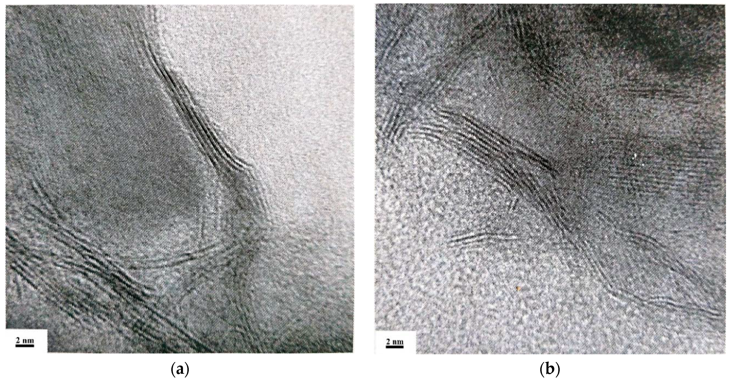
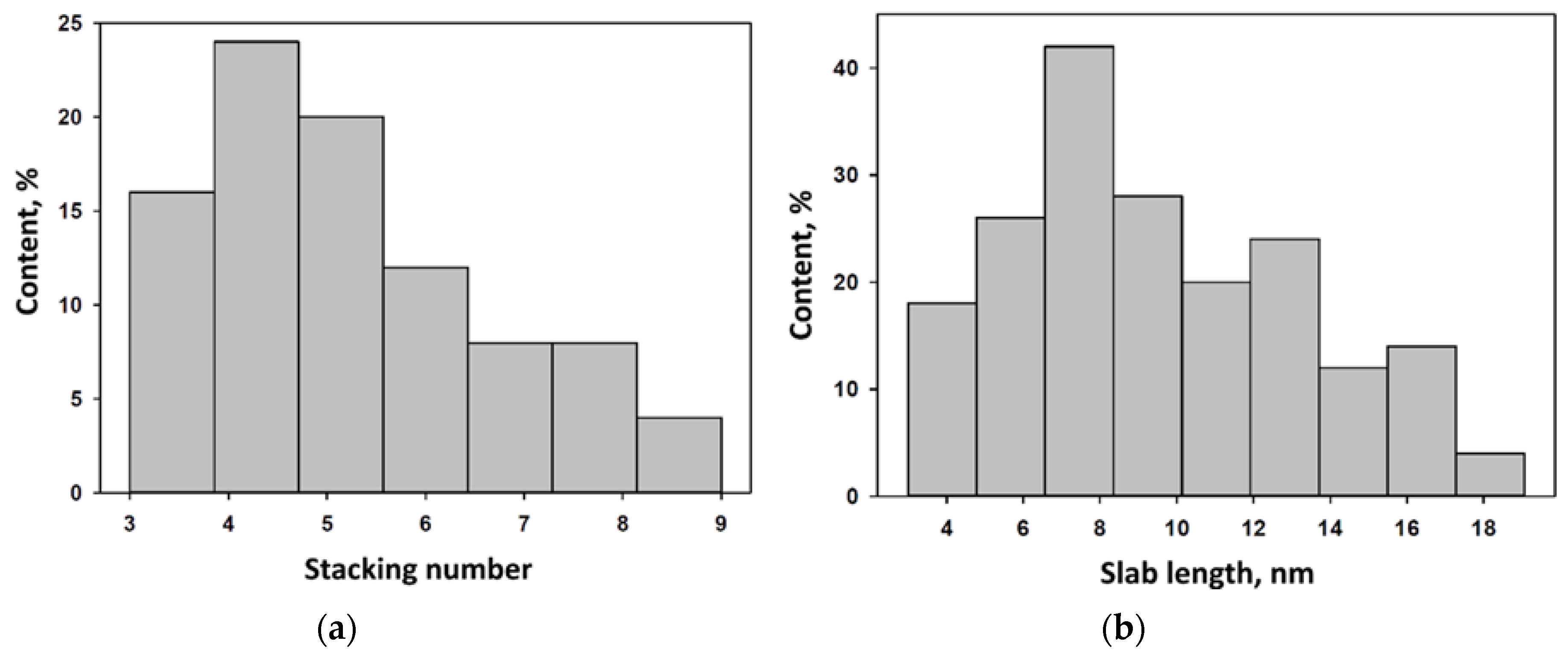
High-resolution transmission electron microphotographs (HRTEM) of particles of the PAF-NiWS catalyst, after the reaction of LCO hydroconversion, are seen in Figure 2. Such lamellar structures of particles, that consist of multiple layers, are typical for sulfide catalysts. Analogously to the previous work [14], the length, L, and the number, N, of three-dimensional stacked layers were measured (Figure 3). The stacking number for the PAF-NiWS catalyst varied from three to nine with a maximum of four to five slabs. The slab length varied from 3 nm to 19 nm with a maximum of 7 nm.
The average dimensions and stacking numbers of the sulfide particles for current and previous work are listed below in Table 1, where is the number of slabs per stack, D-MeS2 dispersion, and fe/fc is the edge-to-corner ratio of a sulfide slab. Calculations were performed using the previously listed equations [14,15].
The chemical composition of the surface of the catalysts was evaluated by means of X-ray photoelectron spectroscopy (XPS) analysis. The XPS spectra of the samples contained peaks for tungsten, molybdenum, nickel, sulfur, carbon, nitrogen and oxygen. The decomposition of W4f and Mo3d spectra showed the presence of three forms of metal on the surface of the catalyst: MeS2, MeSxOy and Me6+. The weight ratios and binding energies of the resultant phases are listed in Table 2. The obtained values for the binding energies were compared with those reported in the literature [23,24].
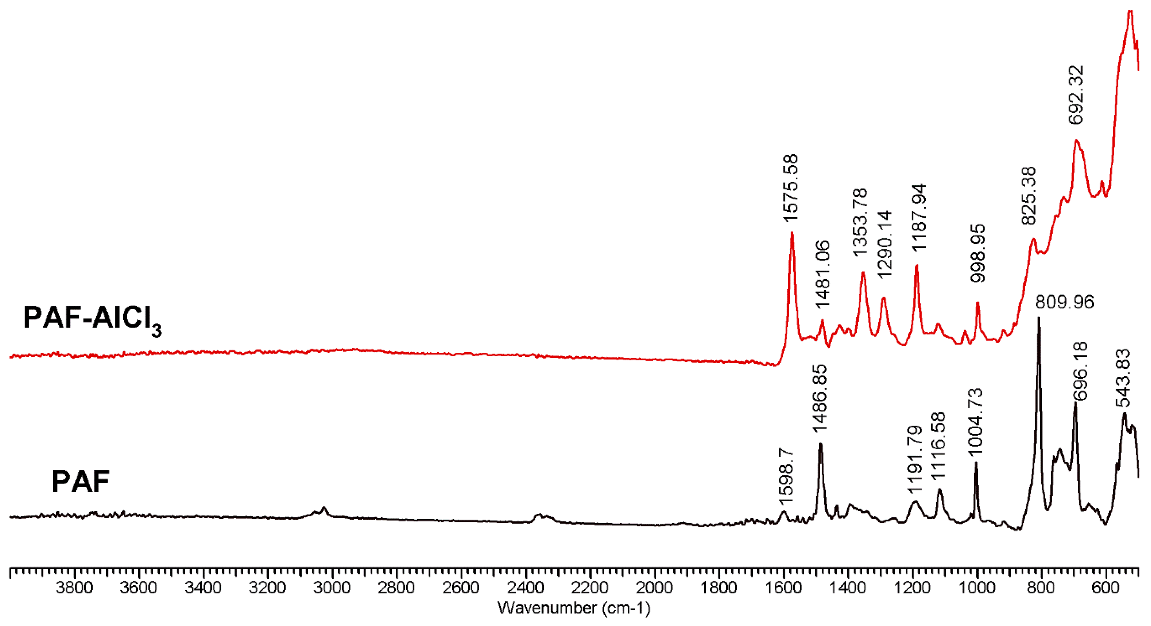
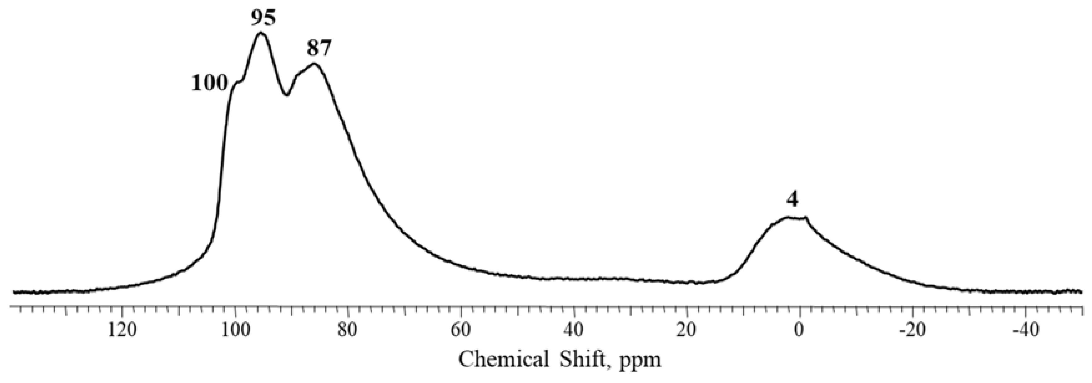
Recently, we described the synthesis of a PAF-AlCl3 catalyst and its use in the hydrogenation-hydrocracking of naphthalene [19]. It is well known that Lewis acids, particularly aluminum chloride, react with aromatic substances and form complexes of the type PhHσ+-(AlCl3)σ− through charge-transfer mechanisms [25,26,27]. We showed that this mechanism was realized also in the case of the interaction between AlCl3 and PAF. Thus, PAF-AlCl3, likewise for the PAF-SO3H [28,29,30] material, has blue color—appearing when electron-withdrawing groups interact with the polyaromatic skeleton of PAF. The FTIR spectrum of PAF-AlCl3 (Figure 4), similarly for the spectrum of PS-AlCl3 material in Reference [26], contains absorption bands with a maximum at 1580 cm−1, proving the formation of charge-transfer structures. In addition, the solid-state 27Al NMR spectrum (Figure 5) of PAF-AlCl3 contained signatures of a hexahedral substituted aluminum (approximately 5 ppm) and several AlxCly forms with tetra-coordinated aluminum, like [AlCl4]−, [Al2Cl7]−, [AlClx(OH)4−x]− [31,32,33].
2.2. Catalytic Experiments with Model Substrates
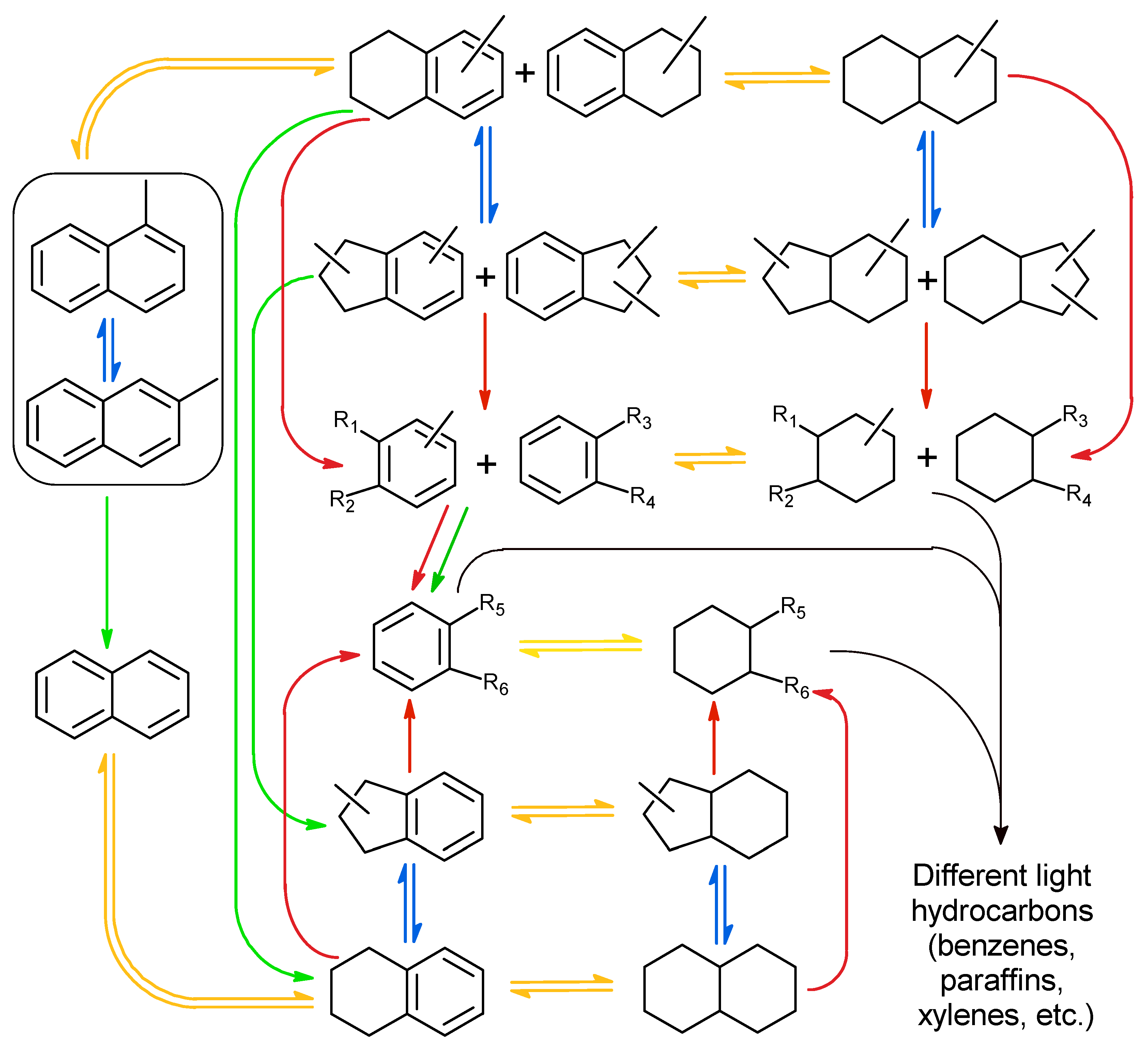
To investigate the properties of PAF-NiMeS/PAF-AlCl3 catalytic systems for the hydroconversion of substituted naphthalenes, experiments with 1-, 2-methylnaphthalenes, 2-ethylnaphthalene and 1,3-, 1,5-dimethylnaphthalenes were performed. These substances were chosen as LCO mainly contains different alkyl-derivatives of naphthalene and tetraline, and we assume that general patterns of activity for PAF-NiMeS/PAF-AlCl3 systems in hydrodearomatization, hydrocracking, isomerization and dealkylation reactions for LCO will be the same, as for model substrates. The aim of this part of the study was to elucidate the peculiarities of the conversion of molecules with different numbers of alkyl groups, their length and position. The simplified mechanism for the conversion of naphthalene and methylnaphtalenes into the reaction products is presented in Figure 6.
All reactions can be formally divided into four types: Hydrogenation reactions, also called hydrodearomatization reactions; isomerization reactions; hydrocracking reactions, which result in the destruction of C–C bonds in the carbon structure of molecule and the formation of new C–H bonds; and dealkylation reactions, which result in the destruction of C–C bonds between carbon atoms of the benzene ring, and the alkyl chain, and removal of the alkyl substituent from the structure of the molecule. Dealkylation reactions always result in a decrease in the number of carbon atoms in the molecule structure, while cracking reactions do not. For each molecule, the probability of entry into a particular type of the reaction depends on its structure, concentration, the activity of the catalytic system in this type of reaction, and other factors. It should be noted that the scheme in Figure 6 represents the main processes that occur during the hydrotreating of methylnaphthalenes, but does not include intramolecular condensation and transalkylation, coke formation and other side reactions.
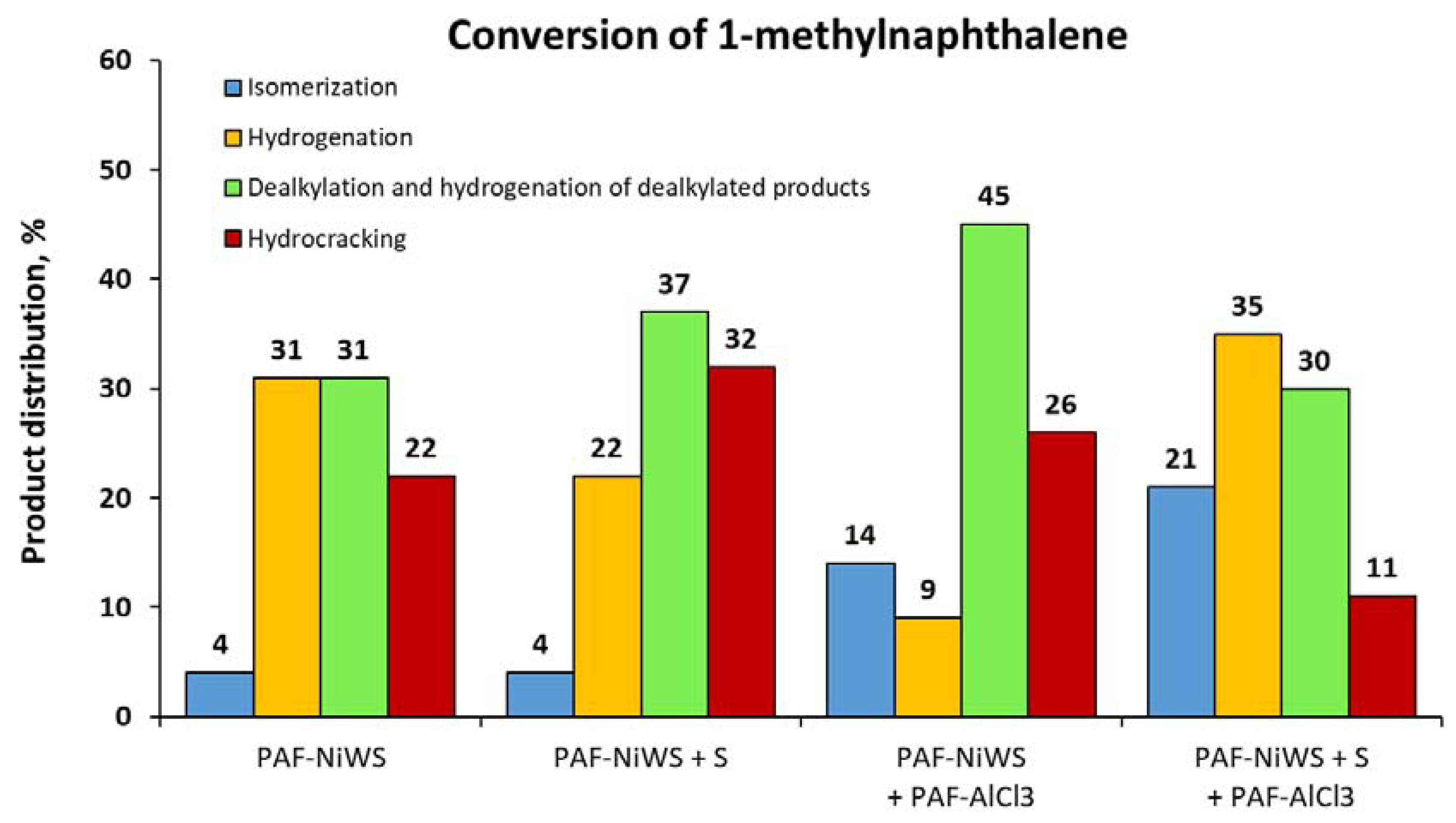
The results of hydrotreating of 1- and 2-methylnaphthalenes over the PAF-NiWS catalyst are presented in Figure 7 and Figure 8. 2-Methylnaphthalene underwent conversion to methyltetralines and methyldecalines—hydrogenation reaction products. The introduction of both sulfur and PAF-AlCl3 dramatically accelerated the rate of the dealkylation process and, to a lesser extent, the rate of the hydrocracking processes. In the case of experiments with 1-methylnaphthalene, the yields of products of isomerization, dealkylation and hydrocracking reactions were higher than in the case of 2-methylnaphthalene. The introduction of PAF-AlCl3 accelerated the isomerization of 1-methylnapthalene into 2-methylnaphthalene.
The catalytic system, consisting of PAF-NiWS, PAF-AlCl3, and sulfur, was tested for the conversion of 1,3-dimethylnaphthalene, 1,5-dimethylnaphthalene and 2-ethylnaphthalene (Figure 9). Notably, the yields of dealkylation and hydrocracking products grew by increasing of the number of alkyl groups in the structure of naphthalenes and their length. At the same time, sterically more hindered substrates were more likely to undergo dealkylation and hydrocracking reactions. In this regard, it could be concluded that when PAF-AlCl3 is present in the catalyst system, sterically hindered substrates are more prone to dealkylation and hydrocracking reactions compared to hydrogenation reactions.
2.3. Catalytic Experiments with Light Cycle Oil (LCO)
The use of the catalytic system PAF-NiMeS/PAF-AlCl3 could be most promising for hydrotreating LCO from the position of both hydrodearomatization, hydrocracking, hydroisomerization and hydrodesulphurization reactions. LCO contains a large number of aromatic compounds, mostly diaromatic (35–55 wt %) and monoaromatic (10–35 wt %) hydrocarbons, and to a lesser extent polyaromatic hydrocarbons (5–10 wt %) with three or more benzene rings in the structure [34]; the predominant diaromatic hydrocarbons are represented basically by different alkyl-substituted naphthalenes. The source of sulfur in LCO is various benzothiophenes and dibenzothiophenes, as well as disulfides in trace amounts. Depending on the fractional distillation temperature range and the feedstock and features of the manufacturing process, the content of the components in LCO could vary. LCO, which was used in the current work, is characterized by a high content of aromatic compounds (approximately 60 wt %). However, the distribution of mono- and diaromatic hydrocarbons was shifted towards the former. The sulfur content in the used feedstock was 0.35 wt %, or 3500 ppm, which is common for LCO.
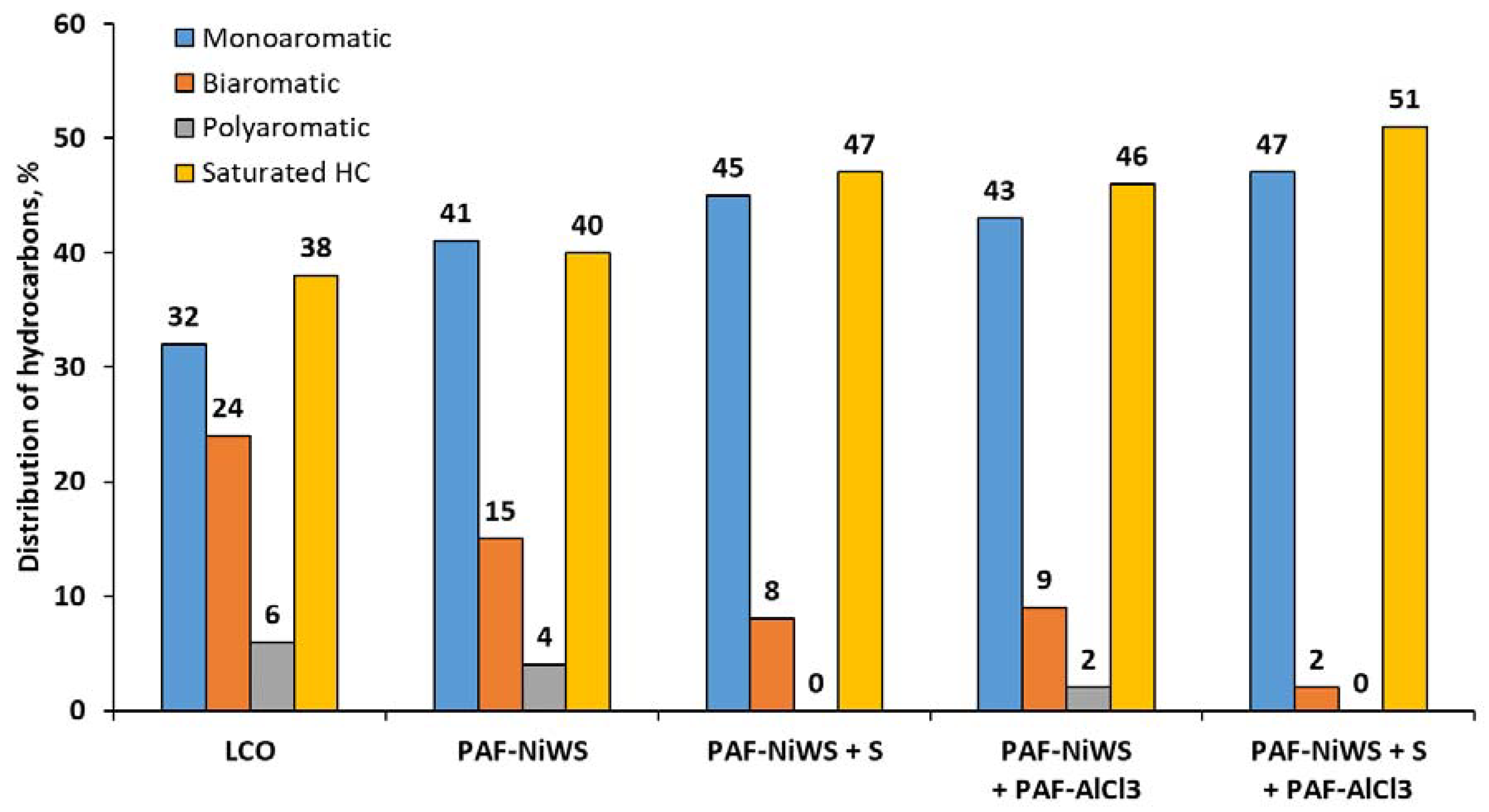
The results of the catalytic hydrotreating of LCO in the presence of PAF-NiWS and PAF-NiMoS catalysts are shown in the Figure 10, Figure 11 and Figure 12. The best results for the dearomatization process were obtained using the PAF-NiWS catalyst. Particularly, the application of the catalytic system PAF-NiWS + PAF-AlCl3 + S led to the highest yield of saturated compounds and the lowest content of di- and polyaromatic hydrocarbons. Remarkably, the reaction with PAF-NiMoS without PAF-AlCl3 did not lead to a notable decrease in the quantity of biaromatic and polyaromatic hydrocarbons. However, since the fractional composition of LCO shifted towards light hydrocarbons, this result may indicate the dominance of the reactions of dealkylation and cracking of alkyl chains over hydrogenation reactions. When PAF-AlCl3 was used as a promoter with the PAF-NiMoS catalyst, the yields of monoaromatic and saturated hydrocarbons increased, confirming the cracking activity of PAF-AlCl3. Thus, we can conclude that W-based catalysts are more active in hydrogenation/hydrodearomatization processes, while Mo-based catalysts are more active in hydrocracking and dealkylation processes. The obtained results are consistent with reported data for sulfide catalysts [35,36,37], according to which tungsten catalysts are more active in hydrodearomatization reactions compared to molybdenum ones.
Fractional composition of LCO after hyrdoconvertion with PAF-NiMeS catalytic systems is shown in Figure 12. The use of the PAF-NiWS catalyst, as well as of PAF-NiMoS catalyst, led to the displacement of the fractional composition of LCO towards lighter products. However, tungsten catalysts were more effective for the conversion of “heavy” fractions, especially of fractions that boil above 300 °C. The addition of sulfur did not lead to a significant change in the distribution of fractions, confirming its role as a promoter in hydrogenation reactions. In contrast, when the cracking-promoting additive PAF-AlCl3 was added to the reaction, more light hydrocarbons were formed. Combining data of the fractional composition of hydroconverted LCO and the distribution of aromatic hydrocarbons in it, it can be concluded that in the presence of tungsten catalysts, the reaction proceeds by hydrogenation of aromatic substances followed by their hydrocracking. At the same time, in presence of molybdenum catalysts, the reaction proceeded through hydrocracking and dealkylation mechanisms, and PAF-AlCl3 promoted the hydrocracking of heavy aromatics.
In addition, we determined the sulfur content in LCO after the reactions to assess the hydrodesulfurization activity of the catalysts (Figure 13). Hydrotreating over both tungsten and molybdenum catalysts allowed us to achieve a high level of desulfurization, reducing the sulfur concentration up to 10–20% from the initial content. The best results were obtained for the molybdenum catalyst PAF-NiMoS, for which the extent of desulfurization reached up to 90%. The use of tungsten catalysts made it possible to decrease the sulfur content to a level of 630–690 ppm, which could be explained by the lower activity of tungsten catalysts in hydrodesulfurization reactions compared to molybdenum catalysts [35,38].
3. Materials and Methods
3.1. Materials
All starting materials were purchased from commercial suppliers and used as received. The purification of solvents was performed according to standard methods. Porous aromatic frameworks were synthesized as described earlier [9]. LCO was received from Gazprom Nephtekhim Salavat, Ltd. Characteristics of LCO are listed in Table 3.
3.2. Synthesis of Precursors and Catalysts
The ammonium thiomolybdate and thiotungstate were prepared as described elsewhere [10]. The tetraalkylammonium nickel tetrathyometallate salts and PAF-NiMeS catalysts were obtained using the previously described method [6]. Both the tungsten and molybdenum content in the catalysts was 15 wt %.
Synthesis of the PAF-AlCl3 catalyst was performed by impregnation of PAF with AlCl3 from its hot toluene solution. The typical procedure includes dissolving of 2 g of AlCl3 in 200 mL of toluene at 100–105 °C, cooling of the solution to 80 °C and the addition of 1 g of PAF. Then, the mixture was stirred for 4 h, allowing it to cool to room temperature. After the removal of toluene, under reduced pressure, a dark-blue well-dispersed powder was obtained.
3.3. Characterization of Catalysts
DTA-TG measurements were conducted using the Paulik-Erdey MOM Q-1500D derivatograph (MOM, Budapest, Hungary) with the use of alumina crucibles under an air atmosphere within the temperature interval of 30–1000 °C and a heating rate of 10 °C/min.
The solid-state NMR 27Al spectra were recorded using a Brucker AVANCE-II 400 (Bruker UK Ltd., Coventry, UK) instrument with a magic angle spinning (MAS) at a resonance frequency of 104.23 MHz. The spinning speed was 12 kHz, 1 M aqueous solution of Al(NO3)3 was used as a standard.
The textural properties of the catalysts were determined from HRTEM microphotographs, obtained on a JEOL JEM-2100/Cs/GIF microscope (JEOL, Tokyo, Japan) with a 0.19 nm lattice fringe resolution and an accelerating voltage of 200 kV. The samples were prepared on a perforated carbon film, mounted on a copper grid, and 10–15 representative micrographs were obtained for each catalyst in high-resolution mode. Typically, the lengths of at least 400 slabs were measured for each catalyst.
The XPS analysis of the catalysts was performed on a VersaProbeII, ULVAC-PHI (ULVAC-PHI, Inc., Kanagawa, Japan) instrument using excitation with Al Kα X-ray radiation at 1486.6 eV. The calibration of the photoelectron peaks was based on the C 1s line with a binding energy of 286.7 eV. The transmission energy of the energy analyzer was 160 eV (a survey spectrum) or 40 eV (individual lines).
3.4. Catalytic Testing Procedure
The reactions were carried out in a steel reactor, equipped with a stir bar, at 380 °C under a 5 MPa H2 pressure. Typically, the stir bar, the PAF-NiMeS catalyst (200 mg), LCO (2 mL) or 30% solution of model substrates in undecane (2 mL), sulfur (200 mg, in several experiments), and PAF-AlCl3 (100 mg, in several experiments) were introduced into the reactor. Then the reactor was sealed and pressurized with H2 at the demanded pressure. The mixture was stirred at 380 °C and, after the reaction was finished, the reactor was cooled down and depressurized. The reaction products were analyzed by GC, HPLC and X-ray fluorescence analysis.
3.5. Gas Chromatography
The products of the hydrotreating of the model substrates were analyzed by gas chromatography using a Crystallux 4000 M chromatograph (NPF Meta-Chrom, Yoshkar-Ola, Russia) equipped with FID and a non-polar column Petrocol TM (Supelco) (50 m × 0.2 mm ID, 0.5 μm film). Program: 100 °C (5 min) → 20 °C/min → 200 °C (60 min). The carrier gas was helium, the flow rate was 20 mL/min. Chromatograms were calculated using NetChrom 2.1 software (NPF Meta-Chrom, Yoshkar-Ola, Russia).
The fractional composition of the liquid products of LCO hydrotreating was determined using a CHROMOS GC-1000 chromatograph (Chromos, Moscow, Russia), equipped with a flame ionization detector and applying a method, similar to the method of “Simulated distillation” [39]. Analysis conditions: gas consumption of carrier gas (helium)–42 mL/min, hydrogen–25 mL/min, air–250 mL/min; temperature of injector and detector were 370 °C, Column–RESTEK MXT-2887 (10 m × 0.53 mm ID, 2.65 μm film). Program: 35 °C (1 min) → 20 °C/min → 340 °C (15 min). Sample volume–1 μL. Fractional compositions of the cracking products were calculated using Chromos STO Gazprom 5.5 2007 v 0.9.18.0 software (Chromos, Moscow, Russia).
3.6. X-ray Fluorescence Analysis
The determination of the sulfur content of the reaction products was performed on Specroscan S equipment, using standard methods [40].
3.7. High Performance Liquid Chromatography
The content and distribution of aromatic hydrocarbons were determined using “GOST R EN 12916-2008: Petroleum products. Determination of the types of aromatic hydrocarbons in the middle distillates. The method of high-performance liquid chromatography with detection by the refractive index” standard. The analysis was performed using Knauer apparatus (Knauer, Berlin, Germany) with a SmartLine 2300 refractometric detector and a diasphere-amine column at a temperature of 20 °C in accordance with GOST R EN 12916-08 (ASTM 3591-06) standard [41].
4. Conclusions
The hydroconversion of various naphthalenes and LCO using the catalysts PAF-NiMeS (Me = Mo, W) with the addition of PAF-AlCl3 and sulfur was studied. It was found that the structure of the substrate molecule strongly influenced the mechanism of its transformation to the reaction products. Obviously, increasing the length of the alkyl chain increased the probability of the cracking reactions, and increasing of the number of the alkyl substituents increased the probability of the dealkylation reactions. However, the position of the substituent in the alkylnaphthalene molecule was an important factor. The probability of dealkylation and isomerization processes was higher when the substituent was in the α-position, whereas β-substituted naphthalenes underwent mainly hydrogenation.
We have also shown that the addition of PAF-AlCl3 to the catalytic system promoted various acid-catalyzed processes. Moreover, when PAF-AlCl3 was present in the catalyst system, sterically hindered substrates were more prone to dealkylation and hydrocracking reactions than hydrogenation reactions.
Based on the results of LCO hydrotreating, we can conclude that the PAF-NiWS catalyst was more active in hydrogenation/hydrodearomatization processes, while the PAF-NiMoS catalyst was more active in hydrocracking, dealkylation and desulfurization processes. In the case of the PAF-NiWS catalyst, the reaction followed through the hydrogenation of aromatic substances and further dealkylation, cracking and isomerization of hydrogenated products. In the case of the PAF-NiMoS catalyst, hydrocracking of alkyl chains in the substrate molecules prevailed.
Author Contributions
E.K. and A.M. conceived and designed the experiments; M.V. performed the experiments; Y.K. contributed reagents/materials/analysis tools; L.K. wrote the paper.
Funding
This research was funded by the Russian Science Foundation, grant number 15-19-00099.
Acknowledgments
The study was supported by the Russian Science Foundation within the framework of Project N 15-19-00099.
Conflicts of Interest
The authors declare no conflicts of interest.
References
- Primo, A.; Garcia, H. Zeolites as Catalysts in Oil Refining. Chem. Soc. Rev. 2014, 43, 7548–7561. [Google Scholar] [CrossRef] [PubMed]
- Ennaert, T.; Van Aelst, J.; Dijkmans, J.; De Clercq, R.; Schutyser, W.; Dusselier, M.; Verboekend, D.; Sels, B.F. Potential and Challenges of Zeolite Chemistry in the Catalytic Conversion of Biomass. Chem. Soc. Rev. 2016, 45, 584–611. [Google Scholar] [CrossRef] [PubMed]
- Wan, Y.; Zhao, D. On the Controllable Soft-Templating Approach to Mesoporous Silicates. Chem. Rev. 2007, 107, 2821–2860. [Google Scholar] [CrossRef] [PubMed]
- Srivastava, R. Synthesis and Applications of Ordered and Disordered Mesoporous Zeolites: Present and Future Prospective. Catal. Today 2018, 309, 172–188. [Google Scholar] [CrossRef]
- Bingre, R.; Louis, B.; Nguyen, P. An Overview on Zeolite Shaping Technology and Solutions to Overcome Diffusion Limitations. Catalysts 2018, 8, 163. [Google Scholar] [CrossRef]
- Kaneko, T.; Nagata, F.; Kugimiya, S.; Kato, K. Morphological Control of Mesoporous Silica Particles by Dual Template Method. Ceram. Int. 2018. [Google Scholar] [CrossRef]
- Albertini, F.; Ribeiro, T.; Alves, S.; Baleizão, C.; Farinha, J.P.S. Boron-Chelating Membranes Based in Hybrid Mesoporous Silica Nanoparticles for Water Purification. Mater. Des. 2018, 141, 407–413. [Google Scholar] [CrossRef]
- Pal, N.; Bhaumik, A. Soft Templating Strategies for the Synthesis of Mesoporous Materials: Inorganic, Organic–inorganic Hybrid and Purely Organic Solids. Adv. Colloid Interface Sci. 2013, 189–190, 21–41. [Google Scholar] [CrossRef] [PubMed]
- Topsøe, H. The Role of Co–Mo–S Type Structures in Hydrotreating Catalysts. Appl. Catal. A Gen. 2007, 322, 3–8. [Google Scholar] [CrossRef]
- Raybaud, P.; Toulhoat, H. Catalysis by Transition Metal Sulfides: From Molecular Theory to Industrial Application; Editions TECHNIP: Paris, France, 2013; ISBN 9782710809913. [Google Scholar]
- Díaz, U.; Corma, A. Ordered Covalent Organic Frameworks, COFs and PAFs. From Preparation to Application. Coord. Chem. Rev. 2016, 311, 85–124. [Google Scholar] [CrossRef]
- Karakhanov, E.; Maximov, A.; Boronoev, M.; Kulikov, L.; Terenina, M. Mesoporous Organo-Inorganic Hybrid Materials as Hydrogenation Catalysts. Pure Appl. Chem. 2017, 89, 1157–1166. [Google Scholar] [CrossRef]
- Kaur, P.; Hupp, J.T.; Nguyen, S.T. Porous Organic Polymers in Catalysis: Opportunities and Challenges. ACS Catal. 2011, 1, 819–835. [Google Scholar] [CrossRef]
- Karakhanov, E.; Kardasheva, Y.; Kulikov, L.; Maximov, A.; Zolotukhina, A.; Vinnikova, M.; Ivanov, A. Sulfide Catalysts Supported on Porous Aromatic Frameworks for Naphthalene Hydroprocessing. Catalysts 2016, 6, 122. [Google Scholar] [CrossRef]
- Karakhanov, E.; Boronoev, M.; Ignatyeva, V.; Maximov, A.; Filippova, T.; Kardasheva, Y. Hydroprocessing of Aromatics Using Sulfide Catalysts Supported on Ordered Mesoporous Phenol-Formaldehyde Polymers. J. Inorg. Organomet. Polym. Mater. 2016, 26, 1253–1258. [Google Scholar] [CrossRef]
- Boronoev, M.P.; Vinnikova, M.A.; Ignat’eva, V.I.; Kulikov, L.A.; Putilin, F.N.; Maksimov, A.L.; Karakhanov, E.A. Bimetallic Sulfide Catalysts Based on Mesoporous Organic Supports in the Hydrofining of Light Cycle Oil. Pet. Chem. 2017, 57, 855–858. [Google Scholar] [CrossRef]
- Alonso, G.; Petranovskii, V.; Del Valle, M.; Cruz-Reyes, J.; Fuentes, S. Catalytic Properties of WS2 Catalysts Prepared by in Situ Decomposition of Tetraalkyl-Ammonium Thiotungstates. Stud. Surf. Sci. Catal. 1999, 127, 351–355. [Google Scholar]
- Alonso, G.; Del Valle, M.; Cruz, J.; Petranovskii, V.; Licea-Claverie, A.; Fuentes, S. Preparation of MoS2 Catalysts by in Situ Decomposition of Tetraalkylammonium Thiomolybdates. Catal. Today 1998, 43, 117–122. [Google Scholar] [CrossRef]
- Kulikov, L.A.; Boronoev, M.P.; Makeeva, D.A.; Nenasheva, M.V.; Egazar’yants, S.V.; Karakhanov, E.A. Hydroconversion of Naphthalene in the Presence of NiMoS/NiWS-AlCl3 Catalyst Systems Derived from Mesoporous Aromatic Frameworks. Chem. Technol. Fuels Oils 2018, 53, 1–6. [Google Scholar] [CrossRef]
- Poisot, M.; Bensch, W. Decomposition of Tetraalkylammonium Thiotungstates Characterized by Thermoanalysis, Mass Spectrometry, X-ray Diffractometry and Scanning Electron Microscopy. Thermochim. Acta 2007, 453, 42–51. [Google Scholar] [CrossRef]
- Poisot, M.; Bensch, W.; Fuentes, S.; Alonso, G. Decomposition of Tetra-Alkylammonium Thiomolybdates Characterised by Thermoanalysis and Mass Spectrometry. Thermochim. Acta 2006, 444, 35–45. [Google Scholar] [CrossRef]
- Yuan, Y.; Sun, F.; Ren, H.; Jing, X.; Wang, W.; Ma, H.; Zhao, H.; Zhu, G. Targeted Synthesis of a Porous Aromatic Framework with a High Adsorption Capacity for Organic Molecules. J. Mater. Chem. 2011, 21, 13498–13502. [Google Scholar] [CrossRef]
- Li, P.; Chen, Y.; Zhang, C.; Baokun, H.; Liu, X.; Liu, T.; Jiang, Z.; Li, C. Highly Selective Hydrodesulfurization of Gasoline on Unsupported Co-Mo Sulfide Catalysts: Effect of MoS2 Morphology. Appl. Catal. A Gen. 2017, 533, 99–108. [Google Scholar] [CrossRef]
- Le, Z.; Afanasiev, P.; Li, D.; Long, X.; Vrinat, M. Solution Synthesis of the Unsupported Ni–W Sulfide Hydrotreating Catalysts. Catal. Today 2008, 130, 24–31. [Google Scholar] [CrossRef]
- Salim, S.S.; Bell, A.T. Effects of Lewis Acid Catalysts on the Hydrogenation and Cracking of Three-Ring Aromatic and Hydroaromatic Structures Related to Coal. Fuel 1984, 63, 469–476. [Google Scholar] [CrossRef]
- Saidi, M.R.; Pourshojaei, Y.; Aryanasab, F. Highly Efficient Michael Addition Reaction of Amines Catalyzed by Silica-Supported Aluminum Chloride. Synth. Commun. 2009, 39, 1109–1119. [Google Scholar] [CrossRef] [Green Version]
- Hall, G.E.; Johnson, E.A. The Reaction of Benzene with Aluminium Chloride. J. Chem. Soc. C Org. 1966, 2043–2047. [Google Scholar] [CrossRef]
- Merino, E.; Verde-Sesto, E.; Maya, E.M.; Corma, A.; Iglesias, M.; Sánchez, F. Mono-Functionalization of Porous Aromatic Frameworks to Use as Compatible Heterogeneous Catalysts in One-Pot Cascade Reactions. Appl. Catal. A Gen. 2014, 469, 206–212. [Google Scholar] [CrossRef]
- Zhang, Y.; Li, B.; Williams, K.; Gao, W.-Y.; Ma, S. A New Microporous Carbon Material Synthesized via Thermolysis of a Porous Aromatic Framework Embedded with an Extra Carbon Source for Low-Pressure CO2 Uptake. Chem. Commun. 2013, 49, 10269–10271. [Google Scholar] [CrossRef] [PubMed]
- Lu, W.; Yuan, D.; Sculley, J.; Zhao, D.; Krishna, R.; Zhou, H.-C. Sulfonate-Grafted Porous Polymer Networks for Preferential CO2 Adsorption at Low Pressure. J. Am. Chem. Soc. 2011, 133, 18126–18129. [Google Scholar] [CrossRef] [PubMed]
- Nakayama, Y.; Senda, Y.; Kawasaki, H.; Koshitani, N.; Hosoi, S.; Kudo, Y.; Morioka, H.; Nagamine, M. Sulfone-Based Electrolytes for Aluminium Rechargeable Batteries. Phys. Chem. Chem. Phys. 2015, 17, 5758–5766. [Google Scholar] [CrossRef] [PubMed]
- Nöth, H.; Rurlaender, R.; Wolfgardt, P. An Investigation of AlCl3 Solutions in Ethers by 27Al NMR Spectroscopy. Z. Naturforsch. B 1982, 37, 29–37. [Google Scholar] [CrossRef] [Green Version]
- Černý, Z.; Macháček, J.; Fusek, J.; Čásenský, B.; Křiž, O.; Tuck, D.G. 27Al NMR Studies of the Hydrolysis of Aluminium(III) Chloride in Non-Aqueous Media. Inorg. Chim. Acta 2000, 300–302, 556–564. [Google Scholar] [CrossRef]
- Sugumaran, V.; Biswas, H.; Yadav, A.; Christopher, J.; Kagdiyal, V.; Patel, M.B.; Basu, B. Molecular-Level Characterization of Refinery Streams by High-Resolution Mass Spectrometry. Energy Fuels 2015, 29, 2940–2950. [Google Scholar] [CrossRef]
- Kabe, T.; Aoyama, Y.; Wang, D.; Ishihara, A.; Qian, W.; Hosoya, M.; Zhang, Q. Effects of H2S on Hydrodesulfurization of Dibenzothiophene and 4,6-Dimethyldibenzothiophene on Alumina-Supported NiMo and NiW Catalysts. Appl. Catal. A Gen. 2001, 209, 237–247. [Google Scholar] [CrossRef]
- Halachev, T.; Nava, R.; Dimitrov, L. Catalytic Activity of (P)NiMo/Ti-HMS and (P)NiW/Ti-HMS Catalysts in the Hydrogenation of Naphthalene. Appl. Catal. A Gen. 1998, 169, 111–117. [Google Scholar] [CrossRef]
- Ward, J.W. Hydrocracking Processes and Catalysts. Fuel Process. Technol. 1993, 35, 55–85. [Google Scholar] [CrossRef]
- Silva-Rodrigo, R.; Calderón-Salas, C.; Melo-Banda, J.A.; Domínguez, J.M.; Vázquez-Rodríguez, A. Synthesis, Characterization and Comparison of Catalytic Properties of NiMo- and NiW/Ti-MCM-41 Catalysts for HDS of Thiophene and HVGO. Catal. Today 2004, 98, 123–129. [Google Scholar] [CrossRef]
- ASTM D2887-16a. Standard Test Method for Boiling Range Distribution of Petroleum Fractions by Gas Chromatography; ASTM International: West Conshohocken, PA, USA, 2016. [Google Scholar]
- ASTM D4294-16e1. Standard Test Method for Sulfur in Petroleum and Petroleum Products by Energy Dispersive X-ray Fluorescence Spectrometry; ASTM International: West Conshohocken, PA, USA, 2016. [Google Scholar]
- GOST R EN 12916-2008. Petroleum Products. Determination of Aromatic Hydrocarbon Types in Middle Distillates. High Performance Liquid Chromatography Method with Refractive Index Detection; Standartinform: Moscow, Russia, 2008. [Google Scholar]
Figure 1.
Differential thermal analysis (DTA) and thermogravimetry (TG) plots for (pores of mesoporous aromatic frameworks) PAF-NiWS (a) and PAF-NiMoS (b) catalysts.
Figure 1.
Differential thermal analysis (DTA) and thermogravimetry (TG) plots for (pores of mesoporous aromatic frameworks) PAF-NiWS (a) and PAF-NiMoS (b) catalysts.

Figure 2.
High-resolution transmission electron microscope (HRTEM) photographs of PAF-NiWS catalyst (a and b).
Figure 2.
High-resolution transmission electron microscope (HRTEM) photographs of PAF-NiWS catalyst (a and b).

Figure 3.
Distribution of metal sulfide particles in the PAF-NiWS catalyst according to their stacking number (a) and length (b).
Figure 3.
Distribution of metal sulfide particles in the PAF-NiWS catalyst according to their stacking number (a) and length (b).

Figure 4.
FTIR spectrum of PAF-AlCl3 catalyst and PAF.

Figure 5.
Solid-state nuclear magnetic resonance spectrum on 27Al nuclei with magic angle spinning of the PAF-AlCl3 catalyst.
Figure 5.
Solid-state nuclear magnetic resonance spectrum on 27Al nuclei with magic angle spinning of the PAF-AlCl3 catalyst.

Figure 6.
Scheme of hydroconversion of methylnaphthalenes. Yellow arrows—hydrogenation reactions; red arrows—hydrocracking reactions; blue arrows—isomerization reactions; green arrows—dealkylation reactions.
Figure 6.
Scheme of hydroconversion of methylnaphthalenes. Yellow arrows—hydrogenation reactions; red arrows—hydrocracking reactions; blue arrows—isomerization reactions; green arrows—dealkylation reactions.

Figure 7.
Hydroconversion of 1-methylnaphthalene over the PAF-NiWS catalyst.

Figure 8.
Hydroconversion of 2-methylnaphthalene over the PAF-NiWS catalyst.

Figure 9.
Hydroconversion of alkylnaphthalenes over the PAF-NiWS catalyst in the presence of PAF-AlCl3 and sulfur.
Figure 9.
Hydroconversion of alkylnaphthalenes over the PAF-NiWS catalyst in the presence of PAF-AlCl3 and sulfur.

Figure 10.
Distribution of aromatic hydrocarbons in the products of light cycle oil (LCO) conversion over PAF-NiWS.
Figure 10.
Distribution of aromatic hydrocarbons in the products of light cycle oil (LCO) conversion over PAF-NiWS.

Figure 11.
Distribution of aromatic hydrocarbons in the products of LCO conversion over PAF-NiMoS.

Figure 12.
Fractional composition of the products of LCO conversion over the PAF-NiMeS catalytic system.
Figure 12.
Fractional composition of the products of LCO conversion over the PAF-NiMeS catalytic system.

Figure 13.
Sulfur content in LCO before and after the hydroconversion over the PAF-NiMeS catalyst.


Table 1.
Textural characteristics of the catalysts—average length and stacking number , dispersion D and edge-to-corner ratio fe/fc.
Table 1.
Textural characteristics of the catalysts—average length and stacking number , dispersion D and edge-to-corner ratio fe/fc.
| Catalyst | , (nm) | D | fe/fc | |
|---|---|---|---|---|
| PAF-NiWS [6] | 15.2 ± 11.3 | 4.4 | 0.037 | 22.3 |
| PAF-NiWS (current work) | 9.5 ± 7.4 | 5.3 | 0.041 | 21.5 |
Table 2.
X-ray photoelectron spectroscopy (XPS) data for the W4f and Mo3d levels of the PAF-NiMeS catalysts after the reaction.
Table 2.
X-ray photoelectron spectroscopy (XPS) data for the W4f and Mo3d levels of the PAF-NiMeS catalysts after the reaction.
| Catalyst | Parameter | MeS2 | MeSxOy | Me6+ |
|---|---|---|---|---|
| PAF-NiWS | Binding energy (eV) | 32.6–4f7/2 34.8–4f5/2 | 32.9–4f7/2 35.1–4f5/2 | 36.0–4f7/2 38.1–4f5/2 |
| Weight fraction (%) | 44% | 36% | 20% | |
| PAF-NiWS [14] | Binding energy (eV) | 32.4–4f7/2 34.4–4f5/2 | 33.5–4f7/2 35.5–4f5/2 | 35.9–4f7/2 37.8–4f5/2 |
| Weight fraction (%) | 53% (13%–WSx) | 7% | 40% | |
| PAF-NiMoS | Binding energy (eV) | 229.3–3d5/2 232.3–3d3/2 | 229.6–3d5/2 233.5–3d3/2 | 232.5–3d5/2 235.7–3d3/2 |
| Weight fraction (%) | 41% | 41% | 18% | |
| PAF-NiMoS [14] | Binding energy (eV) | 229.0–3d5/2 232.1–3d3/2 | 230.0–3d5/2 233.6–3d3/2 | 232.8–3d5/2 235.7–3d3/2 |
| Weight fraction (%) | 55% | 26% | 19% |
Table 3.
Characteristics of LCO, used in current work.
| Parameter | Value |
|---|---|
| Sulfur content, ppm | 3500 |
| Content of monoaromatic hydrocarbons, % | 32 |
| Content of biaromatic hydrocarbons, % | 24 |
| Content of polyaromatic hydrocarbons, % | 6 |
| Total content of aromatics, % | 62 |
| Share of petroleum fraction (<180 °C), % | 15 |
| Share of diesel fraction (180 °C–360 °C), % | 72 |
| Share of heavy residue (>360 °C), % | 13 |
© 2018 by the authors. Licensee MDPI, Basel, Switzerland. This article is an open access article distributed under the terms and conditions of the Creative Commons Attribution (CC BY) license (http://creativecommons.org/licenses/by/4.0/).
Share and Cite
MDPI and ACS Style
Karakhanov, E.; Maximov, A.; Kardasheva, Y.; Vinnikova, M.; Kulikov, L. Hydrotreating of Light Cycle Oil over Supported on Porous Aromatic Framework Catalysts. Catalysts 2018, 8, 397. https://doi.org/10.3390/catal8090397
AMA Style
Karakhanov E, Maximov A, Kardasheva Y, Vinnikova M, Kulikov L. Hydrotreating of Light Cycle Oil over Supported on Porous Aromatic Framework Catalysts. Catalysts. 2018; 8(9):397. https://doi.org/10.3390/catal8090397
Chicago/Turabian StyleKarakhanov, Eduard, Anton Maximov, Yulia Kardasheva, Maria Vinnikova, and Leonid Kulikov. 2018. "Hydrotreating of Light Cycle Oil over Supported on Porous Aromatic Framework Catalysts" Catalysts 8, no. 9: 397. https://doi.org/10.3390/catal8090397
Note that from the first issue of 2016, this journal uses article numbers instead of page numbers. See further details here.