Electrochemical Oxidation of Urea on NiCu Alloy Nanoparticles Decorated Carbon Nanofibers

Department of Chemical Engineering, Jazan University, Jazan 45142, Saudi Arabia
Catalysts 2019, 9(5), 397; https://doi.org/10.3390/catal9050397
Submission received: 6 April 2019
/
Revised: 25 April 2019
/
Accepted: 26 April 2019
/
Published: 28 April 2019
(This article belongs to the Special Issue Immobilized Non-Precious Electrocatalysts for Advanced Energy Devices)
Abstract
:Bimetallic Cu3.8Ni alloy nanoparticles (NPs)-anchored carbon nanofibers (composite NFs) were synthesized using a simple electrospinning machine. XRD, SEM, TEM, and TGA were employed to examine the physiochemical characteristics of these composite NFs. The characterization techniques proved that Cu3.8Ni alloy NPs-anchored carbon NFs were successfully fabricated. Urea oxidation (UO) processes as a source of hydrogen and electrical energy were investigated using the fabricated composite NFs. The corresponding onset potential of UO and the oxidation current density (OCD) were measured via cyclic voltammetry as 380 mV versus Ag/AgCl electrode and 98 mA/cm2, respectively. Kinetic study indicated that the electrochemical oxidation of urea followed the diffusion controlled process and the reaction order is 0.5 with respect to urea concentration. The diffusion coefficient of urea using the introduced electrocatalyst was found to be 6.04 × 10⁻³ cm2/s. Additionally, the composite NFs showed steady state stability for 900 s using chronoamperometry test.
1. Introduction
Many valuable characteristics are detected during the application of urea in industrial fields, including its low cost, solid-state at room temperature, high chemical stability, nonflammability, nontoxicity and easy handling and transportation [1,2,3,4,5]. Human and animal urine contains urea as the main constituent [4,6,7,8]. Discharging 75 kg of polluted urea wastewater results in the production of 0.75 kg of urea [6,9]. Urea in wastewater can be converted into toxic substances such as ammonia [2,6]. However, urea can act as hydrogen source material with high hydrogen content (10 wt%) [2,6]. Compressed hydrogen, liquid hydrogen and urea can produce equivalent energy density values of 5.6, 10.1 and 16.9 MJ/L, respectively [6,7,10]. Accordingly, urea-rich wastewaters are deemed an efficient energy source through the following reactions [8,11,12,13,14,15]:
Anode: CO(NH2)2 + 6OH−→ N2 + 5H2O + CO2 + 6e E0 = −0.746 V
Cathode: 2H2O + O2 + 4e → 4OH− E0 = +0.40 V
Overall: 2CO(NH2)2 + 3O2→ 2N2 + 4H2O + 2CO2 E0 = +1.146 V
The lowered electrocatalytic output of anode material in urea fuel cells can hinder their commercialization [2,11]. Platinum-based electrocatalysts exhibit poor electrocatalytic performance despite being widely applied in many reactions [12]. On the other hand, better performance has been achieved using nickel electrodes [5,10,11,16,17,18]. While introduced nickel electrocatalysts have exhibited good catalytic activity for anodic reactions, these activities remain too limited for market introduction. To improve the catalytic behaviors of nickel-based electrocatalysts, two protocols can be employed. The first involves preparing nickel of different forms such as Ni nanoribbons [9], Ni nanoparticles [19], Ni nanowires [5], and Ni on carbon sponge [8] to increase the surface area of electrocatalysts. Second, nickel can be alloyed with other transition metals such as manganese [6], cobalt [18] and zinc [4].
Nanofibrous materials have recently been produced via electrospinning with enhanced mass and electron transfer [20,21,22,23,24,25,26,27,28,29,30]. Barakat et al. [31] have exhibited the good performance of NiO electrospun NFs electrocatalyst during methanol oxidation reactions. Abdelkareem and coauthors [2] have also prepared Ni-Cd nanoparticles on electrospun carbon nanofibers (NFs) with good electrocatalytic activity for UO. Reduced overpotential and high oxidation current density (OCD) levels were achieved from increased active surface areas using adjustable dimensional frameworks of nanocarbon support (e.g., carbon nanotubes and carbon sheets). This may support effective electrocatalytic activities during several organic materials oxidation reactions [6,11,21]. Carbon has been extensively used in many applications involving batteries and sensors due to its electrical conductivity and higher current output relative to amorphous carbon [1].
Copper has been investigated as a catalyst and cocatalyst in various chemical and electrochemical reactions [21,23,26]. To our knowledge, little work has been examined effects of the incorporation of copper, nickel, and carbon as electrocatalysts for urea fuel cells. Thus, in this work, Ni-Cu nanoparticles embedded on carbon NFs were fabricated via electrospinning to oxidize urea in alkaline solution. The introduced NFs present low onset potential and good current density (CD) values through UO. Moreover, chronoamperometry tests reveal its stable performance after 900 s.
2. Results and Discussion
2.1. Characterization
SEM images of electrospun nanofibrous mats containing NiAc, CuAc, and PVA after vacuum drying are shown in Figure 1A,B. Random distributed and smooth surfaced NFs were obtained. On the other hand, after performing the calcination step, as it is illustrated in Figure 1C, the structure shows multilayered nanofibers with entanglement network structures without interconnections of specific directions. Irregular nanoparticles are grown on the NFs surface (Figure 1C,D). Surprisingly, the nanofibrous morphology was not affected considerably by the calcination conditions. Furthermore, Elemental-EDX analysis (Figure 2) indicated the presence of Ni, Cu, and C only in the calcined NFs.
Figure 3A presents typical XRD patterns of the calcined NFs. Nickel and copper are neighbors in the periodic table, so their crystal parameters are close. Therefore, the identification peaks in the XRD database are overlapped. Moreover, the produced NiCu bimetallic alloys have also different crystal structures compared to the pristine metals. For instance, nickel can be assigned in the XRD pattern if peaks are observed at 2θ values of 44.5°, 51.8° and 76.4° corresponding to (111), (200), and (220) crystal plans, respectively (JCDPS #04-0850). Interestingly, both of pure copper and Cu3.8Ni are identified with the same crystal plans and at close 2θ values; numerically, 43.1°, 50.8°, and 74.1°, and 43.5°, 50.8° and 74.7°, respectively (JCDPS card number 04-0836 for Cu and 09-0205 for Cu3.8Ni). Considering that each of the two metals has melting point higher than the utilized calcination temperature; 1455 and 1085 °C for Ni and Cu, respectively, vaporization of the formed metals is not expected. Moreover, Ni precursor has a big amount compared to Cu in the initial electrospun solution, so the observed peaks in the XRD pattern (Figure 3A) can be assigned to free Ni and Cu3.8Ni alloy. It is noteworthy mentioning that the pristine nickel and the metallic alloy can combine in the same nanoparticle which was proved by TEM EDX analysis below. An extra peak is shown in the spectra at a 2θ value of 25.6° for the graphite-like-carbon structure. It is important to note that Ni and NiCu exhibit strong catalytic activity during the graphitization of the employed polymer, elucidating the detection of carbon [27].
The carbon content of the prepared NFs is determined via TGA analysis in an oxygen atmosphere in Figure 3B. The remaining residuals were calculated as 52.3wt% with respect to the original weight of the fabricated NFs. During calcination, metal NPs were converted in an oxygen atmosphere at high temperatures into metal oxides (NiO and CuO) while CO and/or CO2 gases formed from carbon. Accordingly, carbon disappeared while residue powder was composed of only CuO and NiO. The carbon content of the calcined NFs was measured as 41.08 wt%. It is noteworthy mentioning that incomplete oxidation of the metals is expected during the TGA analysis under oxygen atmosphere which leads to form chemically unstable compounds. However, as it is shown in the figure, a trivial decrease in the weight was observed after T ~ 450 °C. This indicates that unstable compounds were formed, might be Cu2O or other Cu or Ni oxides, and these compounds gradually changed to the stable Cu and Ni oxide forms; NiO and CuO. Moreover, due to the very high surface area of the investigated nanofibers, utilizing oxygen atmosphere rather than air, and performing the analysis at high temperature, full oxidation of carbon is expected. Figure 4 shows Raman Spectroscopy analysis of the produced powder. The figure illustrates the chemistry of the formed carbon with two peaks centered at roughly 1330 (D band) and 1590 cm−1 (G band). This shows that the PVA was transformed into carbon with a fraction of disordered sp2 C–C bonding. The first peak is found in all carbon-like carbons while the second corresponds to planar vibrations of carbon atoms in the carbon-like materials. The increase in the ID/IG intensity ratio suggested the presence of six-fold rings and some defects on the surface of carbon nanofibers [28,32,33]. This result supports the XRD data, showing that the produced NFs contained carbon.
TEM images shown in Figure 5 present the distribution of metallic NPs on the NFs surface. Irregular small and well distributed particles along the NFs are shown in Figure 5A. Figure 5B shows the HR-TEM images, as can be seen, the formed NPs have different crystal lattice structure than the matrix CNFs. Furthermore, the NPs have crystalline structure; however, the matrix has the amorphous structure. Thus, one can claim that the NFs are carbon and the NPs are NiCu alloy. The fringe distance was found to be 1.83° A which is agreeable with the (200) plane of Cu3.8Ni alloy. Accordingly, the obtained nanofibers are CNF matrix decorated by NiCu nanoparticles. However, the metallic nanoparticles are sheathed inside a very thin carbon shell. Thin carbon layer may hinder metallic nanoparticle corrosion and may also prohibit agglomeration during chemical reactions.
To confirm aforementioned hypothesis and nicely understand the composition and elemental analysis of the fabricated NFs, STEM and TEM-EDX has been investigated. Figure 6A shows STEM image of a single NF. It is very clear from the image that irregular small metallic NPs decorated the CNFs. Figure 6B indicates the line EDX results corresponding to the line shown in Figure 6A. As seen in Figure 6B, copper and nickel have the identical elemental distribution along with the selected line in Figure 6A. It demonstrates good alloying features of the obtained metallic NPs which confirms the XRD result. Furthermore, the carbon elemental distribution proves the covering of the bimetallic NPs with thin layer of carbon. The catalytic activity of the fabricated NFs might be enhanced due to the occurrence of carbon which acts as an adsorbent in any catalytic chemical reactions by improving the attachment of the reactants with the catalytic material.
2.2. Electrochemical Analysis
Figure 7 presents cyclic voltammetry (CV) behaviors of the prepared sample in 1 M KOH after repeated cyclization for 30 cycles at 50 mV/s. A pair of redox peaks in the forward and backward scans is observed at potential values of 560 and 226 mV, respectively. These peaks can be attributed to the oxidation of Ni++ (Ni(OH)2) to the active Ni+++ (NiOOH) layer [2,13]. Consecutive cyclic voltammograms show progressive CD increases for the cathodic peak as a result of the continuous entry of OH− ions into the Ni(OH)2 layer to form a thickened NiOOH layer from Ni++/Ni+++ transformation.
The CV behavior of NiCu-CNF electrodes in 1 M KOH solution is compared before and after introducing urea molecules (1 M) at 50 mV/s (Figure 8A). NiOOH species act as the main electrocatalysts for urea molecule oxidation. Accordingly, oxidation peak formation observed in the presence of urea molecules begins with the development of NiOOH at the electrocatalyst surface at a potential value of 400 mV versus Ag/AgCl electrode, forming an oxidation peak with a potential value of 800 mV after the complete formation of all NiOOH species. The UO produces of 98 mA/cm2 relative to that of 34 mA/cm2 found in the absence of urea, indicating the enhanced performance of synthesized composite NFs in UO reactions. It is noteworthy to mention that the high current density obtained above 0.8 V may be attributed to oxygen evolution reaction (OER) in the alkaline media in the urea free solution. However, this phenomenon does not occur in the presence of organic molecules in the alkali solution since it needs potential more than 1 V to obtain OER [34]. Accordingly, the current produced in the presence of urea solution is regard to the UO [34,35]. Compared to urea-free solution, a decrease on the cathodic peak current with the addition of urea could be due to the further oxidation of urea and/or the intermediated compounds which consume the active layer and convert NiO(OH) to Ni(OH)2 [35]. This conversion happened at a 226 mV in absence of urea while the little decrease in the potential in the presence of urea could be explained by the formation of nickel oxides of different morphologies. Abdel Kareem et al. [2] studied the electrocatalytic activity of Ni-Cd CNFs electrodes for oxidizing urea at different urea solution concentrations at 50 mV/s. A high CD of 68 mA/cm2 at anodic peak potential value of 0.68 V and low onset potential of 0.35 V in (1 M urea + 1 M KOH) solution was measured as a higher CD and onset potential values by roughly 16 mA/cm2 and 0.03 V, respectively, relative to that of our prepared composite NFs. Table 1 shows current densities obtained from recent studies. The introduced composite NFs exhibit an elevated CD and minimal onset potential (380 mV versus Ag/AgCl electrode). This can be attributed to the synergistic effects of copper and nickel. Furthermore, in alkaline media, copper is used to enhance electrocatalytic activity of nickel in alkaline media without participate in the redox reactions. In addition, it improves the electrocatalytic activity of Ni by filling Ni d-band vacancies with Cu electrons, which limit the volume expansion of the Ni2+ phase during oxidation [27,36]. In addition, thin carbon layers covered with bimetallic NiCu (Figure 5B) can promote the electron transfer process, enhance the chemical and corrosion resistance of bimetallic NiCu during UO and increase the adsorption of urea molecules. To confirm the aforementioned hypothesis, CV behavior of glassy carbon electrode, graphite, CuNPs, and NiCu-CNF electrodes in (1 M Urea + 1M KOH) solution at 50 mV/s (Figure 8B) have been achieved. As can be seen, the fabricated NFs have the high electrocatalytic activity towards UO compared to glassy carbon electrode, graphite, and Cu NPs.
Figure 9A illustrates the dependence of the electrocatalytic activity of the prepared composite NFs electrocatalyst on urea concentrations at 50 mV/s. Increasing urea concentrations from 1/3 M to 1 M resulted in a higher CD. Thus, it can be concluded that diffusion governs reactions within this concentration domain. When urea concentrations increased to 2 M, the CD was not changed (data are not shown). This can be attributed to the fact that at high urea concentrations, the process no longer depends on diffusion and it is controlled by kinetics limitations. Thus, after a value of 1 M is reached, urea concentrations do not influence the CD. This result implies that the surface was covered by high concentrated urea molecules which limited hydroxyl groups (OH−) required for oxidation of extra urea molecules [13].
The dependence of the logarithmic value of urea OCD on urea concentrations is shown in Figure 9B. A linear relationship was achieved. The slope of this linear relation is an estimate of the reaction order with respect to a urea concentration of 0.51 in agreement with the values obtained by others [21,42].
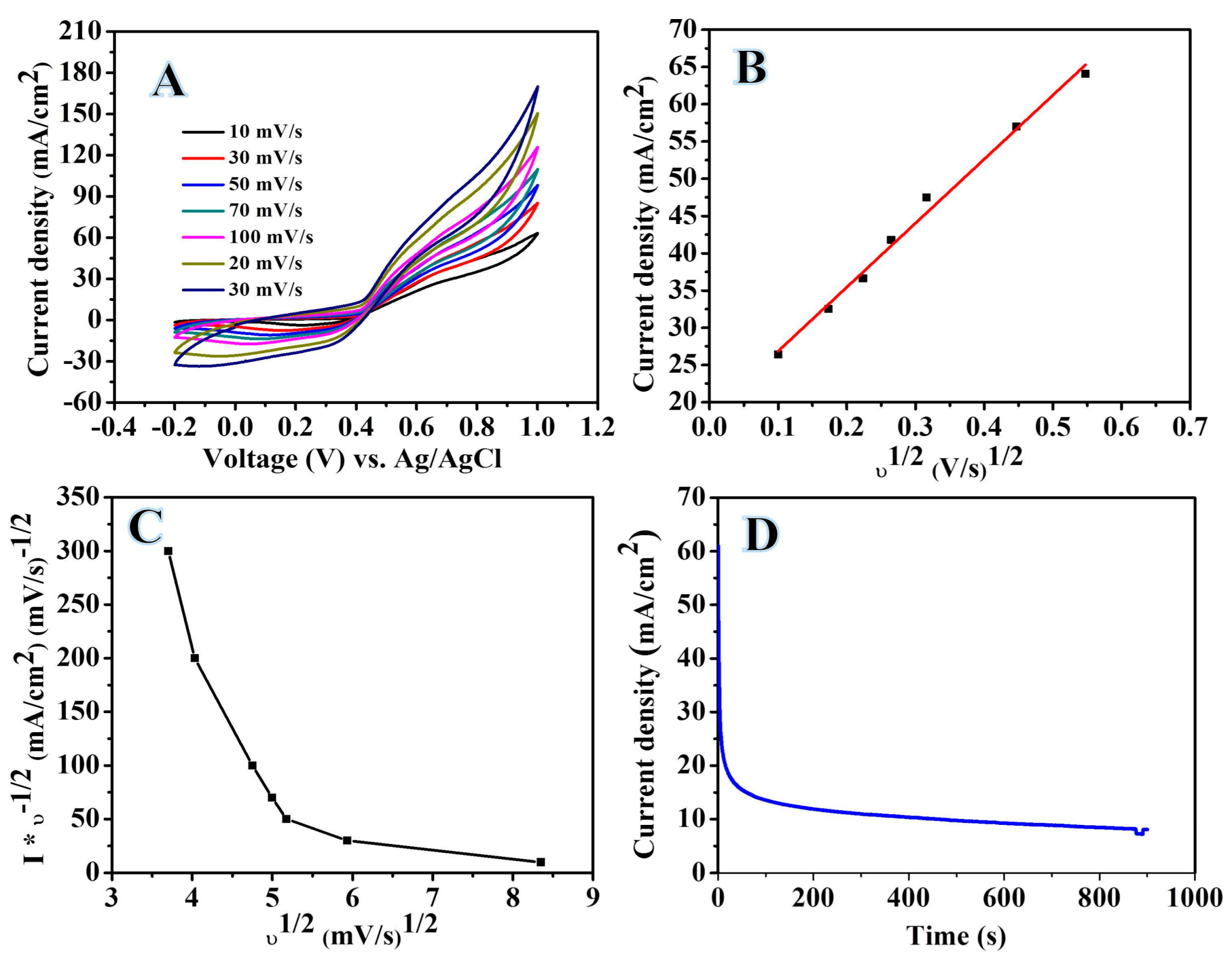
The influence of scan rates (10, 30, 50, 100, 200, and 300 mV/s) on the electrocatalytic activity of Cu3.8Ni NPs-anchored carbon electrocatalyst for UO in (1 M urea + 1 M KOH) solution is studied as shown in Figure 10A. Anodic and cathodic currents were enhanced with increasing scan rates. A linear relationship is obtained by plotting the square root of the scan rate as a function of the CD of the UO peak in Figure 10B. UO reaction is predicted to be a diffusion-governing operation. Furthermore, the variation in the scan rate is normalized current with the scan rate in Figure 10C shows a characteristic curve for an irreversible oxidation process. Accordingly, the presence of EC (electrochemical-chemical) mechanisms is proposed [42]. The diffusion coefficient of urea molecules at the electrocatalyst surface can be determined from the following equation [6,43]:
Ip = 0.4958 × 10⁻³ nFCurea (αnF/RT)0.5 D0.5 v0.5
D is the diffusion coefficient of urea, v is the scan rate, α is the anodic transfer coefficient, n is the number of transferred electrons, Curea is urea concentrations, and F is Faraday’s constant. According to the literature survey, n (2.8) was used to denote ethanol, which is more similar in chemical composition to urea than methanol and α value is 0.1 [6,43]. From a linear analysis of the relationship between Ip at the anodic peak and v0.5, the diffusion coefficient is calculated as 6.04 × 10⁻³ cm2/s.
The long-term stability of our fabricated NFs was examined via chronoamperometry with a potential value of 600 mV (Ag/AgCl) for 900 s as shown in Figure 10D. The introduced electrocatalyst underwent current decay and then reached a steady state. This decrease in the current can be attributed to the consumption of urea from solution. Additionally, the performance of electrodes was not affected due to the use of introduced catalysts supporting their enhanced stability.
3. Materials and Methods
Poly(vinyl alcohol) (PVA) (MW = 85000 − 124000 g/mol) was purchased from DC Chemical Co., Seoul, South Korea. Copper(II) acetate monohydrate (CuAc·H2O, 98%) and nickel(II) acetate tetrahydrate (NiAc·4H2O, 98%) were purchased from Sigma Aldrich, Seoul, South Korea. Deionized water (DI) was used as a solvent.
To fabricate electrospun NFs, PVA electrospinning polymeric solution was constructed by dissolving 10 wt% of PVA into DI water. The solution was then stirred until a clear solution was obtained. Then 0.2 g of copper(II) acetate monohydrate and 0.8 g of nickel(II) acetate tetrahydrate were dissolved in 5 g of DI water. The prepared metal precursor solution was then added to a glass bottle with 15 g of PVA polymeric solution. The mixture was stirred for 6 h at 60 °C and then cooled at room temperature.
The prepared sol-gel solution was electrospun using a lab scale electrospinning machine at a high voltage of 18 kV using a DC power supply and maintaining a distance of 18 cm. Fabricated NFs were gathered on a rotating cylinder covered with aluminum foil. The prepared NFs samples were dried under a vacuum for 1 day at 50 °C. Finally, the products were calcined under an argon atmosphere (Ar) for 5 h at 800 °C (2.3 °C/min to obtain final product).
A JEOL JSM-5900 scanning electron microscope (JEOL Ltd., Tokyo, Japan) and field-emission scanning electron microscope (FESEM, Hitachi S-7400, Tokyo, Japan) were used to study the surface morphology of the formed NFs. A Rigaku X-ray diffractometer (Rigaku Co., Tokyo, Japan) with Cu Kα (λ = 1.54056 Å) radiation over a range of 2θ angles of 10° to 80° was utilized to investigate the phase and crystallinity of the fabricated NFs. To acquire high-resolution images, the NFs were characterized using a JEOL JEM-2200FS transmission electron microscope (TEM) operated at 200 kV and equipped with EDX (JEOL Ltd., Tokyo, Japan). A thermo gravimetric analyzer (TGA, Ptris1, Perkin Elmer, Billerica, Massachusetts, USA) was used to study the thermal stability of NFs by heating the samples to 750 °C under an oxygen atmosphere.
Cyclic voltammetry and chronoamperometry experiments were conducted using autolab potentiostate ((PGSTAT101 controlled by Nova software), Metrohm Autolab Co., Kanaalweg 29-G, 3526 KM, Utrecht, Netherlands). The system includes three electrodes: a counter electrode (platinum wire), reference electrode (Ag/AgCl, saturated KCl) and working electrode (fabricated electrospun NFs). Measurements were performed using different concentrations of alkaline urea solution and the range of the sweep potential of the electrochemical cell was set from to −0.2 to 1 V (Ag/AgCl).
The working electrode was prepared by creating a slurry with 2 mg of the fabricated NFs, 20 μL of Nafion solution (5 wt%) and 400 μL of isopropanol. The slurry was then sonicated at room temperature for 30 min. Finally, 15 μL of the prepared slurry was poured onto the active area of the glassy carbon electrode, which was then dried at 80 °C for 20 min. The utilized active area of the glassy carbon electrode (the electrode has circle shape with D = 3 mm) was 0.0713 cm2. Therefore, all the obtained data was normalized to aforementioned area.
4. Conclusions
NiCu NP-decorated carbon NFs were synthesized using an electrospinning machine. Composite NFs exhibited strong catalytic activity for urea electro-oxidation as inferred from increased OCD (98 mA cm−2) and lowered onset potential values (380 mV versus (Ag/AgCl)). The reaction order of composite NF electrodes with respect to urea solution concentrations was found to be 0.51. Urea electro-oxidation reactions observed at the studied composite NFs were irreversible.
Funding
This research was funded by SABIC Company and Jazan University, grant number (Sabic 3/2018/1).
Acknowledgments
The author would like to thank SABIC Company and Jazan University for financially supporting this project.
Conflicts of Interest
The author declares no conflict of interest.
References
- Abdel Hameed, R.M.; Medany, S.S. Enhanced electrocatalytic activity of NiO nanoparticles supported on carbon planes towards urea electro-oxidation in NaOH solution. Int. J. Hydrogen Energy 2017, 42, 24117–24130. [Google Scholar] [CrossRef]
- Abdelkareem, M.A.; Al Haj, Y.; Alajami, M.; Alawadhi, H.; Barakat, N.A. Ni-Cd carbon nanofibers as an effective catalyst for urea fuel cell. J. Environ. Chem. Eng. 2018, 6, 332–337. [Google Scholar] [CrossRef]
- Wang, L.; Du, T.; Cheng, J.; Xie, X.; Yang, B.; Li, M. Enhanced activity of urea electrooxidation on nickel catalysts supported on tungsten carbides/carbon nanotubes. J. Power Sources 2015, 280, 550–554. [Google Scholar] [CrossRef]
- Yan, W.; Wang, D.; Botte, G.G. Electrochemical decomposition of urea with Ni-based catalysts. Appl. Catal. B 2012, 127, 221–226. [Google Scholar] [CrossRef]
- Yan, W.; Wang, D.; Diaz, L.A.; Botte, G.G. Nickel nanowires as effective catalysts for urea electro-oxidation. Electrochim. Acta 2014, 134, 266–271. [Google Scholar] [CrossRef]
- Barakat, N.A.; El-Newehy, M.H.; Yasin, A.S.; Ghouri, Z.K.; Al-Deyab, S.S. Ni&Mn nanoparticles-decorated carbon nanofibers as effective electrocatalyst for urea oxidation. Appl. Catal. A 2016, 510, 180–188. [Google Scholar]
- Boggs, B.K.; King, R.L.; Botte, G.G. Urea electrolysis: direct hydrogen production from urine. Chem. Commun. 2009, 4859–4861. [Google Scholar] [CrossRef] [PubMed]
- Ye, K.; Zhang, D.; Guo, F.; Cheng, K.; Wang, G.; Cao, D. Highly porous nickel@ carbon sponge as a novel type of three-dimensional anode with low cost for high catalytic performance of urea electro-oxidation in alkaline medium. J. Power Sources 2015, 283, 408–415. [Google Scholar] [CrossRef]
- Wang, D.; Yan, W.; Vijapur, S.H.; Botte, G.G. Enhanced electrocatalytic oxidation of urea based on nickel hydroxide nanoribbons. J. Power Sources 2012, 217, 498–502. [Google Scholar] [CrossRef]
- Bian, L.; Du, Q.; Luo, M.; Qu, L.; Li, M. Monodisperse nickel nanoparticles supported on multi-walls carbon nanotubes as an effective catalyst for the electro-oxidation of urea. Int. J. Hydrogen Energy 2017, 42, 25244–25250. [Google Scholar] [CrossRef]
- Alajami, M.; Yassin, M.A.; Ghouri, Z.K.; Al-Meer, S.; Barakat, N.A. Influence of bimetallic nanoparticles composition and synthesis temperature on the electrocatalytic activity of NiMn-incorporated carbon nanofibers toward urea oxidation. Int. J. Hydrogen Energy 2018, 43, 5561–5575. [Google Scholar] [CrossRef]
- Barakat, N.A.; Alajami, M.; Al Haj, Y.; Obaid, M.; Al-Meer, S. Enhanced onset potential NiMn-decorated activated carbon as effective and applicable anode in urea fuel cells. Catal. Commun. 2017, 97, 32–36. [Google Scholar] [CrossRef]
- Barakat, N.A.M.; Motlak, M.; Ghouri, Z.K.; Yasin, A.S.; El-Newehy, M.H.; Al-Deyab, S.S. Nickel nanoparticles-decorated graphene as highly effective and stable electrocatalyst for urea electrooxidation. J. Mol. Catal. A Chem. 2016, 421, 83–91. [Google Scholar] [CrossRef]
- Guo, F.; Ye, K.; Cheng, K.; Wang, G.; Cao, D. Preparation of nickel nanowire arrays electrode for urea electro-oxidation in alkaline medium. J. Power Sources 2015, 278, 562–568. [Google Scholar] [CrossRef]
- Barakat, N.A.M.; Amen, M.T.; Al-Mubaddel, F.S.; Karim, M.R.; Alrashed, M. NiSn nanoparticle-incorporated carbon nanofibers as efficient electrocatalysts for urea oxidation and working anodes in direct urea fuel cells. J. Adv. Res. 2019, 16, 43–53. [Google Scholar] [CrossRef]
- Hameed, R.A.; Tammam, R.H. Nickel oxide nanoparticles grown on mesoporous carbon as an efficient electrocatalyst for urea electro-oxidation. Int. J. Hydrogen Energy 2018, 43, 20591–20606. [Google Scholar] [CrossRef]
- Wang, G.; Ye, K.; Shao, J.; Zhang, Y.; Zhu, K.; Cheng, K.; Yan, J.; Wang, G.; Cao, D. Porous Ni2P nanoflower supported on nickel foam as an efficient three-dimensional electrode for urea electro-oxidation in alkaline medium. Int. J. Hydrogen Energy 2018, 43, 9316–9325. [Google Scholar] [CrossRef]
- Yan, W.; Wang, D.; Botte, G.G. Nickel and cobalt bimetallic hydroxide catalysts for urea electro-oxidation. Electrochim. Acta 2012, 61, 25–30. [Google Scholar] [CrossRef]
- Vedharathinam, V.; Botte, G.G. Direct evidence of the mechanism for the electro-oxidation of urea on Ni (OH) 2 catalyst in alkaline medium. Electrochim. Acta 2013, 108, 660–665. [Google Scholar] [CrossRef]
- Abutaleb, A.; Lolla, D.; Aljuhani, A.; Shin, H.U.; Rajala, J.W.; Chase, G.G. Effects of Surfactants on the Morphology and Properties of Electrospun Polyetherimide Fibers. Fibers 2017, 5, 33. [Google Scholar] [CrossRef]
- Al-Enizi, A.M.; Brooks, R.M.; El-Halwany, M.; Yousef, A.; Nafady, A.; Hameed, R.A. CoCr7C3-like nanorods embedded on carbon nanofibers as effective electrocatalyst for methanol electro-oxidation. Int. J. Hydrogen Energy 2018, 43, 9943–9953. [Google Scholar] [CrossRef]
- Lolla, D.; Lolla, M.; Abutaleb, A.; Shin, H.U.; Reneker, D.H.; Chase, G.G. Fabrication, polarization of electrospun polyvinylidene fluoride electret fibers and effect on capturing nanoscale solid aerosols. Materials 2016, 9, 671. [Google Scholar] [CrossRef]
- Shin, H.U.; Abutaleb, A.; Lolla, D.; Chase, G.G. Effect of Calcination Temperature on NO–CO Decomposition by Pd Catalyst Nanoparticles Supported on Alumina Nanofibers. Fibers 2017, 5, 22. [Google Scholar] [CrossRef]
- Yousef, A.; Akhtar, M.S.; Barakat, N.A.M.; Motlak, M.; Yang, O.B.; Kim, H.Y. Effective NiCu NPs-doped carbon nanofibers as counter electrodes for dye-sensitized solar cells. Electrochim. Acta 2013, 102, 142–148. [Google Scholar] [CrossRef]
- Yousef, A.; Barakat, N.A.M.; El-Newehy, M.; Kim, H.Y. Chemically stable electrospun NiCu nanorods@ carbon nanofibers for highly efficient dehydrogenation of ammonia borane. Int. J. Hydrogen Energy 2012, 37, 17715–17723. [Google Scholar] [CrossRef]
- Yousef, A.; Brooks, R.M.; Abdelkareem, M.A.; Khamaj, J.A.; El-Halwany, M.; Barakat, N.A.; EL-Newehy, M.H.; Kim, H.Y. Electrospun NiCu Nanoalloy Decorated on Carbon Nanofibers as Chemical Stable Electrocatalyst for Methanol Oxidation. ECS Electrochem. Lett. 2015, 4, F51–F55. [Google Scholar] [CrossRef]
- Yousef, A.; Brooks, R.M.; El-Halwany, M.M.; Abdelkareem, M.A.; Khamaj, J.A.; EL-Newehy, M.H.; Barakat, N.A.M.; Kim, H.Y. Fabrication of Electrical Conductive NiCu– Carbon Nanocomposite for Direct Ethanol Fuel Cells. Int. J. Electrochem. Sci. 2015, 10, 7025–7032. [Google Scholar]
- Yousef, A.; Brooks, R.M.; Abutaleb, A.; El-Newehy, M.H.; Al-Deyab, S.S.; Kim, H.Y. One-step synthesis of Co-TiC-carbon composite nanofibers at low temperature. Ceram. Int. 2017, 43, 15735–15742. [Google Scholar] [CrossRef]
- Yousef, A.; Brooks, R.M.; El-Halwany, M.M.; Abutaleb, A.; El-Newehy, M.H.; Al-Deyab, S.S.; Kim, H.Y. Electrospun CoCr7C3-supported C nanofibers: Effective, durable, and chemically stable catalyst for H2 gas generation from ammonia borane. Mol. Catal. 2017, 434, 32–38. [Google Scholar] [CrossRef]
- Yousef, A.; Brooks, R.M.; El-Newehy, M.H.; Al-Deyab, S.S.; Kim, H.Y. Electrospun Co-TiC nanoparticles embedded on carbon nanofibers: Active and chemically stable counter electrode for methanol fuel cells and dye-sensitized solar cells. Int. J. Hydrogen Energy 2017, 42, 10407–10415. [Google Scholar] [CrossRef]
- Barakat, N.A.; Abdelkareem, M.A.; El-Newehy, M.; Kim, H.Y. Influence of the nanofibrous morphology on the catalytic activity of NiO nanostructures: an effective impact toward methanol electrooxidation. Nanoscale Res. Lett. 2013, 8, 402. [Google Scholar] [CrossRef] [PubMed]
- Boskovic, B.O.; Stolojan, V.; Zeze, D.A.; Forrest, R.D.; Silva, S.R.P.; Haq, S. Branched carbon nanofiber network synthesis at room temperature using radio frequency supported microwave plasmas. J. Appl. Phys. 2004, 96, 3443. [Google Scholar] [CrossRef] [Green Version]
- Ud Din, I.; Shaharun, M.S.; Subbarao, D.; Naeem, A. Surface modification of carbon nanofibers by HNO3 treatment. Ceram. Int. 2016, 42, 966–970. [Google Scholar] [CrossRef]
- Rahim, M.A.; Hameed, R.A.; Khalil, M. Nickel as a catalyst for the electro-oxidation of methanol in alkaline medium. J. Power Sources 2004, 134, 160–169. [Google Scholar] [CrossRef]
- Thamer, B.M.; El-Newehy, M.H.; Barakat, N.A.M.; Abdelkareem, M.A.; Al-Deyab, S.S.; Kim, H.Y. Influence of Nitrogen doping on the Catalytic Activity of Ni-incorporated Carbon Nanofibers for Alkaline Direct Methanol Fuel Cells. Electrochim. Acta 2014, 142, 228–239. [Google Scholar] [CrossRef]
- Jafarian, M.; Moghaddam, R.; Mahjani, M.; Gobal, F. Electro-Catalytic Oxidation of Methanol on a Ni–Cu Alloy in Alkaline Medium. J. Appl. Electrochem. 2006, 36, 913–918. [Google Scholar] [CrossRef]
- Ding, R.; Li, X.; Shi, W.; Xu, Q.; Wang, L.; Jiang, H.; Yang, Z.; Liu, E. Mesoporous Ni-P nanocatalysts for alkaline urea elect oxidation. Electrochim. Acta 2016, 222, 455–462. [Google Scholar] [CrossRef]
- Abdel Hameed, R.M.; Medany, S.S. Influence of support material on the electrocatalytic activity of nickel oxide nanoparticles for urea electro-oxidation reaction. J. Colloid Interface Sci. 2018, 513, 536–548. [Google Scholar] [CrossRef]
- Periyasamy, S.; Subramanian, P.; Levi, E.; Aurbach, D.; Gedanken, A.; Schechter, A. Exceptionally Active and Stable Spinel Nickel Manganese Oxide Electrocatalysts for Urea Oxidation Reaction. Appl. Mater. Interfaces 2016, 8, 12176–12185. [Google Scholar] [CrossRef]
- Wang, D.; Yan, W.; Vijapur, S.H.; Botte, G.G. Electrochimica Acta Electrochemically reduced graphene oxide – nickel nanocomposites for urea electrolysis. Electrochim. Acta 2013, 89, 732–736. [Google Scholar] [CrossRef]
- Basumatary, P.; Konwar, D.; Yoon, Y.S. A novel NieCu/ZnO@MWCNT anode employed in urea fuel cell to attain superior performances. Electrochim. Acta 2018, 261, 78–85. [Google Scholar] [CrossRef]
- Yousef, A.; El-Newehy, M.H.; Al-Deyab, S.S.; Barakat, N.A. Facile synthesis of Ni-decorated multi-layers graphene sheets as effective anode for direct urea fuel cells. Arabian J. Chem. 2017, 10, 811–822. [Google Scholar] [CrossRef]
- Liu, J.; Ye, J.; Xu, C.; Jiang, S.P.; Tong, Y. Kinetics of ethanol electrooxidation at Pd electrodeposited on Ti. Electrochem. Commun. 2007, 9, 2334–2339. [Google Scholar] [CrossRef]
Figure 1.
SEM images of electrospun nanofiber mats after drying at 60 °C for 1 day (A) at low magnification, (B) at high magnification and (C and D) FE-SEM images of electrospun nanofiber mats after sintering at 800 °C for 5 h in an Argon atmosphere.
Figure 1.
SEM images of electrospun nanofiber mats after drying at 60 °C for 1 day (A) at low magnification, (B) at high magnification and (C and D) FE-SEM images of electrospun nanofiber mats after sintering at 800 °C for 5 h in an Argon atmosphere.

Figure 2.
Elemental EDX analysis of the produced nanofibers (NFs).
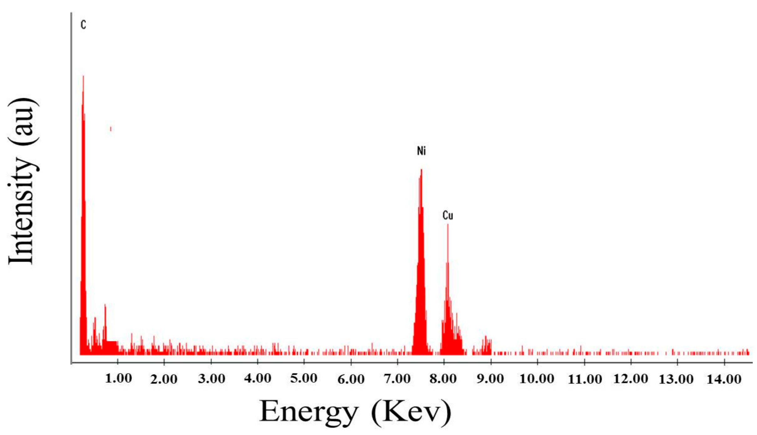
Figure 3.
(A) XRD patterns of the calcined CuAC/NiAC/PVA mat NFs after sintering at 800 °C for 5 h in an argon atmosphere, (B) TGA analysis result of CuNi/carbon nanofibers under oxygen atmosphere.
Figure 3.
(A) XRD patterns of the calcined CuAC/NiAC/PVA mat NFs after sintering at 800 °C for 5 h in an argon atmosphere, (B) TGA analysis result of CuNi/carbon nanofibers under oxygen atmosphere.
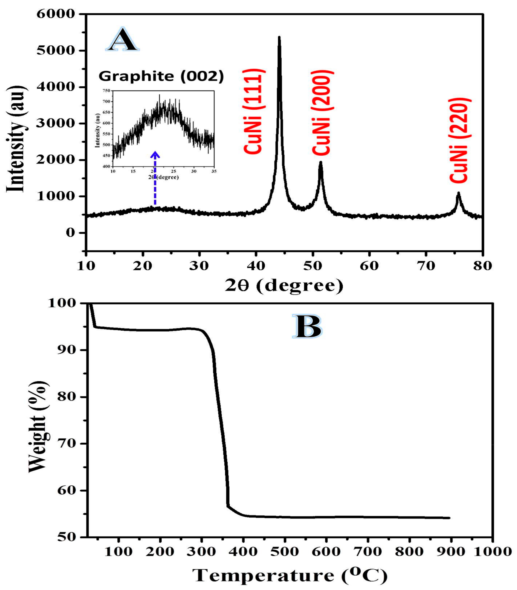
Figure 4.
Raman spectrum of the prepared nanofibers.
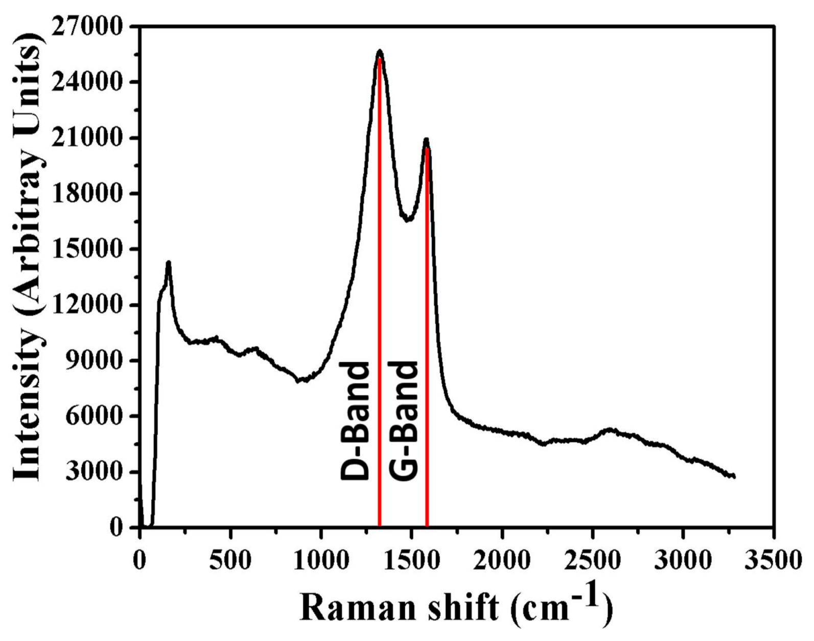
Figure 5.
(A) TEM image of a single nanofiber and (B) high resolution TEM image.

Figure 6.
STEM image for a single nanofiber along with the line EDX analysis (A) and TEM EDX results for the line in A (B).
Figure 6.
STEM image for a single nanofiber along with the line EDX analysis (A) and TEM EDX results for the line in A (B).
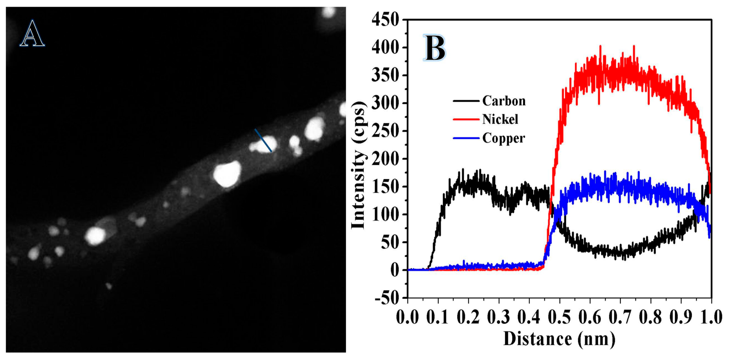
Figure 7.
Consecutive CV of NiCu-CNF electrodes in 1 M KOH solution at 50 mV/s for 30 cycles.

Figure 8.
(A) CV of NiCu-CNF electrodes in 1 M KOH solution before and after adding 1 M urea solution at 50 mV/s and (B) study the influence of glass carbon electrode, graphite, Cu NPs, and Ni-Cu CNFs on urea electroxidation (1 M urea + 1 M KOH, scan rate of 50 mV/s).
Figure 8.
(A) CV of NiCu-CNF electrodes in 1 M KOH solution before and after adding 1 M urea solution at 50 mV/s and (B) study the influence of glass carbon electrode, graphite, Cu NPs, and Ni-Cu CNFs on urea electroxidation (1 M urea + 1 M KOH, scan rate of 50 mV/s).
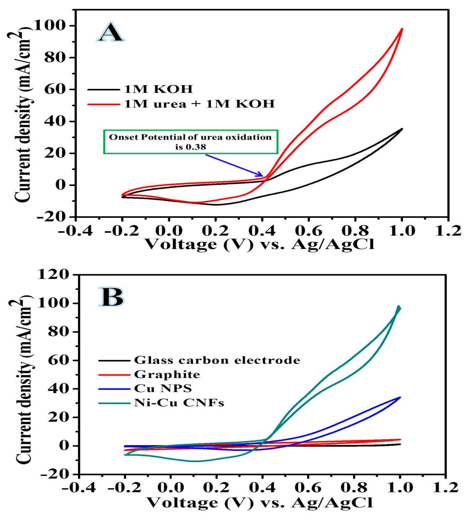
Figure 9.
(A) Cyclic voltammograms of UO in composite NF anodes in 1 M KOH solution for 50 mV/s containing different concentrations of urea. (B) Double logarithmic variations of CD of UO with urea concentrations.
Figure 9.
(A) Cyclic voltammograms of UO in composite NF anodes in 1 M KOH solution for 50 mV/s containing different concentrations of urea. (B) Double logarithmic variations of CD of UO with urea concentrations.
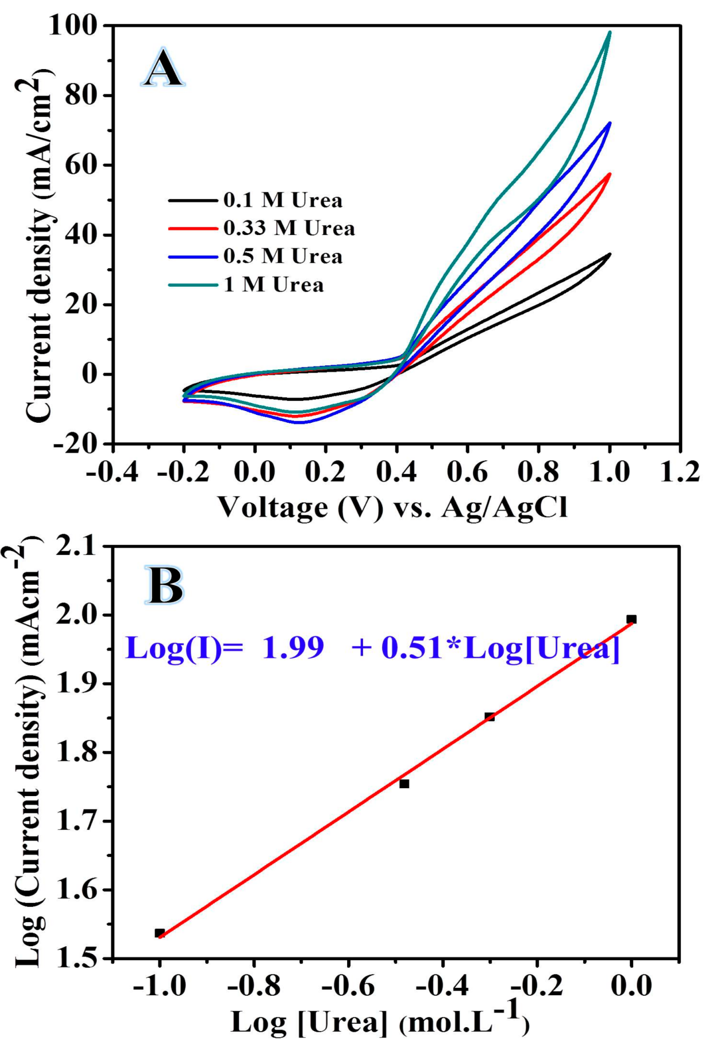
Figure 10.
(A) CV of composite NF electrodes in 1 M KOH aqueous solution after adding 1 M of urea at different scan rate values (10, 30, 50, 70, 100, 200, and 300 mV/s). (B) Variations in the square root of the scan rate as a function of the CD of UO at composite NF electrodes. (C) The scan rate normalized current density plotted against the scan rate. (D) Chronoamperogram of composite NF electrodes in 1 M KOH aqueous solution containing 1 M of urea solution at 600 mV (Ag/AgCl) for 900 s.

Table 1.
CD values of different electrocatalysts.
| Electrocatalyst | Onset Potential | CD (mA/cm2) | Anodic Peak Potential (V) | Reference Electrode | Urea Concentration (M) in KOH (M) | Reference |
|---|---|---|---|---|---|---|
| Ni | 0.39 | 22 | 0.5 | Hg/HgO | 0.33 in 1 | [4] |
| Ni-Zn-Co | 0.35 | 24 | 0.5 | Hg/HgO | 0.33 in 1 | |
| Ni-P | 1.37 | ~40 | 1.5 | RHE | 0.33 in 1 | [37] |
| NiO/Gt | 0.345 | 17 | 0.62 | Ag/AgCl | 0.33 in 0.5M NaOH | [38] |
| NiO/Gt-15 | 0.345 | 17 | 0.64 | Ag/AgCl | [1] | |
| Ni1.5Mn1.5O4 | 0.29 | 6.9 | 0.5 | Ag/AgCl | 0.33 in 1 | [39] |
| Ni-ERGO | 0.4 | 35 | Hg/HgO | 0.33 in 1 | [40] | |
| NiCo(OH)2 | 0.25 | ~20 | ~0.42 | Hg/HgO | 0.33 in 1 | [18] |
| Ni-Cu/ZnO@MWCNT | ~30 | 32 | ~0.45 | Ag/AgCl | 0.07 in 0.4 | [41] |
| NiMn-CNFs | 0.29 | 67 | 0.58 | Ag/AgCl | 2 in 1 | [6] |
| Ni-Cu-CNFs | 0.38 | 25 | 0.6 | Ag/AgCl | 1 in 1 | This study |
© 2019 by the author. Licensee MDPI, Basel, Switzerland. This article is an open access article distributed under the terms and conditions of the Creative Commons Attribution (CC BY) license (http://creativecommons.org/licenses/by/4.0/).
Share and Cite
MDPI and ACS Style
Abutaleb, A. Electrochemical Oxidation of Urea on NiCu Alloy Nanoparticles Decorated Carbon Nanofibers. Catalysts 2019, 9, 397. https://doi.org/10.3390/catal9050397
AMA Style
Abutaleb A. Electrochemical Oxidation of Urea on NiCu Alloy Nanoparticles Decorated Carbon Nanofibers. Catalysts. 2019; 9(5):397. https://doi.org/10.3390/catal9050397
Chicago/Turabian StyleAbutaleb, Ahmed. 2019. "Electrochemical Oxidation of Urea on NiCu Alloy Nanoparticles Decorated Carbon Nanofibers" Catalysts 9, no. 5: 397. https://doi.org/10.3390/catal9050397
Note that from the first issue of 2016, this journal uses article numbers instead of page numbers. See further details here.