Gas Phase Photocatalytic CO2 Reduction, “A Brief Overview for Benchmarking”

 , , , ,
Abstract
:
1. Introduction
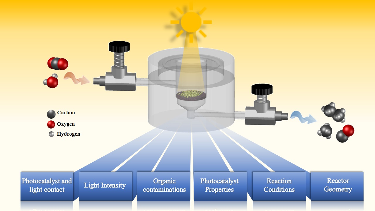
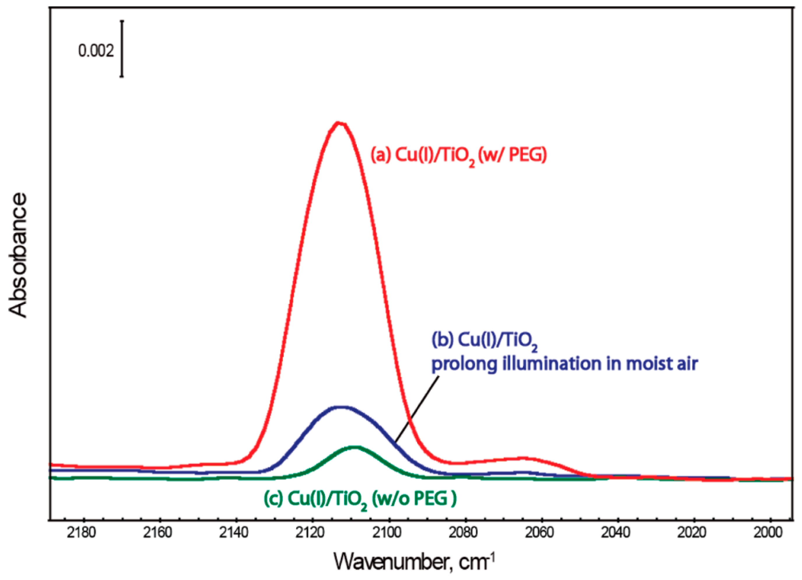
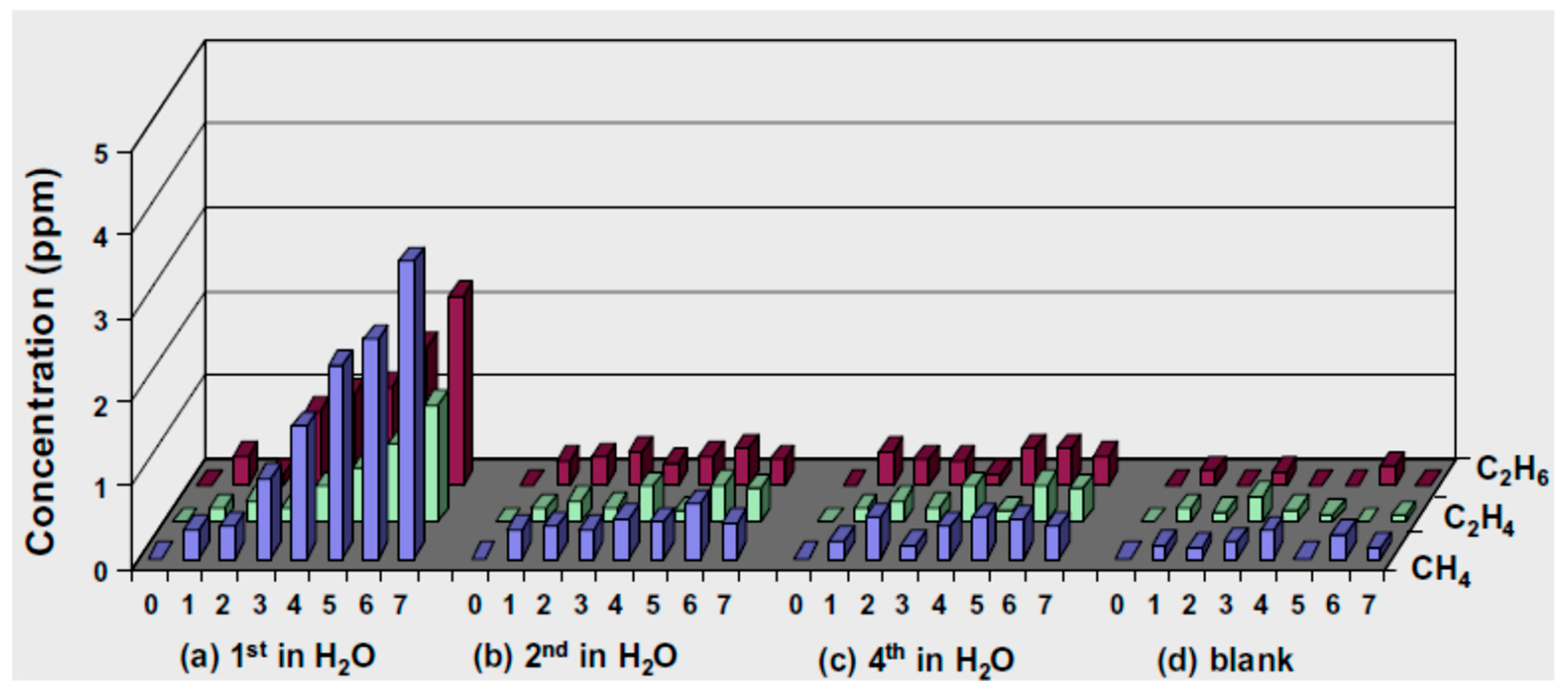
2. Role of Organic Contaminations
3. Flow versus Batch Reactors
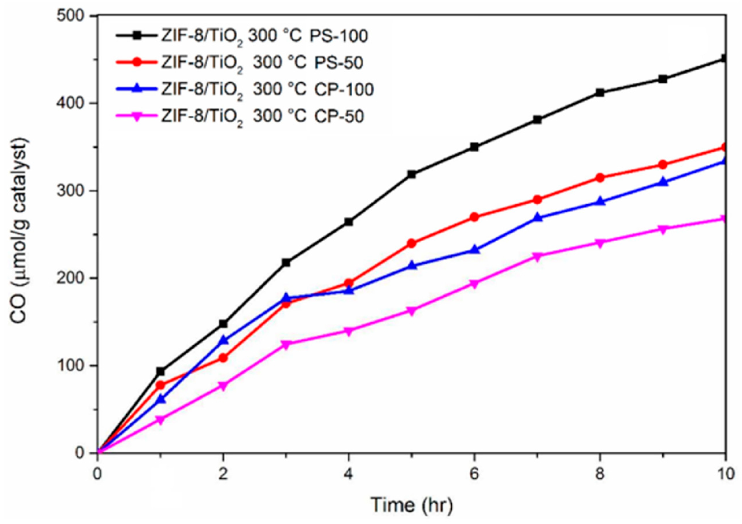
4. Reactor Geometry and Catalyst Support
4.1. Monolith Reactor
4.2. Fiber Optic Reactor
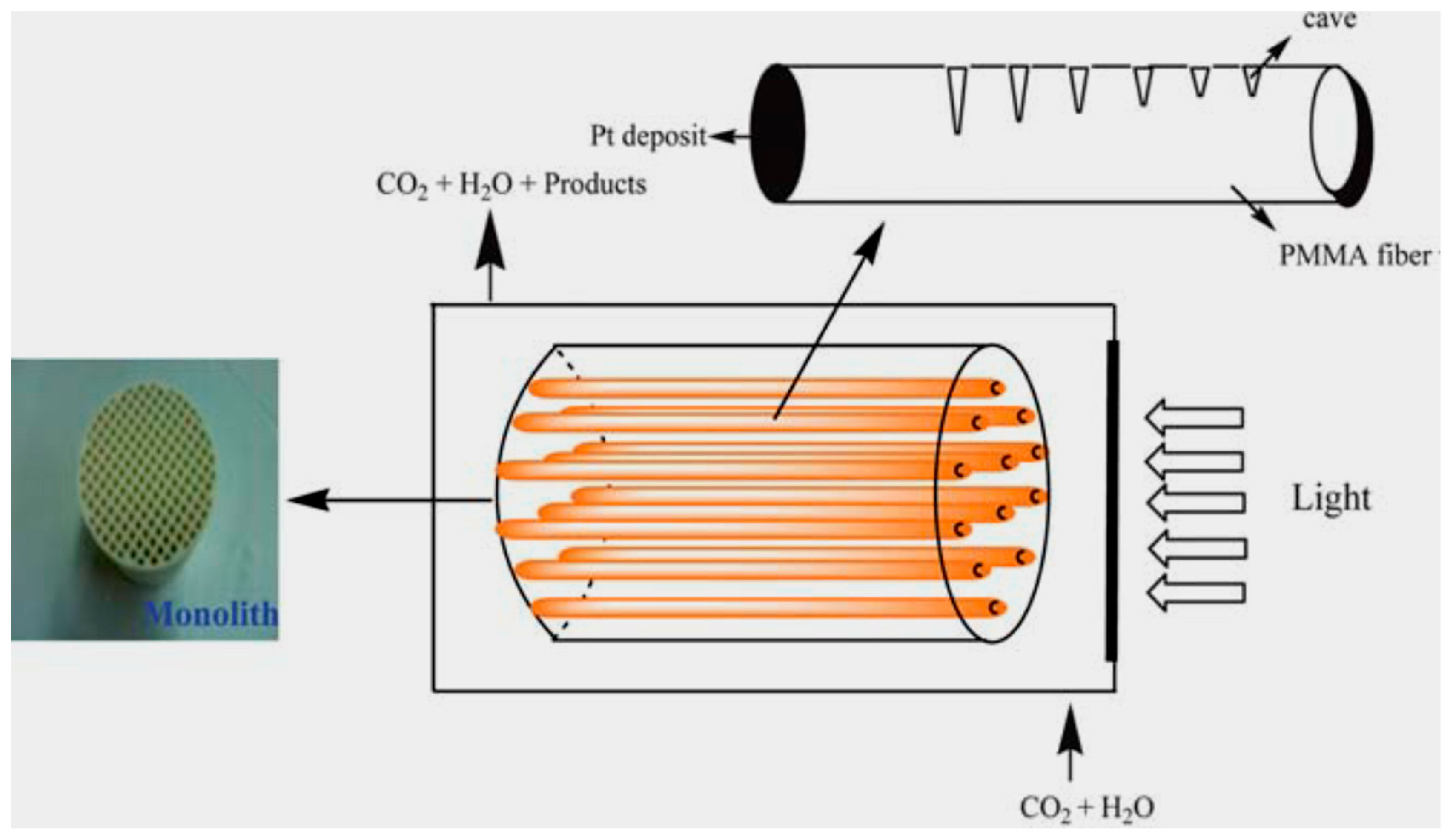
4.3. Monolith Fiber Optic Combined Reactor
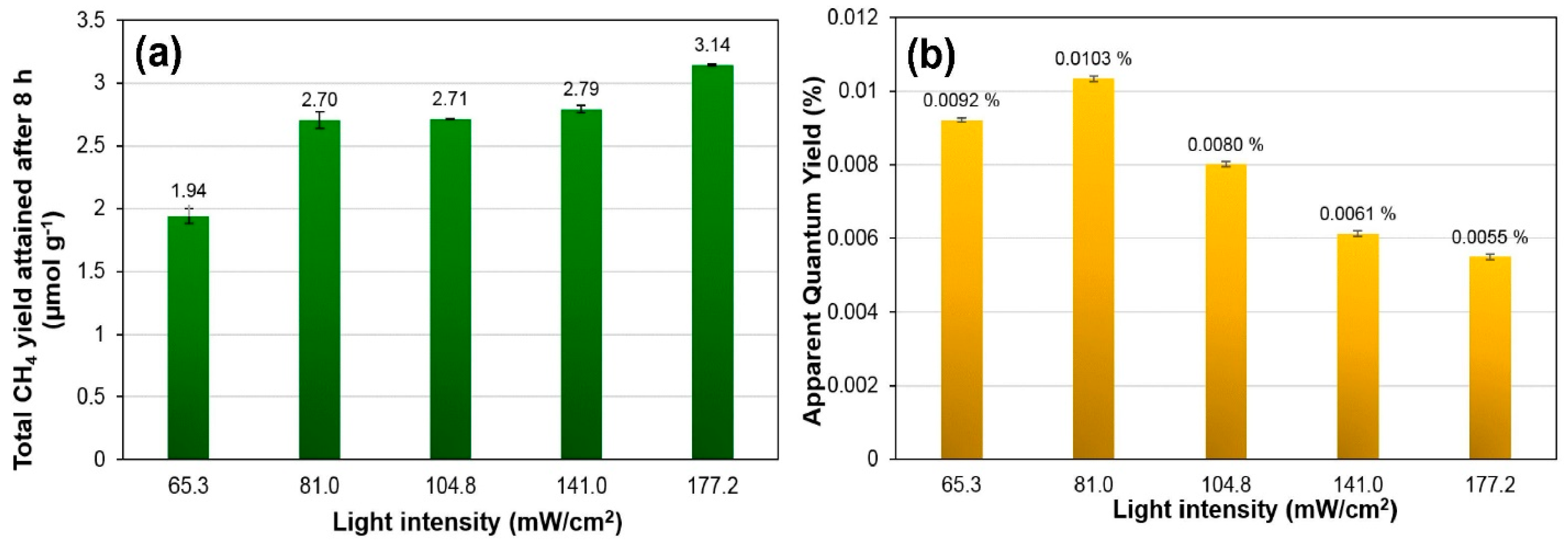
5. Light Irradiations
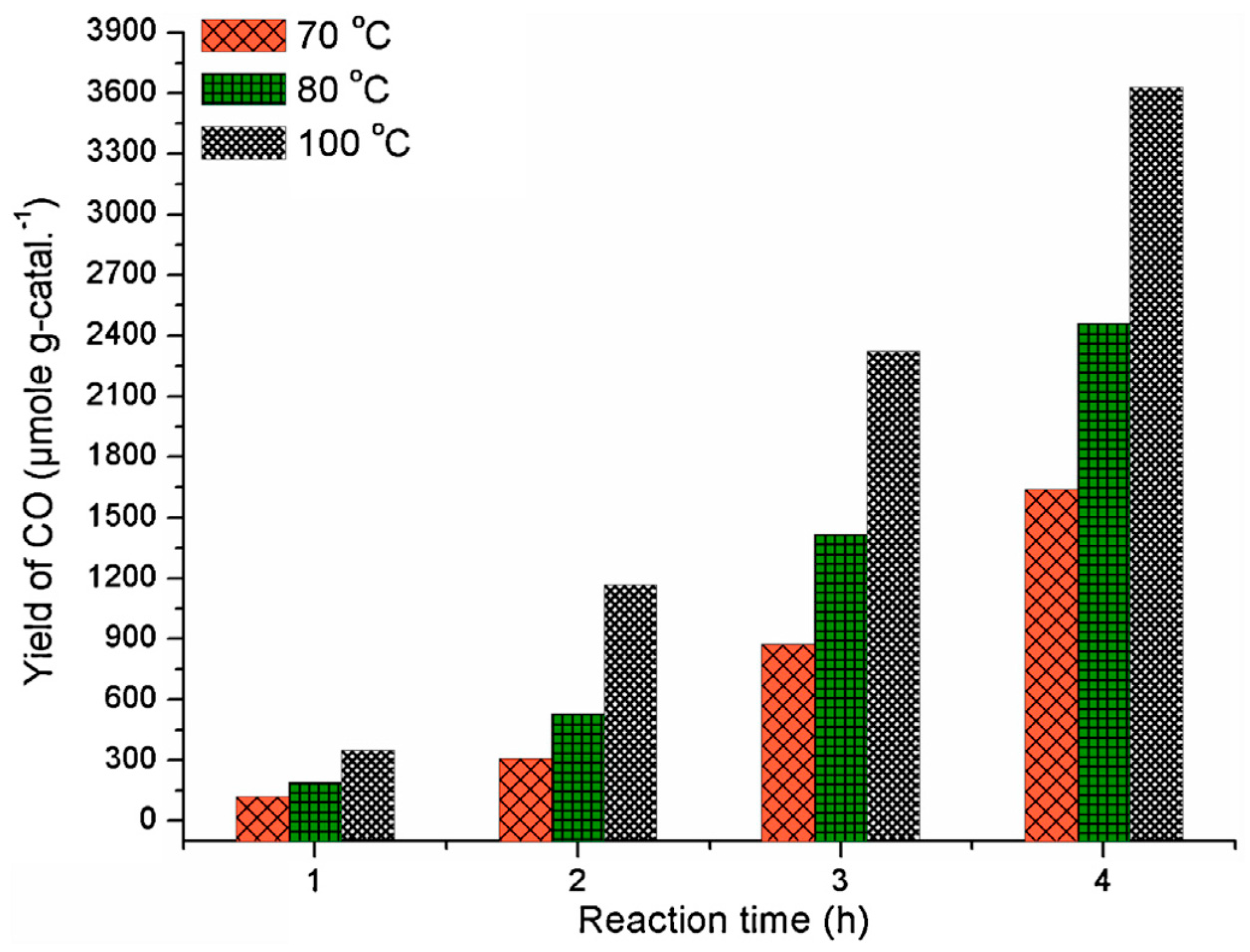
6. Temperature
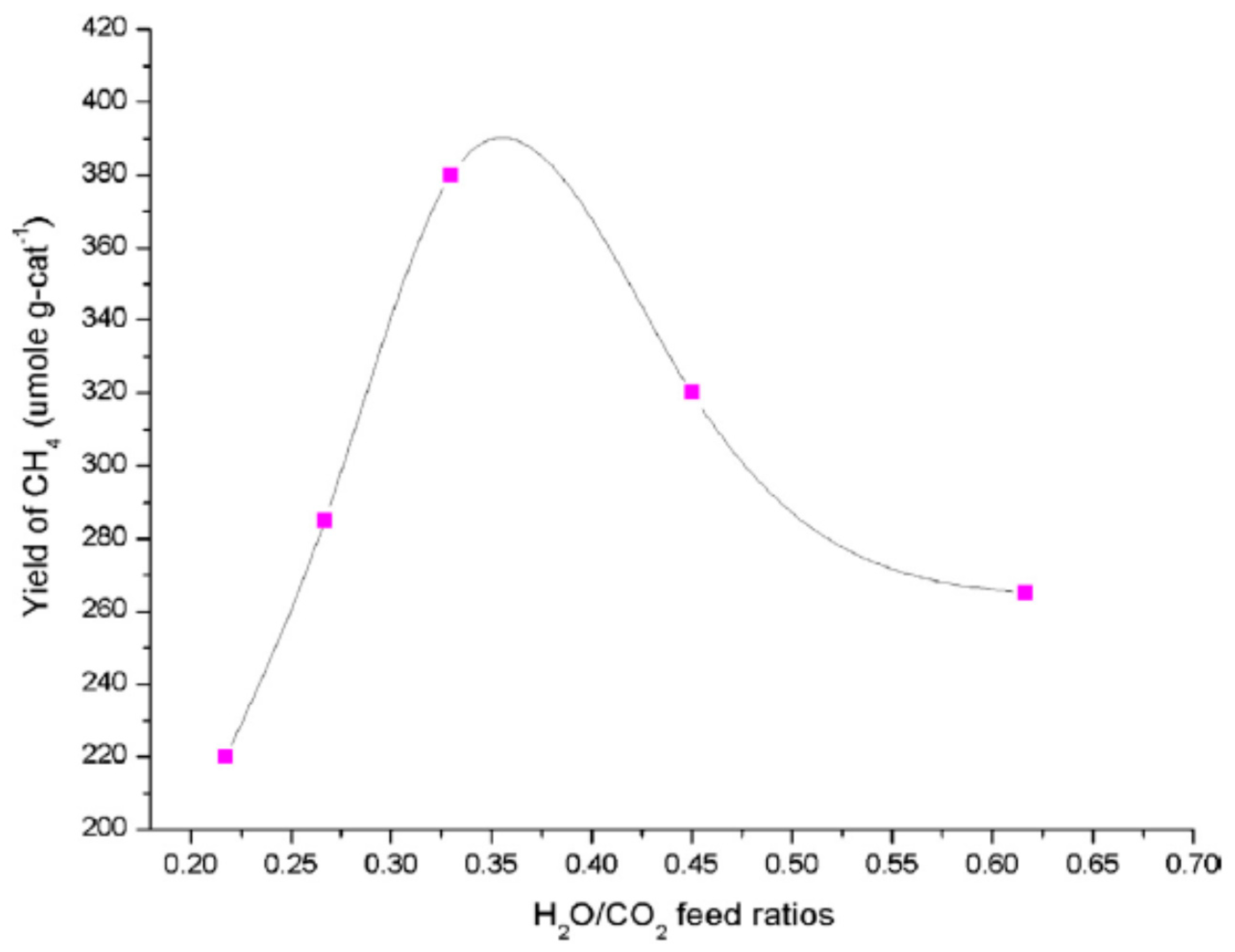
7. Effect of H2O/CO2 Feed Ratio
8. Other Factors
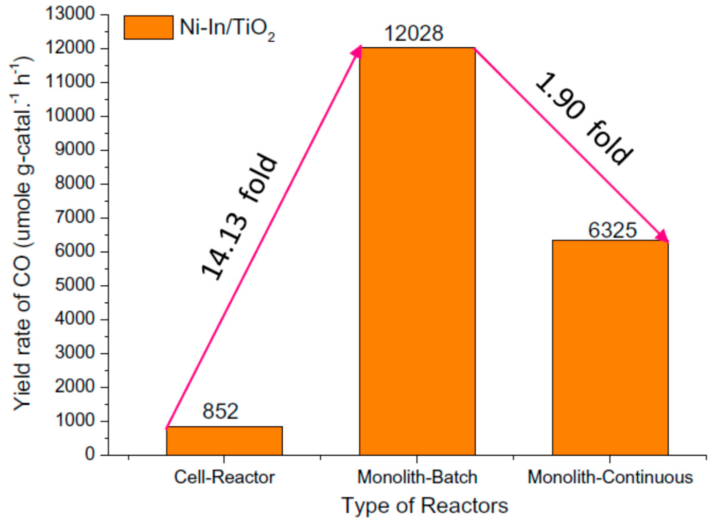
9. Benchmarking for Performance Evaluation
10. Conclusions
Supplementary Materials
Author Contributions
Funding
Conflicts of Interest
References
- Busser, G.W.; Mei, B.; Pougin, A.; Strunk, J.; Gutkowski, R.; Schuhmann, W.; Willinger, M.; Schlögl, R.; Muhler, M. Photodeposition of Copper and Chromia on Gallium Oxide: The Role of Co-Catalysts in Photocatalytic Water Splitting. ChemSusChem 2014, 7, 1030–1034. [Google Scholar] [CrossRef] [PubMed]
- Razzaq, A.; Grimes, C.A.; In, S.-I. Facile Fabrication of a Noble Metal-free Photocatalyst: TiO2 Nanotube Arrays Covered with Reduced Graphene Oxide. Carbon 2016, 98, 537–544. [Google Scholar] [CrossRef]
- Shi, R.; Chen, Y. Controlled Formation of Defective Shell on TiO2 (001) Facets for Enhanced Photocatalytic CO2 Reduction. ChemCatChem 2019, 11, 2270–2276. [Google Scholar] [CrossRef]
- Yang, C.C.; Yu, Y.H.; Van Der Linden, B.; Wu, J.C.S.; Mul, G. Artificial Photosynthesis over Crystalline TiO2-Based Catalysts: Fact or Fiction? J. Am. Chem. Soc. 2010, 132, 8398–8406. [Google Scholar] [CrossRef] [PubMed]
- Yang, C.C.; Vernimmen, J.; Meynen, V.; Cool, P.; Mul, G. Mechanistic Study of Hydrocarbon Formation in Photocatalytic CO2 Reduction over Ti-SBA-15. J. Catal. 2011, 284, 1–8. [Google Scholar] [CrossRef]
- Tahir, M.; Amin, N.S. Photocatalytic CO2 Reduction and Kinetic Study Over In/TiO2 Nanoparticles Supported Microchannel Monolith Photoreactor. Appl. Catal. A Gen. 2013, 467, 483–496. [Google Scholar] [CrossRef]
- Delavari, S.; Amin, N.A.S. Photocatalytic Conversion of CO2 And CH4 Over Immobilized Titania Nanoparticles Coated on Mesh: Optimization and Kinetic Study. Appl. Energy 2016, 162, 1171–1185. [Google Scholar] [CrossRef]
- Sorcar, S.; Thompson, J.; Hwang, Y.; Park, Y.H.; Majima, T.; Grimes, C.A.; Durrant, J.R.; In, S.-I. High-Rate Solar-Light Photoconversion of CO2 to Fuel: Controllable Transformation from C1 to C2 Products. Energy Environ. Sci. 2018, 11, 3183–3193. [Google Scholar] [CrossRef]
- Dilla, M.; Schlögl, R.; Strunk, J. Photocatalytic CO2 Reduction under Continuous Flow High-Purity Conditions: Quantitative Evaluation of CH4 Formation in the Steady-State. ChemCatChem 2017, 9, 696–704. [Google Scholar] [CrossRef]
- Kondratenko, E.V.; Mul, G.; Baltrusaitis, J.; Larrazábal, G.O.; Pérez-Ramírez, J. Status and Perspectives of CO2 Conversion into Fuels and Chemicals by Catalytic, Photocatalytic and Electrocatalytic Processes. Energy Environ. Sci. 2013, 6, 3112–3135. [Google Scholar] [CrossRef]
- Sorcar, S.; Hwang, Y.; Grimes, C.A.; In, S.-I. Highly Enhanced and Stable Activity of Defect-Induced Titania Nanoparticles for Solar Light-Driven CO2 Reduction into CH4. Mater. Today 2017, 20, 507–515. [Google Scholar] [CrossRef]
- Li, Y.; Wang, W.N.; Zhan, Z.; Woo, M.H.; Wu, C.Y.; Biswas, P. Photocatalytic Reduction of CO2 with H2O on Mesoporous Silica Supported Cu/Tio2 Catalysts. Appl. Catal. B Environ. 2010, 100, 386–392. [Google Scholar] [CrossRef]
- Zubair, M.; Kim, H.; Razzaq, A.; Grimes, C.A.; In, S.-I. Solar Spectrum Photocatalytic Conversion of CO2 to CH4 Utilizing TiO2 Nanotube Arrays Embedded with Graphene Quantum Dots. J. CO2 Util. 2018, 26, 70–79. [Google Scholar] [CrossRef]
- Zubair, M.; Razzaq, A.; Grimes, C.A.; In, S.-I. Cu2ZnSnS4 (CZTS)-ZnO: A Noble Metal-Free Hybrid Z-Scheme Photocatalyst For Enhanced Solar-Spectrum Photocatalytic Conversion of CO2 To CH4. J. CO2 Util. 2017, 20, 301–311. [Google Scholar] [CrossRef]
- Razzaq, A.; Sinhamahapatra, A.; Kang, T.H.; Grimes, C.A.; Yu, J.S.; In, S.-I. Efficient Solar Light Photoreduction of CO2 to Hydrocarbon Fuels Via Magnesiothermally Reduced TiO2 Photocatalyst. Appl. Catal. B Environ. 2017, 215, 28–35. [Google Scholar] [CrossRef]
- Kim, H.R.; Razzaq, A.; Grimes, C.A.; In, S.-I. Heterojunction pnp Cu2O/S-TiO2/CuO: Synthesis and Application to Photocatalytic Conversion of CO2 to Methane. J. CO2 Util. 2017, 20, 91–96. [Google Scholar] [CrossRef]
- Parayil, S.K.; Razzaq, A.; In, S.-I. Formation of Titania-Silica Mixed Oxides in Solvent Mixtures and Their Influences for the Photocatalytic CO2 Conversion to Hydrocarbon. J. Nanosci. Nanotechnol. 2015, 15, 7285–7292. [Google Scholar] [CrossRef] [PubMed]
- In, S.-I.; Nielsen, M.G.; Vesborg, P.C.K.; Hou, Y.; Abrams, B.L.; Henriksen, T.R.; Hansen, O.; Chorkendorff, I. Photocatalytic methane decomposition over vertically aligned transparent TiO2 nanotube arrays. Chem. Commun. 2011, 47, 2613–2615. [Google Scholar] [CrossRef] [PubMed]
- Pipelzadeh, E.; Rudolph, V.; Hanson, G.; Noble, C.; Wang, L. Applied Catalysis B: Environmental Photoreduction of CO2 on ZIF-8/TiO2 nanocomposites in a gaseous photoreactor under pressure swing. Appl. Catal. B Environ. 2017, 218, 672–678. [Google Scholar] [CrossRef]
- Adachi, K.; Ohta, K.; Mizuno, T. Photocatalytic reduction of carbon dioxide to hydrocarbon using copper-loaded titanium dioxide. Sol. Energy 1994, 53, 187–190. [Google Scholar] [CrossRef]
- Teraoka, Y.; Incorporated, F.; Suminoeku, N. Photocatalytic Reduction of CO2 with H2O on TiO2 And Cu/TiO2 Catalysts. Res. Chem. Intermed. 1994, 20, 815–823. [Google Scholar]
- Xiong, Z.; Kuang, C.C.; Lin, K.Y.; Lei, Z.; Chen, X.; Gong, B.; Yang, J.; Zhao, Y.; Zhang, J.; Xia, B.; et al. Enhanced CO2 photocatalytic reduction through simultaneously accelerated H2 evolution and CO2 hydrogenation in a twin photoreactor. J. CO2 Util. 2018, 24, 500–508. [Google Scholar] [CrossRef]
- Kim, H.R.; Razzaq, A.; Heo, H.J.; In, S.-I. Photocatalytic conversion of CO2 into hydrocarbon fuels with standard titania (Degussa P25) using newly installed experimental setup. Rapid Commun. Photosci. 2014, 2, 64–66. [Google Scholar] [CrossRef]
- Kim, K.; Razzaq, A.; Sorcar, S.; Park, Y.; Grimes, C.A.; In, S.-I. Hybrid mesoporous Cu2ZnSnS4 (CZTS)–TiO2 photocatalyst for efficient photocatalytic conversion of CO2 into CH4 under solar irradiation. RSC Adv. 2016, 6, 38964–38971. [Google Scholar] [CrossRef]
- Park, S.M.; Razzaq, A.; Park, Y.H.; Sorcar, S.; Park, Y.; Grimes, C.A.; In, S.-I. Hybrid CuxO-TiO2 Heterostructured Composites for Photocatalytic CO2 Reduction into Methane Using Solar Irradiation: Sunlight into Fuel. ACS Omega 2016, 1, 868–875. [Google Scholar] [CrossRef]
- Parayil, S.K.; Razzaq, A.; Park, S.M.; Kim, H.R.; Grimes, C.A.; In, S.-I. Photocatalytic conversion of CO2 to hydrocarbon fuel using carbon and nitrogen co-doped sodium titanate nanotubes. Appl. Catal. A Gen. 2015, 498, 205–213. [Google Scholar] [CrossRef]
- Sorcar, S.; Hwang, Y.; Lee, J.; Kim, H.; Grimes, K.M.; Grimes, C.A.; Jung, J.-W.; Cho, C.-H.; Majima, T.; Hoffmann, M.R.; et al. CO2, Water, And Sunlight to Hydrocarbon Fuels: A Sustained Sunlight to Fuel (Joule-to-Joule) Photoconversion Efficiency of 1%. Energy Environ. Sci. 2019. [Google Scholar] [CrossRef]
- Kočí, K.; Reli, M.; Kozák, O.; Lacný, Z.; Plachá, D.; Praus, P.; Obalová, L. Influence of reactor geometry on the yield of CO2 photocatalytic reduction. Catal. Today 2011, 176, 212–214. [Google Scholar] [CrossRef]
- Nguyen, T.V.; Wu, J.C.S. Photoreduction of CO2 in an optical-fiber photoreactor: Effects of metals addition and catalyst carrier. Appl. Catal. A Gen. 2008, 335, 112–120. [Google Scholar] [CrossRef]
- Tahir, M.; Amin, N.A.S. Photocatalytic reduction of carbon dioxide with water vapors over montmorillonite modified TiO2 nanocomposites. Appl. Catal. B Environ. 2013, 142–143, 512–522. [Google Scholar] [CrossRef]
- Tahir, B.; Tahir, M.; Amin, N.S. Gold–indium modified TiO2 nanocatalysts for photocatalytic CO2 reduction with H2 as reductant in a monolith photoreactor. Appl. Surf. Sci. 2015, 338, 1–14. [Google Scholar] [CrossRef]
- Tahir, M.; Tahir, B.; Amin, N.S. Photocatalytic CO2 reduction by CH4 over montmorillonite modified TiO2 nanocomposites in a continuous monolith photoreactor. Mater. Res. Bull. 2015, 63, 13–23. [Google Scholar] [CrossRef]
- Wang, W.; Ku, Y. Photocatalytic degradation of gaseous benzene in air streams by using an optical fiber photoreactor. J. Photochem. Photobiol. A Chem. 2003, 159, 47–59. [Google Scholar] [CrossRef]
- Usubharatana, P.; McMartin, D.; Veawab, A.; Tontiwachwuthikul, P. Photocatalytic process for CO2 emission reduction from industrial flue gas streams. Ind. Eng. Chem. Res. 2006, 45, 2558–2568. [Google Scholar] [CrossRef]
- Liou, P.Y.; Chen, S.C.; Wu, J.C.S.; Liu, D.; MacKintosh, S.; Maroto-Valer, M.; Linforth, R. Photocatalytic CO2 reduction using an internally illuminated monolith photoreactor. Energy Environ. Sci. 2011, 4, 1487–1494. [Google Scholar] [CrossRef]
- Wu, J.C.S.; Wu, T.-H.; Chu, T.; Huang, H.; Tsai, D. Application of optical-fiber photoreactor for CO2 photocatalytic reduction. Top. Catal. 2008, 47, 131–136. [Google Scholar] [CrossRef]
- Wang, Z.Y.; Chou, H.C.; Wu, J.C.S.; Ping Tsai, D.; Mul, G.; Engineering, C. CO2 photoreduction using NiO/InTaO4 in optical-fiber reactor for renewable energy. Appl. Catal. A Gen. 2010, 380, 172–177. [Google Scholar] [CrossRef]
- Wang, W.; Ku, Y. The light transmission and distribution in an optical fiber coated with TiO2 particles. Chemosphere 2003, 50, 999–1006. [Google Scholar] [CrossRef]
- Ola, O.; Maroto-Valer, M.; Liu, D.; MacKintosh, S.; Lee, C.W.; Wu, J.C.S. Performance comparison of CO2 conversion in slurry and monolith photoreactors using Pd and Rh-TiO2 catalyst under ultraviolet irradiation. Appl. Catal. B Environ. 2012, 126, 172–179. [Google Scholar] [CrossRef]
- Camera-Roda, G.; Santarelli, F.; Martin, C.A. Design of photocatalytic reactors made easy by considering the photons as immaterial reactants. Sol. Energy 2005, 79, 343–352. [Google Scholar] [CrossRef]
- Paulino, P.N.; Salim, V.M.M.; Resende, N.S. Zn-Cu promoted TiO2 photocatalyst for CO2 reduction with H2O under UV light. Appl. Catal. B Environ. 2016, 185, 362–370. [Google Scholar] [CrossRef]
- Han, S.; Chen, Y.; Abanades, S.; Zhang, Z. Improving photoreduction of CO2 with water to CH4 in a novel concentrated solar reactor. J. Energy Chem. 2017, 26, 743–749. [Google Scholar] [CrossRef]
- Singh, V.; Beltran, I.J.C.; Ribot, J.C.; Nagpal, P. Photocatalysis deconstructed: Design of a new selective catalyst for artificial photosynthesis. Nano Lett. 2014, 14, 597–603. [Google Scholar] [CrossRef] [PubMed]
- Li, D.; Chen, Y.; Abanades, S.; Zhang, Z. Enhanced activity of TiO2 by concentrating light for photoreduction of CO2 with H2O to CH4. Catal. Commun. 2018, 113, 6–9. [Google Scholar] [CrossRef]
- Li, D.; Fang, X.; Liu, H.; Lu, H.; Zhang, Z. Photoreduction of CO2 to CH4 on g-C3N4: The effect of concentrating light and pretreatment. AIP Conf. Proc. 2018, 1971, 020006. [Google Scholar]
- Tan, L.-L.; Ong, W.-J.; Chai, S.-P.; Mohamed, A.R. Photocatalytic reduction of CO2 with H2O over graphene oxide-supported oxygen-rich TiO2 hybrid photocatalyst under visible light irradiation: Process and kinetic studies. Chem. Eng. J. 2017, 308, 248–255. [Google Scholar] [CrossRef]
- Guan, G.; Kida, T.; Yoshida, A. Reduction of carbon dioxide with water under concentrated sunlight using photocatalyst combined with Fe-based catalyst. Appl. Catal. B Environ. 2003, 41, 387–396. [Google Scholar] [CrossRef]
- Saladin, F.; Alxneit, I. Temperature dependence of the photochemical reduction of CO2 in the presence of H2O at the solid/gas interface of TiO2. J. Chem. Soc. Faraday Trans. 1997, 93, 4159–4163. [Google Scholar] [CrossRef]
- Tan, S.S.; Zou, L.; Hu, E. Kinetic modelling for photosynthesis of hydrogen and methane through catalytic reduction of carbon dioxide with water vapour. Catal. Today 2008, 131, 125–129. [Google Scholar] [CrossRef]
- Zhang, Q.H.; Han, W.D.; Hong, Y.J.; Yu, J.G. Photocatalytic reduction of CO2 with H2O on Pt-loaded TiO2 catalyst. Catal. Today 2009, 148, 335–340. [Google Scholar] [CrossRef]
- Yamashita, H.; Ikeue, K.; Takewaki, T.; Anpo, M. In situ XAFS studies on the effects of the hydrophobic-hydrophilic properties of Ti-Beta zeolites in the photocatalytic reduction of CO2 with H2O. Top. Catal. 2002, 18, 95–100. [Google Scholar] [CrossRef]
- Wu, J.C.S.; Lin, H.M.; Lai, C.L. Photo reduction of CO2 to methanol using optical-fiber photoreactor. Appl. Catal. A Gen. 2005, 296, 194–200. [Google Scholar] [CrossRef]
- Tahir, M.; Amin, N.A.S. Performance analysis of nanostructured NiO-In2O2/TiO2 catalyst for CO2 photoreduction with H2 in a monolith photoreactor. Chem. Eng. J. 2016, 285, 635–649. [Google Scholar] [CrossRef]
- Ali, S.; Razzaq, A.; In, S.-I. Development of graphene based photocatalysts for CO2 reduction to C1 chemicals: A brief overview. Catal. Today 2018, 335, 39–54. [Google Scholar] [CrossRef]
- Hiragond, C.; Ali, S.; Sorcar, S.; In, S.-I. Hierarchical Nanostructured Photocatalysts for CO2 Photoreduction. Catalysts 2019, 9, 370. [Google Scholar] [CrossRef]
- In, S.-I.; Vaughn, D.D.; Schaak, R.E. Hybrid CuO-TiO2−xNx Hollow Nanocubes for Photocatalytic Conversion of CO2 into Methane under Solar Irradiation. Angew. Chemie Int. Ed. 2012, 51, 3915–3918. [Google Scholar] [CrossRef]
- In, S.-I.; Orlov, A.; García, F.; Tikhov, M.; Wright, D.S.; Lambert, R.M. Efficient visible light-active N-doped TiO2 photocatalysts by a reproducible and controllable synthetic route. Chem. Commun. 2006, 4236–4238. [Google Scholar] [CrossRef] [PubMed]
- In, S.-I.; Orlov, A.; Berg, R.; García, F.; Pedrosa-Jimenez, S.; Tikhov, M.S.; Wright, D.S.; Lambert, R.M. Effective visible light-activated B-doped and B, N-codoped TiO2 photocatalysts. J. Am. Chem. Soc. 2007, 129, 13790–13791. [Google Scholar] [CrossRef]
- Cortes, M.; Hamilton, J.W.J.; Sharma, P.K.; Brown, A.; Nolan, M.; Gray, K.A.; Byrne, J.A. Formal quantum efficiencies for the photocatalytic reduction of CO2 in a gas phase batch reactor. Catal. Today 2019, 326, 75–81. [Google Scholar] [CrossRef]
- Tahir, M.; Amin, N.S. Indium-doped TiO2 nanoparticles for photocatalytic CO2 reduction with H2O vapors to CH4. Appl. Catal. B Environ. 2015, 162, 98–109. [Google Scholar] [CrossRef]
- Wang, M.; Han, Q.; Li, L.; Tang, L.; Li, H.; Zhou, Y.; Zou, Z. Construction of an all-solid-state artificial Z-scheme system consisting of Bi2WO6/Au/CdS nanostructure for photocatalytic CO2 reduction into renewable hydrocarbon fuel. Nanotechnology 2017, 28, 274002. [Google Scholar] [CrossRef] [PubMed]
- Gusain, R.; Kumar, P.; Sharma, O.P.; Jain, S.L.; Khatri, O.P. Reduced graphene oxide–CuO nanocomposites for photocatalytic conversion of CO2 into methanol under visible light irradiation. Appl. Catal. B Environ. 2016, 181, 352–362. [Google Scholar] [CrossRef]
- Kozlova, E.A.; Lyulyukin, M.N.; Markovskaya, D.V.; Selishchev, D.S.; Cherepanova, S.V.; Kozlov, D.V. Synthesis of Cd1−xZnxS photocatalysts for gas-phase CO2 reduction under visible light. Photochem. Photobiol. Sci. 2019, 18, 871–877. [Google Scholar] [CrossRef] [PubMed]
- Yan, S.; Ouyang, S.; Xu, H.; Zhao, M.; Zhang, X.; Ye, J. Co-ZIF-9/TiO2 nanostructure for superior CO2 photoreduction activity. J. Mater. Chem. A 2016, 4, 15126–15133. [Google Scholar] [CrossRef]
- Li, X.; Zhuang, Z.; Li, W.; Pan, H. Photocatalytic reduction of CO2 over noble metal-loaded and nitrogen-doped mesoporous TiO2. Appl. Catal. A Gen. 2012, 429, 31–38. [Google Scholar] [CrossRef]
- Cao, S.-W.; Liu, X.-F.; Yuan, Y.-P.; Zhang, Z.-Y.; Liao, Y.-S.; Fang, J.; Loo, S.C.J.; Sum, T.C.; Xue, C. Solar-to-fuels conversion over In2O3/g-C3N4 hybrid photocatalysts. Appl. Catal. B Environ. 2014, 147, 940–946. [Google Scholar] [CrossRef]
- Hong, J.; Zhang, W.; Wang, Y.; Zhou, T.; Xu, R. Photocatalytic Reduction of Carbon Dioxide over Self-Assembled Carbon Nitride and Layered Double Hydroxide: The Role of Carbon Dioxide Enrichment. ChemCatChem 2014, 6, 2315–2321. [Google Scholar] [CrossRef]
- Li, Y.; Wang, C.; Song, M.; Li, D.; Zhang, X.; Liu, Y. TiO2−x/CoOx photocatalyst sparkles in photothermocatalytic reduction of CO2 with H2O steam. Appl. Catal. B Environ. 2019, 243, 760–770. [Google Scholar] [CrossRef]
- Tahir, M.; Tahir, B.; Amin, N.A.S. Synergistic effect in plasmonic Au/Ag alloy NPs co-coated TiO2 NWs toward visible-light enhanced CO2 photoreduction to fuels. Appl. Catal. B Environ. 2017, 204, 548–560. [Google Scholar] [CrossRef]
- Pan, B.; Luo, S.; Su, W.; Wang, X. Photocatalytic CO2 reduction with H2O over LaPO4 nanorods deposited with Pt cocatalyst. Appl. Catal. B Environ. 2015, 168, 458–464. [Google Scholar] [CrossRef]
- Zhang, N.; Ouyang, S.; Li, P.; Zhang, Y.; Xi, G.; Kako, T.; Ye, J. Ion-exchange synthesis of a micro/mesoporous Zn2GeO4 photocatalyst at room temperature for photoreduction of CO2. Chem. Commun. 2011, 47, 2041–2043. [Google Scholar] [CrossRef] [PubMed]
- Jiao, X.; Chen, Z.; Li, X.; Sun, Y.; Gao, S.; Yan, W.; Wang, C.; Zhang, Q.; Lin, Y.; Luo, Y. Defect-mediated electron–hole separation in one-unit-cell ZnIn2S4 layers for boosted solar-driven CO2 reduction. J. Am. Chem. Soc. 2017, 139, 7586–7594. [Google Scholar] [CrossRef] [PubMed]
- An, X.; Li, K.; Tang, J. Cu2O/reduced graphene oxide composites for the photocatalytic conversion of CO2. ChemSusChem 2014, 7, 1086–1093. [Google Scholar] [CrossRef] [PubMed]
- Chong, R.; Su, C.; Du, Y.; Fan, Y.; Ling, Z.; Chang, Z.; Li, D. Insights into the role of MgAl layered double oxides interlayer in Pt/TiO2 toward photocatalytic CO2 reduction. J. Catal. 2018, 363, 92–101. [Google Scholar] [CrossRef]
- Yang, Y.; Wu, J.; Xiao, T.; Tang, Z.; Shen, J.; Li, H.; Zhou, Y.; Zou, Z. Urchin-like Hierarchical CoZnAl-LDH/RGO/g-C3N4 Hybrid as a Z-Scheme Photocatalyst for Efficient and Selective CO2 Reduction. Appl. Catal. B Environ. 2019, 255, 117771. [Google Scholar] [CrossRef]
- Shi, W.; Guo, X.; Cui, C.; Jiang, K.; Li, Z.; Qu, L.; Wang, J.-C. Controllable synthesis of Cu2O decorated WO3 nanosheets with dominant (001) facets for photocatalytic CO2 reduction under visible-light irradiation. Appl. Catal. B Environ. 2019, 243, 236–242. [Google Scholar] [CrossRef]
- Fang, B.; Bonakdarpour, A.; Reilly, K.; Xing, Y.; Taghipour, F.; Wilkinson, D.P. Large-scale synthesis of TiO2 microspheres with hierarchical nanostructure for highly efficient photodriven reduction of CO2 to CH4. ACS Appl. Mater. Interfaces 2014, 6, 15488–15498. [Google Scholar] [CrossRef] [PubMed]
- Yu, J.; Jin, J.; Cheng, B.; Jaroniec, M. A noble metal-free reduced graphene oxide–CdS nanorod composite for the enhanced visible-light photocatalytic reduction of CO2 to solar fuel. J. Mater. Chem. A 2014, 2, 3407–3416. [Google Scholar] [CrossRef]
- Wang, S.; Xu, M.; Peng, T.; Zhang, C.; Li, T.; Hussain, I.; Wang, J.; Tan, B. Porous hypercrosslinked polymer-TiO2-graphene composite photocatalysts for visible-light-driven CO2 conversion. Nat. Commun. 2019, 10, 676. [Google Scholar] [CrossRef]
- Li, Q.; Lin, F.; Liu, F.; Wang, X. A CO2 photo-reduction heterogeneous cobalt-based cocatalyst by in-situ electrostatic adsorption deposition. Chem. Commun. 2019, 55, 3903–3906. [Google Scholar] [CrossRef]
- Fang, B.; Xing, Y.; Bonakdarpour, A.; Zhang, S.; Wilkinson, D.P. Hierarchical CuO–TiO2 hollow microspheres for highly efficient photodriven reduction of CO2 to CH4. ACS Sustain. Chem. Eng. 2015, 3, 2381–2388. [Google Scholar] [CrossRef]
- Long, R.; Li, Y.; Liu, Y.; Chen, S.; Zheng, X.; Gao, C.; He, C.; Chen, N.; Qi, Z.; Song, L. Isolation of Cu atoms in Pd lattice: Forming highly selective sites for photocatalytic conversion of CO2 to CH4. J. Am. Chem. Soc. 2017, 139, 4486–4492. [Google Scholar] [CrossRef] [PubMed]
- Tahir, M. Hierarchical 3D VO2/ZnV2O4 microspheres as an excellent visible light photocatalyst for CO2 reduction to solar fuels. Appl. Surf. Sci. 2019, 467, 1170–1180. [Google Scholar] [CrossRef]
- Xu, F.; Meng, K.; Cheng, B.; Yu, J.; Ho, W. Enhanced Photocatalytic Activity and Selectivity for CO2 Reduction over a TiO2 Nanofibre Mat Using Ag and MgO as Bi-Cocatalyst. ChemCatChem 2019, 11, 465–472. [Google Scholar] [CrossRef]
- Ye, L.; Wang, H.; Jin, X.; Su, Y.; Wang, D.; Xie, H.; Liu, X.; Liu, X. Synthesis of olive-green few-layered BiOI for efficient photoreduction of CO2 into solar fuels under visible/near-infrared light. Sol. Energy Mater. Sol. Cells 2016, 144, 732–739. [Google Scholar] [CrossRef]
- Jin, J.; Yu, J.; Guo, D.; Cui, C.; Ho, W. A Hierarchical Z-Scheme CdS–WO3 Photocatalyst with Enhanced CO2 Reduction Activity. Small 2015, 11, 5262–5271. [Google Scholar] [CrossRef] [PubMed]
- Hou, T.; Luo, N.; Cui, Y.-T.; Lu, J.; Li, L.; MacArthur, K.E.; Heggen, M.; Chen, R.; Fan, F.; Tian, W. Selective reduction of CO2 to CO under visible light by controlling coordination structures of CeOx-S/ZnIn2S4 hybrid catalysts. Appl. Catal. B Environ. 2019, 245, 262–270. [Google Scholar] [CrossRef]
- Lin, L.-Y.; Nie, Y.; Kavadiya, S.; Soundappan, T.; Biswas, P. N-doped reduced graphene oxide promoted nano TiO2 as a bifunctional adsorbent/photocatalyst for CO2 photoreduction: Effect of N species. Chem. Eng. J. 2017, 316, 449–460. [Google Scholar] [CrossRef]
- Reñones, P.; Moya, A.; Fresno, F.; Collado, L.; Vilatela, J.J.; Víctor, A. Hierarchical TiO2 nanofibres as photocatalyst for CO2 reduction: Influence of morphology and phase composition on catalytic activity. J. CO2 Util. 2016, 15, 24–31. [Google Scholar] [CrossRef]
- Shown, I.; Hsu, H.-C.; Chang, Y.-C.; Lin, C.-H.; Roy, P.K.; Ganguly, A.; Wang, C.-H.; Chang, J.-K.; Wu, C.-I.; Chen, L.-C. Highly efficient visible light photocatalytic reduction of CO2 to hydrocarbon fuels by Cu-nanoparticle decorated graphene oxide. Nano Lett. 2014, 14, 6097–6103. [Google Scholar] [CrossRef]
- Xiong, Z.; Luo, Y.; Zhao, Y.; Zhang, J.; Zheng, C.; Wu, J.C.S. Synthesis, characterization and enhanced photocatalytic CO2 reduction activity of graphene supported TiO2 nanocrystals with coexposed {001} and {101} facets. Phys. Chem. Chem. Phys. 2016, 18, 13186–13195. [Google Scholar] [CrossRef] [PubMed]
- Kong, X.Y.; Lee, W.Q.; Mohamed, A.R.; Chai, S.-P. Effective Steering of Charge Flow through Synergistic Inducing Oxygen Vacancy Defects and pn Heterojunctions in 2D/2D Surface-Engineered Bi2WO6−x/BiOI Cascade: Towards Superior Photocatalytic CO2 Reduction Activity. Chem. Eng. J. 2019, 372, 1183–1193. [Google Scholar] [CrossRef]
- Xiong, Z.; Wang, H.; Xu, N.; Li, H.; Fang, B.; Zhao, Y.; Zhang, J.; Zheng, C. Photocatalytic reduction of CO2 on Pt2+–Pt0/TiO2 nanoparticles under UV/Vis light irradiation: A combination of Pt2+ doping and Pt nanoparticles deposition. Int. J. Hydrogen Energy 2015, 40, 10049–10062. [Google Scholar] [CrossRef]
- Zhao, Y.; Wei, Y.; Wu, X.; Zheng, H.; Zhao, Z.; Liu, J.; Li, J. Graphene-wrapped Pt/TiO2 photocatalysts with enhanced photogenerated charges separation and reactant adsorption for high selective photoreduction of CO2 to CH4. Appl. Catal. B Environ. 2018, 226, 360–372. [Google Scholar] [CrossRef]
- Mateo, D.; Albero, J.; García, H. Graphene supported NiO/Ni nanoparticles as efficient photocatalyst for gas phase CO2 reduction with hydrogen. Appl. Catal. B Environ. 2018, 224, 563–571. [Google Scholar] [CrossRef]
- Gangopadhyay, S.; Wang, W.-N.; Biswas, P.; Mukherjee, S.; Ramalingam, B.; An, W.-J.; Niedzwiedzki, D.M. Size and Structure Matter: Enhanced CO2 Photoreduction Efficiency by Size-Resolved Ultrafine Pt Nanoparticles on TiO2 Single Crystals. J. Am. Chem. Soc. 2012, 134, 11276–11281. [Google Scholar]


| Photocatalyst | Synthesis Method | Pre-Treatment of Reactor | Light Source | Reducing Agent | Reaction Parameters | Reactor | Main Product | AQY (%) |
|---|---|---|---|---|---|---|---|---|
| Degussa P25 standard titania [23] | store-bought | purged with high purity CO2 gas, at least five times | UVP, UVGL-58 lamp with λ = 365 nm; 1200 μW cm−2 | H2O | 50 mg catalyst on a 30 mm diam. glass disk; 15.4 cm3 reactor; CO2 flowrate @ 10 cm3 min−1; 500 μL sample gas extracted; ambient temperature and pressure; 1 h irradiation | Batch reactor | CH4 @ 0.021 µmol g−1 h−1 | 0.0021 |
| CZTS−TiO2 hybrid mesoporous [24] | hot injection and annealing | purged with CO2 gas (1000 ppm in He) and vacuum | 100 W Xe solar simulator with an AM 1.5 filter; 100 mW cm−2 | H2O | 50 mg catalyst on a 30 mm diam. glass disk; 15.4 cm3 reactor; CO2 flowrate @ 10 cm3 min−1; 500 μL sample gas extracted; ambient temperature and pressure; 1 h irradiation | Batch reactor | CH4 @ 118.75 ppm g−1 h−1 | 0.0057 |
| CZTS-ZnO nanoparticles [14] | hydrothermal treatment | three times purged with CO2 gas (1000 ppm in He) and vacuum | 100 W Xe solar simulator with an AM 1.5 filter; 100 mW cm−2 | H2O | 50 mg catalyst on a 30 mm diam. glass disk; 15.4 cm3 reactor; CO2 flowrate @ 10 cm3 min−1; 500 μL sample gas extracted every 1 h; ambient temperature and pressure; 1 h irradiation | Batch reactor | CH4 @ 0.0954 µmol g−1 h−1 | 0.0128 |
| CuxO−TiO2 mesoporous p-type/n-type heterojunction material [25] | thermal decomposition then calcination | purged with CO2 gas (1000 ppm in He) and vacuum | 100 W Xe solar simulator with an AM 1.5 filter; 100 mW cm−2 | H2O | 50 mg catalyst on a 30 mm diam. glass disk; 15.4 cm3 reactor; CO2 flowrate @ 10 cm3 min−1; 500 μL sample gas extracted; ambient temperature and pressure; 1 h irradiation | Batch reactor | CH4 @ 221.63 ppm g−1 h−1 | 0.0177 |
| Pt-x-RT nanoparticles [15] | magnesio-thermic reduction | five times purged with CO2 gas (1000 ppm in He) and vacuum | 100 W Xe solar simulator with an AM 1.5 filter; 100 mW cm−2 | H2O | 70 mg catalyst on a 30 mm diam. glass disk; 15.4 cm3 reactor; CO2 flowrate @ 10 cm3 min−1; 500 μL sample gas extracted; ambient temperature and pressure; 1 h irradiation | Batch reactor | CH4 @ 1.13 µmol g−1 h−1 | 0.1234 |
| C,N-TNT06 nanotubes [26] | alkaline hydrothermal technique then calcination | purged with CO2 gas (1000 ppm in He) and vacuum | 100 W Xe solar simulator with an AM 1.5 filter; 100 mW cm−2 | H2O | 100 mg catalyst on a 30 mm diam. glass disk; 15.4 cm3 reactor; CO2 flowrate @ 10 cm3 min−1; 500 μL sample gas extracted; ambient temperature and pressure; 1 h irradiation | Batch reactor | CH4 @ 9.75 µmol g−1 h−1 | 1.0532 |
| Pt-XG/RBT nanoparticles [8] | facile vacuum treatment and photodeposition | 1 h purging with moist CO2 gas @ 40 mL min−1 | 100 W Xe solar simulator with an AM 1.5 filter; 100 mW cm−2 | H2O | 40 mg catalyst on a 4.9 cm2 porous disk; 26.57 cm3 reactor; CO2 flowrate @ 1 mL min−1; sample gas analyzed every 30 min; ambient temperature and pressure; 7 h irradiation | Continuous flow reactor | CH4 @ 37.0 µmol g−1 h−1 (AQYCH4 = 5.248) C2H6 @ 11.0 µmol g−1 h−1 (AQYC2H6 = 2.73) | 7.978 |
| Pt-BT-X nanoparticles [11] | facile low-temperature synthesis, annealing and photodeposition | 1 h purging with moist CO2 gas @ 40 mL min−1 | 100 W Xe solar simulator with an AM 1.5 filter; 100 mW cm−2 | H2O | 40 mg catalyst on a 4.9 cm2 porous disk; 26.57 cm3 reactor; CO2 flowrate @ 1 mL min−1; sample gas analyzed every 30 min; ambient temperature and pressure; 6 h irradiation | Continuous flow reactor | CH4 @ 80.35 µmol g−1 h−1 | 12.357 |
| Cux%–Pty%–BT nanoparticles [27] | facile low-temperature synthesis, annealing and photodeposition | 1 h purging with moist CO2 gas @ 40 cc min−1 | 100 W Xe solar simulator with an AM 1.5 filter; 100 mW cm−2 | H2O | 40 mg catalyst on a 2.5 cm diam. porous disk; 26.57 cm3 reactor; CO2 flowrate @ 1 mL min−1; sample gas analyzed every 30 min; ambient temperature and pressure; 6 h irradiation | Continuous flow reactor | CH4 @ 3.0 mmol g−1 (AQYCH4 = 79.14) C2H6 @ 0.15 mmol g−1 (AQYC2H6 = 6.92) | 86 |
| Photocatalyst | Synthesis Method | Pre-Treatment of Reactor | Light Source | Reducing Agent | Reaction Parameters | Reactor | Main Product | AQY (%) |
|---|---|---|---|---|---|---|---|---|
| Bi2WO6/Au/CdS Z-scheme [61] | bath deposition method | vacuum-treated several times, and then filled with high purity CO2 gas | 300 W Xe lamp (λ > 400 nm) | 0.4 mL of DI water | 100 mg catalyst; 230 mL reactor; 1 mL sample gas; ambient pressure; 8 h irradiation | Batch reactor | CH4 @ ~0.75 µmol g−1 h−1 | 0.012 b |
| rGO-CuO hybrid structure [62] | covalent grafting | purged with nitrogen gas for 15 min then purged with CO2 for 30 min under continuous stirring | 20 W white cold LED flood light (200 < λ < 700 nm); 85 W m−2 | mixture of DMF (45 mL) and H2O (5 mL) | 100 mg catalyst; 100 mL reactor; 20 μL total sample gas analyzed; 24 h irradiation | Batch reactor | CH3OH @ 1282 µmol g−1 | 0.013 b,c |
| Cd1−xZnxS solid solution [63] | two-step self-templated synthesis | purged with argon for 1 h, then 2 mL of deionized water was injected, and purged with ultra-pure CO2 for 30 min | 100 W LED plate with collimating lens; visible light (λ = 450 nm); 285 mW cm−2 | 2 mL of DI water | 45 mg catalyst; 130 cm3 reactor; 250 μL sample gas extracted every 1 h; 1 atm; 25 °C; 5 h irradiation | Batch reactor | CO @ 2.90 µmol g−1 h−1 (AQYCO = 0.016) CH4 @ 0.22 µmol g−1 h−1 (AQYCH4 = 0.005) | 0.02 a |
| Co-ZIF-9/TiO2 nanostructure [64] | in situ growth method | purged with high-purity CO2 gas | 300 W Xe lamp (200 < λ < 900 nm); 494 mW cm−2 | 3 mL DI water | 50 mg catalyst; 390 mL reactor; 0.5 mL sample gas extracted; 70 kPa; 10 h irradiation | Batch reactor with gas circulation system | CO @ 17.58 µmol g−1 h−1 | 0.053 a |
| Pt/TiO2 mesoporous structure [65] | soft-template method | purged with high purity CO2 bubbled through DI water for more than 1 h | 350 W Xe-lamp with 420 nm cutoff filter; UV light @ 34.8 mW cm−2 | H2O | 100 mg catalyst; 159 mL tubular reactor (length: 28 cm, Ø: 3 cm); 60 ± 2 °C; 2 h irradiation | Batch reactor | CH4 @ 5.7 µmol g−1 | 0.064 a |
| In2O3–C3N4 hybrid structure [66] | simple solvothermal method | purged with high-purity CO2 gas | 500 W Xenon lamp; 1200 mW cm−2 | 0.1 mL ultrapure H2O | 20 mg catalyst; 90 mL reactor; 4 h irradiation | Batch reactor | CH4 @ 159.2 ppm | 0.082 a |
| Pd/(10 wt.% LDH/C3N4) hybrid structure [67] | electrostatic interaction | introduction of 200 torr CO2 into the system | 500 W Hg (Xe) lamp without filter | 100 mL H2O | 200 mg catalyst; 200 μL sample gas extracted; AQY @ λ = 420 nm; 200 torr; 72 h irradiation | Batch reactor | CH4 @ 6.5 µmol | 0.093 b |
| In/TiO2-monolith [6] | sol–gel single step method | continuous passing of CO2, He and H2O mixture through the reactor for about 1 h | 200 W Hg lamp for UV irradiations (λ < 252 nm); 150 mW cm−2 | H2O | 50 mg catalyst; 150 cm3 reactor; 1000 μL sample gas extracted; PCO2 = 0.20 bar; PH2O = 0.074 bar; 10 h irradiation | Batch reactor | CO @ 962 µmol g−1 h−1 | 0.10 b |
| TiO2−x/CoOxhybrid structure [68] | (own method) | blown with CO2 for 20 min | 150 W UV lamp; 20 mW cm−2 | 2 mL of DI water | 50 mg catalyst; 100 mL reactor; 1.01 bar; room temperature; 4 h irradiation | Batch reactor | CO @ 1.247 µmol g−1 h−1 (AQYCO = 0.0817) CH4 @ 0.0903 µmol g−1 h−1 (AQYCH4 = 0.0237) | 0.105 a |
| Ag-Au/TiO2 nanowires [69] | facile hydrothermal synthesis | compressed CO2 and H2 were continuously passed through the reactor | 35 W HID Xe lamp; 20 mW cm−2 | H2 | 10 mg catalyst; 108 cm3 reactor; 0.20 bar; 4 h irradiation | Batch reactor | CO @ 1813 µmol g−1 h−1 | 0.1108 b |
| LaPO4–Pt nanorods [70] | hydrothermal method and photo deposition | reactor was evacuated and filled with CO2 for 1 h with stirring | 125 W high-pressure Hg lamp (λ < 365 nm) | 70 mL H2O | 50 mg catalyst; 200 mL reactor; 1 atm; 20 °C; 4 h irradiation | Batch reactor | CH4 @ 0.62 µmol g−1 | 0.15 b |
| Zn2GeO4 micro/mesoporous [71] | simple ion exchange | vacuum-pumped and washed with high purity CO2 gas | 300 W Xe arc lamp (λ = 251 ± 16 nm) | 0.5 mL DI water | 200 mg catalyst; 360 mL reactor; 0.5 mL sample gas extracted; ambient pressure; 12 h irradiation | Batch reactor | CH4 @ 9.5 ppm g−1 h−1 | 0.20 b |
| ZnIn2S4 one-unit-cell atomic layers [72] | (own method) | vacuum-treated three times, then pumped with high-purity CO2 | PLS-SXE300/ 300 UV Xe lamp; 100 mW cm−2 | 2 mL DI water | 100 mg catalyst; atmospheric pressure; 298 ± 0.2 K; 1 h irradiation | Batch reactor | CO @ 33.2 µmol g−1 h−1 | 0.23 b |
| Cu2O/x% RGO composites [73] | microwave-assisted hydrothermal reaction | CO2 purged | 150 W Xe lamp; 540 µW cm−2 | 3 mL DI water | 500 mg catalyst; 120 mL reactor; sample gas extracted every 30 min; 20 h irradiation | Batch reactor | CO @ 50 ppm g−1 h−1 | 0.34 b |
| Pt/MgAl-LDO/TiO2 hybrid structure [74] | in-situ deposition, calcination and photo deposition | degassed for 30 min, and then bubbled with CO2 till the pressure reaches 1 atm | 300 W Xe lamp; 1.1 mW cm2 | H2O | 20 mg catalyst; AQY @ λ = 365 nm; 1 atm; 20 °C; 8 h irradiation | Batch reactor | CH4 @ 0.11 µmol | 0.35 b,c |
| LDH/RGO/CN hybrid structure [75] | hydrothermal synthesis and in situ loading | vacuum-treated several times, and then flowed with high purity CO2 gas | 300 W Xe arc lamp; 1.8 mW cm−2 | 4 mL DI water | 50 mg catalyst; 420 mL reactor; 1 mL sample gas extracted; AQY @ λ = 385 nm; ambient pressure; 5 h irradiation | Batch reactor | CO @ 10.11 µmol g−1 h−1 | 0.45 b |
| Cu2O/WO3 nanosheets [76] | modified method | vacuum treated, and then purged several times with high purity CO2 gas | 300 W Xenon arc lamp with a UV cutoff filter (λ > 400 nm) | H2O | 85 mg catalyst; 18 h irradiation | Batch reactor | CO @ 0.56 µmol g−1 h−1 | 0.503 b |
| TiO2 microsphere [77] | sol−gel approach | introduction of pressurized CO2 @ (50 psi) | 40 W Hg UV lamp (λ = 254 nm); 20 mW cm−2 | 100 μL H2O | 200 mg catalyst; 39 mm diameter and 9 mm depth reactor; 10 mL sample gas extracted; 50 psi; 24 h irradiation | Batch reactor | CO @ 0.56 µmol g−1 h−1 (AQYCO = 0.204) CH4 @ 0.94 µmol g−1 h−1 (AQYCH4 = 0.34) | 0.54 b,c |
| RGO-CdS nanorod composites [78] | microwave hydrothermal route | degassed with nitrogen for 30 min | 300 W Xe arc lamp with a UV-cutoff filter (λ ≥ 420 nm); 150 mW cm−2 | 10 mL distilled water | 100 mg catalyst; 200 mL reactor; 1 mL sample gas extracted every 1 h; atmospheric pressure and ambient temperature; 3 h irradiation | Batch reactor | CH4 @ 2.51 µmol g−1 h−1 | 0.80 b |
| HCP-TiO2-FG composite [79] | in situ growth | - | 300 W Xe lamp (λ ≥ 420 nm); 433 mW cm−2 | H2O | 20 mg catalyst; standard atmospheric pressure; 5 h irradiation | Batch reactor | CH4 @ 27.62 µmol g−1 h−1 (AQYCH4 = 1.14) CO @ 21.63 µmol g−1 h−1 (AQYCO = 0.2227) | 1.36 a |
| Co/Palheterostructure [80] | in situ electrostatic adsorption deposition process | filled with high purity CO2 gas | 300 W Xe lamp | 5 mL acetonitrile/H2O (4:1) | 9 mg photosensitizer + 1 mg co-catalyst + 1 mL TEOA; 80 mL reactor; AQY @ λ = 420 nm; 1 atm; 25 °C; 6 h irradiation | Batch reactor | CO @ ~86 µmol | 1.38 b |
| CuO−TiO2 hollow microspheres [81] | one-pot template-free synthesis | introduction of pressurized CO2 @ (50 psi) | 40 W Hg UV lamp(λ = 254 nm); 20 mW cm−2 | 200 μL H2O | 10 mg catalyst; reactor diameter of 39 mm and a depth of 9 mm; 50 psi; 24 h irradiation | Batch reactor | CO @ 14.5 µmol g−1 h−1 (AQYCO = 1.285) CH4 @ 2.1 µmol g−1 h−1 (AQYCH4 = 0.747) | 2.03 b |
| Pt-TiO2 spheres [77] | microwave-assisted solvothermal method | introduction of pressurized CO2 @ (50 psi) | 40 W Hg UV lamp (λ = 254 nm); 20 mW cm−2 | 100 μL H2O | 200 mg catalyst; 39 mm diameter and 9 mm depth reactor; 10 mL sample gas extracted; 50 psi; 24 h irradiation | Batch reactor | CO @ 18.9 µmol g−1 h−1 (AQYCO = 1.632) CH4 @ 3.6 µmol g−1 h−1 (AQYCH4 = 1.315) | 2.95 b,c |
| PdxCu1-TiO2 hybrid structures [82] | in situ growth | filled with 0.2 MPa CO2 for 60 min | 300 W Xe lamp (λ < 400 nm); 2 mW cm−2 | H2O | 5 mg of TiO2 + 0.01 mmol of metal atoms for catalyst; 100 mL reactor; 0.2 MPa; 2 h irradiation | Batch reactor | CH4 @ 19.6 µmol g−1 h−1 | 12.53 a |
| In/TiO2 nanoparticles [60] | sol–gel single step method | purged with CO2 and He for an hour | 500 W mercury flash lamp (λ = 365 nm); 40 mW cm−2 | H2O | 0.25 mg catalyst; 106 cm3 reactor; 1000 μL sample gas extracted; 0.20 bars, 373 K; 8 h irradiation | Batch reactor | CH4 @ 244 µmol g−1 h−1 (AQYCH4 = 42.39) CO @ 81 µmol g−1 h−1 (AQYCO = 3.52) | 45.91 a |
| ZnV2O4 microspheres [83] | one-step hydrothermal process | purged with CO2 gas carrying H2O for 30 min | 35 W HID Xe lamp; 20 mW cm−2 | H2O | 100 mg catalyst; CO2 flowrate @ 20 mL min−1; 108 cm3 reactor; 0.20 bar; 100 °C; 4 h irradiation | Batch reactor | CO @ 485 µmol g−1 h−1 (AQYCO = 31.92) CH3OH @ 100 µmol g−1 h−1 (AQYCH3OH = 19.75) | 51.67 a |
| NiO/InTaO4 monolith coated structure [35] | impregnation method and sol-gel method | purged overnight using a flow of He then switched to pure CO2 with saturated water vapor for 1 h | 300 W Xe arc lamp with AM 1.5 filter; 100 mW cm−2 | H2O | 88.7 mg catalyst; 216 cm3 reactor; 1 bar; 70 °C; 2 h irradiation | - | CH3OH @ 0.16 µmol g−1 h−1 (AQYCH3OH = 0.012) CH3CHO @ 0.3 µmol g−1 h−1 (AQYCH3CHO = 0.058) | 0.07 b |
| MAT nanofibers [84] | (own method) | blown with nitrogen for 30 min | 300 W simulated solar Xe arc lamp | H2O | 200 mL reactor; 1 mL sample gas extracted every 1 h; atmospheric pressure and ambient temperature; 3 h irradiation | - | CH4 @ 0.86 µmol g−1 h−1 | 0.091 b |
| BiOI few-layered nanosheets [85] | (own method) | thoroughly vacuum-treated | 300 W high pressure Xe lamp | 5 mL H2SO4 & 1.712 g NaHCO3 | 150 mg catalyst; 500 mL reactor; 0.15 mL sample gas extracted; 20 °C AQY @ λ = 420 nm; 4 h irradiation | - | CO @ 0.615 µmol h−1 CH4 @ 0.063 µmol h−1 | 0.140 b |
| CdS–WO3 heterostructure [86] | simple precipitation method | blown with nitrogen for 30 min | 300 W Xe arc lamp with a UV-cutoff filter (λ ≥ 420 nm); 6.0 mW cm−2 | H2O | 100 mg catalyst +10 mL of distilled water to form films; 200 mL reactor; 1 mL sample gas extracted every 1 h; AQY @ λ = 420 nm; atmospheric pressure and ambient temperature | - | CH4 @ 1.02 µmol g−1 h−1 | 0.40 b |
| CeOx-S/ZnIn2S4 hybrid structure [87] | one-pot hydrothermal method | introduction of high purity CO2 gas into the reactor for 3 min | 9.0 W (455 nm LEDs) | 0.5 mL H2O | 10 mg catalyst; 6.98 mL reactor; 1 bar; below 42 °C; 10 h irradiation | - | CO @ 0.18 mmol g−1 h−1 | 1.34 b |
| Pt/TiO2 [42] | vacuum impregnation | reactor was cleaned with nitrogen for half an hour then it was replaced and saturated with CO2 gas for at least 30 min | 300 W UV light; 10 mW cm−2 | 2 mL H2O | 100 mL reactor; sample gas analyzed every 1 h; 0.1 MPa; 7 h irradiation | - | CH4 @ 20.55 µmol g−1 | 10.03 b |
| Photocatalyst | Synthesis Method | Pre-Treatment of Reactor | Light Source | Reducing Agent | Reaction Parameters | Reactor | Main Product | AQY (%) |
|---|---|---|---|---|---|---|---|---|
| TiO2/NRGO-300 nanocomposites [88] | one-step urea-assisted hydrothermal method | purged with CO2 at 16 mL min−1 for 40 min | 400 W Xe lamp (250 < λ < 400 nm); 11.5 mW cm−2 | H2O | 10 mg catalyst; CO2 flowrate @ 3 mL min−1; sample gas extracted every 1 h; 8 h irradiation | Continuous flow reactor | CO @ 356.5 µmol g−1 | 0.0072 b,c |
| 5GO–OTiO2 (UV light) hybrid heterostructure [46] | facile wet chemical impregnation technique | purged with wet CO2 at 30 mL min−1 for 30 min | 500 W Xe arc lamp with a UV filter (λ > 400 nm); 81.0 mW cm−2 | H2O | CO2 flowrate @ 5 mL min−1; Quartz column reactor (ID = 9 mm, OD = 11 mm, length = 250 mm); sample gas extracted every 0.5 h; 1 bar; 25 ± 5 °C; 8 h irradiation | Continuous flow reactor | CH4 @ 2.7 µmol g−1 | 0.0103 b |
| TiO2 nanofibers [89] | sol-gel method and electrospinning technique | firstly, degassed under vacuum and then purged with Ar for 1 h, then fed with CO2/H2O mixture in dark for 1 h, then reactor was pressurized and kept at a reaction flow rate of 2 mL min−1 for another 1 h. | four 6 W UV lamps (λmax = 365 nm) | H2O | 100 mg catalyst; 190 mL reactor; 7.25 CO2:H2O molar ratio; sample gas analyzed every 22 min; 2 bars; 50 °C; 20 h irradiation | Continuous flow reactor | CO @ 203.91 μmol gcat−1 | 0.04 b |
| Cu/GO-2 hybrid structure [90] | one-pot microwave process | purged with nitrogen gas for 1 h then followed by pure CO2 for another 1 h | 300 W halogen lamp; 100 mW cm−2 | H2O | 100 mg catalyst; 300 mL reactor; CO2 flowrate @ 4 µL/min; 25.0 ± 0.5 °C; 2 h irradiation | Continuous flow reactor | CH3OH @ 2.94µmol g−1 h−1 (AQYCH3OH = 0.0296) CH3CHO @ 3.88 µmol g−1 h−1 (AQYCH3CHO = 0.065) | 0.095 a |
| G/TiO2-001/101 nanocomposites [91] | one-pot solvothermal method | purged with the CO2 + H2O mixture at 200 mL min−1 for 1 h and then reduced to 5 mL min−1 for 30 min | 300W Xe arc lamp (300 < λ < 400 nm); 20.5 mW cm−2 | 5 mL DI water | 10 mg catalyst; 85 mL reactor; sample gas analyzed every 30 min; atmospheric pressure; 120 °C; 4 h irradiation | Continuous flow reactor | CO @ 70.8 µmol g−1 h−1 | 0.0864 b,c |
| BWO-OV/BiOI binanosheets [92] | simple self-assembly approach | purged with the CO2/H2O gas mixture at 50 mL min−1 for 30 min | 500 W Xenon arc lamp with UV cut-off filter (to remove λ < 400 nm) | H2O | CO2 flowrate @ 5 mL min−1; sample gas analyzed every 1 h; atmospheric pressure and ambient temperature; 8 h irradiation | Continuous flow reactor | CO @ 320.19 µmol g−1 CH4 @ 18.32 µmol g−1 | 0.432 b |
| Pt2+–Pt0/TiO2 nanoparticles [93] | sol–gel method | purged with CO2 + H2O mixture at 200 mL min−1 for 1 h and then at 3 mL min−1 for another 30 min. | 300 W Xe arc lamp UV light irradiation (320 < λ < 420 nm); 32.5 mW cm−2 | H2O | 200 mg catalyst; 85 mL reactor; sample gas extracted every 40 min; 50 °C; 7 h irradiation | Continuous flow reactor | CH4 @ 264.5 µmol g−1 (AQYCH4 = 1.35) CO (AQYCO = 0.07) | 1.42 b |
| (Pt/TiO2) @rGO core-shell-structured [94] | hydrothermal method | vacuum-treated, then purged with CO2 gas @ 50 cm3 min−1 for 30 min | 300 W Xe lamp (320 < λ < 780 nm); 80 mW cm−2 | 2.0 mL H2O | 100 mg catalyst; sample gas extracted every 1 h; 0.1 MPa; 4 °C; 8 h irradiation | Continuous flow reactor | CH4 @ 41.3 µmol g−1 h−1 | 1.93 b,c |
| NiO/Ni-GR nanoparticles [95] | pyrolysis and incipient wetness impregnation | photoreactor was heated at different temperatures | 300 W Xe lamp; 2236 W m−2 | H2 | 40 mg catalyst; 51 mL reactor; 1.3 bar; 200 °C; 2 h irradiation | Continuous flow reactor | CH4 @ 642 µmol gNi−1 h−1 | 1.98 b |
| Pt-TiO2 nanostructured films [96] | aerosol chemical vapor deposition | purged with CO2 and water vapor at 100 mL min−1 for 1 h, and then reduced and maintained at 3 mL min−1 | 400 W Xe lamp (250 < λ < 388 nm); 19.6 mW cm−2 | H2O | 0.7 mg catalyst; atmospheric pressure and room temperature; 5 h irradiation | Continuous flow reactor | CH4 @ 1361 µmol g−1 h−1 (AQYCH4 = 2.33) CO @ 179.34 µmol g−1 h−1 (AQYCO = 0.077) | 2.41 b,c |
© 2019 by the authors. Licensee MDPI, Basel, Switzerland. This article is an open access article distributed under the terms and conditions of the Creative Commons Attribution (CC BY) license (http://creativecommons.org/licenses/by/4.0/).
Share and Cite
Ali, S.; Flores, M.C.; Razzaq, A.; Sorcar, S.; Hiragond, C.B.; Kim, H.R.; Park, Y.H.; Hwang, Y.; Kim, H.S.; Kim, H.; et al. Gas Phase Photocatalytic CO2 Reduction, “A Brief Overview for Benchmarking”. Catalysts 2019, 9, 727. https://doi.org/10.3390/catal9090727
Ali S, Flores MC, Razzaq A, Sorcar S, Hiragond CB, Kim HR, Park YH, Hwang Y, Kim HS, Kim H, et al. Gas Phase Photocatalytic CO2 Reduction, “A Brief Overview for Benchmarking”. Catalysts. 2019; 9(9):727. https://doi.org/10.3390/catal9090727
Chicago/Turabian StyleAli, Shahzad, Monica Claire Flores, Abdul Razzaq, Saurav Sorcar, Chaitanya B. Hiragond, Hye Rim Kim, Young Ho Park, Yunju Hwang, Hong Soo Kim, Hwapyong Kim, and et al. 2019. "Gas Phase Photocatalytic CO2 Reduction, “A Brief Overview for Benchmarking”" Catalysts 9, no. 9: 727. https://doi.org/10.3390/catal9090727