
Development of an Actuator for Translatory Movement by Means of a Detented Switching Shaft Based on a Shape Memory Alloy Wire for Repeatable Mechanical Positioning


Abstract
:
1. Introduction
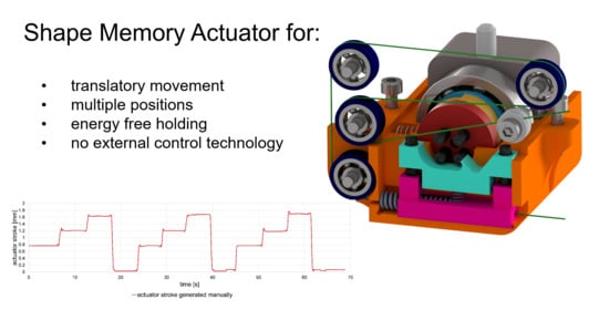
2. Requirements of the Actuator
3. Conceptual Design of the SMA-Based Actuator/Preliminary Considerations
- Actuator (with reset option);
- Gears (to increase forces, or to convert rotation into translation);
- Mechanical control of intermediate positions;
- Interface (power transmission);
- Position holder (energy free).
4. Overall System Description
5. Assembly/Prototype
6. Evaluation
7. Conclusion and Outlook
Supplementary Materials
Author Contributions
Funding
Institutional Review Board Statement
Informed Consent Statement
Data Availability Statement
Conflicts of Interest
References
- Ansari:, M.; Golzar, M.; Baghani, M.; Taghavimehr, M.; Abbasi Shirsavar, M.; Yahyavi, M. An experimental investigation on shape memory polymer and metallic stents under bending and radial compression. Eng. Res. Express 2020, 2, 45012. [Google Scholar] [CrossRef]
- Shape Memory Alloy Engineering. For Aerospace, Structural and Biomedical Applications; Butterworth-Heinemann: Oxford, UK, 2015; ISBN 978-0-08-099920-3.
- Mohd Jani, J.; Leary, M.; Subic, A.; Gibson, M.A. A review of shape memory alloy research, applications and opportunities. Mater. Des. (1980–2015) 2014, 56, 1078–1113. [Google Scholar] [CrossRef]
- Janocha, H. Adaptronics and Smart Structures. Basics, Materials, Design, and Applications; 2. Aufl.; Springer: Berlin/Heidelberg, Germany, 2007; ISBN 978-3-540-71965-6. [Google Scholar]
- Butera, F.; Miyazaki, S. Recent Development of Shape Memory Alloys and Engineering Actuator Application. Actuator 2010, 12, 206–211. [Google Scholar]
- Mertmann, M. Fatigue in Nitinol Actuators. Actuator 2006, 10, 461–466. [Google Scholar]
- Dimitris, C. Lagoudas. Shape Memory Alloys; Springer: Boston, MA, USA, 2008; ISBN 978-0-387-47684-1. [Google Scholar]
- SAES Getters Group. SmartFlex Brochure. Available online: https://www.saesgetters.com/sites/default/files/SmartFlex%20Brochure_2.pdf (accessed on 10 December 2020).
- SAES Getters Group. SmartFlex Wire & Spring Datasheet. Available online: https://www.saesgetters.com/sites/default/files/SmartFlex%20Wire%20&%20Spring%20datasheets_0.pdf (accessed on 10 December 2020).
- DYNALLOY, Inc. Technical Characteristics of Actuator Wires: FLEXINOL. Available online: https://www.dynalloy.com/pdfs/TCF1140.pdf (accessed on 10 December 2020).
- Ingpuls GmbH. Forgedächtnislegierungen. Available online: https://ingpuls.de/images/download/produktkatalog_ip_de.pdf (accessed on 10 December 2020).
- Reynaerts, D.; van Brussel, H. Design aspects of shape memory actuators. Mechatronics 1998, 8, 635–656. [Google Scholar] [CrossRef]
- Huang, W. On the selection of shape memory alloys for actuators. Mater. Des. (1980–2015) 2002, 23, 11–19. [Google Scholar] [CrossRef]
- Langbein, S.; Czechowicz, A. Konstruktionspraxis Formgedächtnistechnik; Springer Fachmedien Wiesbaden: Wiesbaden, Germany, 2013; ISBN 978-3-8348-1957-4. [Google Scholar]
- Hartl, D.J.; Lagoudas, D.C. Aerospace applications of shape memory alloys. Proc. Inst. Mech. Eng. Part G J. Aerosp. Eng. 2007, 221, 535–552. [Google Scholar] [CrossRef] [Green Version]
- Stoeckel, D. Shape memory actuators for automotive applications. Mater. Des. (1980–2015) 1990, 11, 302–307. [Google Scholar] [CrossRef]
- Fraunhofer, I.W.U. Neuartige Aktoren für Industrie, Medizintechnik und Automobilbau. Elektron. Elektromechanik 2012, November, 64–65. [Google Scholar]
- Liu, M.; Hao, L.; Zhang, W.; Zhao, Z. A novel design of shape-memory alloy-based soft robotic gripper with variable stiffness. Int. J. Adv. Robot. Syst. 2020, 17, 172988142090781. [Google Scholar] [CrossRef]
- Cruz Ulloa, C.; Terrile, S.; Barrientos, A. Soft Underwater Robot Actuated by Shape-Memory Alloys “JellyRobcib” for Path Tracking through Fuzzy Visual Control. Appl. Sci. 2020, 10, 7160. [Google Scholar] [CrossRef]
- Ashuri, T.; Armani, A.; Jalilzadeh Hamidi, R.; Reasnor, T.; Ahmadi, S.; Iqbal, K. Biomedical soft robots: Current status and perspective. Biomed. Eng. Lett. 2020, 10, 369–385. [Google Scholar] [CrossRef] [PubMed]
- Romanò, J.; Lazzari, F.; Garavaglia, L.; Pittaccio, S. Alternative design strategy and multi-material integration in the development of biologically-inspired soft robots: A proof-of-concept. Smart Mater. Struct. 2020, 29, 125016. [Google Scholar] [CrossRef]
- Copaci, D.-S.; Blanco, D.; Martin-Clemente, A.; Moreno, L. Flexible shape memory alloy actuators for soft robotics: Modelling and control. Int. J. Adv. Robot. Syst. 2020, 17, 172988141988674. [Google Scholar] [CrossRef]
- Motzki, P.; Khelfa, F.; Zimmer, L.; Schmidt, M.; Seelecke, S. Design and Validation of a Reconfigurable Robotic End-Effector Based on Shape Memory Alloys. IEEE/ASME Trans. Mechatron. 2019, 24, 293–303. [Google Scholar] [CrossRef]
- Motzki, P.; Seelecke, S.; Rizzello, G. A Shape Memory Alloy Smart Handling System for Advanced Manufacturing Applications. In Proceedings of the 2020 7th International Conference on Control, Decision and Information Technologies (CoDIT), Prague, Czech Republic, 29 June–2 July 2020; IEEE: New York, NY, USA, 2020; pp. 229–234, ISBN 978-1-7281-5953-9. [Google Scholar]
- Pagel, K. Entwicklung von Formgedächtnisaktoren mit inhärenter Führungsfunktion; Verlag Wissenschaftliche Scripten: Auerbach, Germany, 2018; ISBN 978-3-95735-094-7. [Google Scholar]
- Seelecke, S. Sensing Properties of SMA Actuators and Sensorless Control. In Shape Memory Alloy Valves; Czechowicz, A., Langbein, S., Eds.; Springer International Publishing: Cham, Switzerland, 2015; pp. 73–87. ISBN 978-3-319-19080-8. [Google Scholar]
- Elahinia, M.H. Shape Memory Alloy Actuators. Design, Fabrication, and Experimental Evaluation; Wiley: Chichester, UK, 2016; ISBN 978-1-118-35944-0. [Google Scholar]
- Schiedeck, F. Entwicklung eines Modells für Formgedächtnisaktoren im Geregelten Dynamischen Betrieb. Ph.D. Thesis, Zugl.: Hannover, Univ., PZH Produktionstechn, Zentrum, Garbsen, Germany, 2009. [Google Scholar]
- Pagel, K.; Drossel, W.-G.; Zorn, W.; Bucht, A.; Kunze, H. Adaptive Control Concept for Shape Memory Alloy Actuators. In Volume 1: Development and Characterization of Multifunctional Materials; Modeling, Simulation and Control of Adaptive Systems; Integrated System Design and Implementation, Proceedings of the ASME 2013 Conference on Smart Materials, Adaptive Structures and Intelligent Systems, Snowbird, UT, USA, 16–18 September 2013; American Society of Mechanical Engineers: New York, NY, USA, 2013; ISBN 978-0-7918-5603-1. [Google Scholar]
- Pollmann, J.; Meier, H.; Kuhlenkötter, B. Modular Desktop Machining Centre with SMA Actuation. In Small Machine Tools for Small Workpieces; Wulfsberg, J.P., Sanders, A., Eds.; Springer International Publishing: Cham, Switzerland, 2017; pp. 117–130. ISBN 978-3-319-49267-4. [Google Scholar]
- Manfredi, L.; Cuschieri, A. Design of a 2 DOFs Mini Hollow Joint Actuated with SMA Wires. Materials (Basel) 2018, 11, 2014. [Google Scholar] [CrossRef] [PubMed] [Green Version]
- Manfredi, L.; Huan, Y.; Cuschieri, A. Low power consumption mini rotary actuator with SMA wires. Smart Mater. Struct. 2017, 26, 115003. [Google Scholar] [CrossRef]
- Duering, T.W.; Pelton, A.R. TiNi Shape Memory Alloys. Adv. Mater. 1994, 1035–1048. [Google Scholar]
- Eggeler, G.; Hornbogen, E.; Yawny, A.; Heckmann, A.; Wagner, M. Structural and functional fatigue of NiTi shape memory alloys. Mater. Sci. Eng. A 2004, 378, 24–33. [Google Scholar] [CrossRef]
- Theren, B.; Otibar, D.; Weirich, A.; Brandenburg, J.; Kuhlenkötter, B. Methodology for Minimizing Operational Influences of the Test Rig During Long-Term Investigations of SMA Wires. In Proceedings of the ASME 2019 Conference on Smart Materials, Adaptive Structures and Intelligent Systems, Louisville, KY, USA, 9–11 September 2019; American Society of Mechanical Engineers: New York, NY, USA, 2019. ISBN 978-0-7918-5913-1. [Google Scholar]
- Hornbogen; Schmitt. Legierungen mit Formgedächtnis; VS Verlag für Sozialwissenschaften: Opladen, Germany, 1991; ISBN 3531083880. [Google Scholar]
- Fleczok, B.; Rathmann, C.; Otibar, D.; Weirich, A.; Kuhlenkötter, B. Impact of Different Electrical Time-Based Activations on NiTi Shape Memory Alloys. IOP Conf. Ser. Mater. Sci. Eng. 2017, 216, 12008. [Google Scholar] [CrossRef] [Green Version]
- Feldhusen, J.; Grote, K.-H. Pahl/Beitz Konstruktionslehre; Springer: Berlin/Heidelberg, Germany, 2013; ISBN 978-3-642-29568-3. [Google Scholar]
- Roddeck, W. Einführung in die Mechatronik, 6; überarb. u. erw. Auflage 2020; Springer Fachmedien Wiesbaden GmbH: Wiesbaden, Germany, 2019; ISBN 978-3-658-27774-1. [Google Scholar]


| Nr. | Requirements | D/R | Numerical Value (incl. Tolerance) | Unit | ||
|---|---|---|---|---|---|---|
| min. | exact | max. | ||||
| 1 | Characteristics of the Actuator | |||||
| 1.1 | actuating power | D | unknown | N | ||
| 1.2 | stroke | D | 1 | variable | 3 | mm |
| 1.3 | wire actuation frequency | D | 3 | Hz | ||
| 1.4 | number of intermediate position | D | ||||
| 1.5 | small installation space | D | ||||
| 1.6 | low weight | D | ||||
| 1.7 | position retainer | D | mechanic/energy free | |||
| 1.8 | repeat accuracy | D | −0.1 | 0.1 | mm | |
| 1.9 | not antagonistic | R | ||||
| 1.10 | translational movement | D | ||||
| 1.11 | wire length | D | 300 | mm | ||
| 1.12 | voltage | D | 12 | V | ||
| 1.13 | interface | D | ||||
| 1.14 | automatically resetting | D | ||||
| 1.15 | fast activation | D | 2 | s | ||
| 1.16 | position accuracy | D | −0.1 | 0.1 | mm | |
| 1.17 | long lifespan | R | ||||
| 1.18 | low maintenance costs | R | ||||
| 1.19 | no digital control technology | D | ||||
| 2 | Environmental Conditions | |||||
| 2.1 | temperature resistance | D | −10 | 60 | °C | |
| 2.2 | low cross-sensitivity | D | ||||
| 4 | Analysis of the System to Be Developed | |
| 4.1 | What or which subsystem should primary be improved? | None. It is a new development. |
| 4.2 | Of which elements (function carriers) does the subsystem to be optimized consist? | Actuator (SMA element and reset), gearbox, interface, position holder. |
| 4.3 | What is the most important function of the technical system to be developed? | Mechanical control of intermediate positions, targeted positioning. |
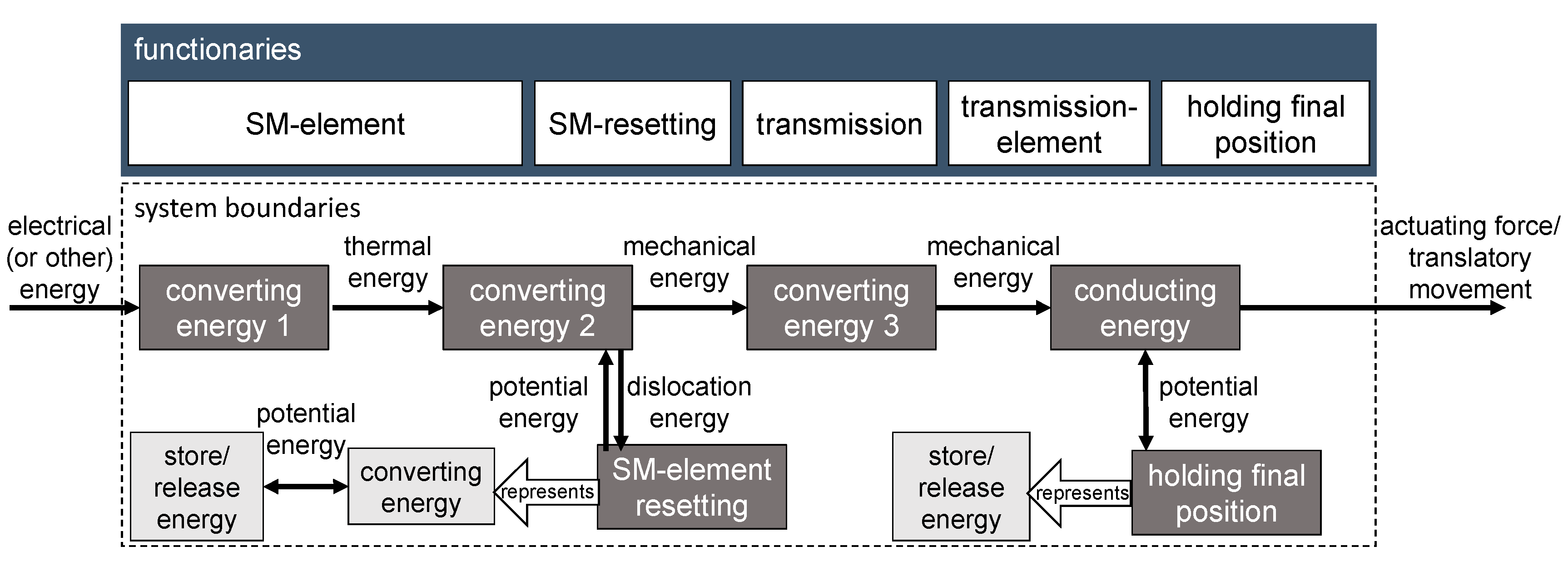
| 4.4 | What functions are provided by the individual system components? (functional structure) | See Figure 1. |
| 5 | Analysis of the Problem Solution | |
| 5.1 | What is the ideal result to strive for? | The actuator is adjustable in steps of a few mm in its setting range and every intermediate position can hold energy free. |
| 5.2 | Are there any known solutions similar to the ideal result or were developed based on an analogous problem? | No. |
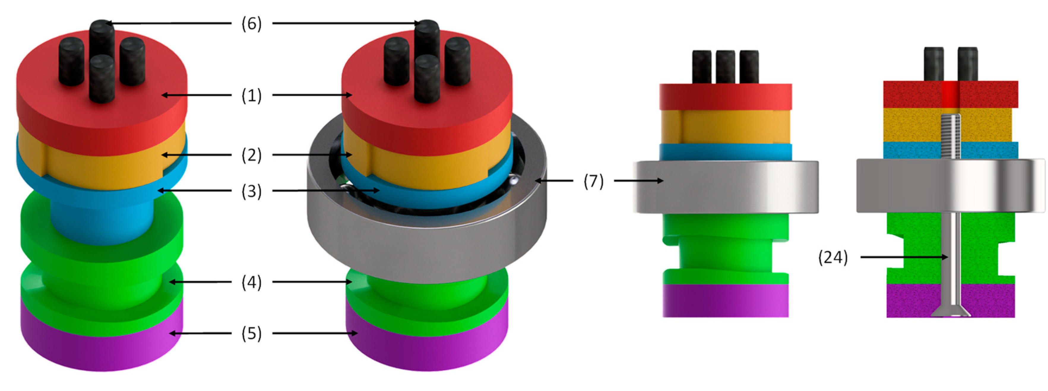
| Nr. | Name | Color |
|---|---|---|
| 1 | cover plate | red |
| 2 | ratchet plate | orange (light) |
| 3 | bearing plate | blue (light) |
| 4 | guide groove plate | green (light) |
| 5 | end plate | purple |
| 6 | switch pin (ISO 8734–3 × 14) | black |
| 7 | bearing (big) (SKF 6001-2Z) | silver |
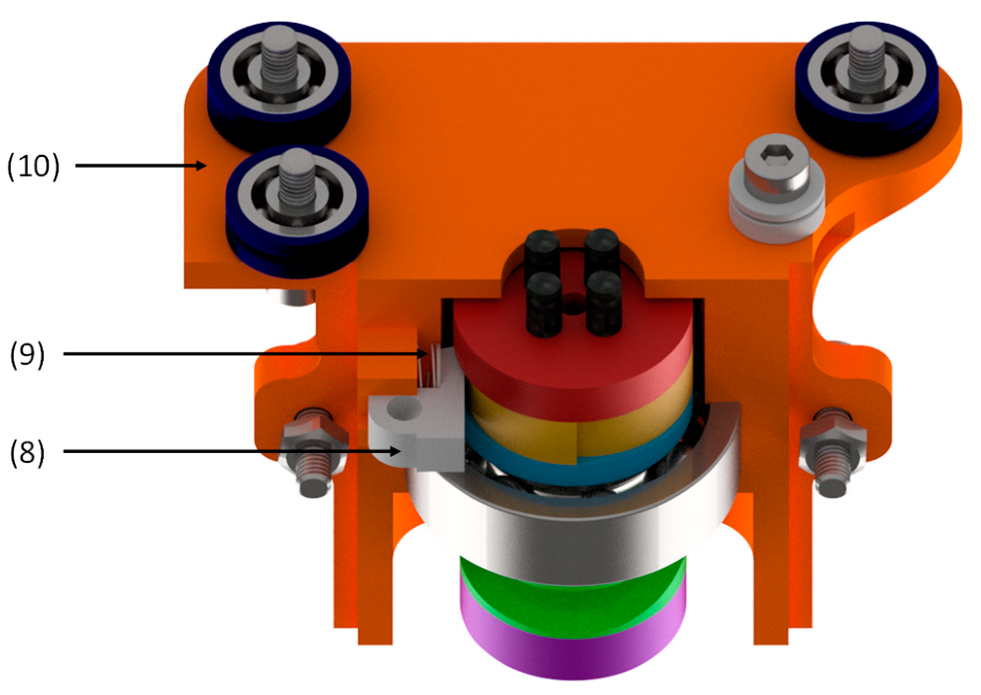
| 8 | pawl | grey (light) |
| 9 | pawl spring | grey |
| 10 | lower case | orange (dark) |
| 11 | upper case | orange (dark) |
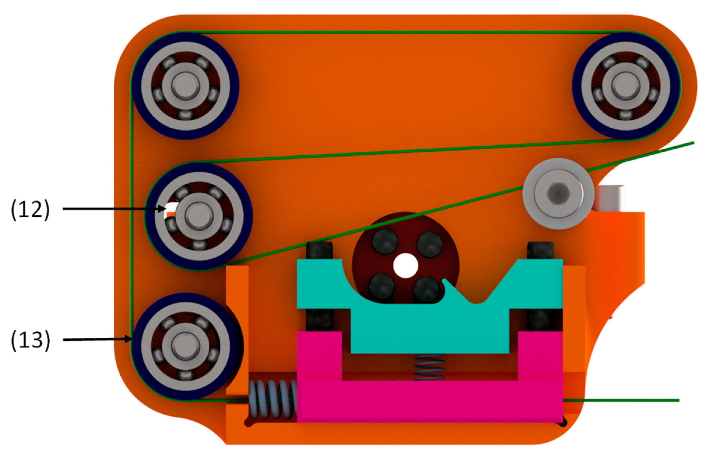
| 12 | bearing (small) (SKF 623-2Z) | silver |
| 13 | deflection | blue (dark) |
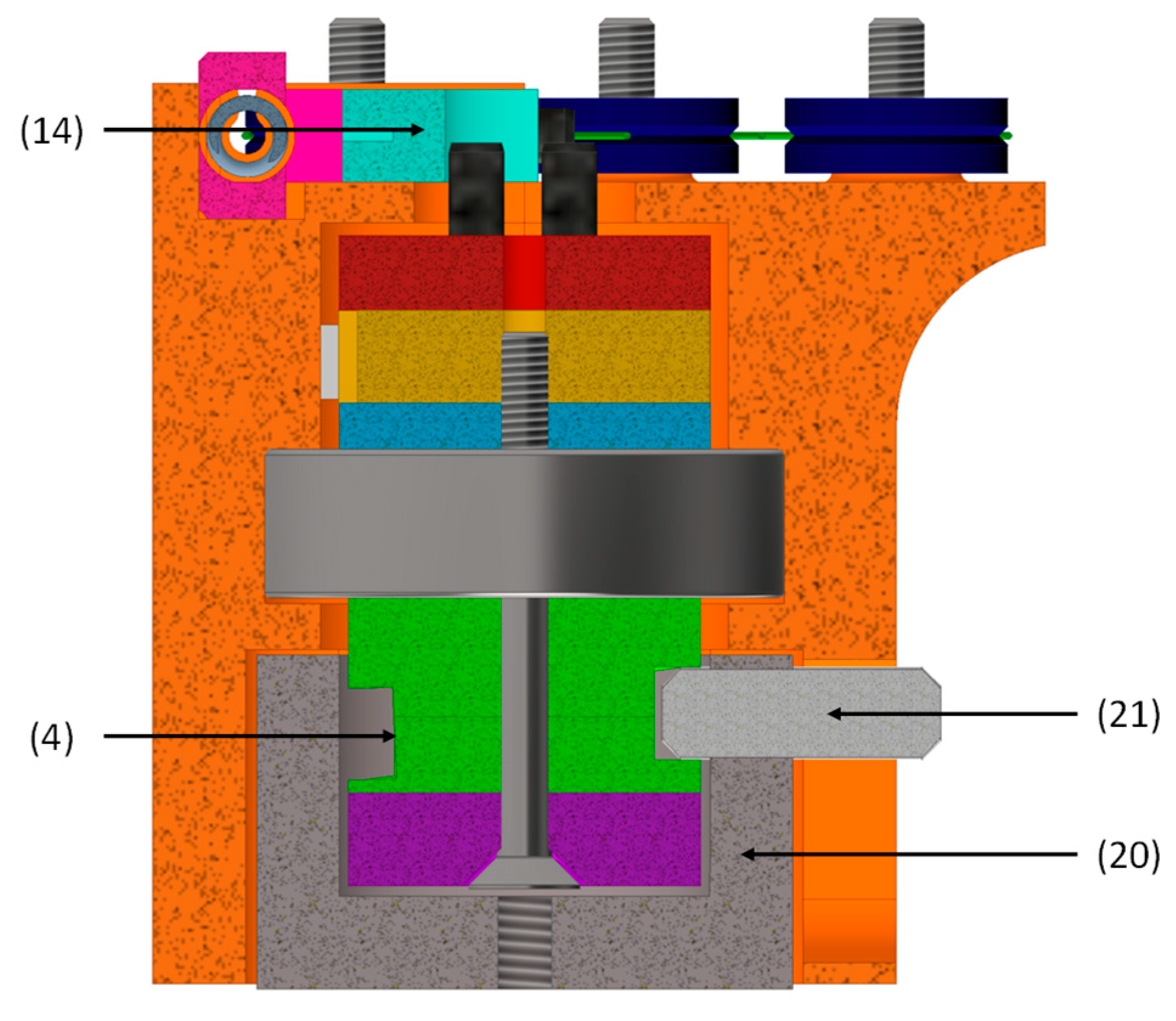
| 14 | shift fork | turquoise |
| 15 | carriage | pink |
| 16 | guide pin (ISO 8734–3 × 10) | black |
| 17 | compression spring | grey |
| 18 | counter spring | grey |
| 19 | wire | green (dark) |
| 20 | ring | grey (dark) |
| 21 | interface pin | grey |
| 22 | screw (short) (ISO 4762–M3 × 8) | silver |
| 23 | nut (ISO 4032–M3) | silver |
| 23 | screw (long) (ISO 4762–M3 × 12) | silver |
| 24 | screw (shaft) (DIN 7991–M3 × 30) | silver |
| Specification | Variable | Unit | Formula | Value |
|---|---|---|---|---|
| Initial Values | ||||
| stroke (actuator) | mm | 1.732 | ||
| Assumptions and Constants | ||||
| safety factor (for friction compensation) | 1.4 | |||
| elongation SMA wire (performance value) | 0.025 | |||
| Design Parameters | ||||
| number of switching positions | 4 | |||
| number of switching ramps | 4 | |||
| circumference of shaft | mm | 31.42 | ||
| wire diameter | m | 3.53 × 10⁻⁴ | ||
| lever length trigger pin | m | 3.536 × 10⁻³ | ||
| stroke SMA-wire | m | 5.4 | ||
| recommended wire force (data sheet) | N | 33 | ||
| maximum spring force return spring | N | 41 | ||
| maximum spring force pawl | N | 3.03 | ||
| maximum spring force carriage | N | 1.49 | ||
| maximum gradient groove | ° | read out of the CAD file | 12.44 | |
| Calculations | ||||
| required wire length | m | 0.216 | ||
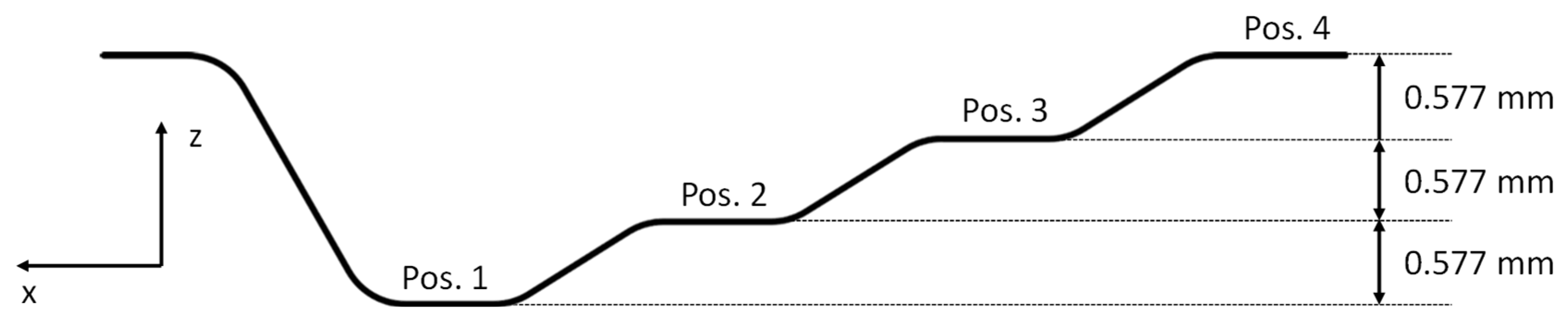
| stroke of the actuator per switching operation | mm | 0.577 | ||
| switching ramp length | mm | 7.854 | ||
| Parameters | Value | Unit |
|---|---|---|
| diameter wire | 0.353 mm | mm |
| wire manufacturer | SAES Getters | - |
| alloy | SmartFlex SF90 | - |
| As | >80 | °C |
| voltage | 6.8 | V |
| activation time | 2 | s |
| cooling duration | 16 | s |
| cycles | 10 | - |
Publisher’s Note: MDPI stays neutral with regard to jurisdictional claims in published maps and institutional affiliations. |
© 2021 by the authors. Licensee MDPI, Basel, Switzerland. This article is an open access article distributed under the terms and conditions of the Creative Commons Attribution (CC BY) license (http://creativecommons.org/licenses/by/4.0/).
Share and Cite
Schmelter, T.; Theren, B.; Fuchs, S.; Kuhlenkötter, B. Development of an Actuator for Translatory Movement by Means of a Detented Switching Shaft Based on a Shape Memory Alloy Wire for Repeatable Mechanical Positioning. Crystals 2021, 11, 163. https://doi.org/10.3390/cryst11020163
Schmelter T, Theren B, Fuchs S, Kuhlenkötter B. Development of an Actuator for Translatory Movement by Means of a Detented Switching Shaft Based on a Shape Memory Alloy Wire for Repeatable Mechanical Positioning. Crystals. 2021; 11(2):163. https://doi.org/10.3390/cryst11020163
Chicago/Turabian StyleSchmelter, Tobias, Benedict Theren, Sebastian Fuchs, and Bernd Kuhlenkötter. 2021. "Development of an Actuator for Translatory Movement by Means of a Detented Switching Shaft Based on a Shape Memory Alloy Wire for Repeatable Mechanical Positioning" Crystals 11, no. 2: 163. https://doi.org/10.3390/cryst11020163