Article

Enhanced Microwave Dielectric Properties and Sintering Behaviors of Mg2SiO4-Li2TiO3-LiF Ceramics by Adding CaTiO3 for LTCC and GPS Antenna Applications

1
Lab of Dielectric Materials, School of Materials Science and Engineering, Zhejiang University, Hangzhou 310027, China
2
Jiaxing Key Laboratory of Flexible Electronics-Based Intelligent Sensing and Advanced Manufacturing Technology, Institute of Flexible Electronics Technology of THU, Jiaxing 314006, China
3
State Key Laboratory of Chemical Engineering, College of Chemical and Biological Engineering, Zhejiang University, Hangzhou 310027, China
*
Author to whom correspondence should be addressed.
Crystals 2022, 12(4), 512; https://doi.org/10.3390/cryst12040512
Submission received: 28 February 2022 / Revised: 1 April 2022 / Accepted: 6 April 2022 / Published: 7 April 2022
(This article belongs to the Special Issue Advanced Electronic Ceramics)

Abstract

:
Mg2SiO4 holds promise for its application in the microwave communication field due to its low dielectric constant and high Q×f value. However, its high negative τf and high sintering temperature limit its application in low-temperature co-fired ceramic (LTCC) devices. In this work, Li2TiO3 and CaTiO3 were introduced to improve the τf, and LiF was chosen to decrease the sintering temperature. According to XRD patterns and SEM micrographs, the ceramic systems displayed a complex-phase structure, and the microstructure was densified when CaTiO3 was added. All of the relative densities, dielectric constants, and Q×f values first increased and then decreased as the sintering temperature increased. The MLLC11.5 ceramics sintered at 800 °C could be obtained with the highest Q×f value of 54,581 GHz (at 8.06 GHz), εr of 14.13, and τf of + 5.81 ppm/°C. Furthermore, it was proven that the MLLC11.5 powders could be co-fired without any reaction with Ag powders at 800 °C, indicating its potential for LTCC application. The MLLC11.5 composition was used to prepare a GPS antenna and showed good prospects for its application in electronic communications.

1. Introduction

As a multilayer ceramic manufacturing technology, low-temperature co-fired ceramic (LTCC) technology enables fabricating multilayer circuit boards and embedding passive devices with negligible packaging costs. Additionally, the devices tend to be smaller, thinner, and lighter due to the three-dimensional package. The conditions of large current and high-temperature resistance can also be satisfied by LTCC technology, contributing to the optimization of the thermal design of electronics. Catering to LTCC application, the ceramics must have a low dielectric constant (εr < 15), a high quality factor (Q×f), and a near-zero temperature coefficient of resonant frequency (τf ~ ±10 ppm/°C), which can guarantee the LTCC devices have high-frequency and high-speed transmission performance. Therefore, developing ceramics with excellent microwave dielectric properties (MWDPs) and lower sintering temperatures than the melting point of Ag (~961 °C) has become one of the most important topics in the research of microwave dielectric materials.
A lot of low-dielectric materials have been reported, such as Silicates [1,2,3,4], tungstates [5,6,7], germanates [8,9,10,11,12], borates [13], molybdates [14], phosphates [15,16], and some oxides [17,18]. Among them, Mg2SiO4, which exhibits excellent MWDPs (εr = 6–7, Q×f = 240,000 GHz) [19], is suitable for fabricating LTCC devices. Nevertheless, the negative and large τf (~−60 ppm/°C) and the high sintering temperature (≥1350 °C) of Mg2SiO4 weaken the frequency stability of the devices and limit their application in the LTCC field. Many studies have reported that the τf of Mg2SiO4 ceramics can be improved by doping ions [20,21] or adding a compound with a large positive τf value, such as TiO2 [22,23], CaTiO3 [24], and Ca0.9Sr0.1TiO3 [25], but these compounds generally have a small Q×f value and often decrease the Q×f value of Mg2SiO4 ceramics. The poor sintering behavior and decreased Q×f value of Mg2SiO4 ceramics can be attributed to the metastable enstatite or protoenstatite (MgSiO3) secondary phases induced by the conventional solid-state method [26]. To solve these two problems, it has been proven that the phase of MgSiO3 can be restrained by increasing the content of MgO, leading to an improved Q×f value [26,27]. MgSiO3 can also be eliminated by a two-step sintering process and mechanical activation [28]. The high sintering temperature of Mg2SiO4 ceramics can be lowered by adding an additive with a low melting point, such as LiF [29], Bi2O3-Li2CO3-H3BO3 [24], low-melting-point glass [30,31], or Ba3(VO4)2 [32]. In other words, the MWDPs and sintering behaviors of Mg2SiO4 ceramics can be enhanced by adding additives, which often exist in the form of secondary phases.
In this work, Mg2SiO4-Li2TiO3-LiF ceramics were chosen as the research system, in which Li2TiO3 and LiF were introduced to improve the MWDPs and sintering behaviors, respectively, because Li2TiO3 has a high Q×f value (~66,000 GHz) and a positive τf value (~+22.1 ppm/°C) [33], and LiF has a high Q×f value (~73,880 GHz) and a low melting point (~845 °C) [34]. Moreover, Li2TiO3 could form a limited solid solution with LiF, contributing to the densification of the ceramic system. Finally, the composition of (61 wt% Mg2SiO4-39 wt% Li2TiO3)-8 wt% LiF was selected, and the MWDPs and sintering behaviors were further improved by adding CaTiO3, and the optimized composition was demonstrated to enable LTCC and GPS antenna application.

2. Materials and Methods

Mg2SiO4 (MSO) powders were first synthesized by the conventional solid-state method with the raw materials of MgO (99.9%, Shanghai Macklin Biochemical Co., Ltd., Shanghai, China) and SiO2 (99.99%, Shanghai Macklin Biochemical Co., Ltd., Shanghai, China) according to the Mg2SiO4 stoichiometric ratio calcined at different temperatures (1250 °C, 1300 °C, 1350 °C, and 1400 °C) for 3 h. (61 wt% Mg2SiO4-39 wt% Li2TiO3)-8 wt% LiF-x wt% CaTiO3 ceramics (x = 0, 7.5, 8.5, 9.5, 10.5, and 11.5; MLL, MLLC7.5, MLLC8.5, MLLC9.5, MLLC10.5, and MLLC11.5 for short, respectively) were prepared by the conventional solid-state reaction process using the starting materials including the composite Mg2SiO4, Li2TiO3 (99%, Shanghai Aladdin Biochemical Technology Co., Ltd., Shanghai, China), LiF (99.99%, Shanghai Aladdin Biochemical Technology Co., Ltd., Shanghai, China) and CaTiO3 (99.5%, Shanghai Aladdin Biochemical Technology Co., Ltd., Shanghai, China). The mixed powders were ball-milled in absolute ethyl alcohol for 24 h. After the slurry was dried, the homogeneous powders were obtained and pressed into pellets, approximately 12 mm in diameter and 6 mm in thickness using 200 MPa pressure and 5% PVA binder. When burning out the binder at 600 °C for 2 h, all the samples were sintered at 775 °C, 800 °C, 825 °C, and 850 °C for 4 h in air using a muffle. To verify LTCC application, 40 wt% Ag powders were mixed with the MLLC11.5 powders without sintering, using the magnetic stirring method in absolute ethyl alcohol for 8 h. After mixing well and drying, the homogeneous powders were sintered at 800 °C for 4 h. The MLLC11.5 green body was coated with silver slurry and then sintered at 800 °C for 4 h. The GPS antenna was designed using HFSS software and prepared using the screen-printing method.
The crystal structures and microstructures of all the samples were examined by X-ray diffraction (XRD, SmartLab 3 KW, Rigaku, Tokyo, Japan) and scanning electron microscopy (SEM, Regulus8100, Hitachi, Tokyo, Japan), respectively. The elemental analysis used energy-dispersive X-ray spectroscopy (EDS) included in the SEM. The volume densities were obtained according to the Archimedes method, and the theoretical densities (Dt) were calculated according to Equation (1)
D t = 1 / i = 1 n ρ w i D t i , ( n 2 )
where ρwi and Dti are the weight percentage and theoretical density of the i-th phase, respectively, estimated from the Rietveld refinement results. The relative density is the proportion of the volume density to the theoretical density. εr and Q×f are evaluated at about 25 °C by a vector network analyzer (E8363B, Agilent, California, USA). The frequency range is about 8.06 GHz–8.55 GHz. τf is calculated according to Equation (2) by measuring the resonant frequencies at 20 °C (f20) and 80 °C (f80). All the error bars were obtained from three groups of data.
τ f = f 80 f 20 f 20 ( 80 20 ) × 10 6 ( ppm / ° C )

3. Results and Discussion

Figure 1 shows the XRD patterns of the MSO powders calcined at different temperatures. As can be seen from Figure 1a, the MSO phase (ICDD 01-074-0714) was discovered in all the samples, combined with the secondary phases identified as MgSiO3 and MgO, which decreased with the increase in calcining temperature, as shown in Figure 1b,c. The SiO2 phase was detected when the powders were calcined at 1250 °C, while there was no SiO2 phase when the powders were calcined at temperatures more than 1250 °C. Thus, it was too troublesome to obtain the composition of the pure MSO phase by the conventional solid-state method, as the MgSiO3 phase and residual MgO phase always emerged, induced by a small amount of amorphous SiO2 at high temperatures [26]. When the calcining temperature increased, the residual MgO reacted with MgSiO3, leading to an increase in the MSO phase [26]. Considering many clumps in the MSO powders calcined at 1400 °C, the optimum calcining temperature was selected as 1350 °C for the MSO powders in this work.
Figure 2a shows the XRD patterns of the MLLC ceramics sintered at 800 °C. A principal crystalline phase identified as Mg2SiO4 (ICDD 01-074-0714) was detected for all the samples. The secondary phases could be identified as LiTiO2, SiO2, Li2TiO3, Li2MgSiO4, and CaTiO3. No LiF phase was discovered from the XRD patterns of the MLLC ceramics, which could be attributed to the solid solution formation between Li2TiO3 and LiF [35]. Due to this solid solution, Li+ and F ions entered into Li2TiO3 lattice and formed the LiTiO2 phase, which could also be produced in ceramic systems with an excess MgO content [36,37]. The phases of MgSiO3, MgO, and amorphous SiO2 react with Li2TiO3, leading to the formation of Li2MgSiO4 and LiTiO2, according to the following reactions:
2 L i 2 Ti O 3 + MgO + Si O 2 L i 2 MgSi O 4 + 2 LiTi O 2 + 1 2 O 2
2 L i 2 Ti O 3 + MgSi O 3 L i 2 MgSi O 4 + 2 LiTi O 2 + 1 2 O 2
As shown in Figure 2a, the CaTiO3 phase existed in the ceramic systems in the form of the secondary phase without reaction with other phases. Rietveld refinements using Fullprof software were introduced to confirm the weight percentage and the theoretical density of each phase in the MLL ceramic without CaTiO3, as shown in Figure 2b. The ion occupancy was revised based on the crystal structures of Li2MgSiO4, SiO2, Li2TiO3, LiTiO2, and Mg2SiO4. The XRD pattern of the MLL ceramic displayed good refinement. The refinement result is shown in Table 1. The theoretical density of the MLL ceramic was calculated according to Equation (1), with a value of about 3.381 g/cm3. As CaTiO3 could not react with the MLL, the theoretical densities of the MLLC ceramics could also be calculated according to Equation (1).
Figure 3 shows the SEM micrographs of the cross-sections of the MLLC ceramics sintered at 800 °C. No grain changes were discovered for any of the samples when increasing the CaTiO3 content. Some pores were detected for the MLL ceramic, and a dense microstructure was detected for all the samples with CaTiO3 additives, which indicated that CaTiO3 additives could promote the densification of the MLLC ceramics. Figure 4 shows the SEM micrographs of the cross-sections of the MLLC9.5 ceramics sintered at different temperatures. The micrograph differences between Figure 4a–d could be due to the breaking of the ceramics, leading to different flatnesses. The grain size of the MLLC9.5 ceramic increased with the increase in the sintering temperature, and some pores were observed in all the samples except for those sintered at 800 °C, indicating that 800 °C was the optimal sintering temperature of the MLLC ceramics.
Figure 5 shows the relative densities, volume densities, dielectric constants, Q×fs, and τfs of the MLLC ceramics. All the relative densities, volume densities, dielectric constants, and Q×f values first increased and then decreased with the increase in the sintering temperature and achieved a maximum value in the samples sintered at 800 °C. When the sintering temperatures were higher than 800 °C, the air in the ceramics could not escape in time, and isolated pores remained trapped, resulting in higher porosity [38]. The dielectric constants and Q×f values changed with the relative densities, which indicated that porosity played an important role in the MWDPs. The dielectric constants also varied in the additive amount of CaTiO3 content due to the high dielectric constant of CaTiO3 ceramics (~162) [39]. After adding the CaTiO3 additives, an obvious increase in the relative density, dielectric constant, and Q×f was observed for all the MLLC ceramics, revealing that the MWDPs were improved with the decrease in porosity. The τfs of the MLLC ceramics sintered at 800 °C increased linearly with the increase in the CaTiO3 content. The variation of τfs could mainly be attributed to the CaTiO3 content and described according to the Lichtenecker empirical rule
τ f = V 1 τ f 1 + V 2 τ f 2
where V1 and V2 are the volume fractions and τf1 and τf2 are the τf value of each phase. The increase in the τf value could be due to the increased concentration of the CaTiO3 phase, which was reported to have a high positive τf value of +859 ppm/°C [39]. A near-zero τf value of +5.81 ppm/°C was obtained for the MLLC11.5 ceramics sintered at 800 °C with an optimal Q×f value of 54,581 GHz (at 8.06 GHz) and a low εr value of 14.13.
As seen from the XRD pattern of MLLC11.5-40wt%Ag powders sintered at 800 °C in Figure 6a, Ag powders could not react with MLLC11.5 powders and mainly existed in the form of the secondary phase. Figure 6b shows a SEM micrograph of the cross-section of the MLLC11.5 ceramic, whose surface was coated with silver slurry. The ceramic was co-fired at 800 °C for 4 h and displayed a clear interface between the solidified silver slurry and the ceramic, marked as a and b, respectively. Figure 6c,d show the elemental analysis results of areas a and b by EDS, which displayed that areas a and b belonged to Ag and the MLLC11.5 ceramic, respectively. This result indicates that MLLC11.5 ceramics could be suitable for LTCC application.
The MLLC11.5 composition was also employed to prepare a GPS antenna composed of a ground plane, radiation layer, and dielectric substrate. The designed sample is shown in Figure 7a. The dielectric substrate was the MLLC11.5 ceramic, about 1.5 mm thick and 21 mm in diameter. The radiation layer was a camber line with a 1 mm width, whose length could be modified to satisfy the GPS frequency (~1.575 GHz). Another part of the front face was the ground plane, which also included a part of the side face and half of the back face of the dielectric substrate. Considering the size limit of the dielectric substrate, the radiation layer could connect with the ground plane through a metal wire with 50 Ω impedance, which could increase the inductance of the antenna to reduce the resonant frequency. The GPS antenna was designed with HFSS software and prepared with the screen-printing process according to the designed size. The front and back face of the GPS antenna is shown in Figure 7b,c, respectively. The metal pattern of the side face was handmade. The soldering was guaranteed by thickening and widening the silver slurry of the solder joint position. Figure 7d shows the return loss (S11) of the GPS antenna. Both the simulated and experimental data of the S11 were less than −10 dB at the resonant frequency. By modifying the length of the radiation layer, the resonant frequency was improved and nearly identical to the simulated data. The GPS signal test was carried out for the antenna by using a hardware system and displayed in the software, as shown in Figure 7e. A total of 11 or 12 Pcs GPS satellites were detected at the same time and displayed more than a 28 dBHz carrier-to-noise ratio (C/N0) on average, indicating antenna application [40].

4. Conclusions

MLLC ceramics with different amounts of CaTiO3 additives were prepared using the conventional solid-state method. The effects of CaTiO3 contents on the structures, sintering behaviors, and MWDPs were studied. A mixed-phase structure composed of Mg2SiO4, LiTiO2, Li2TiO3, Li2MgSiO4, SiO2, and CaTiO3 was detected using the XRD pattern. The relative density significantly increased after adding CaTiO3, leading to a significantly increased Q×f. The dielectric constant and Q×f first increased and then decreased with the increase in the sintering temperature, and achieved a maximum value when the MLLC11.5 ceramics were sintered at 800 °C with an εr of 14.13 and Q×f of 54,581 GHz (at 8.06 GHz). The τf increased linearly with the increase in the CaTiO3 content and reached three near-zero values of −5, +2.59, and +5.81 ppm/°C for MLLC9.5, MLLC10.5, and MLLC11.5 compositions, respectively. The MLLC11.5 composition could be co-fired without any reaction with Ag powders at 800 °C, indicating LTCC application. In the investigation of the GPS antenna, the MLLC11.5 composition exhibited good potential for antenna application.

Author Contributions

Conceptualization, Z.W. and Y.C.; methodology, Z.W. and F.P.; validation, Z.W. and Y.C.; investigation, Z.W., F.P. and L.L.; resources, Y.C.; data curation, Z.W. and Y.C.; writing—original draft preparation, Z.W.; writing—review and editing, Z.W., Q.D., R.T. and Y.C.; visualization, J.A. and H.Z.; supervision, Y.C.; project administration, Y.C.; and funding acquisition, Y.C. All authors have read and agreed to the published version of the manuscript.

Funding

This research was funded by the Zhejiang Province Key Research and Development Project (Grant Nos. 2019C05002, 2020C05004, 2021C01183), National Natural Science Foundation of China (Grant No. 11902292), Postdoctoral Program of Zhejiang Province (Grant No. ZJ2020018), Natural Science Foundation of Zhejiang Province (Grant Nos. LQ20E030008, LQ20E050014, LQ20A020005, LGG20E050011) and National Key Research and Development Program of China (Grant No. 2020YFC2007101).

Institutional Review Board Statement

Not applicable.

Informed Consent Statement

Not applicable.

Data Availability Statement

The data presented in this study are available upon request from the corresponding author.

Conflicts of Interest

The authors declare no conflict of interest.

References

  1. Song, X.; Du, K.; Li, J.; Muhammad, R.; Lu, W.; Wang, X.; Lei, W. Crystal structures and microwave dielectric properties of novel low-permittivity Ba1−xSrxZnSi3O8 ceramics. Mater. Res. Bull. 2019, 112, 178–181. [Google Scholar] [CrossRef]
  2. Lai, Y.; Su, H.; Wang, G.; Tang, X.; Liang, X.; Huang, X.; Li, Y.; Zhang, H.; Ye, C.; Wang, X.R. Improved microwave dielectric properties of CaMgSi2O6 ceramics through CuO doping. J. Alloys Compd. 2019, 772, 40–48. [Google Scholar] [CrossRef]
  3. Lai, Y.; Tang, X.; Zhang, H.; Liang, X.; Huang, X.; Li, Y.; Su, H. Correlation between structure and microwave dielectric properties of low-temperature-fired Mg2SiO4 ceramics. Mater. Res. Bull. 2018, 99, 496–502. [Google Scholar] [CrossRef]
  4. Wang, H.; Chen, J.; Yang, W.; Feng, S.; Ma, H.; Jia, G.; Xu, S. Effects of Al2O3 addition on the sintering behavior and microwave dielectric properties of CaSiO3 ceramics. J. Eur. Ceram. Soc. 2012, 32, 541–545. [Google Scholar] [CrossRef]
  5. Li, J.; Fang, L.; Luo, H.; Khaliq, J.; Tang, Y.; Li, C. Li4WO5: A temperature stable low-firing microwave dielectric ceramic with rock salt structure. J. Eur. Ceram. Soc. 2016, 36, 243–246. [Google Scholar] [CrossRef]
  6. Zhou, D.; Randall, C.A.; Pang, L.; Wang, H.; Guo, J.; Zhang, G.; Wu, X.; Shui, L.; Yao, X. Microwave Dielectric Properties of Li2WO4 Ceramic with Ultra-Low Sintering Temperature. J. Am. Ceram. Soc. 2011, 94, 348–350. [Google Scholar] [CrossRef]
  7. Dong, H.L.; Hu, C.X.; Wang, W.J.; Bao, H.P.; Liu, W.J.; Yang, B. Novel Low-Permittivity, Low-Sintering-Temperature Na2WO4 Microwave Dielectric Ceramics for LTCC Applications. J. Ceram. Sci. Technol. 2018, 9, 471–475. [Google Scholar]
  8. Cheng, K.; Li, C.; Xiang, H.; Sun, Y.; Fang, L. LiYGeO4: Novel low-permittivity microwave dielectric ceramics with intrinsic low sintering temperature. Mater. Lett. 2018, 228, 96–99. [Google Scholar] [CrossRef]
  9. Yin, C.; Xiang, H.; Li, C.; Porwal, H.; Fang, L. Low-temperature sintering and thermal stability of Li2GeO3-based microwave dielectric ceramics with low permittivity. J. Am. Ceram. Soc. 2018, 101, 4608–4614. [Google Scholar] [CrossRef] [Green Version]
  10. Ma, X.; Kweon, S.; Im, M.; Nahm, S. Low-temperature sintering and microwave dielectric properties of B2O3-added ZnO-deficient Zn2GeO4 ceramics for advanced substrate application. J. Eur. Ceram. Soc. 2018, 38, 4682–4688. [Google Scholar] [CrossRef]
  11. Tang, Y.; Xu, M.; Duan, L.; Chen, J.; Li, C.; Xiang, H.; Fang, L. Structure, microwave dielectric properties, and infrared reflectivity spectrum of olivine type Ca2GeO4 ceramic. J. Eur. Ceram. Soc. 2019, 39, 2354–2359. [Google Scholar] [CrossRef]
  12. Luo, H.; Fang, L.; Xiang, H.; Tang, Y.; Li, C. Two novel low-firing germanates Li2MGe3O8 (M = Ni, Co) microwave dielectric ceramics with spinel structure. Ceram. Int. 2017, 43, 1622–1627. [Google Scholar] [CrossRef]
  13. Chang, S.; Pai, H.; Tseng, C.; Tsai, C. Microwave dielectric properties of ultra-low temperature fired Li3BO3 ceramics. J. Alloys Compd. 2017, 698, 814–818. [Google Scholar] [CrossRef]
  14. Ren, J.; Bi, K.; Fu, X.; Peng, Z. Novel Al2Mo3O12-based temperature-stable microwave dielectric ceramics for LTCC applications. J. Mater. Chem. C 2018, 6, 11465–11470. [Google Scholar] [CrossRef]
  15. Zhang, P.; Wu, S.; Xiao, M. The microwave dielectric properties and crystal structure of low temperature sintering LiNiPO4 ceramics. J. Eur. Ceram. Soc. 2018, 38, 4433–4439. [Google Scholar] [CrossRef]
  16. Peng, R.; Li, Y.; Yu, G.; Lu, Y.; Li, S. Effect of Co2+ Substitution on the Microwave Dielectric Properties of LiZnPO4 Ceramics. J. Electron. Mater. 2018, 47, 7281–7287. [Google Scholar] [CrossRef]
  17. Penn, S.J.; Alford, N.M.; Templeton, A.; Wang, X.R.; Xu, M.S.; Reece, M.; Schrapel, K. Effect of porosity and grain size on the microwave dielectric properties of sintered alumina. J. Am. Ceram. Soc. 1997, 80, 1885–1888. [Google Scholar] [CrossRef]
  18. Li, L.; Liu, C.H.; Zhu, J.Y.; Chen, X.M. B2O3-modified fused silica microwave dielectric materials with ultra-low dielectric constant. J. Eur. Ceram. Soc. 2015, 35, 1799–1805. [Google Scholar] [CrossRef]
  19. Tsunooka, T.; Androu, M.; Higashida, Y.; Sugiura, H.; Ohsato, H. Effects of TiO2 on sinterability and dielectric properties of high-Q forsterite ceramics. J. Eur. Ceram. Soc. 2003, 23, 2573–2578. [Google Scholar] [CrossRef]
  20. Hameed, I.; Li, L.; Liu, X.Q.; Chen, X.M. Ultra low loss (Mg1−xCax)2SiO4 dielectric ceramics (x = 0 to 0.15) for millimeter wave applications. J. Am. Ceram. Soc. 2022, 105, 2010–2019. [Google Scholar] [CrossRef]
  21. Song, K.X.; Chen, X.M. Phase evolution and microwave dielectric characteristics of Ti-substituted Mg2SiO4 forsterite ceramics. Mater. Lett. 2008, 62, 520–522. [Google Scholar] [CrossRef]
  22. Cheng, Z.; Hu, X.; Li, Y.; Ling, Z. Fabrication and Microwave Dielectric Properties of Mg2SiO4-LiMgPO4-TiO2 Composite Ceramics. J. Am. Ceram. Soc. 2016, 99, 2688–2692. [Google Scholar] [CrossRef]
  23. Kagomiya, I.; Sugihara, J.; Kakimoto, K.; Ohsato, H. Mg2SiO4-TiO2 composite ceramics prepared using a liquid phase deposition process. J. Electroceram. 2009, 22, 327–333. [Google Scholar] [CrossRef]
  24. Dou, G.; Zhou, D.; Guo, M.; Gong, S.; Hu, Y. Low-temperature sintered Mg2SiO4-CaTiO3 ceramics with near-zero temperature coefficient of resonant frequency. J. Mater. Sci.-Mater. Electron. 2013, 24, 1431–1438. [Google Scholar] [CrossRef]
  25. Feng, Q.; Liu, P.; Fu, Z.; Zhao, L.; Ren, Y. Microwave dielectric properties of low-fired (1−x)Mg2SiO4−xCa0.9Sr0.1TiO3 ceramics by using nanopowders from high energy ball milling. J. Mater. Sci. Mater. Electron. 2017, 28, 15398–15404. [Google Scholar] [CrossRef]
  26. Song, K.X.; Chen, X.M.; Fan, X.C. Effects of Mg/Si Ratio on Microwave Dielectric Characteristics of Forsterite Ceramics. J. Am. Ceram. Soc. 2007, 90, 1808–1811. [Google Scholar] [CrossRef]
  27. He, G.; Li, Z.; Dong, Y.; Wang, G. Effects of excessive magnesium oxide and sintering regime on microstructure and dielectric properties of forsterite ceramics for millimeterwave dielectrics. J. Mater. Sci.-Mater. Electron. 2022, 33, 3129–3138. [Google Scholar] [CrossRef]
  28. Roshni, S.B.; Arun, S.; Sebastian, M.T.; Mohanan, P.; Surendran, K.P. Low κ Mg2SiO4 ceramic tapes and their role as screen printed microstrip patch antenna substrates. Mater. Sci. Eng. B 2021, 264, 114947. [Google Scholar] [CrossRef]
  29. Ma, J.; Yang, T.; Fu, Z.; Liu, P.; Feng, Q.; Zhao, L. Low-fired Mg2SiO4-based dielectric ceramics with temperature stable for LTCC applications. J. Alloys Compd. 2017, 695, 3198–3201. [Google Scholar] [CrossRef]
  30. Sasikala, T.S.; Pavithran, C.; Sebastian, M.T. Effect of lithium magnesium zinc borosilicate glass addition on densification temperature and dielectric properties of Mg2SiO4 ceramics. J. Mater. Sci.-Mater. Electron. 2010, 21, 141–144. [Google Scholar] [CrossRef]
  31. Yang, H.; Li, E.; Sun, C.; Duan, S.; Yuan, Y.; Tang, B. The Influence of Sintering Temperature on the Microwave Dielectric Properties of Mg2SiO4 Ceramics with CaO-B2O3-SiO2 Addition. J. Electron. Mater. 2017, 46, 1048–1054. [Google Scholar] [CrossRef]
  32. Meng, S.; Yue, Z.; Zhuang, H.; Zhao, F.; Li, L. Microwave Dielectric Properties of Ba3(VO4)2-Mg2SiO4 Composite Ceramics. J. Am. Ceram. Soc. 2010, 93, 359–361. [Google Scholar] [CrossRef]
  33. Bian, J.J.; Dong, Y.F. Sintering behavior, microstructure and microwave dielectric properties of Li2+xTiO3 (0 ≤ x ≤ 0.2). Mater. Sci. Eng. B 2011, 176, 147–151. [Google Scholar] [CrossRef]
  34. Song, X.; Du, K.; Li, J.; Lan, X.; Lu, W.; Wang, X.; Lei, W. Low-fired fluoride microwave dielectric ceramics with low dielectric loss. Ceram. Int. 2019, 45, 279–286. [Google Scholar] [CrossRef]
  35. Ding, Y.; Bian, J. Structural evolution, sintering behavior and microwave dielectric properties of (1−x)Li2TiO3 + xLiF ceramics. Mater. Res. Bull. 2013, 48, 2776–2781. [Google Scholar] [CrossRef]
  36. Bian, J.J.; Dong, Y.F. New high Q microwave dielectric ceramics with rock salt structures: (1−x)Li2TiO3 + xMgO system (0 ≤ x≤ 0.5). J. Eur. Ceram. Soc. 2010, 30, 325–330. [Google Scholar] [CrossRef]
  37. Lai, Y.; Hong, C.; Jin, L.; Tang, X.; Zhang, H.; Huang, X.; Li, J.; Su, H. Temperature stability and high-Qf of low temperature firing Mg2SiO4-Li2TiO3 microwave dielectric ceramics. Ceram. Int. 2017, 43, 16167–16173. [Google Scholar] [CrossRef]
  38. Kang, S.-J.L. Sintering: Densification, Grain Growth, and Microstructure, 1st ed.; Elsevier Butterworth-Heinemann: Oxford, UK; Burlington, MA, USA, 2005; pp. 67–68. [Google Scholar]
  39. Wise, P.L.; Reaney, I.M.; Lee, W.E.; Price, T.J.; Iddles, D.M.; Cannell, D.S. Structure-microwave property relations of Ca and Sr titanates. J. Eur. Ceram. Soc. 2001, 21, 2629–2632. [Google Scholar] [CrossRef]
  40. Tian, F.; Huang, Y.B.; Xu, B.; Ou, G. An Optimized Low-Power-Consumption Tracking Algorithm Based on Navigation Message Structure for Weak Signals. Appl. Mech. Mater. 2015, 733, 854–859. [Google Scholar] [CrossRef]
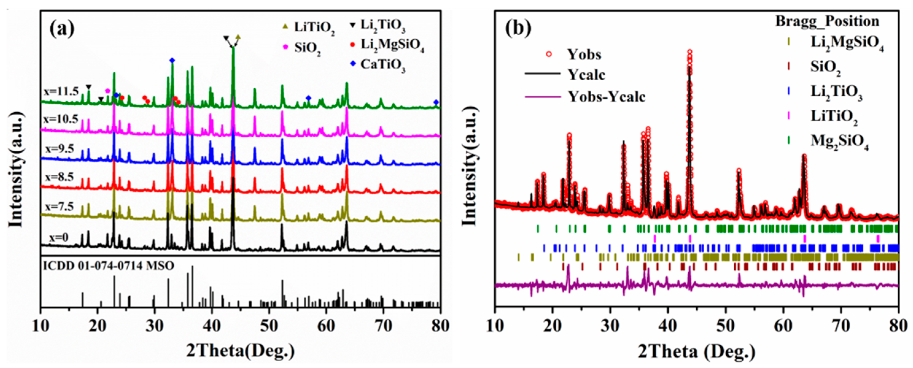
Figure 1. XRD patterns of the MSO powders calcined at different temperatures. (a) 10°–80°, (b) 26.5°–29.5°, and (c) 42.5°–43.25°.
Crystals 12 00512 g001
Figure 2. (a) XRD patterns of the MLLC ceramics sintered at 800 °C. (b) Rietveld refinement plots of the MLL ceramic.
Crystals 12 00512 g002
Figure 3. SEM micrographs of the cross-sections of the MLLC ceramics sintered at 800 °C. (a) MLL, (b) MLLC7.5, (c) MLLC8.5, (d) MLLC9.5, (e) MLLC10.5, and (f) MLLC11.5.
Crystals 12 00512 g003
Figure 4. SEM micrographs of the cross-sections of the MLLC9.5 ceramics sintered at different temperatures. (a) 775 °C, (b) 800 °C, (c) 825 °C, and (d) 850 °C.
Crystals 12 00512 g004
Figure 5. Relative densities, volume densities, and microwave dielectric properties of the MLLC ceramics. (a) Relative densities, (b) volume densities, (c) dielectric constants, (d) Q×fs, and (e) τfs of all the samples sintered at 800 °C.
Crystals 12 00512 g005
Figure 6. (a) XRD pattern of MLLC11.5-40 wt% Ag powders calcined at 800 °C, (b) SEM micrograph of the cross-section of MLLC11.5 ceramic coated with silver slurry and sintered at 800 °C, (c) EDS result of area a, and (d) EDS result of area b.
Crystals 12 00512 g006
Figure 7. GPS antenna application. (a) Designed sample, (b) front face of the GPS antenna, (c) back face of the GPS antenna, (d) return loss (S11), (e) experimental process of GPS signal, and (f) C/N0 and number of satellites.
Crystals 12 00512 g007
Table 1. Rietveld refinement result of the MLL ceramic.
PhaseDt (g/cm3)Vt (×106 pm3)ρt (wt%)Rwp (%)Rp (%)χ2D (g/cm3)
Mg2SiO43.311290.33759.0713.99.825.423.381
LiTiO24.06870.89024.18
Li2TiO33.404428.2528.60
Li2MgSiO42.575336.0596.27
SiO22.270175.8381.88
Rwp: reliability factor of weighted patterns; Rp: reliability factor of patterns; and χ2: goodness of fit.
Publisher’s Note: MDPI stays neutral with regard to jurisdictional claims in published maps and institutional affiliations.

