
Grain Boundary Wetting Transition in the Mg-Based ZEK 100 Alloy
by
 , ,
, ,
Boris Straumal
1,2,*, 
Natalya Khrapova
1,
Aleksandr Druzhinin
1,
Kristina Tsoy
1,
Gregory Davdian
1,2,
Valery Orlov
1,
Gregory Gerstein
3 and
Alexander Straumal
4 1
Osipyan Institute of Solid State Physics, The Russian Academy of Sciences, Ac. Osipyan Str. 2, 142432 Chernogolovka, Russia
2
Department of Physical Chemistry, National University of Science and Technology MISiS, Leninskiy Ave. 4, 119049 Moscow, Russia
3
Institute for Material Science, Leibniz Universität Hannover, An der Universität 2, 30823 Garbsen, Germany
4
Department of Materials for Agrotechnology, Cotton Breeding, Seed Production and Agrotechnologies Research Institute, University Str. 3, Salar, Tashkent 702147, Uzbekistan
*
Author to whom correspondence should be addressed.
Crystals 2023, 13(11), 1538; https://doi.org/10.3390/cryst13111538
Submission received: 30 September 2023
/
Revised: 20 October 2023
/
Accepted: 24 October 2023
/
Published: 26 October 2023
(This article belongs to the Special Issue High-Performance Heterogeneous Nanostructured Materials)
Abstract
:Modern magnesium-based alloys are broadly used in various industries as well as for biodegradable medical implants due to their exceptional combination of light weight, strength, and plasticity. The studied ZEK100 alloy had a nominal composition of 1 wt.% zinc, 0.1 wt.% zirconium, and 0.1 wt.% rare earth metals (REMs) such as Y, Ce, Nd, and La, with the remainder being Mg. It has been observed that between the solidus (Ts = 529.5 ± 0.5 °C) and liquidus temperature (Tl = 645 ± 5 °C), the Mg/Mg grain boundaries can contain either the droplets of a melt (incomplete or partial wetting) or the continuous liquid layers separating the abutting Mg grains (complete wetting). With the temperature increasing from Ts to Tl, the transformation proceeds from incomplete to complete grain boundary wetting. Below 565 °C, all grain boundaries are partially wetted by the melt. Above 565 °C, the completely wetted Mg/Mg grain boundaries appear. Their portion grows quickly with an increasing temperature until reaching 100% at 622 °C. Above 622 °C, all the solid Mg grains are completely surrounded by the melt. After rapid solidification, the REM-rich melt forms brittle intermetallic compounds. The compression strength as well as the compression yield strength parameter σ02 strongly depend on the morphology of the grain boundary layers. If the hard and brittle intermetallic phase has the shape of separated particles (partial wetting), the overall compression strength is about 341 MPa and σ02 = 101 MPa. If the polycrystal contains the continous intergarnular layers of the brittle intermetallic phase (complete wetting), the overall compression strength drops to 247 Mpa and σ02 to 40 Mpa. We for the first time observed, therefore, that the grain boundary wetting phenomena can strongly influence the mechanical properties of a polycrystal. Therefore, grain boundary wetting can be used for tailoring the behavior of materials.
1. Introduction
Exploration of Mg-based alloys has garnered increasing interest within contemporary materials science [1,2,3,4]. This keen attention is driven by the extensive application of these alloys in technologically advanced sectors. They are highly regarded for their lightweight nature, relatively commendable strength, and durability. Nevertheless, despite their strong demand, there remains ample room for enhancing their properties.
A significant challenge stems from magnesium’s hexagonal crystal structure, which offers less slip systems for dislocations in comparison to metals with cubic lattices like body-centered cubic (BCC) or face-centered cubic (FCC) ones. This inherent limitation results in decreased formability and heightened brittleness. To combat this challenge, extensive research and projects are underway to enhance the properties of Mg-based alloys. An important strategy for addressing this issue involves alloying with elements such as Zn, Zr, and rare earth metals (REMs). These alloying elements facilitate the formation of nuclei during crystallization. In such a way, they reduce the grain size and promote a more uniform spatial distribution of the basal plane orientation within grains of the Mg matrix [1,2,5,6,7,8].
Magnesium-based alloys, when infused with rare earth metals (REMs), demonstrate a remarkable performance compared to their conventional counterparts, particularly from the point of view of anisotropy and strain-rate sensitivity [9]. In contrast to the typical strong texturing found in traditional magnesium alloys like AZ31 [10], sheets made from the magnesium alloy ZEK100 exhibit a notably weaker texture [10,11,12,13,14]. The composition of the ZEK100 alloy typically comprises 1.3 wt.% zinc, 0.25 wt.% zirconium, 0.2 wt.% neodymium, and about 0.01 wt.% manganese [15].
A lot of efforts have been dedicated to exploring the mechanical properties of the ZEK100 alloy, encompassing a wide array of facets. These investigations have spanned assessments of warm and hot deformation behavior [16,17], damage and fracture analyses [18,19,20], examinations of the heterogeneous nature of plastic deformation [21], investigations into the propagation of plastic instability [22], scrutiny of yield asymmetry under tension and compression [23], and detailed exploration of processes such as extrusion [24,25], warm stamping [26], hot rolling [27], cyclic deformation, fatigue, and inelasticity [28,29,30,31,32,33]. To describe the performance of ZEK100, in-plane bending tests have been conducted, including three-point bending [34] and V-bend [35] tests. Furthermore, simulations have been employed to study twin formation [36], comprehensive forming limit diagrams have been constructed [37,38,39], and sophisticated constitutive plasticity models have been proposed [40,41,42,43,44,45,46] to both predict and elucidate the mechanical properties exhibited by this particular alloy.
The ZEK100 alloy finds extensive application as a biodegradable material in the field of prosthetics and implants [47,48,49,50,51,52,53,54,55,56,57,58,59,60,61,62], particularly in scenarios demanding precise corrosion resistance control [63,64,65,66,67,68,69,70,71] and enhanced mechanical properties [47,72]. Furthermore, this alloy serves as a structural component for myocardial stabilization [56,57,73] and functions as a wire reinforcement within phosphate-based composites designed for the substitution of bones [61,74]. In the manufacturing of ZEK100 alloy parts, state-of-the-art processing techniques are employed, including friction stir spot welding [75,76,77], ultrasonic spot welding [78,79,80], electric pulse processing [81], and laser welding/brazing [82,83]. Such approaches allow for the production of excellent components with specified attributes.
The modification of Mg-based alloys has brought forth novel and previously unexplored dimensions in their properties. The incorporation of alloying elements poses specific challenges, primarily stemming from the formation of precipitates, often concentrated at lattice defects, particularly the grain boundaries. Notably, rare earth metals have the capacity to create robust intermetallic compounds when Mg-alloyed. Such precipitates increase, obviously, the material’s strength. At the same time, they also introduce brittleness. This brittleness can be especially pronounced if the brittle intermetallic layers completely substitute the Mg/Mg grain boundaries. Consequently, during deformation, such fragile GB layers make the propagation of cracks easy, even if the Mg matrix is highly ductile. To effectively predict and address these scenarios, a thorough investigation of phase transitions is imperative, as they can profoundly influence the morphology of GB precipitates in multi-phase and polycrystalline Mg-based alloys. Therefore, the studies of mechanisms governing the appearance or degradation of GB layers is important to develop new alloys and to improve the existing ones.
The notion of surface phase transitions was originally introduced by Cahn and Ebner within a theoretical framework [84,85]. Their pioneering idea emphasized that phase transitions take place not only in the bulk but also in surfaces and interfaces. Such phase transformations include faceting [86,87,88,89] and surface wetting [90,91]. Over the years, extensive research has explored these phenomena for individual GBs [92,93] and their assemblies [92,94,95,96]. These surface phase transitions arise from disparities in the surface tension energies between the interphase boundaries (IBs) and grain boundaries (GBs) and can exhibit variability contingent upon pressure or temperature [97,98]. The equilibrium in this case depends on the contact angle θ described by Young’s formula at the contact line between two interphase boundaries (IBs) with energy σIB, and GBs with energy σGB:
σGB = 2 σIB cos θ.
When the difference between 2σIB, and σGB diminishes, the θ values also decrease. When 2σIB = σGB, θ becomes zero (θ = 0). From this point on, the GB is replaced with a layer of liquid (or second solid) phase, bounded by two interphase boundaries. Such a phenomenon is called the grain boundary wetting transition and the respective temperature, where 2σIB becomes equal to σGB, is denoted as Tw. Each grain boundary can possess a distinct structure, leading to varying σGB values. Consequently, this results in a range of wetting temperatures (Tw) for different grain boundaries. As a consequence, the polycrystal exhibits a spectrum of various Tw. The earlier research has predominantly centered on the EZ33A alloy, where we have observed the occurrence of wetting phase transitions within the grain boundaries, involving a secondary liquid and solid phase, across various temperature ranges [3,4,99]. EZ33A represents a magnesium casting alloy that finds widespread use in industrial applications, particularly for high-volume components like differential housings.
The findings of research studies [3,4,99] have unveiled an intriguing phenomenon in EZ33A alloys: slightly above the solidus line, at approximately 530 °C, already 10% of the grain boundaries are fully wetted by the melt. With the increasing temperature, the proportion of wetted grain boundaries steadily grows, reaching about 85% at 580 °C. At this particular temperature, it appears that the portion of completely wetted GBs reaches a saturation point. This saturation may be attributed to potential experimental inaccuracies stemming from the rapid cooling process at a high temperature or the presence of boundaries with minimal misorientation angles and/or coincident site lattice boundaries within the material. These GBs exhibit a lower energy σGB and may resist complete wetting in the alloy until it approaches its melting point. The goal of this work is to study the GB wetting transformations in another important Mg-based alloy, namely ZEK100 [9,10,11,12,13,14,15,16,17,18,19,20,21,22,23,24,25,26,27,28,29,30,31,32,33,34,35,36,37,38,39,40,41,42,43,44,45,46,47,48,49,50,51,52,53,54,55,56,57,58,59,60,61,62,63,64,65,66,67,68,69,70,71,72,73,74,75,76,77,78,79,80,81,82,83,84,85,86]. The ZEK100 alloy contains almost the same alloying elements as EZ33A but in lower amounts [3]. The main goal of this work is to find out whether GB wetting by the melt can also take place in the ZEK100 alloy and, if it is the case, what are the differences compared with the behavior of the EZ33A alloy. By delving into these wetting phenomena, our objective is to glean valuable information about the behavior and characteristics of the ZEK100 alloy, thereby advancing our knowledge about its possible new applications.
2. Materials and Methods
The studied ZEK100 alloy possesses a nominal composition comprising 1 wt.% Zn, 0.1 wt.% Zr, and 0.1 wt.% rare earth metals (such as La, Y, Nd, and Ce), with the remainder being magnesium. This particular alloy was manufactured at the Materials Science Institute at Leibniz University in Hannover, Germany. A specialized induction furnace was used. It contained two crucibles and a magnetic stirrer. To generate samples for subsequent analysis, the ZEK100 ingot underwent electrical erosion cutting, resulting in pieces measuring 6 × 6 × 12 mm. Subsequently, the samples underwent a meticulous cleaning process within an ultrasonic bath containing acetone. It was followed by etching in a solution composed of 75% HCl and 25% H2O to eliminate impurities and oxide layers. Following thorough cleaning, the samples were hermetically sealed in quartz ampoules under a residual argon pressure of 200 mbar. This measure served to shield the ZEK 100 alloy from oxidation and possible chemical reactions with impurities during its further processing at a high temperature.
In order to investigate how phase transitions affect the microstructure in the ZEK100 alloy, samples were subjected to annealing inside quartz ampoules at various temperatures between 500 and 640 °C. The goal was to achieve a stable microstructure. The liquid phase was observed in the samples within the temperature range of 500 to 640 °C. Subsequently, after annealing, the ampoules were rapidly cooled using liquid nitrogen. The ampoules were simultaneously fractured. It was performed in order to ensure a high cooling rate. The temperature interval for this study was thoughtfully selected. This process included a specialized examination of the GB wetting by the second liquid phase. Simultaneously, the solidus and liquidus temperatures for the ZEK100 alloy were experimentally determined.
Sample preparation involved embedding the specimens in a metallographic conductive resin, followed by grinding with SiC paper and polishing with diamond paste down to a surface roughness of 0.25 μm. Structural changes after annealing were examined using an FEI Versa 3D dual-beam scanning electron microscope (SEM) (Hillsboro, OR, USA). This SEM was equipped with secondary electron detectors (SE2), backscattered electron detectors (BSE), and an energy-dispersive X-ray spectroscopy (EDX) detector. X-ray diffraction (XRD) patterns were collected using a Siemens D-500 X-ray diffractometer (Munich, Germany) equipped with a copper anode (Cu-Kα radiation) tube to perform structural-phase analysis of the samples. PowderCell 2.4 program (PowderCell for Windows. Version 2.4. 03/08/2000, Werner Kraus & Gert Nolze, BAM, Berlin, Germany) was utilized for phase analysis and calculation of lattice parameters.
In the course of measuring the mechanical properties, experiments were carried out to test the compression samples of the magnesium alloy ZEK100 on a pilot installation UTS 111.2-50 (Testsystems LLC, Ivanovo, Russia). Experiments were carried out with 10 samples: 5 samples with relaxation, 5 samples without relaxation. For compression tests, samples measuring 6 × 6 × 12 mm were used. For testing, a mode with a constant deformation rate was chosen, which was 2 μm/min for all samples, achieving a deformation value of ε = 4%. This loading mode was chosen so that after the tests, it was possible to trace the deformation processes at the initial stages of the plastic flow of the material using microphotographs of the samples. Tests were carried out at room temperature for 6–7 h for samples without relaxation and about 24 h for samples with relaxation.
Microhardness measurements of individual structural components of the alloy were also carried out. The measurements were carried out on a Neophot 32 light microscope with an Aprochromat 32×/0.65–0.30 objective hardness tester manufactured by Carl Zeiss AG (Oberkochen, Germany). The microscope was focused on the place where it was necessary to measure the hardness, after which, the lens was raised until the diamond pyramid glued in the middle of the lens came into contact with the surface of the sample. The applied load was determined by the indicator on the side of the lens. The loading lasted 10 s. After testing various loads, a load of 5 g was selected for all measurements. This load makes it possible to measure the hardness of a sample with a minimum indent size, that is, to localize the measurement as much as possible, but at the same time, with a minimal contribution to the indent size from the elasticity of the material, which can lead to distortions in the shape of the print.
3. Results and Discussion
The SE2 contrast enabled us to examine the surface topography of the samples and achieve an optimal focus for analysis. Conversely, BSE provided a substantial elemental contrast, facilitating the visualization of deposits and the distinct identification of individual Mg grains. Through the utilization of the EDX technique, we could approximate the element concentrations within different phases and quantify the total number of coexisting phases in the samples. These advanced microscopy and spectroscopy methods played a pivotal role in the studies of the microstructural alterations and elemental composition of the ZEK100 alloy following annealing, yielding valuable insights into its phase transitions and overall material behavior. The SEM micrograph of the as-delivered sample and corresponding elemental maps for Mg, La, Ce, Nd, Zn, and Zr are shown in Figure 1.
To evaluate the wetting status of the grain boundaries, we scrutinized the morphology of the wetting phase. The GBs were deemed fully wetted if the melt was present at both triple junctions (TJs) of the GB and formed a continuous layer that extended from one TJ to another. Conversely, if the melt formed a broken layer or existed as individual droplets along the GB, the GB was categorized as partially wetted. These criteria were employed to determine the wetting condition of the GBs in the specimens, shedding light on the extent of the GB wetness and its impact on the microstructure of the ZEK100 alloy.
To determine the optimal annealing time for the samples, four samples were annealed at a temperature of 565 °C with annealing times of 0.5, 1, 2, and 3 h. The temperature of 565 °C was chosen based on the fact that in a similar material, namely the EZ33A alloy [3], at this temperature, the part of the structure was liquid and this temperature was approximately in the middle of the temperature range between the solidus temperature and the melting point. Therefore, we assumed that this temperature in the ZEK100 alloy should have been higher than the solidus temperature. This was confirmed by the results.
Figure 2 shows the microstructures of these samples for comparison. It is clearly seen that these microstructures are completely identical. This means that after 0.5 h, the part of the structure that should have melted was indeed melted and, thanks to diffusion along the grain boundaries, changed its shape according to the equilibrium of the energies of the surface tensions of the contacting phases. Consequently, a state of equilibrium has arrived. It was decided to carry out annealing for 2 h for all series of annealing with liquid wetting phases at the grain boundaries so that even at the lowest annealing temperatures, the structure reaches 100% equilibrium.
To determine the (unknown) expected solidus temperature in the ZEK100 alloy, that is, the temperature above which part of the sample structure is liquid, the first series of experimental anneals were carried out in the temperature range from 100 °C to 600 °C in increments of 50 °C for 2 h for each annealing. A total of 11 anneals were performed. After analyzing and comparing the microstructures of the samples, it was determined that at 500 °C and for 2 h of annealing, the structure was still identical to the original one, but at 550 °C, it had changed. Therefore, it was concluded that the solidus temperature is in the temperature range between 500 °C and 550 °C.
Experimental annealing of the second batch of samples was carried out in a temperature range of 50 °C in steps of 10 °C to narrow the temperature range in which the solidus temperature lies. The solidus temperature was determined to be between 520 °C and 530 °C. Experimental annealing of the third batch of samples was carried out in steps of 1 °C to determine the temperature of the eutectic transformation in the alloy with an error of 0.5 °C. When annealed at 529 °C, the structure was identical to the original one, which means that the solidus temperature is Ts = 529.5 ± 0.5 °C. According to the laws of diffusion, an annealing duration of 2 h is not enough for any significant change in the structure of completely solid samples. Their structure is considered equal to the original one. Experimental annealing of the fourth batch of samples was carried out in the temperature range from the solidus temperature to the melting temperature of the alloy with a temperature step of 10 °C to study the wetting phase transition of the Mg/Mg grain boundaries with the second liquid phase.
Figure 3 shows that after annealing at 640 °C, the structure contains large grains with an average size of about 350 μm and many small grains separated from each other by light layers. Apparently, the zone of small grains with interlayers at the boundaries corresponds to a region in the structure that was completely liquid at high temperatures. Therefore, it can be argued that at 640 °C, 60–70% of the material is completely melted and the remaining grains simply float in the liquid. It is worth noting that from this state of matter, it is impossible to extract any information about the wetting state of the Mg/Mg grain boundaries, since the boundaries were flooded rather than wetted. Figure 3 also contains a picture of the structure after annealing at 650 °C. It is clear that nothing in this structure resembles the original shape of the magnesium grains. Consequently, the entire sample was melted. Thus, the melting point (or liquidus temperature) is between 640 °C and 650 °C.
Figure 4 presents an overview set of micrographs obtained with the BSE detector. The average grain size, prior to heat treatment, was about 200 μm. It can be seen that with the increasing temperature, the structure of the alloy gradually changes. Starting from the solidus temperature of 530 °C, only small equiaxed particles of the REM-enriched phase (appears light) are observed in the Mg/Mg grain boundaries.
A study was carried out on the distribution of chemical elements in the ZEK100 alloy samples after annealings. The results obtained indicate that the composition of the magnesium-based matrix phase remains almost constant over the entire temperature range from the solidus temperature (529 ± 0.5 °C) to the melting temperature (≈650 °C). It means that the solubility of the alloying elements in the Mg-based matrix does not change much in this temperature interval. The composition of the phases located at the grain boundaries does not undergo significant changes up to a temperature of about 630 °C. At approximately this temperature, the amount of liquid becomes so high that during quenching, the cooling rate becomes insufficient to freeze the high-temperature structure. In particular, it is hard to fix the shape of the liquid phase before the small grains of magnesium can begin to crystallize in it and the liquid will disintegrate into several phases. Measuring the chemical composition of the grain boundary region to determine the composition of the liquid at high temperatures after such decomposition using the EPMA method is not in any way reliable, since it is difficult to determine what part of the large grains, in addition to small grains and interlayers between them, should be added to the measurement field.
In the course of studying the phase composition, crystallography, and the ratio of volume fractions of all the phases in the alloy samples after experimental annealing using X-ray diffractometry, it was determined that up to a temperature of 630 °C, no additional phases are observed in the diffraction patterns. Thus, after annealing from the solidus temperature and above, the number of secondary phases did not increase. Only the matrix phase of magnesium was recorded.
Figure 5 shows the temperature dependence of the fraction of the completely wetted Mg/Mg grain boundaries. The first completely wetted Mg/Mg grain boundaries appear only at 590 °C, well above the solidus temperature. Already at 630 °C, all the Mg/Mg grain boundaries are completely wetted by the REM-rich melt. Thus, the transition interval from incomplete to complete GB wetting is quite narrow, only about 40 °C. It is almost two times narrower than in the EZ 33A alloys where it is about 80 °C [3]. In the EZ 33A alloy, theMfg/Mg grain boundaries completely wetted by the REM-rich melt appear immediately above the eutectic temperature. The reason for this behavior can be attributed to the much lower content of REMs in the ZEK100 in comparison with the EZ 33A alloy.
Figure 6 shows the strain–stress curves for the two samples annealed at 535 and 610 °C. The additional plots permit for calculating the yield strength parameter σ02. The compression strength for the sample annealed at 535 °C was 341.26 MPa and that of the sample annealed at 610 °C was only 242.77 MPa. The yield strength parameter σ02 for these two samples was 101 and 40 MPa, respectively.
The microhardness measurements for the Mg-based matrix show that it is almost constant in all samples annealed between 535 and 610 °C (see red line in the Figure 7). It means that the observed difference in the compression strength (Figure 6) is due to the brittle REM-rich phase. The results shown in Figure 4 and Figure 5 demonstrate that in the sample annealed at 535 °C, the brittle phase has a shape of isolated particles. The sample annealed at 610 °C contains continous brittle grain boundary plates. Their presence can explain the decrease in the compression strain.
This behavior of the REM-rich grain bounadry layers can be illustrated by the SEM micrographs of the sample sections examined after the mechanical tests. Figure 8 shows the microstructure of two sections of the deformed sample. In Figure 8a, it is visible that during deformation, the dislocations slide in the bulk of the Mg grains until they reach the grain boundaries. Here, they either cross the grain boundary in a place where there are no solid particles of the intermetallic compound on it, or they stop at the particle of the intermetallic compound, accumulate, and form a pile-up. It is because, due to the higher hardness of the REM-enriched phase [3], the significantly greater forces must be applied to glide dislocations in this phase. To the right of the grain boundary (Figure 8a), the curved lines between the dark-grey and light-grey areas are visible. They can be interpreted as traces of dislocation sliding. To the left of the grain boundary in Figure 8a, there are intersecting areas of alternating contrast due to distortions in the Mg crystal lattice. In Figure 8b, it is clearly seen that in those areas where the intermetallic phase interlayers completely wet the grain boundary, the dislocations accumulate at the interphase boundary Mg/REM phase until at some point, the load on the intermetallic interlayer exceeds a certain critical value. Afterward, the crack forms in the REM-rich intermetallic compound. This fact confirms once again that the different morphology of the location of the intermetallic phase in the wetted and non-wetted grain boundaries significantly affects the mechanical properties of the alloy.
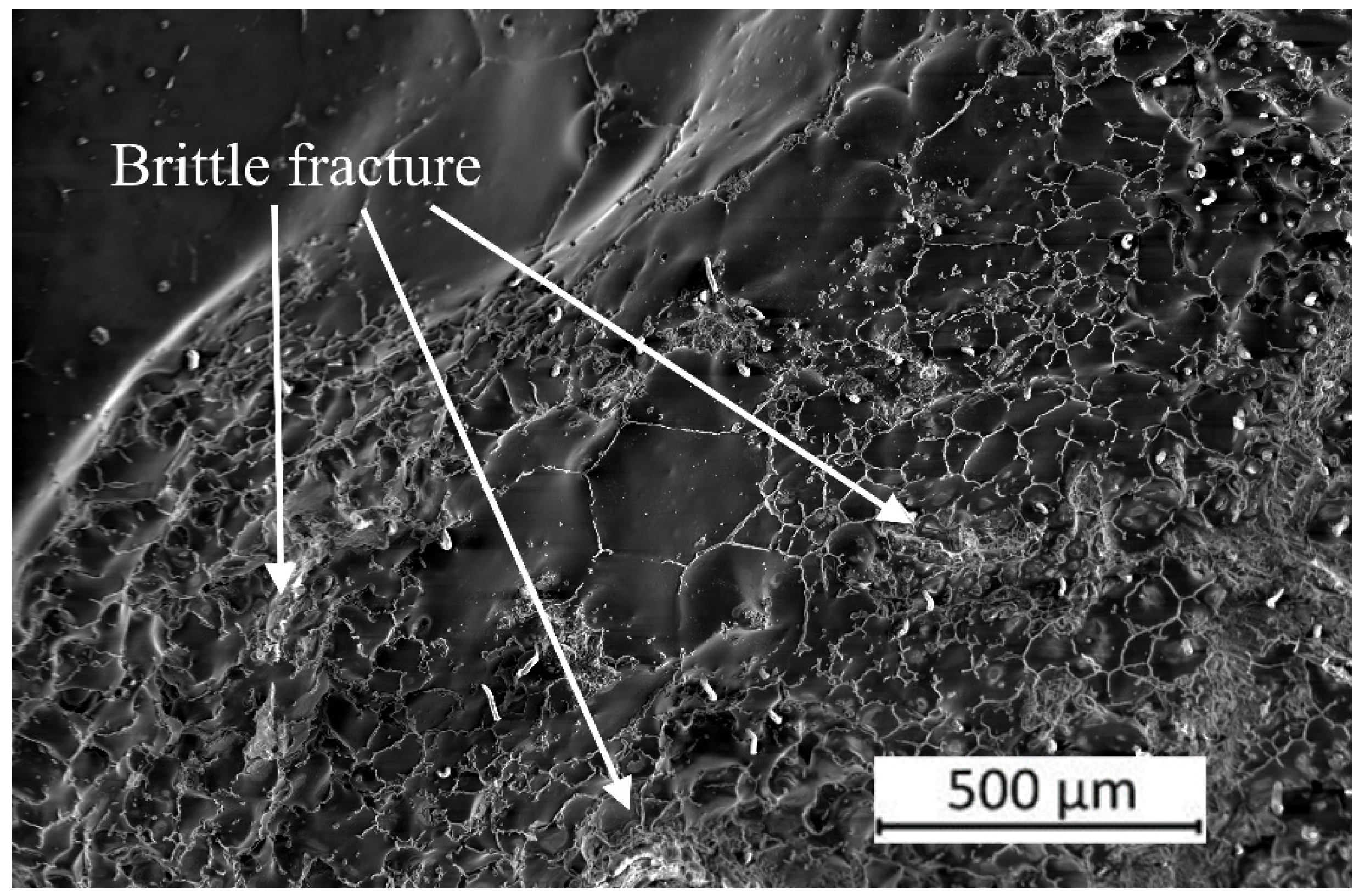
Figure 9 shows a micrograph of a sample annealed at 635 °C, part of which brittlely broke off under the influence of quenching stresses. This is due to the appearance of microcracks in the REM-rich intermetallic phase layers in the grain boundaries after quenching, which also confirms that the influence of the grain boundary wetting phase transition on the mechanical properties of the material can be significant.
Grain boundary wetting phase transformations have attracted the attention of researchers for quite a long time [94]. In particular, it was found that the transition from incomplete to complete wetting occurs at the grain boundaries with different energies [87] at different temperatures and pressures [95,100]. It is important to emphasize that the wetting phase at the grain boundary can not only be liquid, but also solid [101] or even amorphous [102]. Moreover, in the case of the pseudo-incomplete wetting of the grain boundaries or a deficiency in the wetting phase, the few nanometer-thick layers of the second phase, which are often called complexions, can form in the grain boundaries [90,103,104,105,106,107,108].
4. Conclusions
The grain boundary wetting phase transition in the ZEK100 magnesium-based alloy has been observed. The solidus temperature for the ZEK100 magnesium alloy was experimentally determined to be Ts = 529.5 ± 0.5 °C. The liquidus temperature for the ZEK100 magnesium alloy was experimentally determined to be Tl = 645 ± 5 °C. The first Mg/Mg grain boundaries completely wetted by the melt appear at 565 ± 5 °C. The last partially wetted grain boundaries disappear at 622.5 ± 2.5 °C. The influence of the wetting phase transition on the mechanical properties of the ZEK100 magnesium alloy has been observed. The presence of continous hard and brittle intergarnular layers strongly decreases the compression strength of the studied material.
Author Contributions
Conceptualization, B.S., A.S. and G.G.; methodology, G.D., A.S., N.K., V.O. and K.T.; validation, V.O., A.D., N.K., K.T. and G.G.; formal analysis, G.D. and V.O.; investigation, N.K., K.T. and G.D.; resources, G.G.; data curation, N.K., G.D. and A.S.; writing—original draft preparation, B.S. and A.S.; writing—review and editing, B.S. and G.G.; visualization, A.D.; supervision, B.S. and A.S.; project administration, A.D.; funding acquisition, A.S. All authors have read and agreed to the published version of the manuscript.
Funding
This research received no external funding.
Data Availability Statement
Not applicable.
Acknowledgments
The authors are incredibly grateful for the technical support of Michail Yuskov.
Conflicts of Interest
The authors declare no conflict of interest.
References
- Bryła, K.; Krystian, M.; Horky, J.; Mingler, B.; Mroczka, K.; Kurtyka, P.; Lityńska-Dobrzyńska, L. Improvement of Strength and Ductility of an EZ Magnesium Alloy by Applying Two Different ECAP Concepts to Processable Initial States. Mater. Sci. Eng. A 2018, 737, 318–327. [Google Scholar] [CrossRef]
- Bryła, K.; Morgiel, J.; Faryna, M.; Edalati, K.; Horita, Z. Effect of High-Pressure Torsion on Grain Refinement, Strength Enhancement and Uniform Ductility of EZ Magnesium Alloy. Mater. Lett. 2018, 212, 323–326. [Google Scholar] [CrossRef]
- Straumal, A.B.; Tsoy, K.V.; Mazilkin, I.A.; Nekrasov, A.N.; Bryła, K. Grain Boundary Wetting and Material Performance in an Industrial EZ33a Mg Cast Alloy. Arch. Metall. Mater. 2019, 64, 869–873. [Google Scholar] [CrossRef]
- Straumal, A.; Mazilkin, I.; Tzoy, K.; Straumal, B.; Bryła, K.; Baranchikov, A.; Eggeler, G. Bulk and Surface Low Temperature Phase Transitions in the Mg-Alloy EZ33A. Metals 2020, 10, 1127. [Google Scholar] [CrossRef]
- Trang, T.T.T.; Zhang, J.H.; Kim, J.H.; Zargaran, A.; Hwang, J.H.; Suh, B.C.; Kim, N.J. Designing a Magnesium Alloy with High Strength and High Formability. Nat. Commun. 2018, 9, 2522. [Google Scholar] [CrossRef]
- Oshida, Y. Magnesium Materials. From Mountain Bikes to Degradable Bone Grafts; De Gruyter Publishing: Berlin, Germany, 2021; p. 808. [Google Scholar] [CrossRef]
- Atrens, A.; Dietzel, W.; Srinivasan, P.B.; Winzer, N.; Kannan, M.B. Chapter 9: Stress Corrosion Cracking (SCC) of Magnesium Alloys. In Stress Corrosion Cracking: Theory and Practice; Woodhead Publishing: Cambridge, UK, 2011; pp. 341–380. [Google Scholar] [CrossRef]
- Martinez, D.C.; Dobkowska, A.; Marek, R.; Cwieka, H.; Jaroszewicz, J.; Plocinski, T.P.; Donik, C.; Helmholz, H.; Luthringer-Feyerabend, B.; Zeller-Plumhoff, B.; et al. In Vitro and In Vivo Degradation Behavior of Mg-0.45Zn-0.45Ca (ZX00) Screws for Orthopedic Applications. Bioact. Mat. 2023, 28, 132–154. [Google Scholar] [CrossRef] [PubMed]
- Wang, H.; Sun, X.; Kurukuri, S.; Worswick, M.J.; Li, D.Y.; Peng, Y.H.; Wu, P.D. The Strain Rate Sensitive and Anisotropic Behavior of Rare-Earth Magnesium Alloy ZEK100 Sheet. J. Magn. Alloys 2023, 11, 882–891. [Google Scholar] [CrossRef]
- Al-Samman, T.; Li, X. Sheet Texture Modification in Magnesium-Based Alloys by Selective Rare Earth Alloying. Mater. Sci. Eng. A 2011, 528, 3809–3822. [Google Scholar] [CrossRef]
- Patel, M.; Paudel, Y.; Mujahid, S.; Rhee, H.; El Kadiri, H. Self-Consistent Crystal Plasticity Modeling of Slip-Twin Interactions in Mg Alloys. Crystals 2023, 13, 653. [Google Scholar] [CrossRef]
- Ishiguro, Y.; Huang, X.; Tsukada, Y.; Koyama, T.; Chino, Y. Effect of Bending and Tension Deformation on the Texture Evolution and Stretch Formability of Mg–Zn–RE–Zr Alloy. Int. J. Miner. Metall. Mater. 2022, 29, 1334. [Google Scholar] [CrossRef]
- Griffits, D.; Davis, B.; Robson, J.D. The Influence of Strain Path on Rare Earth Recrystallization Textures in a Magnesium-Zinc-Rare Earth Alloy. Metal. Mater. Trans. A 2018, 49, 321–332. [Google Scholar] [CrossRef]
- Habib, S.A.; Khan, A.S.; Gnäupel-Herold, T.; Lloyd, J.T.; Schoenfeld, S.E. Anisotropy, Tension-Compression Asymmetry and Texture Evolution of a Rare-Earth-Containing Magnesium Alloy Sheet, ZEK100, at Different Strain Rates and Temperatures: Experiments and Modeling. Int. J. Plast. 2017, 95, 163–190. [Google Scholar] [CrossRef]
- Becker, R.; Lloyd, J.T. A Reduced-Order Crystal Model for HCP Metals: Application to Mg. Mech. Mater. 2016, 98, 98–110. [Google Scholar] [CrossRef]
- Omer, K.; Butcher, C.; Worswick, M. Characterization of Heat Transfer Coefficient for Non-isothermal Elevated Temperature Forming of Metal Alloys. Int. J. Mater. Form. 2020, 13, 177–201. [Google Scholar] [CrossRef]
- Hadadzadeh, A.; Wells, M.A.; Javaid, A. Warm and Hot Deformation Behavior of As-delivered ZEK100 Magnesium Alloy. Exp. Mech. 2016, 56, 259–271. [Google Scholar] [CrossRef]
- Abedini, A.; Butcher, C.; Worswick, M.J. Experimental Fracture Characterisation of an Anisotropic Magnesium Alloy Sheet in Proportional and Non-proportional Loading Conditions. Int. J. Solids Struct. 2018, 144–145, 1–19. [Google Scholar] [CrossRef]
- Abedini, A.; Butcher, C.; Worswick, M.J. Fracture Characterization of Rolled Sheet Alloys in Shear Loading: Studies of Specimen Geometry, Anisotropy, and Rate Sensitivity. Exp. Mech. 2017, 57, 75–88. [Google Scholar] [CrossRef]
- Ray, A.K.; Wilkinson, D.S. The Effect of Microstructure on Damage and Fracture in AZ31B and ZEK100 Magnesium Alloys. Mater. Sci. Eng. A 2016, 658, 33–41. [Google Scholar] [CrossRef]
- Li, Q.; Yea, W.; Gaoa, H.; Gao, L. Improving the Corrosion Resistance of ZEK100 Magnesium Alloy by Combining High-pressure Torsion Technology with Hydroxyapatite Coating. Mater. Des. 2019, 181, 107933. [Google Scholar] [CrossRef]
- Min, J.; Hector, L.G., Jr.; Lin, J.; Carter, J.T.; Sachdev, A.K. Spatio-temporal Characteristics of Propagative Plastic Instabilities in a Rare Earth Containing Magnesium Alloy. Int. J. Plast. 2014, 57, 52–76. [Google Scholar] [CrossRef]
- Kamrani, S.; Fleck, C. Effects of Calcium and Rare-earth Elements on the Microstructure and Tension–Compression Yield Asymmetry of ZEK100 Alloy. Mater. Sci. Eng. A 2014, 618, 238–243. [Google Scholar] [CrossRef]
- Ertürk, S.; Brocks, W.; Bohlen, J.; Letzig, D.; Steglich, D. A Constitutive Law for the Thermo-mechanical Modelling of Magnesium Alloy Extrusion. Int. J. Mater. Form. 2012, 5, 325–339. [Google Scholar] [CrossRef]
- Dobroñ, P.; Chmelík, F.; Parfenenko, K.; Letzig, D.; Bohlen, J. On the Effect of the Extrusion Speed on Microstructure and Plastic Deformation of ZE10 and ZEK100 Magnesium Alloys—An Acoustic Emission Study. Acta Phys. Pol. 2012, 122, 593–596. [Google Scholar] [CrossRef]
- Javaid, A.; Czerwinski, F. Effect of Hot Rolling on Microstructure and Properties of the ZEK100 Alloy. J. Magn. Alloys 2019, 7, 27–37. [Google Scholar] [CrossRef]
- Boba, M.; Butcher, C.; Panahi, N.; Worswick, M.J.; Mishra, R.K.; Carter, J.T. Warm Forming Limits of Rare Earth-magnesium Alloy ZEK100 Sheet. Int. J. Mater. Form. 2017, 10, 181–191. [Google Scholar] [CrossRef]
- Roostaei, A.A.; Ling, Y.; Jahed, H.; Glinka, G. Applications of Neuber’s and Glinka’s Notch Plasticity Correction Rules to Asymmetric Magnesium Alloys Under Cyclic Load. Theor. Appl. Fract. Mech. 2020, 105, 102431. [Google Scholar] [CrossRef]
- Ling, Y.; Roostaei, A.A.; Glinka, G.; Jahed, H. Fatigue of ZEK100-F Magnesium Alloy: Characterisation and Modelling. Int. J. Fatigue 2019, 125, 179–186. [Google Scholar] [CrossRef]
- Chen, G.; Ren, J.; Gao, H.; Cui, Y.; Chen, X. Pseudoelastic and Corrosion Behaviors of Mg ZEK100 Alloy under Cyclic Loading. Int. J. Fatigue 2017, 103, 466–477. [Google Scholar] [CrossRef]
- Mokdad, F.; Chen, D.L. Cyclic Deformation and Anelastic Behavior of ZEK100 Magnesium Alloy: Effect of Strain Ratio. Mater. Sci. Eng. A 2015, 640, 243–258. [Google Scholar] [CrossRef]
- Mokdad, F.; Chen, D.L. Strain-controlled Low Cycle Fatigue Properties of a Rare-earth Containing ZEK100 Magnesium Alloy. Mater. Des. 2015, 67, 436–447. [Google Scholar] [CrossRef]
- Min, J.; Lin, J. Anelastic Behavior and Phenomenological Modeling of Mg ZEK100-O Alloy Sheet under Cyclic Tensile Loading–Unloading. Mater. Sci. Eng. A 2013, 561, 174–182. [Google Scholar] [CrossRef]
- Aslam, I.; Li, B.; McClelland, Z.; Horstemeyer, S.J.; Maa, Q.; Wang, P.T.; Horstemeyer, M.F. Three-point Bending Behavior of a ZEK100 Mg Alloy at Room Temperature. Mater. Sci. Eng. A 2014, 590, 168–173. [Google Scholar] [CrossRef]
- Noder, J.; Abedini, A.; Butcher, C. Evaluation of the VDA 238–100 Tight Radius Bend Test for Plane Strain Fracture Characterization of Automotive Sheet Metals. Exp. Mech. 2020, 60, 787–800. [Google Scholar] [CrossRef]
- Paudel, Y.R.; Indeck, J.; Hazeli, K.; Priddy, M.W.; Inal, K.; Rhee, H.; Barrett, C.D.; Whittington, W.R.; Limmer, K.R.; El Kadiri, H. Characterization and Modeling of {1012} Twin Banding in Magnesium. Acta Mater. 2020, 183, 438–451. [Google Scholar] [CrossRef]
- Min, J.; Lin, J.; Li, J. Forming Limits of Mg alloy ZEK100 Sheet in Preform Annealing Process. Mater. Des. 2014, 53, 947–953. [Google Scholar] [CrossRef]
- Min, J.; Hector, L.G., Jr.; Lin, J.; Carter, J.T. Analytical Method for Forming Limit Diagram Prediction with Application to a Magnesium ZEK100-O Alloy. J. Mater. Eng. Perform. 2013, 22, 3324–3336. [Google Scholar] [CrossRef]
- Antoniswamy, A.R.; Carpenter, A.J.; Carter, J.T.; Hector, L.G., Jr.; Taleff, E.M. Forming-Limit Diagrams for Magnesium AZ31B and ZEK100 Alloy Sheets at Elevated Temperatures. J. Mater. Eng. Perform. 2013, 22, 3389–3397. [Google Scholar] [CrossRef]
- Bong, H.J.; Hu, X.; Sun, X.; Ren, Y. Temperature-Dependent Constitutive Modeling of a Magnesium Alloy ZEK100 Sheet Using Crystal Plasticity Models Combined with In Situ High-Energy X-ray Diffraction Experiment. J. Magnes. Alloys 2022, 10, 2801–2816. [Google Scholar] [CrossRef]
- Sun, X.; Zhang, B.; Jiang, Y.; Wu, P.; Wang, H. Multi-Island Genetic-Algorithm-Based Approach to Uniquely Calibrate Polycrystal Plasticity Models for Magnesium Alloys. JOM 2021, 73, 1395–1403. [Google Scholar] [CrossRef]
- Bong, H.J.; Hu, X.; Sun, X.; Ren, Y. Mechanism-Based Constitutive Modeling of ZEK100 Magnesium Alloy with Crystal Plasticity and In-Situ HEXRD Experiment. Int. J. Plast. 2019, 113, 35–51. [Google Scholar] [CrossRef]
- Abedini, A.; Butcher, C.; Worswick, M.J. Application of an Evolving Non-Associative Anisotropic-Asymmetric Plasticity Model for a Rare-Earth Magnesium Alloy. Metals 2018, 8, 1013. [Google Scholar] [CrossRef]
- Zhang, K.; Badreddine, H.; Saanouni, K. Thermodynamically-Consistent Constitutive Modeling of Hardening Asymmetry Including Isotropic Ductile Damage for Mg Alloys. Eur. J. Mech. A Solids 2019, 73, 169–180. [Google Scholar] [CrossRef]
- Abedini, A.; Butcher, C.; Nemcko, M.J.; Kurukuri, S.; Worswick, M.J. Constitutive Characterization of a Rare-Earth Magnesium Alloy Sheet (ZEK100-O) in Shear Loading: Studies of Anisotropy and Rate Sensitivity. Int. J. Mech. Sci. 2017, 128–129, 54–69. [Google Scholar] [CrossRef]
- Muhammad, W.; Mohammadi, M.; Kang, J.; Mishra, R.K.; Inal, K. An Elasto-Plastic Constitutive Model for Evolving Asymmetric/anisotropic Hardening Behavior of AZ31B and ZEK100 Magnesium Alloy Sheets Considering Monotonic and Reverse Loading Paths. Int. J. Plast. 2015, 70, 30–59. [Google Scholar] [CrossRef]
- Sharma, S.K.; Saxena, K.K.; Malik, V.; Mohammed, K.A.; Prakash, C.; Buddhi, D.; Dixit, S. Significance of Alloying Elements on the Mechanical Characteristics of Mg-Based Materials for Biomedical Applications. Crystals 2022, 12, 1138. [Google Scholar] [CrossRef]
- Gao, H.; Zhang, M.; Zhao, J.; Gao, L.; Li, M. In Vitro and in Vivo Degradation and Mechanical Properties of ZEK100 Magnesium Alloy Coated with Alginate, Chitosan and Mechano-growth Factor. Mater. Sci. Eng. C 2016, 63, 450–461. [Google Scholar] [CrossRef]
- Grillo, C.A.; Alvarez, F.; Fernández Lorenzo de Mele, M.A. Degradation of Bioabsorbable Mg-Based Alloys: Assessment of the Effects of Insoluble Corrosion Products and Joint Effects of Alloying Components on Mammalian Cells. Mater. Sci. Eng. C 2016, 58, 372–380. [Google Scholar] [CrossRef]
- Reifenrath, J.; Marten, A.-K.; Angrisani, N.; Eifler, R.; Weizbauer, A. In Vitro and In Vivo Corrosion of the Novel Magnesium Alloy Mg–La–Nd–Zr: Influence of the Measurement Technique and in vivo Implant Location. Biomed. Mater. 2015, 10, 045021. [Google Scholar] [CrossRef]
- Zhao, J.; Gao, L.-L.; Gao, H.; Yuan, X.; Chen, X. Biodegradable Behaviour and Fatigue Life of ZEK100 Magnesium Alloy in Simulated Physiological Environment. Fatigue Fract. Eng. Mater. Struct. 2015, 38, 904–913. [Google Scholar] [CrossRef]
- Bondarenko, A.; Angrisani, N.; Meyer-Lindenberg, A.; Seitz, J.M.; Waizy, H.; Reifenrath, J. Magnesium-based Bone Implants: Immunohistochemical Inalysis of Peri-implant Osteogenesis by Evaluation of Osteopontin and Osteocalcin Expression. J. Biomed. Mater. Res. Part A 2014, 102, 1449–1457. [Google Scholar] [CrossRef]
- Weizbauer, A.; Modrejewski, C.; Behrens, S.; Klein, H.; Helmecke, P.; Seitz, J.-M.; Windhagen, H.; Möhwald, K.; Reifenrath, J.; Waizy, H. Comparative in vitro Study and Biomechanical Testing of Two Different Magnesium Alloys. J. Biomater. Appl. 2014, 28, 1264–1273. [Google Scholar] [CrossRef] [PubMed]
- Dziuba, D.; Meyer-Lindenberg, A.; Seitz, J.M.; Waizy, H.; Angrisani, N.; Reifenrath, J. Long-term in vivo Degradation Behaviour and Biocompatibility of the Magnesium Alloy ZEK100 for use as a Biodegradable Bone Implant. Acta Biomater. 2013, 9, 8548–8560. [Google Scholar] [CrossRef]
- Reifenrath, J.; Angrisani, N.; Erdmann, N.; Lucas, A.; Waizy, H.; Seitz, J.M.; Bondarenko, A.; Meyer-Lindenberg, A. Degrading Magnesium Screws ZEK100: Biomechanical Testing, Degradation Analysis and Soft-tissue Biocompatibility in a Rabbit Model. Biomed. Mater. 2013, 8, 045012. [Google Scholar] [CrossRef]
- Bauer, M.; Biskup, C.; Schilling, T.; Haverich, A.; Bach, F.W.; Maier, H.J.; Hassel, T. Influence of Shot Peening on Surface Rougness and in vitro Load Cycles of Magnesium Alloys. Biomed. Tech. 2013, 58, 4060. [Google Scholar] [CrossRef]
- Weidling, M.; Besdo, S.; Schilling, T.; Bauer, M.; Hassel, T.; Haverich, A.; Wriggers, P. Finite Element Simulation of Myocardial Stabilising Structures and Development of New Designs. Biomed. Tech. 2013, 58, 4061. [Google Scholar] [CrossRef]
- Schulman, J.; Meyer-Lindenberg, A.; Goblet, F.; Bormann, D.; Stiller, W.; Seifert, H. Phantomuntersuchungen an einem Hochauflösenden CT zur Ex-vivo-Darstellung von Degradierbaren Magnesiumimplantaten und Simulierten Periimplantären Knochenschichten in Kaninchentibiae. Fortschr. Röntgenstr. 2012, 184, 455–460. [Google Scholar] [CrossRef]
- Huehnerschulte, T.A.; Angrisani, N.; Rittershaus, D.; Bormann, D.; Windhagen, H.; Meyer-Lindenberg, A. In Vivo Corrosion of Two Novel Magnesium Alloys ZEK100 and AX30 and Their Mechanical Suitability as Biodegradable Implants. Materials 2011, 4, 1144–1167. [Google Scholar] [CrossRef] [PubMed]
- Huehnerschulte, T.A.; Reifenrath, J.; von Rechenberg, B.; Dziuba, D.; Seitz, J.M.; Bormann, D.; Windhagen, H.; Meyer-Lindenberg, A. In Vivo Assessment of the Host Reactions to the Biodegradation of the Two Novel Magnesium Alloys ZEK100 and AX30 in an Animal Model. BioMed. Eng. OnLine 2012, 11, 14. [Google Scholar] [CrossRef]
- Seitz, J.-M.; Utermöhlen, D.; Wulf, E.; Klose, C.; Bach, F.-W. The Manufacture of Resorbable Suture Material from Magnesium—Drawing and Stranding of Thin Wires. Adv. Eng. Mater. 2011, 13, 1087–1095. [Google Scholar] [CrossRef]
- Seitz, J.-M.; Wulf, E.; Freytag, P.; Bormann, D.; Bach, F.-W. The Manufacture of Resorbable Suture Material from Magnesium. Adv. Eng. Mater. 2010, 12, 1099–1105. [Google Scholar] [CrossRef]
- Zaghloul, B.; Kish, J.R. Corrosion Inhibition of Mg Alloy ZEK100 Sheet Metal by Dissolved Lithium Carbonate. J. Electrochem. Soc. 2021, 168, 081507. [Google Scholar] [CrossRef]
- Brady, M.P.; Rother, G.; Frith, M.G.; Ievlev, A.E.; Leonard, D.N.; Littrell, K.C.; Cakmak, E.; MeyerIII, H.M.; Anovitz, L.M.; Davis, B. Temporal Evolution of Corrosion Film Nano-Porosity and Magnesium Alloy Hydrogen Penetration in NaCl Solution. J. Electrochem. Soc. 2020, 167, 131513. [Google Scholar] [CrossRef]
- Brady, M.P.; Leonard, D.N.; McNally, E.A.; Kish, J.R.; Meyer, H.M.; Cakmak, E.; Davis, B. Magnesium Alloy Effects on Plasma Electrolytic Oxidation Electro-Ceramic and Electro-Coat Formation and Corrosion Resistance. J. Electrochem. Soc. 2019, 166, C492–C508. [Google Scholar] [CrossRef]
- Binns, W.J.; Zargarzadah, F.; Dehnavi, V.; Chen, J.; Noël, J.J.; Shoesmith, D.W. Physical and Electrochemical Evidence for the Role of a Mg Hydride Species in Mg Alloy Corrosion. Corrosion 2019, 75, 58–68. [Google Scholar] [CrossRef] [PubMed]
- Brady, M.P.; Leonard, D.N.; Meyer III, H.M.; Thomson, J.K.; Unocic, K.A.; Elsentriecy, H.H.; Song, G.-L.; Kitchen, K.; Davis, B. Advanced Characterization Study of Commercial Conversion and Electrocoating Structures on Magnesium Alloys AZ31B and ZE10A. Surf. Coat. Technol. 2016, 294, 164–176. [Google Scholar] [CrossRef]
- Dauphin-Ducharme, P.; Binns, W.J.; Snowden, M.E.; Shoesmith, D.W.; Mauzeroll, J. Determination of the Local Corrosion Rate of Magnesium Alloys Using a Shear Force Mounted Scanning Microcapillary Method. Faraday Discuss. 2015, 180, 331–345. [Google Scholar] [CrossRef]
- Asmussen, R.M.; Binns, W.J.; Jakupi, P.; Shoesmith, D. The Influence of Microstructure on the Corrosion of Magnesium Alloy ZEK100. Corrosion 2015, 71, 242–254. [Google Scholar] [CrossRef]
- Waizy, H.; Weizbauer, A.; Modrejewski, C.; Witte, F.; Windhagen, H.; Lucas, A.; Kieke, M.; Denken, B.; Behrens, P.; Meyer-Lindenberg, A. In Vitro Corrosion of ZEK100 Plates in Hank’s Balanced Salt Solution. BioMed. Eng. OnLine 2012, 11, 12. [Google Scholar] [CrossRef]
- Bauer, M.; Hassel, T.; Biskup, C.; Hartung, D.; Schilling, T.; Weidling, M.; Wriggers, P.; Wacker, F.; Bach, F.W.; Haverich, A. Geometric Adaption of Resorbable Myocardial Stabilizing Structures Based on the Magnesium Alloys LA63 and ZEK100 for the Support of Myocardial Grafts on the Left Ventricle. Biomed. Eng. 2012, 57, 22–25. [Google Scholar] [CrossRef]
- Gao, H.; Ye, W.; Zhang, Z.; Gao, L. Ratcheting Behavior of ZEK100 Magnesium Alloy with Various Loading Conditions and Different Immersing Time. J. Mater. Res. 2017, 32, 2143–2152. [Google Scholar] [CrossRef]
- Krüger, R.; Seitz, J.-M.; Ewald, A.; Bach, F.-W.; Groll, J. Strong and Tough Magnesium Wire Reinforced Phosphate Cement Composites for Load-bearing Bone Replacement. J. Mech. Behav. Biomed. Mater. 2013, 20, 36–44. [Google Scholar] [CrossRef]
- Peng, H.; Chen, D.L.; Bai, X.F.; Wang, P.Q.; Li, D.Y.; Jiang, X.Q. Microstructure and Mechanical Properties of Mg-to-Al Dissimilar Welded Joints with an Ag Interlayer using Ultrasonic Spot Welding. J. Magn. Alloys 2020, 8, 552–563. [Google Scholar] [CrossRef]
- Macwan, A.; Chen, D.L. Ultrasonic Spot Welding of a Rare-Earth Containing ZEK100 Magnesium Alloy: Effect of Welding Energy. Metal. Mater Trans. A 2016, 47, 1686–1697. [Google Scholar] [CrossRef]
- Chen, Y.; Chen, J.; Amirkhiz, B.S.; Worswick, M.J.; Gerlich, A.P. Microstructures and Properties of Mg alloy/DP600 Steel Dissimilar Refill Friction Stir Spot Welds. Sci. Technol. Weld. Join. 2015, 20, 494–501. [Google Scholar] [CrossRef]
- Rodriguez, R.I.; Jordon, J.B.; Rao, H.M.; Badarinarayan, H.; Yuan, W.; ElKadiri, H.; Allison, P.G. Microstructure, Texture, and Mechanical Properties of Friction Stir Spot Welded Rare-Earth Containing ZEK100 Magnesium Alloy Sheets. Mater. Sci. Eng. A 2014, 618, 637–644. [Google Scholar] [CrossRef]
- Peng, H.; Chen, D.L.; Bai, X.F.; She, X.W.; Li, D.Y.; Jiang, X.Q. Ultrasonic Spot Welding of Magnesium-to-Aluminum Alloys with a Copper Interlayer: Microstructural Evolution and Tensile Properties. J. Manuf. Proc. 2019, 37, 91–100. [Google Scholar] [CrossRef]
- Peng, H.; Jiang, X.; Bai, X.; Li, D.; Chen, D. Microstructure and Mechanical Properties of Ultrasonic Spot Welded Mg/Al Alloy Dissimilar Joints. Metals 2018, 8, 229. [Google Scholar] [CrossRef]
- Macwan, A.; Chen, D.L. Ultrasonic Spot Welding of Rare-Earth Containing ZEK100 Magnesium Alloy to 5754 Aluminum Alloy. Mater. Sci. Eng. A 2016, 666, 139–148. [Google Scholar] [CrossRef]
- Kuang, J.; Li, X.; Ye, X.; Tang, J.; Liu, H.; Wang, J.; Tang, G. Microstructure and Texture Evolution of Magnesium Alloys During Electropulse Treatment. Metall. Mater. Trans. A 2015, 46, 1789–1804. [Google Scholar] [CrossRef]
- Yang, J.; Yu, Z.; Li, Y.; Zhang, H.; Zhou, N. Laser Welding/Brazing of 5182 Aluminium Alloy to ZEK100 Magnesium Alloy Using a Nickel Interlayer. Sci. Technol. Weld. Join. 2018, 23, 543–550. [Google Scholar] [CrossRef]
- Yang, J.; Su, J.H.; Yu, Z.S.; Zhang, G.Z.; Lin, S.B.; Li, Y.L.; Zhou, N.Y. Influence of Ni Interlayer Width on Interfacial Reactions and Mechanical Properties in Laser Welding/Brazing of Al/Mg Lap Joint. Sci. Technol. Weld. Join. 2019, 25, 37–44. [Google Scholar] [CrossRef]
- Cahn, J.W. Critical Point Wetting. J. Chem. Phys. 1977, 66, 3667. [Google Scholar] [CrossRef]
- Ebner, C.; Saam, W.F. New Phase-Transition Phenomena in Thin Argon Films. Phys. Rev. Lett. 1977, 38, 1486. [Google Scholar] [CrossRef]
- Straumal, B.B.; Polyakov, S.A.; Bischoff, E.; Gust, W.; Mittemeijer, E.J. Faceting of Σ3 and Σ9 grain boundaries in copper. Interface Sci. 2001, 9, 287–292. [Google Scholar] [CrossRef]
- Maksimova, E.L.; Shvindlerman, L.S.; Straumal, B.B. Transformation of Σ17 special tilt boundaries to general boundaries in tin. Acta Metall. 1988, 36, 1573–1583. [Google Scholar] [CrossRef]
- Laporte, D.; Watson, E.B. Experimental and Theoretical Constraints on Melt Distribution in Crustal Sources: The Effect of Crystalline Anisotropy on Melt Interconnectivity. Chem. Geol. 1995, 124, 161–184. [Google Scholar] [CrossRef]
- Noskovich, O.I.; Rabkin, E.I.; Semenov, V.N.; Straumal, B.B.; Shvindlerman, L.S. Wetting and premelting phase transitions in 38° [100] tilt grain boundaries in (Fe–12at.%Si) Zn alloy in the vicinity of the A2–B2 bulk ordering in Fe–12at.%Si alloy. Acta Metall. Mater. 1991, 39, 3091–3098. [Google Scholar] [CrossRef]
- Chang, L.-S.; Rabkin, E.; Straumal, B.B.; Hoffmann, S.; Baretzky, B.; Gust, W. Grain boundary segregation in the Cu–Bi system. Defect Diff. Forum 1998, 156, 135–146. [Google Scholar] [CrossRef]
- Ross, D.; Bonn, D.; Meunier, J. Observation of Short-Range Critical Wetting. Nature 1999, 400, 737–739. [Google Scholar] [CrossRef]
- Straumal, B.B.; Gust, W.; Watanabe, T. Tie lines of the grain boundary wetting phase transition in the Zn-rich part of the Zn–Sn phase diagram. Mater. Sci. Forum 1999, 294–296, 411–414. [Google Scholar] [CrossRef]
- Rabkin, E.I.; Shvindlerman, L.S.; Straumal, B.B. Grain Boundaries: Phase Transitions and Critical Phenomena. Int. J. Mod. Phys. B 1991, 5, 2989–3028. [Google Scholar] [CrossRef]
- German, R.M.; Suri, P.; Park, S.J. Review: Liquid Phase Sintering. J. Mater. Sci. 2009, 44, 1–39. [Google Scholar] [CrossRef]
- Straumal, B.; Rabkin, E.; Lojkowski, W.; Gust, W.; Shvindlerman, L.S. Pressure influence on the grain boundary wetting phase transition in Fe–Si alloys. Acta Mater. 1997, 45, 1931–1940. [Google Scholar] [CrossRef]
- Straumal, A.B.; Mazilkin, I.A.; Tsoi, K.V.; Baretzky, B.; Straumal, B.B. “Wetting” Phase Transitions by the Second Solid Phase for Linear Defects (Grain Boundary Triple Junctions). JETP Lett. 2020, 112, 257–261. [Google Scholar] [CrossRef]
- Straumal, A.B.; Bokstein, B.S.; Petelin, A.L.; Straumal, B.B.; Baretzky, B.; Rodin, A.O.; Nekrasov, A.N. Apparently Complete Grain Boundary Wetting in Cu–In Alloys. J. Mater. Sci. 2012, 47, 8336–8343. [Google Scholar] [CrossRef]
- Jandaghi, M.R.; Pouraliakbar, H.; Hong, S.I.; Pavese, M. Grain Boundary Transition Associated Intergranular Failure Analysis at TMAZ/SZ Interface of Dissimilar AA7475-AA2198 Joints by Friction Stir Welding. Mater. Lett. 2020, 280, 128557. [Google Scholar] [CrossRef]
- Jandaghi, M.R.; Pouraliakbar, H.; Saboori, A.; Hong, S.I.; Pavese, M. Comparative Insight into the Interfacial Phase Evolutions during Solution Treatment of Dissimilar Friction Stir Welded AA2198-AA7475 and AA2198-AA6013 Aluminum Sheets. Materials 2021, 14, 1290. [Google Scholar] [CrossRef] [PubMed]
- Molodov, D.A.; Straumal, B.B.; Shvindlerman, L.S. The Effect of Pressure on Migration of the [001] Tilt Grain Boundaries in the Tin Bicrystals. Scripta metall. 1984, 18, 207–211. [Google Scholar] [CrossRef]
- Straumal, B.B.; Gornakova, A.S.; Kucheev, Y.O.; Baretzky, B.; Nekrasov, A.N. Grain Boundary Wetting by a Second Solid Phase in the Zr–Nb Alloys. J. Mater. Eng. Perform. 2012, 21, 721–724. [Google Scholar] [CrossRef]
- Mazilkin, A.A.; Abrosimova, G.E.; Protasova, S.G.; Straumal, B.B.; Schütz, G.; Dobatkin, S.V.; Bakai, A.S. Transmission Electron Microscopy Investigation of Boundaries Between Amorphous “Grains” in Ni50Nb20Y30 Alloy. J. Mater. Sci. 2011, 46, 4336–4342. [Google Scholar] [CrossRef]
- Chang, L.-S.; Straumal, B.B.; Rabkin, E.; Gust, W.; Sommer, F. The Solidus Line of the Cu–Bi Phase Diagram. J. Phase Equil. 1997, 18, 128–135. [Google Scholar] [CrossRef]
- Straumal, B.B.; Mazilkin, A.A.; Protasova, S.G.; Dobatkin, S.V.; Rodin, A.O.; Baretzky, B.; Goll, D.; Schütz, G. Fe–C Nanograined Alloys Obtained by High Pressure Torsion: Structure and Magnetic Properties. Mater. Sci. Eng. A 2009, 503, 185–189. [Google Scholar] [CrossRef]
- Khisamov, R.K.; Kistanov, A.A.; Nazarov, K.S.; Shayakhmetov, R.U.; Korznikova, G.F.; Yumaguzin, Y.M.; Dmitriev, S.V.; Mulyukov, R.R. Work Function of Chemical Compounds of Aluminum-Magnesium System. IOP Conf. Ser. Mater. Sci. Eng. 2020, 1008, 012032. [Google Scholar] [CrossRef]
- Straumal, B.B.; Kilmametov, A.R.; Ivanisenko, Y.; Mazilkin, A.A.; Kogtenkova, O.A.; Kurmanaeva, L.; Korneva, A.; Zięba, P.; Baretzky, B. Phase Transitions Induced by Severe Plastic Deformation: Steady-State and Equifinality. Int. J. Mater. Res. 2015, 106, 657–664. [Google Scholar] [CrossRef]
- Khisamov, R.K.; Shayakhmetov, R.U.; Yumaguzin, Y.M.; Kistanov, A.A.; Korznikova, G.F.; Korznikova, E.A.; Nazarov, K.S.; Khalikova, G.R.; Timiryaev, R.R.; Mulyukov, R.R. Work Function, Sputtering Yield and Microhardness of an Al-Mg Metal-Matrix Nanostructured Composite Obtained with High-Pressure Torsion. Appl. Sci. 2023, 13, 5007. [Google Scholar] [CrossRef]
- Straumal, B.B.; Mazilkin, A.A.; Baretzky, B. Grain Boundary Complexions and Pseudopartial Wetting. Curr. Opin. Solid State Mater. Sci. 2016, 20, 247–256. [Google Scholar] [CrossRef]
Figure 1.
SEM (SE2) micrograph of the as-delivered sample and corresponding elemental maps for Mg, La, Ce, Nd, Zn, and Zr.
Figure 1.
SEM (SE2) micrograph of the as-delivered sample and corresponding elemental maps for Mg, La, Ce, Nd, Zn, and Zr.

Figure 2.
SEM micrographs of four ZEK100 samples after annealing at 565 °C for different times of (a) 0.5 h, (b) 1 h, (c) 2 h, and (d) 3 h.
Figure 2.
SEM micrographs of four ZEK100 samples after annealing at 565 °C for different times of (a) 0.5 h, (b) 1 h, (c) 2 h, and (d) 3 h.
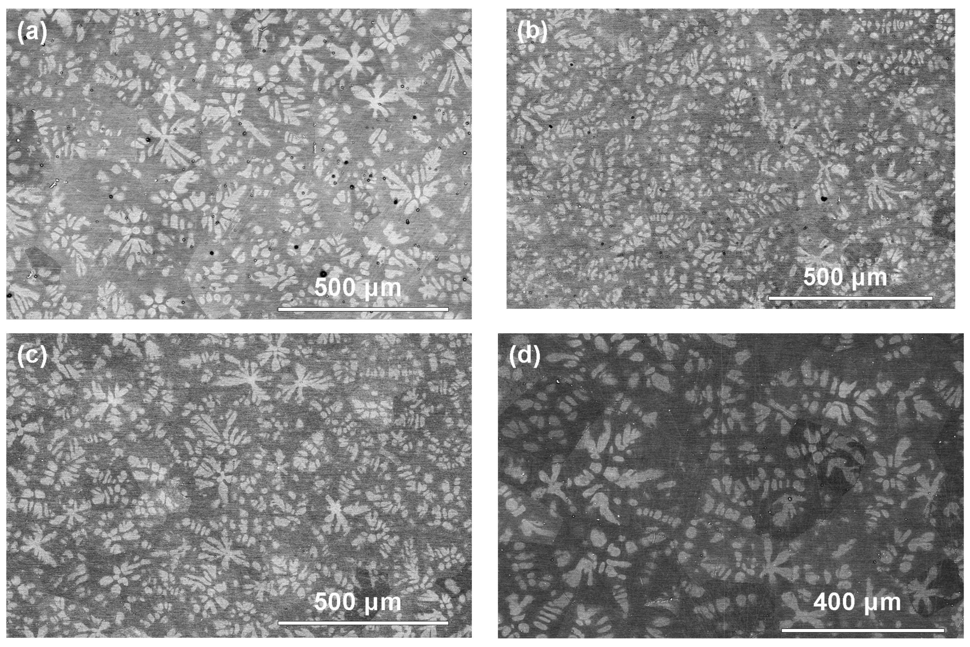
Figure 3.
SEM micrographs of ZEK100 samples after annealing at 640 °C (a) and 650 °C (b) for 2 h.
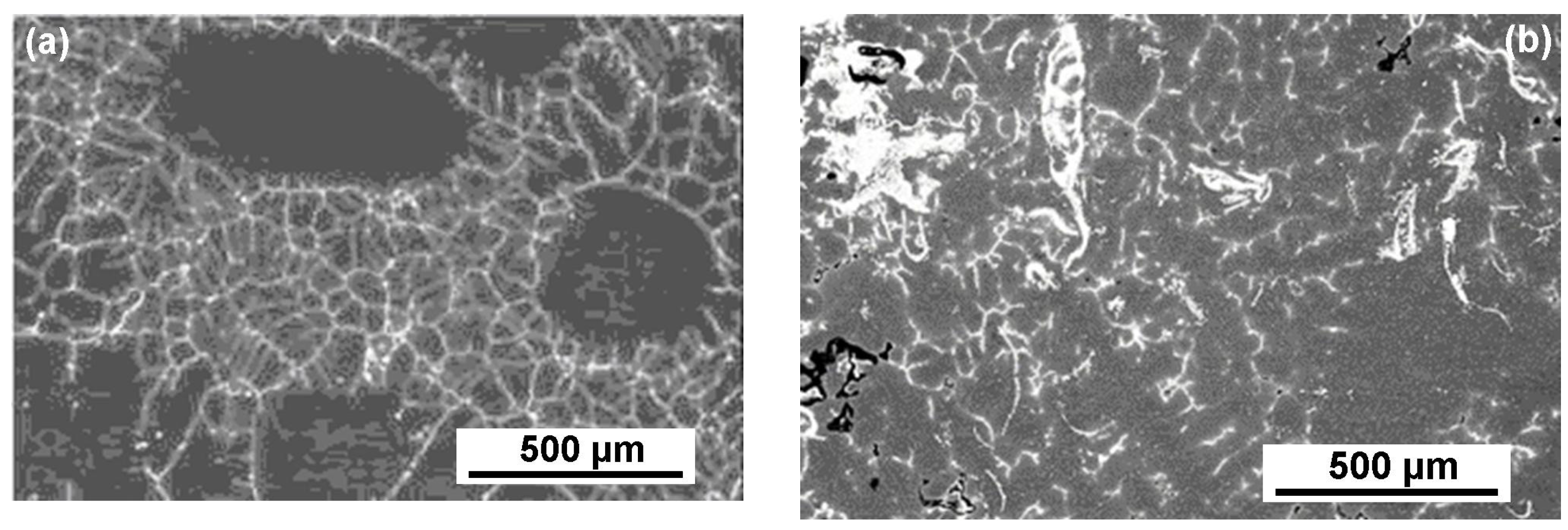
Figure 4.
SEM micrographs of ZEK100 samples in the initial (as-delivered) state and after annealing at 535, 545, 555, 565, 590, 600, and 610 °C for 2 h.
Figure 4.
SEM micrographs of ZEK100 samples in the initial (as-delivered) state and after annealing at 535, 545, 555, 565, 590, 600, and 610 °C for 2 h.

Figure 5.
Temperature dependence of the fraction of completely wetted Mg/Mg grain boundaries (squares). Red line is the guide for the eye.
Figure 5.
Temperature dependence of the fraction of completely wetted Mg/Mg grain boundaries (squares). Red line is the guide for the eye.

Figure 6.
The compression strain–stress curves for two samples annealed at 535 and 610 °C. The additional plots permit for calculating the yield strength parameter σ02.
Figure 6.
The compression strain–stress curves for two samples annealed at 535 and 610 °C. The additional plots permit for calculating the yield strength parameter σ02.

Figure 7.
The microhardness of the Mg-based matrix (black squares) in the samples annealed between 535 and 610 °C. The point at 25 °C corresponds to the ZEK100 alloy in the as-delivered state. The red line shows the mean value of the microhardness.
Figure 7.
The microhardness of the Mg-based matrix (black squares) in the samples annealed between 535 and 610 °C. The point at 25 °C corresponds to the ZEK100 alloy in the as-delivered state. The red line shows the mean value of the microhardness.
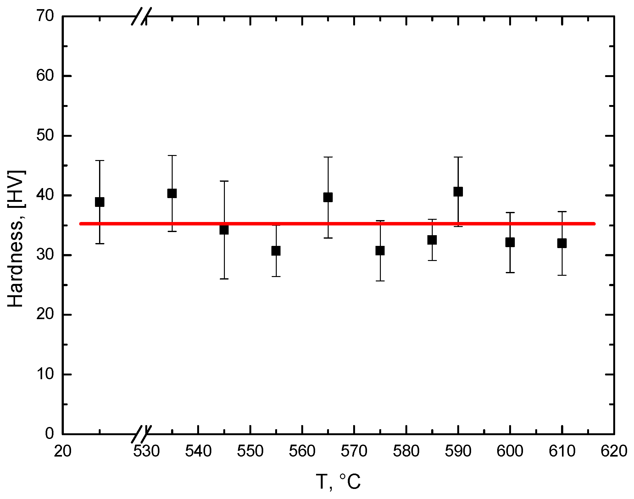
Figure 8.
Microstructures of the deformed initial sample ZEK100: (a) traces of sliding dislocations that passed between the particles of REM-enriched phase at the grain boundaries; (b) cracks in REM-enriched phase at the grain boundary.
Figure 8.
Microstructures of the deformed initial sample ZEK100: (a) traces of sliding dislocations that passed between the particles of REM-enriched phase at the grain boundaries; (b) cracks in REM-enriched phase at the grain boundary.
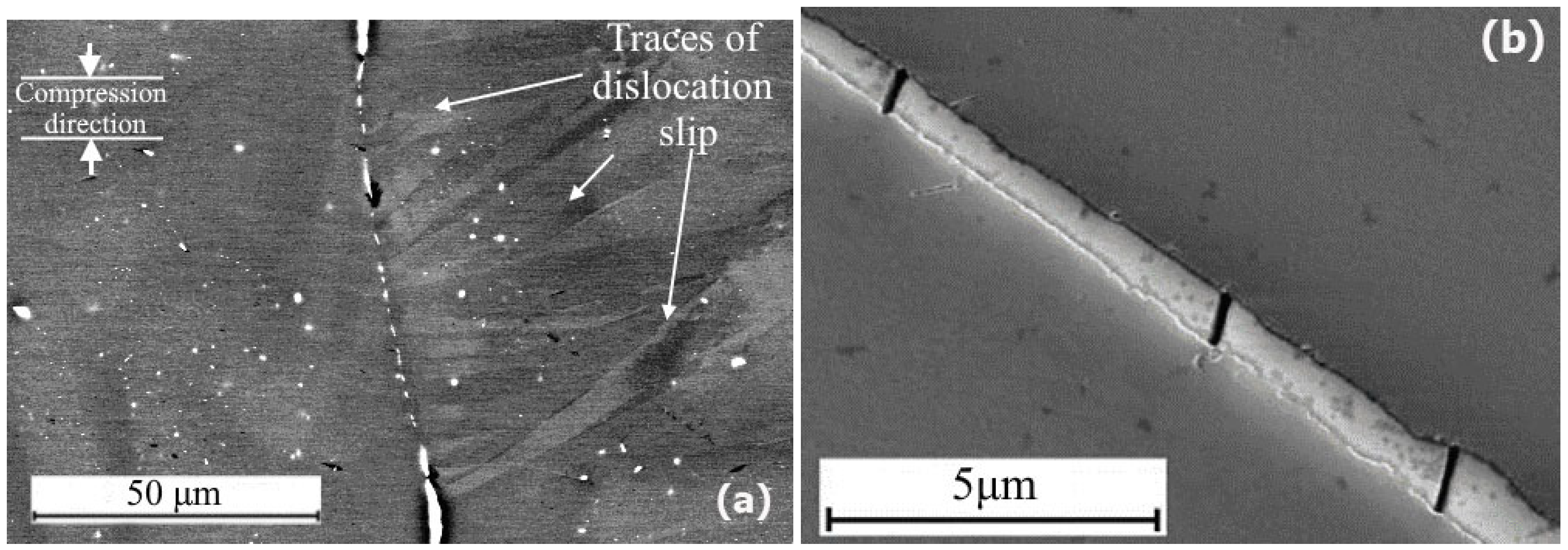
Figure 9.
Brittle fracture after annealing at 635 °C.
Disclaimer/Publisher’s Note: The statements, opinions and data contained in all publications are solely those of the individual author(s) and contributor(s) and not of MDPI and/or the editor(s). MDPI and/or the editor(s) disclaim responsibility for any injury to people or property resulting from any ideas, methods, instructions or products referred to in the content. |
© 2023 by the authors. Licensee MDPI, Basel, Switzerland. This article is an open access article distributed under the terms and conditions of the Creative Commons Attribution (CC BY) license (https://creativecommons.org/licenses/by/4.0/).
Share and Cite
MDPI and ACS Style
Straumal, B.; Khrapova, N.; Druzhinin, A.; Tsoy, K.; Davdian, G.; Orlov, V.; Gerstein, G.; Straumal, A. Grain Boundary Wetting Transition in the Mg-Based ZEK 100 Alloy. Crystals 2023, 13, 1538. https://doi.org/10.3390/cryst13111538
AMA Style
Straumal B, Khrapova N, Druzhinin A, Tsoy K, Davdian G, Orlov V, Gerstein G, Straumal A. Grain Boundary Wetting Transition in the Mg-Based ZEK 100 Alloy. Crystals. 2023; 13(11):1538. https://doi.org/10.3390/cryst13111538
Chicago/Turabian StyleStraumal, Boris, Natalya Khrapova, Aleksandr Druzhinin, Kristina Tsoy, Gregory Davdian, Valery Orlov, Gregory Gerstein, and Alexander Straumal. 2023. "Grain Boundary Wetting Transition in the Mg-Based ZEK 100 Alloy" Crystals 13, no. 11: 1538. https://doi.org/10.3390/cryst13111538
Note that from the first issue of 2016, this journal uses article numbers instead of page numbers. See further details here.