Article

Cladding of Carbon Steel with Stainless Steel Using Friction Stir Welding: Effect of Process Parameters on Microstructure and Mechanical Properties

by
Mahmoud S. I. Ahmed
1,
Mohamed M. Z. Ahmed
2,3,
Hussein M. Abd El-Aziz
1,
Mohamed I. A. Habba
4,
Ashraf F. Ismael
1,
Mohamed M. El-Sayed Seleman
3,
Ali Abd El-Aty
2,5,*,
Ali Alamry
2,
Bandar Alzahrani
2,
Kamel Touileb
2 and
Wael M. Fathy
1
1
Department of Mining and Petroleum Engineering, Faculty of Engineering, Al-Azhar University, Cairo 11651, Egypt
2
Department of Mechanical Engineering, College of Engineering at Al Kharj, Prince Sattam bin Abdulaziz University, Al Kharj 11942, Saudi Arabia
3
Department of Metallurgical and Materials Engineering, Faculty of Petroleum and Mining Engineering, Suez University, Suez 43512, Egypt
4
Mechanical Department, Faculty of Technology and Education, Suez University, Suez 43518, Egypt
5
Mechanical Engineering Department, Faculty of Engineering-Helwan, Helwan University, Cairo 11795, Egypt
*
Author to whom correspondence should be addressed.
Crystals 2023, 13(11), 1559; https://doi.org/10.3390/cryst13111559
Submission received: 13 September 2023 / Revised: 9 October 2023 / Accepted: 17 October 2023 / Published: 1 November 2023
(This article belongs to the Special Issue Modern Technologies in the Manufacturing of Metal Matrix Composites)

Abstract

:
The aim of this study is to investigate friction stir welding (FSW) to join A304 austenitic stainless steel and low carbon steel A283 Gr. C in-lap configuration to clad the carbon steel with highly corrosion-resistant stainless steel. Thus, a wide range of FSW parameters were investigated such as FSW tool rotation rate from 200 to 400 rpm, tool traverse speed from 25 to 75 mm/min, and vertical forces of 20 to 32 KN. The FSW parameters combination of high welding rotation rate (400 rpm) and high vertical forces (32 KN) results in rejected joints in terms of surface appearance and clear surface defects. On the other hand, rotation rates of 200 and 300 rpm with different welding speeds and vertical forces resulted in some sound joints that were further investigated for microstructure and mechanical properties. The sound lap joints were examined via optical microstructure, SEM, and EDS investigations. For the mechanical properties, both tensile shear testing and hardness testing were used. The transverse macrographs showed intermixing between the two dissimilar materials with an almost irregular interface. The hardness profile in both materials showed a significant increase across the different regions from the Base Material (BM) to the nugget zone, with a maximum value of 260 Hv in the stainless steel and 245 Hv in the carbon steel. This increase is mainly attributed to the grain refining in the weld region due to the dynamic recrystallization and transformations upon the thermomechanical cycle. The tensile shear load of the joints varied from 20 to 27 KN for the FSWed joints, with the highest joint tensile shear load of 27 KN for that produced at 300 rpm tool rotation and 25 mm/min welding speed.

1. Introduction

Friction stir welding (FSW) is a distinct solid-state welding technique. Unlike traditional fusion welding methods that melt materials, FSW operates by generating heat through friction to soften the workpieces without reaching their melting point [1]. This process involves using a specialized non-consumable rotating tool with two primary components: a pin, which penetrates the workpieces, and a shoulder, which rests on the surface of the welded materials [2]. As the tool rotates and traverses along the joint line, the generated frictional heat and mechanical mixing action cause the materials to soften and intermix, resulting in a joint upon cooling and solidification. This technique is particularly valued for reducing typical welding defects and producing high-quality, robust joints in various metals [1,2,3]. The tool pin, a crucial friction stir welding apparatus component, is meticulously driven into the materials slated for joining. As the tool pin moves along the predetermined joint path, its rotation generates significant heat due to the friction between the rotating pin and the materials in contact [4]. This frictional heat causes the materials to reach a softened, pliable state without melting them. The materials can be effectively “stirred” or intermixed by the tool’s movement in this state. This method ensures a uniform blend of the materials and facilitates a strong bond once the stirred materials cool and solidify [5]. The entire process is efficient and produces joints of remarkable quality, often surpassing traditional welding methods in terms of strength and durability [4,5]. In the FSW process, after the materials are softened and intermixed by the rotating tool pin, they undergo an additional consolidation phase [6]. This is facilitated by the shoulder of the rotating tool, which plays a vital role in ensuring the joint’s integrity. As the tool traverses the joint, the shoulder applies consistent back pressure to the stirred materials, aiding in their compaction and alignment [7]. This back pressure minimizes voids or gaps within the stirred zone, resulting in a seamless and homogeneous joint region. Consequently, the formed FSW joint boasts superior quality, showcasing remarkable mechanical properties and durability [6]. This process produces joints that often outperform those made by conventional welding methods in terms of strength, reliability, and longevity [4,5].
FSW has carved a niche for itself across a broad spectrum of industries and engineering domains. Notably, aerospace, automotive, marine, and rail transportation sectors have integrated FSW into their fabrication and assembly operations due to its distinct advantages [8]. One of the standout benefits of FSW is its proficiency in joining diverse and often incompatible materials. Certain combinations of metals have historically posed challenges for traditional fusion welding techniques due to issues like intermetallic compound formation or pronounced thermal gradients [9]. However, FSW, being a solid-state welding process, can successfully overcome these hurdles. This capability has made it a preferred choice for applications that demand the joining of dissimilar materials, which would otherwise be arduous or unattainable with conventional welding methods [8,9].
Moreover, the inherent characteristics of FSW, such as its ability to minimize heat-induced distortions and produce high-quality joints, further solidify its prominence in these industries, especially in applications that prioritize structural integrity and longevity [6,7]. This contains welding materials with vastly different melting points, such as aluminum and steel, or materials with different microstructures, such as titanium alloys. FSW also produces weldments with excellent properties, including high strength, low distortion, and high fatigue resistance [8,9,10].
Furthermore, the FSW method distinguishes itself by being a sustainable and environmentally considerate process. Creating joints that merge stainless steel with carbon or low alloy steels is a practice that finds widespread use across many industrial sectors, given the diverse functionalities these combinations offer [11]. These mixed-material joints play a critical role in fabricating components such as pressure vessels, which are crucial for containing gases or liquids at varying pressures [12]. Heat exchangers, designed to transfer heat between two or more fluids, also benefit from the unique properties of these joints. Moreover, in the realm of power generation and the intricate operations of petrochemical plants, boilers often rely on these composite joints for their durability and performance [13]. With their stringent demands for equipment reliability and durability, the oil and gas industries also extensively harness the advantages of these dissimilar metal combinations. This widespread usage underscores the pivotal role of these joints in enhancing the operational efficiencies of various industrial segments [14].
Fusion welding methods, prevalent in many industries, often face intricate challenges when welding joints that combine stainless steel and carbon or low alloy steels. Among these challenges is the propensity to form brittle phases within the joint. These brittle formations can significantly compromise the mechanical integrity of the weld, making it more susceptible to failures under stress or specific conditions [15]. Another notable concern is hydrogen cracking. During the welding process, hydrogen can get trapped within the molten welding pool. As the joint cools and solidifies, this trapped hydrogen can lead to the formation of micro-cracks, undermining the joint’s strength and longevity [15,16]. Solidification cracking poses yet another hurdle. As the weld pool solidifies, discrepancies in the cooling rates of different regions can cause tensions in the material. This can lead to the development of cracks, further weakening the welded joint [17]. Given these complexities, achieving a robust and reliable weld when joining dissimilar metals like stainless steel and low alloy steels demands a nuanced understanding of the materials, precise control of the welding parameters, and often, the application of post-weld treatments to ensure the longevity and performance of the joint [16,17,18]. When joining low alloy and carbon steels to stainless steels, the carbon can diffuse and create harmful carbides in the weld metal. This process can result in decarburization and grain growth in the carbon steel’s heat-affected zone (HAZ), ultimately affecting the mechanical properties of the welded joint [6,10].
In contrast, FSW is a solid-state welding process that does not involve melting during the welding process [11,12]. This allows for stronger weldments without distortion. Additionally, FSW is particularly effective for joining dissimilar metals of stainless steel and carbon steel due to its ability to avoid intermetallic reactions that can affect the quality and properties of the weldments [13,14]. Furthermore, the FSW is achieved by extreme deformation (stirring action), creating dynamic recrystallization, which allows material flow in the solid state by sliding between recrystallized and equiaxed in the stir zone [15,16].
It is concluded from the discussion above that few previous studies focused on welding stainless steel with low-carbon steel using the FSW process. This is due to the high melting temperature of steel needs using unique tool materials like tungsten carbide and boron nitride [9,17]. Therefore, carefully controlling welding parameters, such as tool rotation speed, welding speed, and axial force, is crucial to achieving defect-free weldments with good mechanical properties. Table 1 lists several previous works that focused on the FSW of stainless steel with low-carbon steel. While numerous critical industrial applications require dissimilar joining between the stainless steel A304 and carbon steel A283 grade C and according to the above-mentioned discussion, no prior investigations have been performed to produce the dissimilar joints of stainless steel A304 and carbon steel A283 grade C. Therefore, this study investigated the FSW technique’s applicability to weld dissimilar steel joints of stainless steel A304 (cladding plate) and carbon steel A283 grade C (base plate). The novelty of this work is the first attempt to apply the FSW process to cladding low-carbon steel (A283 Gr. C) with a stainless-steel plate (A304) to combine the cost-effectiveness and formability of low-carbon steel with the corrosion resistance and durability of stainless steel aiming to enhance the production of storage tanks and pipeline applications. The effect of FSW process parameters, mainly rotation speed (200–400 rpm), travel speed (20–75 mm/min), and axial force (20 to 32 KN) on the microstructure, hardness, tensile shear load, and the interfacial bonding mechanism was studied in this work. This was achieved by conducting several tests on welded joints, mainly the tensile shear load test, hardness Vickers, microstructure analysis (optical, scanning electron microscope; SEM), energy dispersive X-ray spectroscopy (EDS) analysis (line, spot, and mapping), and chemical analysis after the tensile shear test.

2. Materials and Methods

2.1. Materials and FSW Process

The base plate was CS A283 Gr. C of 6 mm thick and SS A304 of 3 mm were used as the cladding plate. The chemical composition of the used materials is listed in Table 2.
The used FSW tool was specially designed and made of a Tungsten Carbide (WC). Figure 1a shows the exploded and assembly drawings of the FSW WC tool and its holder. Figure 1b illustrates the multi-view of the WC tool and its photograph. During FSW, the tool was tilted 3° from the normal plate direction for all the friction stir dissimilar lap welds.
FSW of the dissimilar lap joints (Figure 1d) was carried out on EG-FSW-M1 Egyptian friction stir welding machine [12] that was made for research and development at the friction stir welding and processing lab at the Faculty of Petroleum and Mining Engineering, Suez University. Table 3 summarizes the FSW parameters and dissimilar SS A304/CS A283 Gr designation. C samples. SS A304/CS A283 Gr. C joint that was carried out at various travel speeds, rotation speeds, and axial loads. The tilt angle was 3°, and the tool plunge depth was 4 mm from the top surface of the stainless steel.

2.2. Evaluation of Dissimilar Welded Joints

After performing conventional grinding and polishing techniques on the metallographic samples, the welded joints’ transverse cross-sections were examined from a macroscopic and microscopic perspective. For a broad overview, we used optical macrography to capture the macrostructure, and for finer details, we employed optical microscopy to investigate the microstructure. The layout of the transverse cross-section can be seen in Figure 2. The sample was etched using an ‘Aqua Regia’ solution to make the macrostructure and microstructure visible.
The microstructural features were scrutinized using a USA LECO LX 31 optical microscope, Bloomfield, CT, USA, outfitted with a PAX-Cam digital camera, PAX, Naperville, IL, USA, and PAXIT image analysis software 2 1.4.2, PAX, Naperville, IL, USA. In addition, elemental mapping and detailed analysis of the stir zone were performed using SEM that featured an integrated EDS system—specifically, the FEI Inspect S50 from Eindhoven, The Netherlands. This equipment enabled us to generate elemental distribution maps and execute line scans to characterize the nature of the weld interface. For mechanical testing, a tensile shear specimen was extracted in the transverse direction of the welded joint, as depicted in Figure 3. The tensile shear test samples as indicated schematically in Figure 3 were cut parallel to the transvers cross-section of the lap joints with a strip width of 20 mm and the length was the length of the plates. Then, for the tensile shear test and to balance the load axially along the joint interface plates of similar plate thickness were used at each side at the clamping area. These tests were administered using a Zwick/Roell Z600E universal tensile machine, ZwickRoell, Ulm, Germany. During the test, the machine’s moving head operated at a speed of 0.05 mm/min to apply tension. To further examine the material properties, Optical Emission Spectroscopy (OES) was employed to scrutinize the local chemical composition of the fracture surface on the side made of carbon steel. In addition, the hardness distribution across the transverse cross-section of the heterogeneous welded joints was assessed as outlined in the diagram presented in Figure 4. Micro-hardness tests were conducted along a horizontal axis, utilizing a load of 300 g sustained for 10 s. Each test specimen featured micro-hardness readings that spanned the processed area adjacent to the joint line and a point 1 mm beneath the top surface. The interval between each micro-hardness data point was set at 1 mm. A LECO LM70 Vickers microhardness tester, originating from LECO, Mönchengladbach, Germany, was employed to execute these measurements.

3. Results and Discussion

3.1. Characterization of As-Received Materials

Figure 5a reveals the microstructural characteristics of the low-carbon steel of CS A283 Gr. C. The primary phase observed is ferrite (F), accompanied by a smaller proportion of pearlite (P). The carbon steel plate’s average grain size is 13.2 µm, with the pearlite phase occupying roughly 12% of the total volume. On the other hand, the initial material state of the SS A304 stainless steel is illustrated in Figure 5b. It consists mainly of austenitic grains interspersed with δ ferrite bands and α-martensite laths. The presence of α-martensite is consistent with expectations, given that the plates underwent a cold-rolling process. Cold rolling is known to facilitate the formation of α-martensite through strain-induced mechanisms. The average grain size for the initial SS A304 plate is 19.6 µm, as depicted in Figure 5b.
Figure 6 presents the engineering stress–strain curves for both the initial plates of CS A283 Gr. C (Figure 6a) and SS A304 (Figure 6b). The stress–strain behavior exhibited by the tested samples is comparable for both types of initial materials, as evidenced in the graph for the CS A283 Gr. C initial plate, average values for the ultimate tensile strength (UTS), yield strength (YS), and elongation percentage (E%) were recorded as 434 MPa, 333 MPa, and 30.7%, respectively, as indicated in Figure 6a. Conversely, the SS A304 initial plate displayed average metrics of 623 MPa for UTS, 307 MPa for YS, and 43.6% for E%, as delineated in Figure 6b.

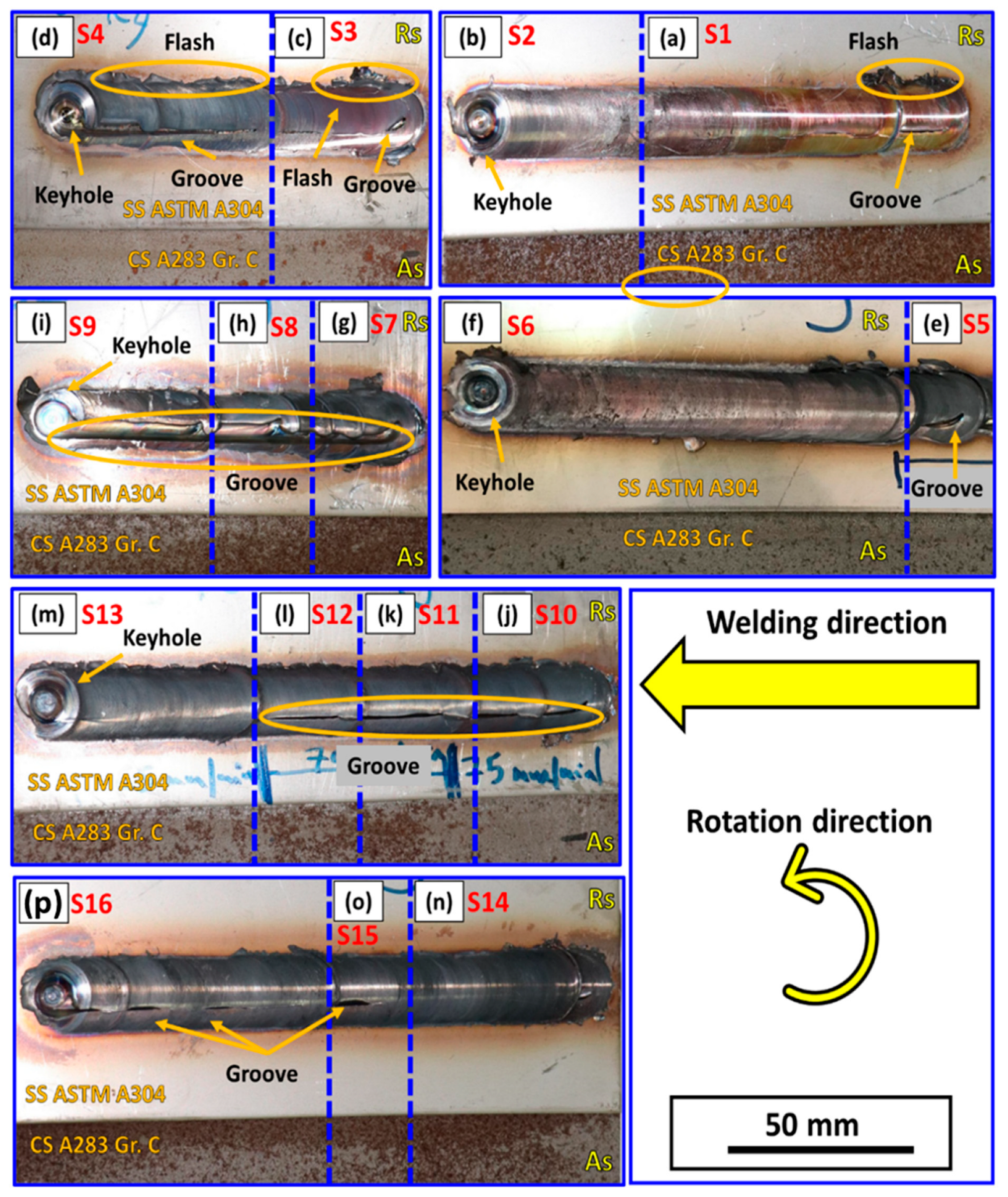
3.2. Visual Inspection of the Welded Joints

The visual examination serves as a standard approach for assessing the quality of welded joints. Figure 7 showcases photographs of dissimilar lap joints, fusing SS A304 and CS A283 Gr. C materials, with each joint designated a code from S1 to S16, as outlined in Table 3. Notably, defect-free lap joints were achieved for samples S2 (as seen in Figure 7b), S6 (Figure 7f), S13 (Figure 7m), and S14 (Figure 7n). Conversely, surface groove defects were identified on the top layer of dissimilar lap joints for samples S1 (Figure 7a), S3 through S5 (Figure 7c–e), S7 through S12 (Figure 7g–l), and S15 and S16 (Figure 7o,p). Previous studies, such as [21,22], suggest that such defects often occur when key process parameters—such as rotation speed, travel speed, and axial load—fail to generate adequate heat, compromising material flow in the SZ and resulting in an imperfect FSW joint. Fashami et al. [13] attribute surface groove defects in the friction stir processing (FSP) of AZ91 to inadequate tool shoulder pressure and improper travel and rotation speeds. Meanwhile, Zandsalimi et al. [23] attribute these defects in dissimilar joints of AA6061 Al-alloy and 430 stainless steel to excessive heat input, causing issues with material stirring in the SZ. Table 4 compiles the results of visual inspections conducted on the SS A304 and CS A283 Gr. C dissimilar lap joints fabricated under varying FSW conditions. According to this table, only samples S2, S6, S13, and S14 passed the visual quality check and were, therefore, subjected to further evaluations, including microstructure analysis, tensile testing, and hardness measurements.

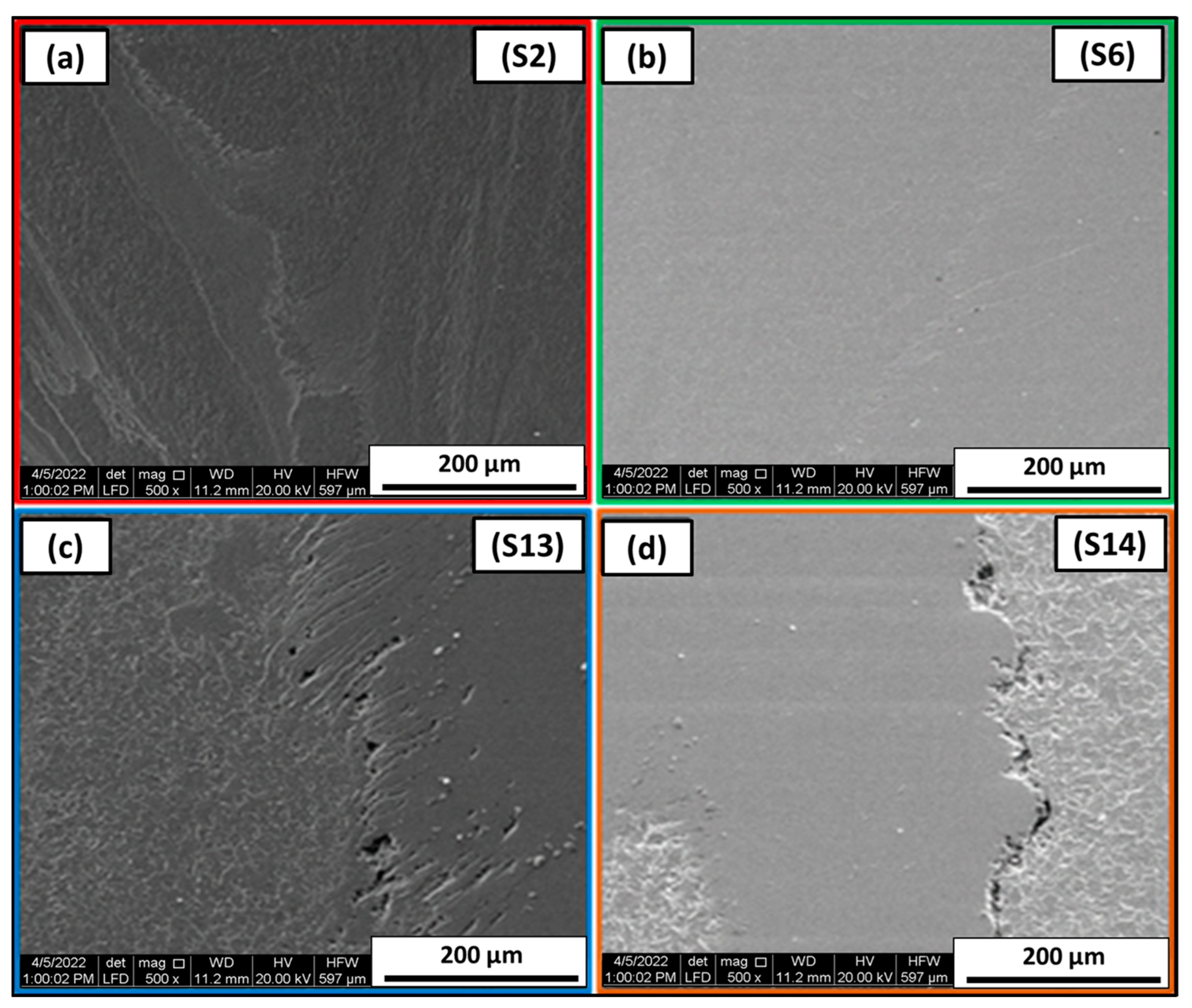
3.3. Macro and Microscopic Analysis of the Welded Joints

All the joints that passed the visual inspection (S2, S6, S13, and S14), as outlined in Table 4, have been subjected to further scrutiny through macro- and microstructure analyses. The optical macrographs of their transverse cross-sections are displayed in Figure 8, along with zoomed-in views of the nugget zone (NG) for each joint. Specifically, Figure 8a corresponds to joint S2, Figure 8b to S6, Figure 8c to S13, and Figure 8d to S14. Upon examination, it is evident that these joints have been successfully and flawlessly formed. A discernible band structure and mixing between the dissimilar materials—carbon steel and stainless steel—are apparent in all the analyzed joints. Similar results were reported on dissimilar FSW of Ti and steel alloys [24]. Interestingly, due to the stirring action during the welding process, the lower sheet, which is carbon steel, has moved upwards to intermingle with the upper sheet of stainless steel. This interaction is likely to contribute to increased joint strength and overall quality [25].
Figure 9 presents the optical microstructures of the successfully formed joints, specifically S2, S6, S13, and S14, at locations denoted by rectangles on their respective optical macrographs. One can observe the merging of the two different materials: carbon steel’s ferrite appears dark, while the austenite from stainless steel manifests as bright regions. The boundary between these dissimilar materials is visibly irregular, showcasing clear mixing at the microscopic level. This lack of uniformity is primarily due to the FSW tool’s stirring action and the lower material’s vertical flow during the welding process. Figure 9a,b spotlight the blending of carbon steel with stainless steel.
Additionally, grain refinement in carbon steel is noticeable, likely resulting from recrystallization during the high-temperature, high-strain conditions of FSW [18,25]. Grain refinement is expected in both types of steel due to the FSW process. Figure 8d and Figure 9c reveal an uneven boundary at the weld joint between carbon steel and stainless steel, along with further instances of grain refinement in ferrite. Figure 9e,f display the intricate mixing at the joint S13 interface, where miniature tendrils of stainless steel appear to intrude into the carbon steel matrix. Notably, the presence of micro-voids is indicated by arrows, likely resulting from the complex material flows during welding.
Similarly, Figure 9g,h illustrate the S14 joint interface, where an additional micro-void is discernible, marked by a black arrow. This is also presumed to result from intricate material flows during FSW. The interface between stainless steel and carbon steel appears irregular but with markedly fine grains evident on the carbon steel side. Figure 10 offers a more zoomed-in view of the interfaces between carbon steel and stainless steel, revealing a mix of regular and irregular features. Also, a fine-grain structure can be observed in the carbon steel welded plate which can be attributed to the dynamic recrystallization taking place upon FSW [18]. Further SEM investigations into these interfaces are depicted in Figure 11. It’s worth noting that the interfaces for joints S2 and S6 are remarkably free from any micro-defects, as shown in Figure 11a,b. Conversely, the interfaces for joints S13 and S14 exhibit some micro-voids, as indicated in Figure 11c,d.
A combination of EDS mapping, line scans, and spot analyses was utilized to examine the chemical composition changes across the interfaces of various joints. Figure 12 displays optical macrographs for each joint along with the specific locations where EDS mapping was conducted: S2 is illustrated in Figure 12a and further explored in Figure 13a; S6 appears in Figure 12b and is elaborated in Figure 13b; S13 is depicted in Figure 12c and detailed in Figure 14a; and S14 is shown in Figure 12d and further clarified in Figure 14b. Elemental line scans and spot analyses were executed to reveal element concentration and distribution and characterize the nature of the welded interfaces. Figure 15a–d provide line scan analyses across the stir zone interfaces, while Figure 16a,b show spot analyses for dissimilar lap joints of S2 and S6, respectively. The weld areas were prepared for further analysis by cutting and gentle polishing following the tensile shear tests on the lap joints. This allowed for a detailed study of the chemical composition within the shear welds, specifically on the carbon steel side. The findings from this analysis are presented in Figure 16.

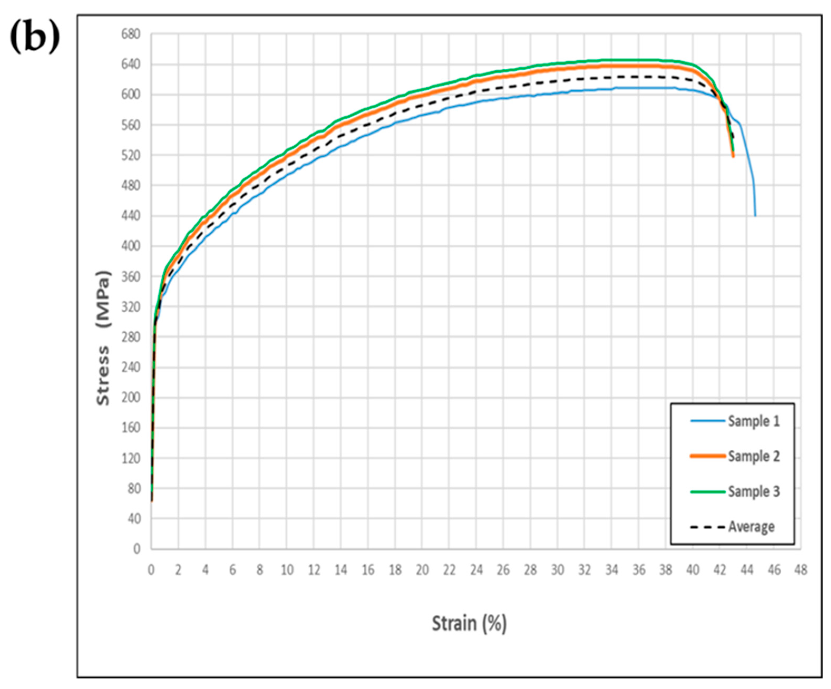
3.4. Evaluation of Mechanical Properties

The hardness characteristics of friction stir-welded (FSWed) dissimilar lap joints—specifically those visually accepted, such as “S2” between SS A304 and CS A283 Gr. C—are outlined in Figure 17. These particular joints were fabricated at a travel speed of 50 mm/min, a rotational speed of 300 rpm, and an axial load of 2.9 KN. Notably, the initial hardness values for SS A304 and CS A283 Gr. C were 213 HV and 202 HV, respectively. The hardness profile of the welded area reveals that the maximum hardness occurs in the SZ. Moreover, the thermo-mechanically affected zone (TMAZ) and the HAZ display higher hardness values than the original materials. Additionally, as depicted in Figure 17, the hardness levels in regions like the SZ, TMAZ, and HAZ are consistently lower for CS A283 Gr. C than for SS A304.
Figure 18 and Figure 19 illustrate the average Vickers hardness in the SZ for the dissimilar lap joints of SS A304 and CS A283 Gr. C, as previously described in Figure 4. The SZ hardness surpasses that of the Base Material (BM) in all the FSW joints across various regions of both SS A304 and CS A283 Gr. C. For SS A304, the top layer, Figure 18 reveals that the SZ’s maximum hardness is 259.7 HV. This value gradually diminishes to 245.8 HV in the TMAZ and further to 228.4 HV in the HAZ for the S6 FSW joint, which was created at a speed of 200 rpm, a travel speed of 25 mm/min, and an axial load of 2.8 KN; similarly, for the bottom layer of CS A283 Gr. C, Figure 19 shows that the SZ reaches peak hardness at 244.6 HV, which gradually tapers to 237.8 HV in the TMAZ and 225.3 HV in the HAZ. The variations in hardness can be attributed to the microstructural changes that occur during the FSW process. Severe plastic deformation and elevated temperatures in the SZ lead to substantial grain refinement due to dynamic recrystallization, which explains the highest hardness in this region. Conversely, the TMAZ experiences less plastic deformation and lower temperatures, resulting in less grain refinement and correspondingly lower hardness values. The HAZ, which shows no signs of deformation, undergoes only a heat cycle, leading to the lowest hardness values closer to those of the original base material.
The tensile shear load tests were conducted on the FSW dissimilar lap joints that passed visual inspection, as detailed in Table 4. The results indicate a range of tensile shear loads between 20 to 27 KN for the tested joints. The maximum tensile shear load was recorded for the S14 joint, which was welded at a travel speed of 25 mm/min, a rotational speed of 300 rpm, and an axial load of 2.6 KN. On the other hand, the lowest tensile shear load was observed for the S2 joint, which was fabricated at a much higher travel speed of 300 mm/min and a lower rotational speed of 50 rpm, with an axial load of 2.9 KN. Figure 20 presents these findings, while Figure 21 displays images of the fractured components following the tensile shear testing of the FSW joints.

4. Conclusions

This study explores the feasibility of using FSW to join A304 austenitic stainless steel with A283 Gr. C low-carbon steel in a lap joint configuration, aiming to clad the carbon steel with corrosion-resistant stainless steel. Implementing the FSW process to cladding A283 Gr. C with 304 austenitic stainless is crucial for various industrial applications due to its ability to combine the cost-effectiveness and formability of low-carbon steel with the corrosion resistance and durability of stainless steel. This process enhances the material’s resistance to rust, erosion, and chemical reactions, making it ideal for environments where exposure to harsh conditions, such as moisture, chemicals, or extreme temperatures, is a concern. The related applications include manufacturing storage tanks and pipelines. A broad range of FSW parameters were examined in this study to determine the optimum working parameters, including tool rotational speeds ranging from 200 to 400 rpm, tool travel speeds from 25 mm/min to 65 mm/min, and vertical forces between 20 KN and 3.2 KN. Based on the obtained results, the following conclusions can be outlined:
  • Combining high rotational speeds (400 rpm) and elevated vertical forces (32 KN) led to unacceptable joints characterized by poor surface finish and evident surface flaws. Conversely, more moderate rotational speeds of 200 and 300 rpm, combined with varying travel speeds and vertical forces, produced several high-quality joints.
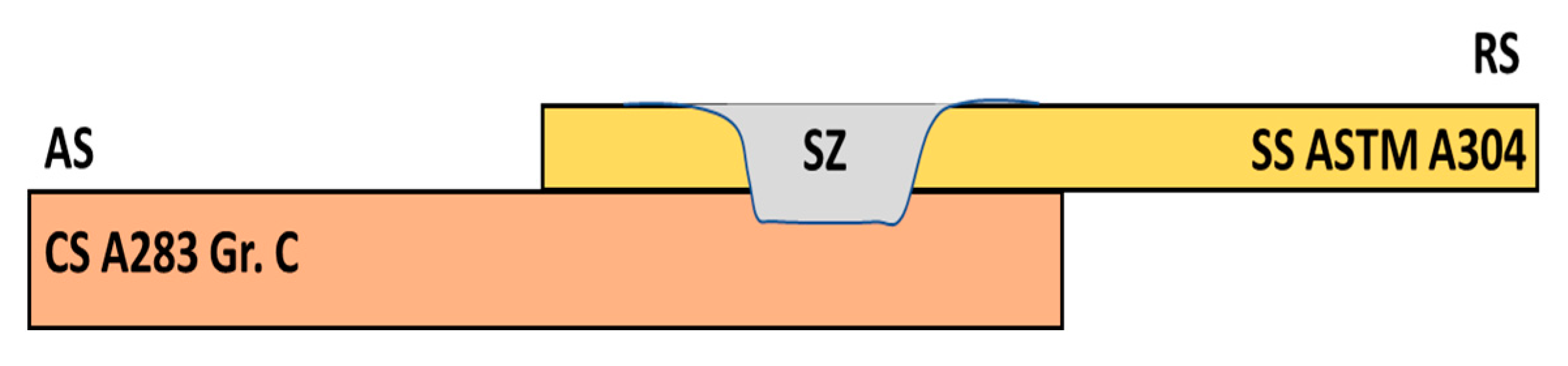
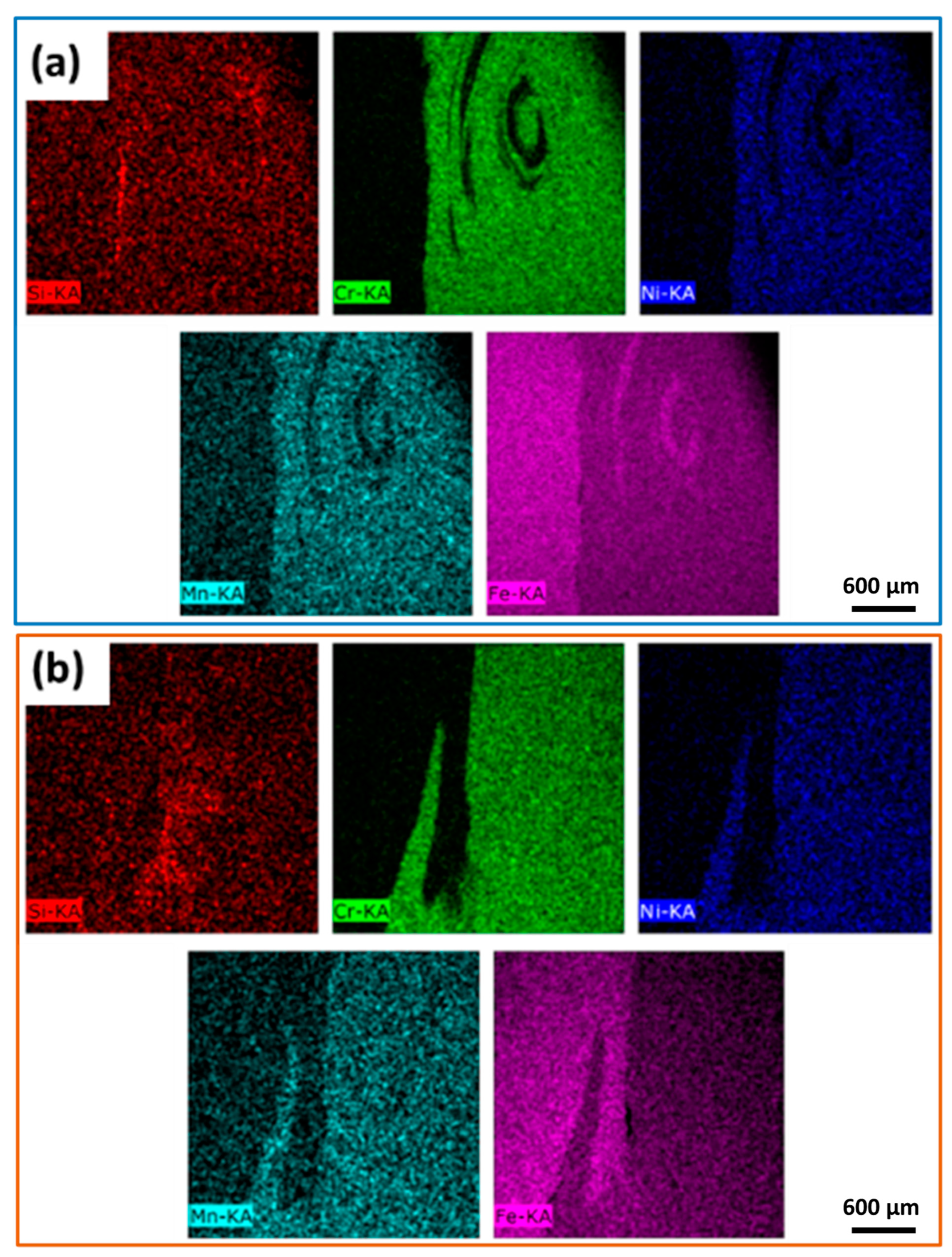
  • The transverse macrographs revealed a degree of intermingling between the two disparate materials, marked by an irregular interface.
  • The nugget zone showed a notable increase in hardness levels, peaking at 260 Hv in the stainless steel and 245 Hv in the carbon steel. This elevation in hardness can be primarily ascribed to grain refinement in the welded region, facilitated by dynamic recrystallization and thermomechanical transformations.
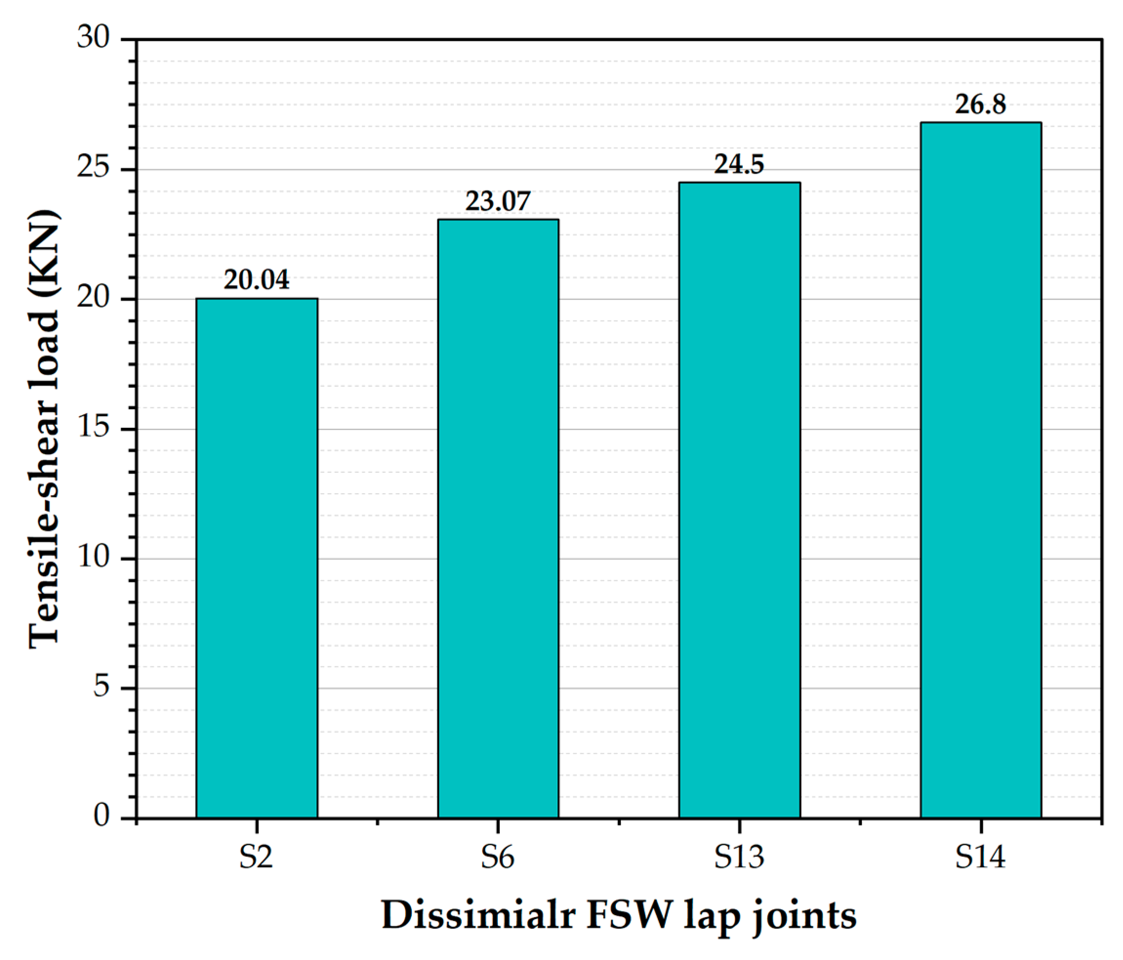
  • Tensile shear loads for these friction-stir-welded joints varied between 20 to 27 KN. The highest tensile shear load of 27 KN was observed in a welded joint at a tool rotation speed of 300 rpm and a travel speed of 25 mm/min.

Author Contributions

Conceptualization, M.S.I.A., M.M.Z.A., H.M.A.E.-A. and M.I.A.H.; validation, A.F.I., M.M.E.-S.S., A.A., B.A., A.A.E.-A. and W.M.F.; formal analysis, M.I.A.H.; investigation, M.S.I.A., M.M.Z.A., H.M.A.E.-A. and M.I.A.H.; resources, M.S.I.A., M.M.Z.A., H.M.A.E.-A., K.T. and M.I.A.H.; data curation, A.F.I., M.M.E.-S.S., A.A., B.A., A.A.E.-A. and W.M.F. writing—original draft preparation, M.S.I.A., M.M.Z.A., H.M.A.E.-A., K.T. and M.I.A.H.; writing—review and editing, M.S.I.A., M.M.Z.A., H.M.A.E.-A. and M.I.A.H.; visualization, M.S.I.A., M.M.Z.A., H.M.A.E.-A. and M.I.A.H.; supervision, M.S.I.A., M.M.Z.A., H.M.A.E.-A., W.M.F. and M.I.A.H.; project administration, A.F.I., M.M.E.-S.S., A.A., B.A., A.A.E.-A. and W.M.F.; funding acquisition, A.F.I., M.M.E.-S.S., A.A., B.A., A.A.E.-A., K.T. and W.M.F. All authors have read and agreed to the published version of the manuscript.

Funding

This study was supported by funding from Prince Sattam bin Abdulaziz University, project number (PSAU/2023/R/1444).

Data Availability Statement

Data will be made available upon request through the corresponding author.

Acknowledgments

This study was supported by funding from Prince Sattam bin Abdulaziz University, project number (PSAU/2023/R/1444).

Conflicts of Interest

The authors declare no conflict of interest.

References

  1. Wan, L.; Huang, Y. Friction Stir Welding of Dissimilar Aluminum Alloys and Steels: A Review. Int. J. Adv. Manuf. Technol. 2018, 99, 1781–1811. [Google Scholar] [CrossRef]
  2. Mishra, R.; Mahoney, M.W.; Sato, Y.; Hovanski, Y.; Verma, R. Friction Stir Welding and Processing VII. Frict. Stir Weld. Process VII 2016, 1–362. [Google Scholar] [CrossRef]
  3. Ahmed, M.M.Z.; Seleman, M.M.E.; Fydrych, D.; Cam, G. Friction Stir Welding of Aluminum in the Aerospace Industry: The Current Progress and State-of-the-Art Review. Materials 2023, 16, 2971. [Google Scholar] [CrossRef]
  4. Azevedo, J.; Infante, V.; Quintino, L.; dos Santos, J. Fatigue Behaviour of Friction Stir Welded Steel Joints. Adv. Mater. Res. 2014, 891–892, 1488–1493. [Google Scholar] [CrossRef]
  5. Abolusoro, O.P.; Akinlabi, E.T. Review and Analysis of Mechanical Properties of Friction Stir Welds of High Strength Aluminium Alloys. J. Phys. Conf. Ser. 2019, 1378, 042045. [Google Scholar] [CrossRef]
  6. Jafarzadegan, M.; Abdollah-zadeh, A.; Feng, A.H.; Saeid, T.; Shen, J.; Assadi, H. Microstructure and Mechanical Properties of a Dissimilar Friction Stir Weld between Austenitic Stainless Steel and Low Carbon Steel. J. Mater. Sci. Technol. 2013, 29, 367–372. [Google Scholar] [CrossRef]
  7. Jafarzadegan, M.; Feng, A.H.; Abdollah-Zadeh, A.; Saeid, T.; Shen, J.; Assadi, H. Microstructural Characterization in Dissimilar Friction Stir Welding between 304 Stainless Steel and St37 Steel. Mater. Charact. 2012, 74, 28–41. [Google Scholar] [CrossRef]
  8. Jacquin, D.; Guillemot, G. A Review of Microstructural Changes Occurring during FSW in Aluminium Alloys and Their Modelling. J. Mater. Process Technol. 2021, 288, 116706. [Google Scholar] [CrossRef]
  9. Mohan, D.G.; Wu, C.S. A Review on Friction Stir Welding of Steels. Chin. J. Mech. Eng. 2021, 34, 137. [Google Scholar] [CrossRef]
  10. Khedr, M.; Ibrahim, I.R.; Jaskari, M.; Ali, M.; Abdel-Aleem, H.A.; Mahmoud, T.S.; Hamada, A. Microstructural Evolution and Mechanical Performance of Two Joints of Medium-Mn Stainless Steel with Low- and High-Alloyed Steels. Materials 2023, 16, 1624. [Google Scholar] [CrossRef]
  11. Ahmed, M.M.Z.; Touileb, K.; El-Sayed Seleman, M.M.; Albaijan, I.; Habba, M.I.A. Bobbin Tool Friction Stir Welding of Aluminum: Parameters Optimization Using Taguchi Experimental Design. Materials 2022, 15, 2771. [Google Scholar] [CrossRef] [PubMed]
  12. Ahmed, M.M.Z.; El-Sayed Seleman, M.M.; Touileb, K.; Albaijan, I.; Habba, M.I.A. Microstructure, Crystallographic Texture, and Mechanical Properties of Friction Stir Welded Mild Steel for Shipbuilding Applications. Materials 2022, 15, 2905. [Google Scholar] [CrossRef] [PubMed]
  13. Ahmed, M.M.Z.; Hajlaoui, K.; Seleman, M.M.E.S.; Elkady, M.F.; Ataya, S.; Latief, F.H.; Habba, M.I.A. Microstructure and Mechanical Properties of Friction Stir Welded 2205 Duplex Stainless Steel Butt Joints. Materials 2021, 14, 6640. [Google Scholar] [CrossRef] [PubMed]
  14. Liu, F.C.; Hovanski, Y.; Miles, M.P.; Sorensen, C.D.; Nelson, T.W. A Review of Friction Stir Welding of Steels: Tool, Material Flow, Microstructure, and Properties. J. Mater. Sci. Technol. 2018, 34, 39–57. [Google Scholar] [CrossRef]
  15. Li, H.B.; Jiang, Z.H.; Feng, H.; Zhang, S.C.; Li, L.; Han, P.D.; Misra, R.D.K.; Li, J.Z. Microstructure, Mechanical and Corrosion Properties of Friction Stir Welded High Nitrogen Nickel-Free Austenitic Stainless Steel. Mater. Des. 2015, 84, 291–299. [Google Scholar] [CrossRef]
  16. Saeid, T.; Abdollah-zadeh, A.; Assadi, H.; Malek Ghaini, F. Effect of Friction Stir Welding Speed on the Microstructure and Mechanical Properties of a Duplex Stainless Steel. Mater. Sci. Eng. A 2008, 496, 262–268. [Google Scholar] [CrossRef]
  17. Sekban, D.M.; Aktarer, S.M.; Purcek, G. Friction Stir Welding of Low-Carbon Shipbuilding Steel Plates: Microstructure, Mechanical Properties, and Corrosion Behavior. Metall. Mater. Trans. A Phys. Metall. Mater. Sci. 2019, 50, 4127–4140. [Google Scholar] [CrossRef]
  18. Argade, G.R.; Shukla, S.; Liu, K.; Mishra, R.S. Friction Stir Lap Welding of Stainless Steel and Plain Carbon Steel to Enhance Corrosion Properties. J. Mater. Process Technol. 2018, 259, 259–269. [Google Scholar] [CrossRef]
  19. Wang, H.; Wang, K.; Wang, W.; Huang, L.; Peng, P.; Yu, H. Microstructure and Mechanical Properties of Dissimilar Friction Stir Welded Type 304 Austenitic Stainless Steel to Q235 Low Carbon Steel. Mater. Charact. 2019, 155, 109803. [Google Scholar] [CrossRef]
  20. Wang, H.; Zhang, C.; Zhou, Z.; Zhang, Y.; Wang, K.; Wang, W.; Han, P.; Lu, Y.; Li, X.; Liu, Y.; et al. Effect of the Microstructure on the Corrosion Behavior of Dissimilar Friction Stir-Welded 304 Austenitic Stainless Steel and Q235 Low-Carbon Steel Joints. Mater. Res. Express 2022, 9, 076508. [Google Scholar] [CrossRef]
  21. Chung, Y.D.; Fujii, H.; Ueji, R.; Tsuji, N. Friction Stir Welding of High Carbon Steel with Excellent Toughness and Ductility. Scr. Mater. 2010, 63, 223–226. [Google Scholar] [CrossRef]
  22. Ahmed, M.M.Z.; Abdelazem, K.A.; El-Sayed Seleman, M.M.; Alzahrani, B.; Touileb, K.; Jouini, N.; El-Batanony, I.G.; Abd El-Aziz, H.M. Friction Stir Welding of 2205 Duplex Stainless Steel: Feasibility of Butt Joint Groove Filling in Comparison to Gas Tungsten Arc Welding. Materials 2021, 14, 4597. [Google Scholar] [CrossRef] [PubMed]
  23. Zandsalimi, S.; Heidarzadeh, A.; Saeid, T. Dissimilar Friction-Stir Welding of 430 Stainless Steel and 6061 Aluminum Alloy: Microstructure and Mechanical Properties of the Joints. Proc. Inst. Mech. Eng. Part L J. Mater. Des. Appl. 2019, 233, 1791–1801. [Google Scholar] [CrossRef]
  24. Campo, K.N.; Campanelli, L.C.; Bergmann, L.; dos Santos, J.F.; Bolfarini, C. Microstructure and Interface Characterization of Dissimilar Friction Stir Welded Lap Joints between Ti–6Al–4V and AISI 304. Mater. Des. 2014, 56, 139–145. [Google Scholar] [CrossRef]
  25. Ghosh, M.; Kumar, K.; Mishra, R.S. Analysis of Microstructural Evolution during Friction Stir Welding of Ultrahigh-Strength Steel. Scr. Mater. 2010, 63, 851–854. [Google Scholar] [CrossRef]
Figure 1. (a) 3D exploded and assembly drawing FSW tool parts (all dimensions are in mm), (b) dimensions of FSW WC tool (all dimensions are in mm), (c) photo of WC tool geometry, and (d) dissimilar lap joints before FSW process.
Crystals 13 01559 g001
Figure 2. Schematic view of the transverse cross-section of the dissimilar lap joint.
Crystals 13 01559 g002
Figure 3. A schematic description of the tensile shear test sample (all dimensions are in mm).
Crystals 13 01559 g003
Figure 4. Schematic illustration of the hardness profile measurement across the dissimilar welded lap joint transverse cross.
Crystals 13 01559 g004
Figure 5. Optical microstructure and their associated grain size analysis of the (a) CS A283 Gr. C initial plate and (b) SS A304 initial plate.
Crystals 13 01559 g005
Figure 6. The engineering stress–strain curve of (a) A283 Gr. C initial plate and (b) SS A304 initial plate.
Crystals 13 01559 g006aCrystals 13 01559 g006b
Figure 7. Top surface view of the dissimilar lap joints of the SS A304 and CS A283 Gr. C welded via FSW process. (ap) Visual inspection of sample code S1–S16 respectively.
Crystals 13 01559 g007
Figure 8. Transverse optical macrographs and their corresponding magnified NG zone of the dissimilar FSWed lap joints between SS A304 and CS A283 Gr. C welded using different conditions: (a) S2 welded using 300 rpm, 50 mm/min and 2.9 KN, (b) S6 welded using 200 rpm, 25 mm/min and 2.8 KN, (c) S13 welded using 300 rpm, 65 mm/min and 2.400 KN, (d) S14 welded using 300 rpm, 25 mm/min and 2.6 KN.
Crystals 13 01559 g008
Figure 9. Optical microstructure at the interface between the lap dissimilar joints between stainless steel SS A304 (top) and carbon steel CS A283 Gr. C (bottom) produced using FSW. (a,b) sample S2, (c,d) sample S6, (e,f) sample S13, and (g,h) sample S14.
Crystals 13 01559 g009
Figure 10. Optical microstructure for the interface of the dissimilar lap joints (a) S6 and (b) S14.
Crystals 13 01559 g010
Figure 11. SEM image of the interface area of the dissimilar lap joints. (a) Sample S2, (b) Sample S6, (c) Sample S13, and (d) Sample S14.
Crystals 13 01559 g011
Figure 12. SEM/EDS mapping for the distribution of elements of the dissimilar lap joints: (a) S2, (b) S6, (c) S13, and (d) S14.
Crystals 13 01559 g012
Figure 13. SEM/EDS single maps for elements of (a) S2 and (b) S6 lap joints.
Crystals 13 01559 g013
Figure 14. SEM/EDS single maps for elements of (a) S13 and (b) S14 lap joints.
Crystals 13 01559 g014
Figure 15. EDS Line scan analysis along yellow arrow of stir zone crosses the interface for dissimilar lap joints. (a) S2, (b) S6, (c) S13, and (d) S14.
Crystals 13 01559 g015
Figure 16. SEM/EDS spot lines for elements of (a) S2 and (b) S6 lap joints.
Crystals 13 01559 g016
Figure 17. Hardness Vickers profile of the dissimilar lap joints of the SS A304 and CS A283 Gr. C welded at a travel speed of 50 mm/min, 300 rpm rotation speed, and axial load of 2.9 KN.
Crystals 13 01559 g017
Figure 18. The average Vickers hardness of the SZ, TMAZ, and HAZ for the SS A304.
Crystals 13 01559 g018
Figure 19. The average Vickers hardness of the SZ, TMAZ, and HAZ for the CS A283 Gr. C.
Crystals 13 01559 g019
Figure 20. Tensile shear load results of the dissimilar lap joints of the SS A304 and CS A283 Gr. C welded using the FSW process. Note, sample width is 20 mm.
Crystals 13 01559 g020
Figure 21. Tensile shear load results of the dissimilar lap joints of the SS A304 and CS A283 Gr. C welded using the FSW process. (a) S2, (b) S6, (c) S13, and (d) S14.
Crystals 13 01559 g021
Table 1. Summarization of previous works concentrated on the FSW of stainless steel and low-carbon steel.
No.MaterialsWelding TechniqueMajor ObservationsRef.
1AISI 1018 carbon steel plate (6.35 mm)/AISI 316L stainless (2.7 mm)—Lap jointFSW/cubic boron nitride toolDeveloped microstructure with refined and equiaxed austenite grains with a small fraction of ferrite and martensite—100% joint efficiency.[18]
2304 austenitic Stainless Steel/st37 Low Carbon Steel—Butt jointFSW/tungsten carbide toolRecrystallization of austenite in st37 carbon steel—Hardness increased in the WZ compared to both initial materials—Tensile strength and ductility higher than the st37 initial steel.[6]
3304 austenitic stainless steel (3 mm)/Q235 low carbon steel (3 mm)—Butt jointFSW/tungsten carbide toolGrain refining and hardness increased in the stir zone—24% improvement in the tensile strength of the stir zone[19]
4304 austenitic stainless steel (3 mm)/Q235 low carbon steel (3 mm)—Butt jointFSW/tungsten carbide toolThe mixed microstructure in the stir zone was mainly formed of austenite, proeutectoid ferrite, pearlite, and bainite. And the corrosion mechanisms corresponded to galvanic corrosion.[20]
Table 2. Chemical composition (wt.%) of CS A283 Gr. C and SS A304.
Fe %C %Si %Mn %P %S %Cr %Ni %
A283 Gr. C98.9410.030.220.770.0190.02----
A30471.3090.0290.391.450.0220.0118.028.77
Table 3. Dissimilar FSW process parameters.
Sample No.CodeRotation Speed
(rpm)
Travel Speed
(mm/min)
Load
(KN)
1S1300502.5
S2300502.9
2S3400502.0
S4400502.2
3S5200502.8
S6200252.8
4S7400253.2
S8400203.2
S9300253.2
5S10300752.3
S11300752.4
S12300702.4
S13300652.4
6S14300252.6
S15300252.2
S16300252.4
Table 4. Visual inspection report of the SS A304 and CS A283 Gr. C dissimilar lap joints.
Sample No.CodeVisual AppearanceSurface DefectResults
FlashGroove
1S1Partially goodSmallDetectedRejected
S2GoodVery smallNoneAccepted
2S3Partially goodSmallDetectedRejected
S4Partially goodSmallDetectedRejected
3S5Partially goodVery smallDetectedRejected
S6Very goodVery smallNoneAccepted
4S7BadSmallDetectedRejected
S8BadSmallDetectedRejected
S9BadSmallDetectedRejected
5S10BadVery smallDetectedRejected
S11BadVery smallDetectedRejected
S12BadVery smallDetectedRejected
S13Very goodVery smallNoneAccepted
6S14Very goodVery smallNoneAccepted
S15Partially goodVery smallDetectedRejected
S16Partially goodVery smallDetectedRejected
Disclaimer/Publisher’s Note: The statements, opinions and data contained in all publications are solely those of the individual author(s) and contributor(s) and not of MDPI and/or the editor(s). MDPI and/or the editor(s) disclaim responsibility for any injury to people or property resulting from any ideas, methods, instructions or products referred to in the content.

