Article

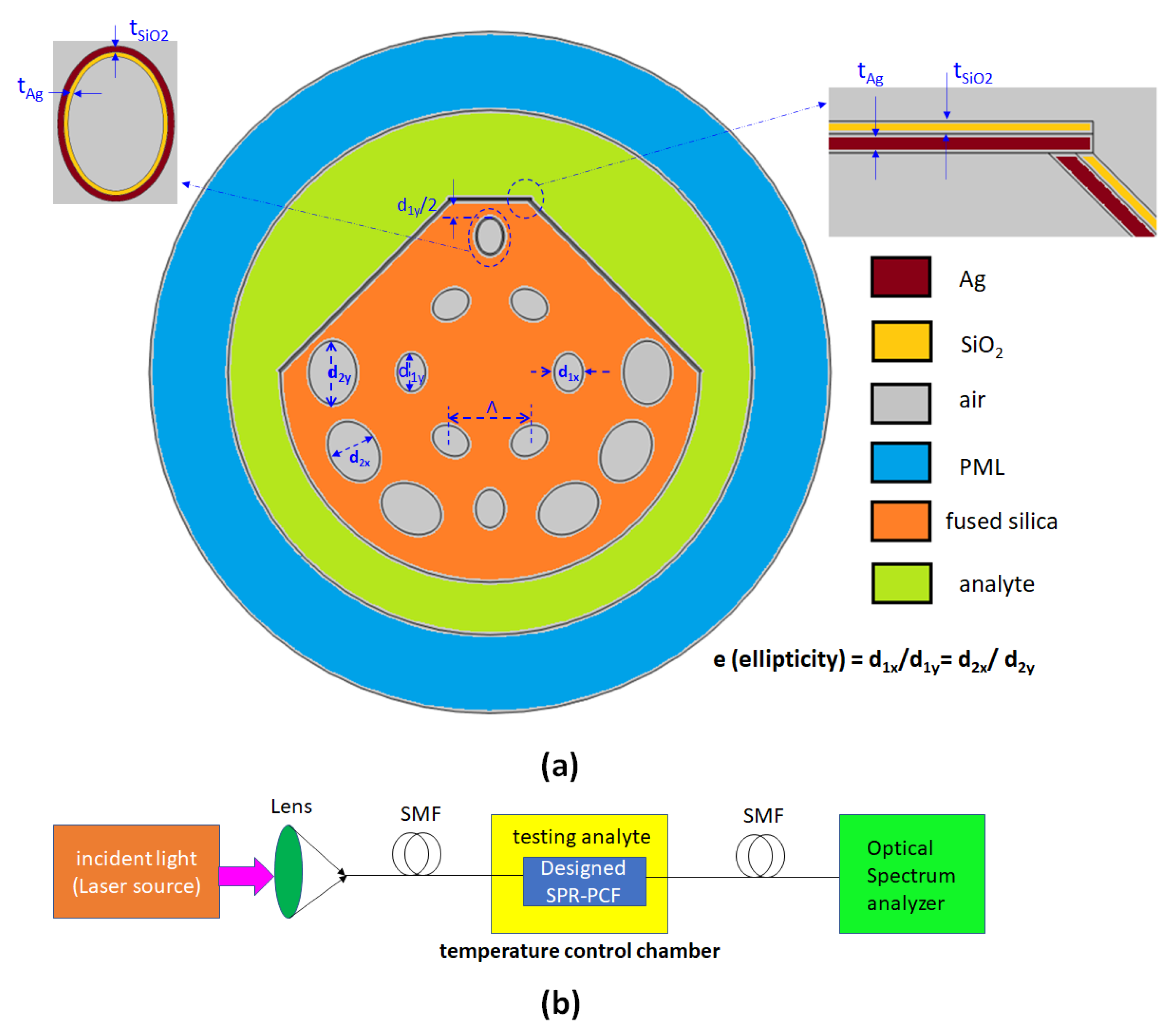
Improving Temperature-Sensing Performance of Photonic Crystal Fiber via External Metal-Coated Trapezoidal-Shaped Surface

by
Chung-Ting Chou Chao
1,
Sy-Hann Chen
2,
Hung Ji Huang
3,
Muhammad Raziq Rahimi Kooh
4,
Chee Ming Lim
4,
Roshan Thotagamuge
5,
Abdul Hanif Mahadi
4 and
Yuan-Fong Chou Chau
4,*
1
Department of Optoelectronics and Materials Technology, National Taiwan Ocean University, Keelung 20224, Taiwan
2
Department of Electrophysics, National Chiayi University, Chiayi 600, Taiwan
3
Department of Electra-Optical Engineering, National Formosa University, Yunlin County 632, Taiwan
4
Centre for Advanced Material and Energy Sciences, Universiti Brunei Darussalam, Tungku Link, Gadong BE1410, Brunei
5
Department of Nano Science Technology, Faculty of Technology, Wayamba University of Sri Lanka, Kuliyapitiya 60200, Sri Lanka
*
Author to whom correspondence should be addressed.
Crystals 2023, 13(5), 813; https://doi.org/10.3390/cryst13050813
Submission received: 25 April 2023 / Revised: 8 May 2023 / Accepted: 12 May 2023 / Published: 13 May 2023
(This article belongs to the Section Hybrid and Composite Crystalline Materials)

Abstract

:
This article describes a photonic crystal fiber (PCF) temperature sensor that utilizes a flat, metal-coated trapezoidal surface. The PCF is made up of two layers of elliptical air holes and a polished trapezoidal surface that allows temperature sensing. An external sensing approach is used to deposit a thin silver layer on the reflective surface, while a thin SiO2 film acts as an oxidation-resistant coating. The top elliptical air hole serves as the interface for energy transformation from the core-guided mode to the surface plasmon-polariton (SPP) mode. Simulations carried out using the finite element method indicate that the proposed SPR-PCF temperature sensor can achieve a maximum temperature sensitivity and resolution of up to 5200 pm/°C and 0.01923 °C, respectively, across a temperature range of 10 to 60 °C. This research has significant potential for sensor design and real-time temperature remote sensing applications.

1. Introduction

Surface plasmon resonance (SPR) and surface plasmon polariton (SPP) are related to the collective oscillation of electrons known as plasmons, which occur at the interface of a metal and a dielectric material [1,2]. The effects of SPR refer to the phenomenon of enhanced light absorption and scattering at the interface of a metal and a dielectric material due to the excitation of plasmons, which have gained significant attention due to their promising applications in nanophotonics [3,4]. SPPs are propagating plasmons that occur at the interface of a metal and a dielectric material and can confine electromagnetic (EM) fields to the nanoscale [5,6,7]. If the wavelength of the incident EM wave matches the wavelength of the plasmon oscillation, significant resonance occurs, producing an SPR mode. The SPR effect is sensitive to changes in the refractive index (RI) of the surrounding medium. This property is advantageous for different SPR sensors and has broad applications and research impacts [8,9,10,11,12,13,14,15,16,17,18,19,20,21].
SPR is effectively used in plasmonic nanostructure sensors. Researchers have designed various SPR sensors using the unique property of SPR [22]; for example, waveguide or fiber-based RI sensors such as prism-coupling SPR sensors [23,24], metal–insulator–metal (MIM) waveguide-based sensors, a periodic array of rod-shaped plasmonic sensors [10,25], fiber Bragg gratings [26,27], microring resonators, and plasmonic PCF sensors [26]. SPR biosensors can detect biological samples near the metal surface using the resonance mechanism [28]. The SPR-PCF sensor utilizes the core-guided and SPP modes when in the phase-matching condition [29]. Most of the energy in the core region is coupled to the metallic surface, and the energy in the core region decreases rapidly [30]. This phenomenon is characterized by confinement loss (CL) in the PCF, and CL increases sharply as the resonance wavelength increases [31]. Compared to traditional PCFs, SPR-PCF sensors have higher sensitivity and narrower full width at half maximum (FWHM), making them more advantageous.
The SPR-PCF sensor is a crucial component in various studies and research related to analyte detection, biomedical applications, biosensing, food quality measurement, and environmental testing [32]. To enhance sensor performance, researchers have developed different types of SPR-PCF sensors. These include a uniform metal coating inside a selected air hole (known as the internal method) and an externally coated metal film on the polished surface of the SPR-PCF (known as the external process) [33]. However, the internal method has the disadvantage of having difficulty filling the test medium within the small size of the selected air hole. However, the external approach enables rapid deposition of the sensing analyte on the surface of the SPR-PCF [34].
For the internal method, Yuan et al. designed an SPR-PCF design for liquid RI detection that breaks the symmetry of the cladding region and includes a detection channel with gold-coated elliptical air holes [35]. They achieved high sensitivity through the metal coating inside the PCF cladding. Rift et al. developed a highly sensitive SPR-PCF with a large cavity to attract the SPP mode and infiltrated the sensing elements, with a wavelength sensitivity of 11,000 nm/RIU [36]. Zhan Q. et al. created an SPR-PCF temperature sensor using a Au nanowire to excite the SPP mode, achieving a maximum sensitivity of 4.98 nm/°C [8]. Li et al. investigated an H-shaped SPR-PCF coated with silver graphene layers for RI sensing and achieved a sensitivity of 2770 nm/RIU and a resolution of 3.61 × 10⁻⁵ RIU [37]. Mei et al. proposed a dual-core PCF with a temperature sensitivity of 6.32 nm/°C, but its fabrication process is complicated due to the use of many air holes (thirty-two airholes) [38].
For the external method, Rahman et al. investigated a microchannel SPR-PCF sensor with an externally coated Au layer (30 nm) on the polished surface and achieved a wavelength sensitivity of up to 25,000 nm/RIU [39]. Yang et al. designed a D-shaped SPR-PCF sensor that can function as both an RI and a temperature sensor, with the y-polarized channel sensing the RI sensitivity and the x-polarized channel serving as a temperature sensor [40]. Wang et al. also designed a D-shaped PCF and demonstrated a temperature sensitivity of 6.36 nm/°C [41].
On the basis of the exciting developments in the field, we propose a novel SPR-PCF temperature sensor that consists of two layers of elliptical air-hole rings of different sizes [42]. The upper elliptical air hole serves as the interface for transferring energy from the core region to the metallic surface. A coated Ag/SiO2 layer is located inside the top elliptical air hole and outside the flat surface of the SPR-PCF structure. The trapezoid structure facilitates the coupling effect between the core-guided and SPP modes. The SPR-PCF with elliptical air-hole rings is less discussed in previous articles and this design allows for straightforward temperature-analyte detection by filling it onto the outer surface of the SPR-PCF. We performed simulations using the finite element method (FEM)-based software COMSOL Multiphysics with perfectly matched layer (PML) boundary conditions to eliminate reflection light at the borders. We investigated the E-field intensity distribution, CL, and resolution to inspect the sensing performance. Furthermore, we examine the influence of the thickness of Ag, SiO2, ellipticity, and air hole sizes for further structural optimization. The novelty of this work lies in the elliptical air holes in the fiber cladding, which greatly influence the CL spectrum, offering an additional degree of freedom and flexibility to tune the optical response of the plasmonic system compared to a uniform circular-hole fiber sensor. The proposed SPR-PCF temperature sensor exhibits excellent temperature sensitivity and resolution with good linearity.

2. Materials and Methods

The FEM simulations were performed using a meshing grid with finer elements consisting of 17,278 domain elements and 1466 boundary elements. To minimize the reflection of light, we placed a PML boundary at the outermost layer of the SPR-PCF to absorb any reflected light.
In this study, we used a minimal number of elliptical air holes in the SPR-PCF design to achieve higher light confinement in the core region. The designed SPR-PCF temperature sensor is shown in Figure 1a. The inner circle is composed of six small holes arranged in a hexagonal pattern, the outermost ring consists of six large holes, and there are two unique vertical small holes that do not belong to either circle. The two-layer elliptical air holes with two different sizes and the same ellipticity were arranged in a specific pattern to form the inner structure of the PCF. This pattern effectively confines the core-guided mode in the fiber core region and facilitates interaction between the core-guided mode and the SPP mode. FEM simulations indicate that this pattern has minimal impact on sensing performance, and we can further optimize the performance by adjusting the structural parameters, as discussed in Section 3.
In Figure 1a, the colors represent the different materials used in the proposed SPR-PCF design. The smaller elliptical air holes are located on the inner wall, whereas the larger ones are on the outer wall. The outermost upper air hole and the polished trapezoidal-shaped surface are coated with Ag and SiO2 films. Ag was chosen as the SPR excitation source because of its sharper resonance peak compared to other metals. The SiO2 film acts as an oxidation-resistant coating.
The liquid to be detected is filled around the SPR-PCF, and changes in ambient temperature cause changes in the liquid’s RI as per Equation (2). In Figure 1a, the green region is filled with a temperature-sensitive liquid mixture of ethanol and chloroform, and the dispersion of the liquid is neglected [41]. Changes in temperature cause changes in the RI of the ethanol and chloroform mixtures, leading to variations in the SPR resonance condition. Temperature sensitivity can be calculated on the RI and the corresponding resonance wavelength (λres).
The structural parameters are the pitch along the x-axis (Λ), major and minor axes of the small and large elliptical air holes (d1y, d1x, d2y, d2x), the Ag thickness (tAg), the SiO2 thickness (tSiO2), the polish depth (that is, the gap between the upper air hole and the upper flat Ag/SiO2 layer) (d1y/2), temperature (T, °C), and the ratio of the minor and major axes of the elliptical air holes (that is, ellipticity, e = d1x/d1y = d2x/d2y), respectively. The angle between the x-axis and the trapezoidal-shaped surface is set at 60°. The entire matrix of the temperature SPR-PCF sensor uses silica as the cladding and core materials, and its material dispersion is considered in the Sellmeier equation [43].
n 2 λ , T = 1.31552 + 6.90754 × 10 6 T + 0.788404 + 23.5835 × 10 6 T λ 2 λ 2 0.0110199 + 0.584758 × 10 6 T + 0.91316 + 0.548368 × 10 6 T λ 2 λ 2 100
where λ is the incident light wavelength (the unit of µm) and T is the temperature (in °C, Celsius).
A mixture of ethanol and chloroform can express the thermosensitive liquid, which is RI [44,45].
n T = x % × n e t h a n o l T = 20 + d n e t h a n o l d T × T 20 + 100 x % × n c h l o r o f o r m T = 20 + d n c h l o r o f o r m d T × T 20
Here, x% and (100 − x)% represent the ratio of ethanol and chloroform, respectively. We calculate the permittivity of Ag using the Drude–Lorentz dispersion model [46].
ε m = ε ω p 2 ω 2 i ω γ
Here, ε (dielectric constant at infinite frequency) = 3.7, ωp (bulk plasma frequency) = 9.1 eV, and γ (electron collision frequency) = 0.018 eV, respectively. The temperature properties of the Ag film can be ignored because the temperature-sensitive liquid is more sensitive to temperature than Ag [47]. We set the refractive index of SiO2 at n = 1.45. The CL can be expressed as [48].
α 8.686 × 2 π λ × I m n e f f × 10 4 d B c m
Here, Im [neff] represents the imaginary part of the effective RI. Temperature sensitivity is obtained by
S A λ n m / ° C = Δ λ r e s / Δ T
where Δλres is the change in resonance wavelength and ΔT denotes the change in two successive temperatures.
The temperature resolution is [49].
R = Δ T × Δ λ min / λ res .
Here, Δλmin is the least wavelength resolution.
The proposed PCF sensors can be implemented in actual practice. Due to the advanced nanofabrication technology, elliptical air holes in SPR-PCF can be manufactured using the existing fabrication technologies, such as die-casting, capillary stacking, and stack-and-draw [50]. The fabrication of the proposed structure can be carried out based on experimental progress made in the field [50,51,52,53]. Figure 1b illustrates the experimental device used for this temperature sensor [54]. This device is easy to implement [55].

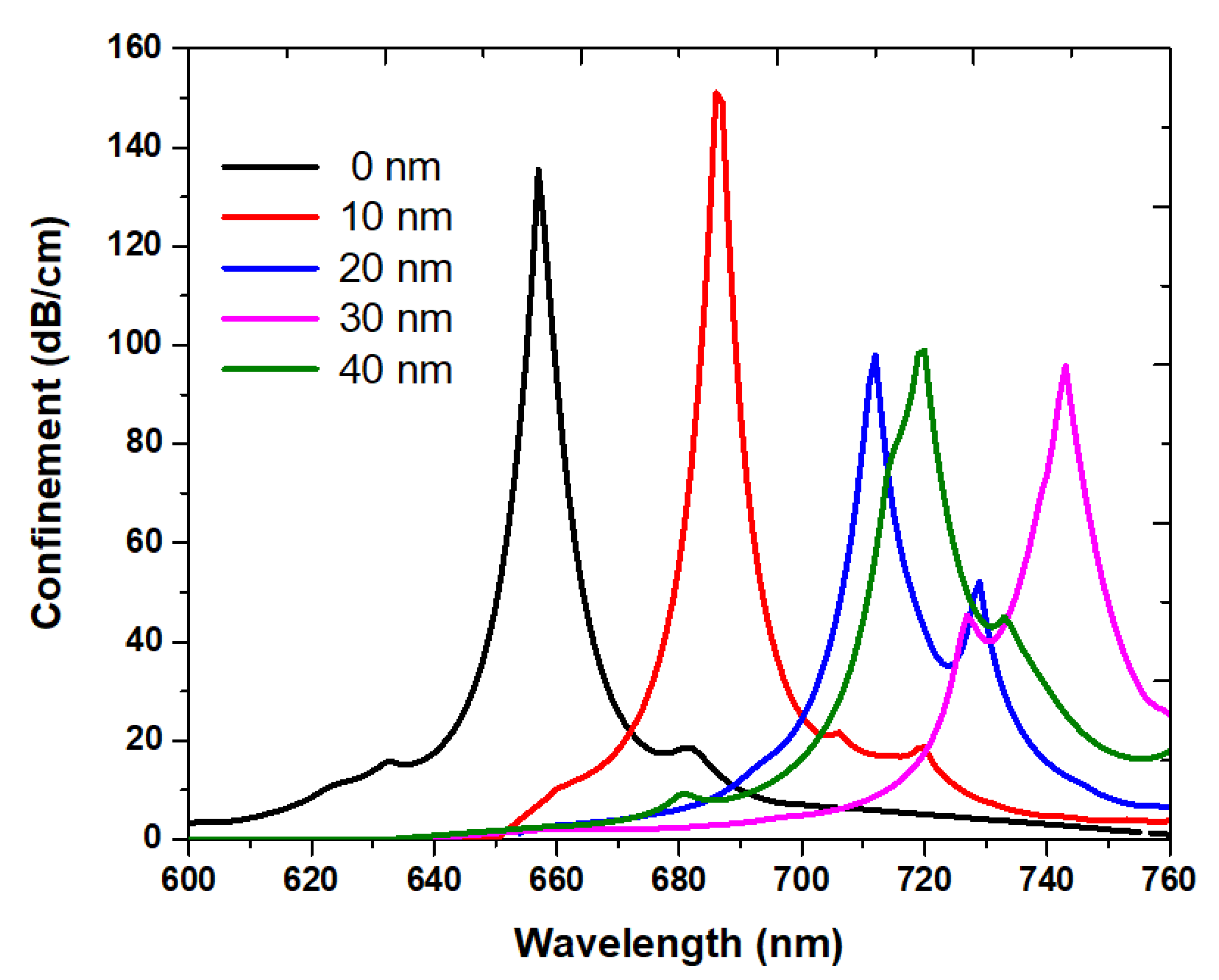
3. Results and Discussion

Based on the FEM simulations [56,57,58,59], the optimized values of the structural parameters have been determined and are presented in Table 1.
The sensing mechanism of the proposed SPR-PCF can be explained as follows. As incident light travels through the fiber core region, it generates an evanescent field that produces polarized light. This polarized light penetrates the core region and reaches the metal surface, causing the free-electron gas on the metal surface to discharge. The resonance condition occurs when the core-guided and SPP modes coincide at a specific wavelength, resulting in a peak in the reflectance spectrum [39]. From the perspective of SPP modes, there are propagating SPP modes on the metal surface and locally confined SPP modes at two sharp corners in the proposed SPR-PCF structure. The propagating SPP mode dominates the electric field distribution and contributes to the sensing performance as it provides more CL compared to the locally confined SPP mode.
Figure 2a–e depict the E-field intensity distribution of the fundamental x-polarized core-guided mode, y-polarized core mode 1, y-polarized core mode 2, y-polarized SPP mode 1, and y-polarized SPP mode 2, respectively. Structural parameters are adopted in Table 1. The green color indicates the surface arrows of the E fields. As shown in Figure 2a,b, there is a more significant SPP effect in the y-polarization compared to the x-polarization, resulting in a higher CL in the y-polarization direction than in the x-polarization direction. This phenomenon occurs because the top elliptical air hole has a more substantial interaction with the trapezoidal-shaped Ag film in the y direction. The upper elliptical air hole serves as the bridge and interface to connect the core-guided mode to the SPP mode. Therefore, in subsequent simulations, we investigate the CL versus wavelength in the y-polarization direction of core mode 1 due to the higher effective RI.
When the incident wavelength of the core-guided mode matches that of the SPP mode, an SPP wave is generated, which is sensitive to the RI of the surrounding layer. This can be explained by the phase-matching properties, where the real part of the effective RI of the fundamental core-guided mode matches that of the SPP mode. The coupling between the core-guided mode and the SPP mode results in a peak in the coupling strength when the resonant conditions are met [39,60,61]. The dispersion relationship between the core-guided mode and the SPP mode is shown in Figure 3. In this figure, the real part of the core-guided mode decreases with increasing wavelength. When the wavelengths are 712 nm and 729 nm, the RI of the core-guided mode intersects with that of the SPP mode (indicated by the cross points of the black and red lines in Figure 3). At these resonance wavelengths (i.e., λres = 712 nm and 729 nm), the energy generated from the core-guided mode couples to the SPP mode, resulting in the maximum coupling strength. In this scenario, the energy produced by the core-guided mode couples with the SPP mode, resulting in a maximum CL at the two resonance wavelengths. At wavelengths labeled SPP mode 1 and SPP mode 2, there are abrupt changes in the effective RI of both the core-guided mode and the SPP mode. The step-like variation in the red and black curves of the RI (unlike the CL of the smooth blue curve of the core-guided mode) is due to the RI change when the energy of the core-guided mode rapidly transforms to the SPP mode from the fiber core region to the metal surface. This result is similar to other research studies (see, e.g., [41,54,62,63,64]). This phenomenon can be explained by the fact that CL is proportional to Im(neff) [65].
Figure 4a shows the CL as a function of the wavelength of the core-guided mode at temperatures ranging from 10 °C to 60 °C, using the structural parameters listed in Table 1. Resonance wavelengths λres corresponding to each temperature are 791 nm, 758 nm, 712 nm, 655 nm, 625 nm, and 604 nm, respectively. It can be seen that the λres peaks blue shift with increasing temperature due to the variation of effective RI. The RI of the analyte is a mixture of ethanol and chloroform (calculated using Equation (2)), with values of 1.4011, 1.3957, 1.3908, 1.3857, 1.3805, and 1.3754 at 10 °C, 20 °C, 30 °C, 40 °C, 50 °C, and 60 °C, respectively. This decrease in the RI of the analyte results in an overall reduction in the effective RIs of the SPR-PCF sensor components with increasing temperature. Consequently, the transfer of core energy to the SPP wave is weakened due to the lower coupling efficiency between the core region and the metal surface at higher temperatures [66,67].
In Figure 4b, it can be observed that the λres decreases as temperature increases, as seen at points A-F. This decrease in λres peak is associated with a reduction in CL on the Ag surface. The λres peak decreases with increasing temperature from 10 °C to 60 °C. According to Equation (3), the CL peak is related to the permittivity of Ag and the real part of the RI of the temperature analyte, which is also temperature dependent [20].
To investigate the temperature sensitivity of the designed structure, we varied the temperature from 10 °C to 60 °C and calculated the corresponding Δλres and ΔT. Note that effective SPP modes are not available outside the temperature range of 10–60 °C. Therefore, the temperature range is limited to 10–60 °C for proper operation of the SPP modes. Using Equation (4), we obtain the temperature sensitivity S, which is represented by the slope of the curve in Figure 4b. As shown in Figure 4b, the dependence of λres on temperature is plotted. The slopes between adjacent points correspond to the temperature sensitivity and were found to be SAB = 5200 pm/°C, SBC = 4000 pm/°C, SCD = 3300 pm/°C, SDE = 2800 pm/°C, and SEF = 2300 pm/°C, respectively. The fitted relationship in Figure 4b can be expressed as
λ res   ( nm ) = 3.9749 × T + 829.93 ,   0   ° C     T     60   ° C
The slope (see Equation (7)) reveals a sensitivity of 3974.9 pm/°C with an R square value of 0.99484 at 10 °C ≤ T ≤ 60 °C. Moreover, the figure of merit (FOM) can be defined as FOM = S/FWHM, where FWHM is the full width at a half maximum of the resonance wavelength. The calculated FOMs are FOMAB = 1.73/°C, FOMBC = 0.4/°C, FOMCD = 0.33/°C, FOMDE = 0.47/°C and FOMEF = 0.46/°C, respectively.
The temperature resolution of the designed SPR-PCF sensor can be obtained by Equation (5), using the values of Δλres and sensitivity values (SAB) calculated earlier in Figure 4b. For SAB, the values of ΔT and Δλres are 10 °C and 52 nm, respectively. Assuming Δλmin = 0.1 nm, the maximum sensitivity and resolution can be calculated to be 5.200 pm/°C and 0.01923 °C, respectively.
The impact of structural parameters on the CL spectrum varies, and the SPP waves are sensitive to the thickness of the metal layer. Figure 5, Figure 6, Figure 7, Figure 8 and Figure 9 investigate the influence of the SPR modes according to the structural parameters and find the available range of structural parameters that function in the SPP modes. Specifically, the thickness of the Ag layer (tAg) is a significant factor that affects the CL value. Figure 5 shows the CL as a function of wavelength for different tAg values while keeping other structural parameters constant (as shown in Table 1). As shown in Figure 5, λres experiences a redshift and a decrease in the λres peak for values of tAg < 25 nm and tAg > 35 nm. This phenomenon can be explained by the increase in the effective metal RI with an increase in tAg, resulting in a redshift of λres. A thinner tAg (e.g., tAg = 20 nm) induces a weaker SPP wave on the metal surface. In contrast, a thicker tAg (e.g., tAg = 40 and 50 nm) impedes the penetration of the E-field, resulting in significant suppression of the CL trend of the CL [67]. Based on the curve in Figure 5, the range of tAg is limited to 25 nm tAg < 35 nm for the proposed SPR-PCF. These results suggest that the thickness of the Ag layer greatly influences λres and CL intensity, and the desired working wavelength can be adjusted by varying tAg.
Figure 6 shows the CL versus wavelength for various SiO2 thicknesses (tSiO2) of 0, 10, 20, 30, and 40 nm using the structure parameters in Table 1. When tSiO2 is 0 nm (the uncoated case) and 10 nm, the CL peak has a higher value than tSiO2 = 20 nm, 30 nm, and 40 nm, showing a narrower FWHM. In real conditions, the uncoated case has the drawback of easy oxidation on the Ag surface. A thicker tSiO2 increases the effective RI, leading to a redshift of λres and fewer CL, resulting in a weaker coupling to the metallic surface. The thickness of the SiO2 layer does not affect the performance of the confinement spectrum, as is evident in Figure 6. However, a thin tSiO2 has a negative impact on resistance to oxidation of the Ag layer. Therefore, the suitable tSiO2 range for the proposed SPR-PCF is selected as 20 nm tSiO2 ≤ 40 nm.
The proposed SPR-PCF has six smaller elliptical air holes located at the first layer, with two more at the top and bottom of the second layer. These holes significantly affect the coupling between the core-guided mode and the SPP mode. We investigated the size of the major axis of the smaller elliptical air holes (d1y), with other structural parameters remaining unchanged (as listed in Table 1). Figure 7 shows the CL versus wavelength for d1y = 0.30, 0.32, 0.34, 0.36, 0.38, and 0.40. The increase in CL indicates a stronger coupling effect, facilitating the energy transformation from the core-guided to the SPP mode. As seen in Figure 7, the strongest CL occurred when 0.30 µm ≤ d1y ≤ 0.36 µm and the weakest CL occurred when d1y ≥ 0.38 µm. Therefore, the size of the major axis of the smaller elliptical air holes (d1y) plays a critical role in CL because it can influence the fundamental core-guided mode that matches the SPP mode.
The proposed SPR-PCF includes six large elliptical air holes placed in the second layer of the sidewall. We inspect the effect of the major axis size (d2y) of these air holes while keeping other structural parameters unchanged as listed in Table 1. Figure 8 shows the CL spectrum for different values of d2y, ranging from 0.50 to 0.70 µm. As observed in Figure 8, the CL spectrum shows a blue shift from 706 to 717 nm due to the decrease in effective RI, while the intensity of CL changes only slightly. Based on these results, we conclude that the available range of the size of the large elliptical air hole is 0.50 µm ≤ d2y ≤ 0.70 µm.
The elliptical air hole surrounding the core of the proposed SPR-PCF affects its birefringence, light energy transmission, and the coupling effect between the core-guided and SPP modes [68]. To further investigate, we tested the ratio of the major and minor axes of the elliptical air hole (that is, ellipticity, e = d1x/d1y = d2x/d2y). Figure 9 displays the CL spectrum versus wavelength for different ellipticities of 0.50, 0.60, 0.65, 0.75, 0.85, and 1.00, respectively. The other structural parameters are listed in Table 1. Figure 9 shows that as the ellipticity increases from 0.5 to 1.0 (i.e., circular air hole case), the CL redshifts from 700 nm to 740 nm due to the increase in effective RI, while the intensity of CL decreases from 113.32 dB/cm to 71.64 dB/cm. This result indicates that the elliptical air holes in the proposed SPR-PCF sensor outperform the case of circular air holes. Smaller ellipticities facilitate the energy transformation from the core-guided mode to the SPP mode. The optimal range of ellipticity for the proposed SPR-PCF is 0.5 ≤ e ≤ 0.85, demonstrating the robustness of the fabrication process. The existence of elliptical air holes in the fiber cladding has a significant impact on the CL spectrum, providing an additional degree of freedom to tune the optical response of the plasmonic system compared to uniform circular-hole fiber sensors.
To assess the temperature-sensing capabilities of the proposed SPR-PCF temperature sensor, Table 2 summarizes its key performance parameters compared to previously reported temperature SPR-PCF sensors. It is evident from Table 2 that the designed structure exhibits superior results with higher temperature sensitivity. The simulation results demonstrate that the thickness of the Ag layer and the size of the major axis of the smaller elliptical air holes (d1y) have a crucial impact on the CL spectrum. Compared to the previous studies listed in Table 2, the proposed SPR-PCF with elliptical air holes offers more flexibility in manipulating the optical properties and improving the sensing performance.

4. Conclusions

We have employed an external approach to enhance the coupling effect between the core-guided and SPP modes of the designed SPR-PCF temperature sensor. The proposed structure can function as a temperature sensor by placing a temperature analyte outside the fiber’s surface. The sensor design consists of two layers of small and large elliptical air holes and the Ag/SiO2 layer coated on the polished surface to detect the temperature analyte. Our simulation results demonstrate that the thickness of the Ag layer and the size of the major axis of the smaller elliptical air holes (d1y) significantly affect the CL spectrum. The proposed SPR-PCF temperature sensor exhibits a maximum temperature sensitivity and resolution of 5200 pm/°C and 0.01923 °C, respectively, within the temperature range of 10 to 60 °C. This work provides valuable information for the design and exploration of SPR-PCF temperature sensors.

Author Contributions

Conceptualization, C.-T.C.C.; methodology, M.R.R.K.; software and data curation, S.-H.C.; validation, C.M.L.; formal analysis, H.J.H.; investigation, R.T.; resources, A.H.M.; writing—original draft preparation, C.-T.C.C.; writing—review and editing, Y.-F.C.C. All authors have read and agreed to the published version of the manuscript.

Funding

This research was funded by the University Research Grant of Universiti Brunei Darussalam, grant number UBD/RSCH/1.9/FICBF(b)/2022/018.

Data Availability Statement

Not applicable.

Acknowledgments

The authors thankfully acknowledge the financial support rendered by the University Brunei Darussalam.

Conflicts of Interest

The authors declare no conflict of interest.

References

  1. Hirbodvash, Z.; Berini, P. Surface Plasmon Electrochemistry: Tutorial and Review. Chemosensors 2023, 11, 196. [Google Scholar] [CrossRef]
  2. Jawad, A.; Arifuzzaman, S.; Anower, M.S.; Ferdous, A.H.M.I.; Anwer, T.M.K.; Ahammad, S.H.; Hossain, A.; Rashed, A.N.Z. Modeling and Performance Analysis of an Advanced Hybrid Surface Plasmon Resonance (SPR) Sensor Employing Indium Tin Oxide-Phosphorene Hetero Structure. Plasmonics 2023, 1–11. [Google Scholar] [CrossRef]
  3. Altug, H.; Oh, S.-H.; Maier, S.A.; Homola, J. Advances and applications of nanophotonic biosensors. Nat. Nanotechnol. 2022, 17, 5–16. [Google Scholar] [CrossRef] [PubMed]
  4. Choi, S.H.; Kim, Y.L.; Byun, K.M. Graphene-on-silver substrates for sensitive surface plasmon resonance imaging biosensors. Opt. Express 2011, 19, 458–466. [Google Scholar] [CrossRef]
  5. Barnes, W.L.; Dereux, A.; Ebbesen, T.W. Surface plasmon subwavelength optics. Nature 2003, 424, 824–830. [Google Scholar] [CrossRef]
  6. Tagliabue, G.; Jermyn, A.S.; Sundararaman, R.; Welch, A.J.; DuChene, J.S.; Pala, R.; Davoyan, A.R.; Narang, P.; Atwater, H.A. Quantifying the role of surface plasmon excitation and hot carrier transport in plasmonic devices. Nat. Commun. 2018, 9, 3394. [Google Scholar] [CrossRef]
  7. Butt, M.A.; Khonina, S.N.; Kazanskiy, N.L. Plasmonics: A Necessity in the Field of Sensing-A Review (Invited). Fiber Integr. Opt. 2021, 40, 14–47. [Google Scholar] [CrossRef]
  8. Zhang, Q.; Li, W.; Ren, Q.; Zheng, J.; Xie, Q.; Wang, X. A D-type dual side-polished, highly sensitive, plasma refractive index sensor based on photonic crystal fiber. Front. Phys. 2022, 10, 1008784. [Google Scholar] [CrossRef]
  9. An, G.; Hao, X.; Li, S.; Yan, X.; Zhang, X. D-shaped photonic crystal fiber refractive index sensor based on surface plasmon resonance. Appl. Opt. 2017, 56, 6988–6992. [Google Scholar] [CrossRef]
  10. Lou, J.; Cheng, T.; Li, S.; Zhang, X. Surface plasmon resonance photonic crystal fiber biosensor based on gold-graphene layers. Opt. Fiber Technol. 2019, 50, 206–211. [Google Scholar] [CrossRef]
  11. Akter, S.; Rahman, M.Z.; Mahmud, S. Highly sensitive open-channels based plasmonic biosensor in visible to near-infrared wavelength. Results Phys. 2019, 13, 102328. [Google Scholar] [CrossRef]
  12. Sardar, M.R.; Faisal, M.J.J.o.S.T. Methane gas sensor based on microstructured highly sensitive hybrid porous core photonic crystal fiber. J. Sens. Technol. 2019, 9, 12–26. [Google Scholar] [CrossRef]
  13. Rifat, A.A.; Ahmed, K.; Asaduzzaman, S.; Paul, B.K.; Ahmed, R. Development of Photonic Crystal Fiber-Based Gas/Chemical Sensors. In Computational Photonic Sensors; Hameed, M.F.O., Obayya, S., Eds.; Springer International Publishing: Cham, Switzerland, 2019; pp. 287–317. [Google Scholar]
  14. Rifat, A.A.; Ahmed, R.; Yetisen, A.K.; Butt, H.; Sabouri, A.; Mahdiraji, G.A.; Yun, S.H.; Adikan, F.R.M. Photonic crystal fiber based plasmonic sensors. Sens. Actuators B Chem. 2017, 243, 311–325. [Google Scholar] [CrossRef]
  15. Danlard, I.; Akowuah, E.K.J.O.F.T. Assaying with PCF-based SPR refractive index biosensors: From recent configurations to outstanding detection limits. Opt. Fiber Technol. 2020, 54, 102083. [Google Scholar] [CrossRef]
  16. Saber, A.M.; Hameed, M.F.O.; El-Azab, J.; Amer, R.Y.; Ismail, T.; Obayya, S. Plasmonic photonic crystal fiber sensor for optical partial discharge detection. Opt. Quantum Electron. 2022, 54, 1–17. [Google Scholar] [CrossRef]
  17. Aruna Gandhi, M.S.; Senthilnathan, K.; Babu, P.R.; Li, Q. Visible to near infrared highly sensitive microbiosensor based on surface plasmon polariton with external sensing approach. Results Phys. 2019, 15, 102590. [Google Scholar] [CrossRef]
  18. Liu, C.; Lü, J.; Liu, W.; Wang, F.; Chu, P. Overview of refractive index sensors comprising photonic crystal fibers based on the surface plasmon resonance effect. Chin. Opt. Lett. 2021, 19, 102202. [Google Scholar] [CrossRef]
  19. Wang, Y.; Jiang, G.; Yu, Z.; Wang, Q.; Jiang, X. Trapezium-shaped groove photonic crystal fiber plasmon sensor for low refractive index detection. Sens. Bio-Sens. Res. 2021, 34, 100452. [Google Scholar] [CrossRef]
  20. Wang, X.; Deng, H.; Yuan, L. Ultra-high sensitivity SPR temperature sensor based on a helical-core fiber. Opt. Express 2021, 29, 22417–22426. [Google Scholar] [CrossRef]
  21. Chao, C.-T.C.; Kooh, M.R.R.; Chau, Y.-F.C.; Thotagamuge, R. Susceptible Plasmonic Photonic Crystal Fiber Sensor with Elliptical Air Holes and External-Flat Gold-Coated Surface. Photonics 2022, 9, 916. [Google Scholar] [CrossRef]
  22. Najafzadeh, A.; Wong, L.; Gunawardena, D.S.; Tran, T.; Fu, J.; Chen, B.K.; Cheng, X.; Tam, H.-Y. Biomechanical assessment and quantification of femur healing process using fibre Bragg grating strain sensors. Sens. Actuators A Phys. 2022, 347, 113930. [Google Scholar] [CrossRef]
  23. Han, H.; Hou, D.; Luan, N.; Bai, Z.; Song, L.; Liu, J.; Hu, Y. Surface Plasmon Resonance Sensor Based on Dual-Side Polished Microstructured Optical Fiber with Dual-Core. Sensors 2020, 20, 3911. [Google Scholar] [CrossRef] [PubMed]
  24. Phan, Q.-H.; Lai, Y.-R.; Xiao, W.-Z.; Pham, T.-T.-H.; Lien, C.-H. Surface plasmon resonance prism coupler for enhanced circular birefringence sensing and application to non-invasive glucose detection. Opt. Express 2020, 28, 24889–24899. [Google Scholar] [CrossRef] [PubMed]
  25. Rakhshani, M.R.; Tavousi, A.; Mansouri-Birjandi, M.A. Design of a plasmonic sensor based on a square array of nanorods and two slot cavities with a high figure of merit for glucose concentration monitoring. Appl. Opt. 2018, 57, 7798–7804. [Google Scholar] [CrossRef] [PubMed]
  26. Antunes, P.; Lima, H.; Alberto, N.; Bilro, L.; Pinto, P.; Costa, A.; Rodrigues, H.; Pinto, J.L.; Nogueira, R.; Varum, H.; et al. Optical Sensors Based on Fiber Bragg Gratings for Structural Health Monitoring. In New Developments in Sensing Technology for Structural Health Monitoring; Mukhopadhyay, S.C., Ed.; Springer: Berlin/Heidelberg, Germany, 2011; pp. 253–295. [Google Scholar]
  27. Dong, X.; Tam, H.Y.; Shum, P. Temperature-insensitive strain sensor with polarization-maintaining photonic crystal fiber based Sagnac interferometer. Appl. Phys. Lett. 2007, 90, 151113. [Google Scholar] [CrossRef]
  28. Sarker, H.; Alam, F.; Khan, M.R.; Mollah, M.A.; Hasan, M.L.; Rafi, A.B.M.S. Designing highly sensitive exposed core surface plasmon resonance biosensors. Opt. Mater. Express 2022, 12, 1977–1990. [Google Scholar] [CrossRef]
  29. Wang, J.; Liu, C.; Wang, F.; Su, W.; Yang, L.; Lv, J.; Fu, G.; Li, X.; Liu, Q.; Sun, T.; et al. Surface plasmon resonance sensor based on coupling effects of dual photonic crystal fibers for low refractive indexes detection. Results Phys. 2020, 18, 103240. [Google Scholar] [CrossRef]
  30. Marshall, G.D.; Kan, D.J.; Asatryan, A.A.; Botten, L.C.; Withford, M.J. Transverse coupling to the core of a photonic crystal fiber: The photo-inscription of gratings. Opt. Express 2007, 15, 7876–7887. [Google Scholar] [CrossRef]
  31. Drljača, B.; Savović, S.; Kovačević, M.S.; Simović, A.; Kuzmanović, L.; Djordjevich, A.; Min, R. Theoretical Investigation of Bandwidth in Multimode Step-Index Silica Photonic Crystal Fibers. Photonics 2022, 9, 214. [Google Scholar] [CrossRef]
  32. Shakya, A.K.; Ramola, A.; Singh, S.; Van, V. Design of an ultra-sensitive bimetallic anisotropic PCF SPR biosensor for liquid analytes sensing. Opt. Express 2022, 30, 9233–9255. [Google Scholar] [CrossRef]
  33. Islam, M.R.; Khan, M.M.I.; Al Rafid, R.; Mehjabin, F.; Rashid, M.S.; Chowdhury, J.A.; Zerin, N.; Islam, M. Trigonal cluster-based ultra-sensitive surface plasmon resonance sensor for multipurpose sensing. Sens. Bio-Sens. Res. 2022, 35, 100477. [Google Scholar] [CrossRef]
  34. Duan, L.; Yang, X.; Lu, Y.; Yao, J. Hollow-fiber-based surface plasmon resonance sensor with large refractive index detection range and high linearity. Appl. Opt. 2017, 56, 9907–9912. [Google Scholar] [CrossRef]
  35. Yan, X.; Wang, Y.; Cheng, T.; Li, S. Photonic Crystal Fiber SPR Liquid Sensor Based on Elliptical Detective Channel. Micromachines 2021, 12, 408. [Google Scholar] [CrossRef] [PubMed]
  36. Rifat, A.A.; Haider, F.; Ahmed, R.; Mahdiraji, G.A.; Mahamd Adikan, F.R.; Miroshnichenko, A.E. Highly sensitive selectively coated photonic crystal fiber-based plasmonic sensor. Opt. Lett. 2018, 43, 891–894. [Google Scholar] [CrossRef]
  37. Li, T.; Zhu, L.; Yang, X.; Lou, X.; Yu, L. A Refractive Index Sensor Based on H-Shaped Photonic Crystal Fibers Coated with Ag-Graphene Layers. Sensors 2020, 20, 741. [Google Scholar] [CrossRef]
  38. Mei, C.; Wu, Y.; Qiu, S.; Yuan, J.; Zhou, X.; Long, K. Design of dual-core photonic crystal fiber for temperature sensor based on surface plasmon resonance effect. Opt. Commun. 2022, 508, 127838. [Google Scholar] [CrossRef]
  39. Rahman, M.T.; Datto, S.; Sakib, M.N. Highly sensitive circular slotted gold-coated micro channel photonic crystal fiber based plasmonic biosensor. OSA Contin. 2021, 4, 1808–1826. [Google Scholar] [CrossRef]
  40. Yang, X.; Lu, Y.; Liu, B.; Yao, J. Simultaneous measurement of refractive index and temperature based on SPR in D-shaped MOF. Appl. Opt. 2017, 56, 4369–4374. [Google Scholar] [CrossRef]
  41. Wang, S.; Lu, Y.; Ma, W.; Liu, N.; Fan, S. D-Shaped Surface Plasmon Photonic Crystal Fiber Temperature Sensor. Plasmonics 2022, 17, 1–9. [Google Scholar] [CrossRef]
  42. Kumar Vyas, A.; Kumar Gangwar, R.; Kumar, S. Elliptical air hole PCF-based low-cost sensor for refractive index and temperature detection: Design and analysis. Opt. Fiber Technol. 2022, 73, 103060. [Google Scholar] [CrossRef]
  43. Abdullah, H.; Islam, M.R.; Ahmed, K.; Malka, D.; Nguyen, T.K.; Hossain, M.N.; Paul, B.K.; Dhasarathan, V. Theoretical analysis of highly temperature-sensitive fem based optical sensor in the infrared range. Optik 2020, 205, 164060. [Google Scholar] [CrossRef]
  44. Xu, Y.; Chen, X.; Zhu, Y. High Sensitive Temperature Sensor Using a Liquid-core Optical Fiber with Small Refractive Index Difference Between Core and Cladding Materials. Sensors 2008, 8, 1872–1878. [Google Scholar] [CrossRef] [PubMed]
  45. Zhang, Y.; Chen, H.; Wang, M.; Liu, Y.; Fan, X.; Chen, Q.; Wu, B. Simultaneous measurement of refractive index and temperature of seawater based on surface plasmon resonance in a dual D-type photonic crystal fiber. Mater. Res. Express 2021, 8, 085201. [Google Scholar] [CrossRef]
  46. Bahri, H.; Hocini, A.; Bensalah, H.; Mouetsi, S.; Ingebrandt, S.; Pachauri, V.; Hamani, M. A high-sensitivity biosensor based on a metal–insulator–metal diamond resonator and application for biochemical and environment detections. Optik 2022, 271, 170083. [Google Scholar] [CrossRef]
  47. Sharma, A.K.; Gupta, B.D. Theoretical model of a fiber optic remote sensor based on surface plasmon resonance for temperature detection. Opt. Fiber Technol. 2006, 12, 87–100. [Google Scholar] [CrossRef]
  48. Yang, K.-Y.; Chau, Y.-F.; Huang, Y.-W.; Yeh, H.-Y.; Tsai, D.P. Design of high birefringence and low confinement loss photonic crystal fibers with five rings hexagonal and octagonal symmetry air-holes in fiber cladding. J. Appl. Phys. 2011, 109, 093103. [Google Scholar] [CrossRef]
  49. Gao, D.; Guan, C.; Wen, Y.; Zhong, X.; Yuan, L. Multi-hole fiber based surface plasmon resonance sensor operated at near-infrared wavelengths. Opt. Commun. 2014, 313, 94–98. [Google Scholar] [CrossRef]
  50. Guiyao, Z.; Zhiyun, H.; Shuguang, L.; Lantian, H. Fabrication of glass photonic crystal fibers with a die-cast process. Appl. Opt. 2006, 45, 4433–4436. [Google Scholar] [CrossRef]
  51. Zhang, S.; Shi, W.; Zhang, C.; Shi, J.; Wu, J.; Li, H.; Liu, Y.; Zhang, B. Elliptical-spiral elliptical-hole photonic crystal fiber with high birefringence, large nonlinearity, and two zero dispersion. Appl. Opt. 2020, 59, 521–529. [Google Scholar] [CrossRef]
  52. Issa, N.A.; van Eijkelenborg, M.A.; Fellew, M.; Cox, F.; Henry, G.; Large, M.C.J. Fabrication and study of microstructured optical fibers with elliptical holes. Opt. Lett. 2004, 29, 1336–1338. [Google Scholar] [CrossRef]
  53. Beltrán-Mejía, F.; Chesini, G.; Silvestre, E.; George, A.K.; Knight, J.C.; Cordeiro, C.M. Ultrahigh-birefringent squeezed lattice photonic crystal fiber with rotated elliptical air holes. Opt. Lett. 2010, 35, 544–546. [Google Scholar] [CrossRef]
  54. Wu, J.; Li, S.; Shi, M.; Feng, X. Photonic crystal fiber temperature sensor with high sensitivity based on surface plasmon resonance. Opt. Fiber Technol. 2018, 43, 90–94. [Google Scholar] [CrossRef]
  55. Chen, Y.; Xie, Q.; Li, X.; Zhou, H.; Hong, X.; Geng, Y. Experimental realization of D-shaped photonic crystal fiber SPR sensor. J. Phys. D Appl. Phys. 2016, 50, 025101. [Google Scholar] [CrossRef]
  56. Islam, M.; Iftekher, A.N.M.; Noor, F.; Khan, R.; Reza, M.T.; Nishat, M. AZO-coated plasmonic PCF nanosensor for blood constituent detection in near-infrared and visible spectrum. Appl. Phys. A 2022, 128, 86. [Google Scholar] [CrossRef]
  57. Liu, W.; Wang, F.; Liu, C.; Yang, L.; Liu, Q.; Su, W.; Lv, J.; An, S.; Li, X.; Sun, T.; et al. A hollow dual-core PCF-SPR sensor with gold layers on the inner and outer surfaces of the thin cladding. Results Opt. 2020, 1, 100004. [Google Scholar] [CrossRef]
  58. Shakya, A.K.; Singh, S. Design of dual polarized tetra core PCF based plasmonic RI sensor for visible-IR spectrum. Opt. Commun. 2021, 478, 126372. [Google Scholar] [CrossRef]
  59. Wang, S.; Sun, X.; Luo, Y.; Peng, G. Surface plasmon resonance sensor based on D-shaped Hi-Bi photonic crystal fiber. Opt. Commun. 2020, 467, 125675. [Google Scholar] [CrossRef]
  60. Liu, Q.; Chen, J.; Hou, S.; Lei, J. Investigation into Micro-Polishing Photonic Crystal Fibers for Surface Plasmon Resonance Sensing. Crystals 2022, 12, 1106. [Google Scholar] [CrossRef]
  61. Yan, X.; Fu, R.; Cheng, T.; Li, S. A Highly Sensitive Refractive Index Sensor Based on a V-Shaped Photonic Crystal Fiber with a High Refractive Index Range. Sensors 2021, 21, 3782. [Google Scholar] [CrossRef]
  62. Liu, C.; Wang, J.; Wang, F.; Su, W.; Yang, L.; Lv, J.; Fu, G.; Li, X.; Liu, Q.; Sun, T.; et al. Surface plasmon resonance (SPR) infrared sensor based on D-shape photonic crystal fibers with ITO coatings. Opt. Commun. 2020, 464, 125496. [Google Scholar] [CrossRef]
  63. Ren, Q.; Liu, F.; Miao, Y.; Zhang, K. Dual-band D-shaped SPR fiber sensor based on birefringence analysis. Opt. Commun. 2022, 506, 127545. [Google Scholar] [CrossRef]
  64. Paul, A.K.; Samiul Habib, M.; Hai, N.H.; Abdur Razzak, S.M. An air-core photonic crystal fiber based plasmonic sensor for high refractive index sensing. Opt. Commun. 2020, 464, 125556. [Google Scholar] [CrossRef]
  65. Chen, N.; Chang, M.; Lu, X.; Zhou, J.; Zhang, X. Photonic Crystal Fiber Plasmonic Sensor Based on Dual Optofluidic Channel. Sensors 2019, 19, 5150. [Google Scholar] [CrossRef] [PubMed]
  66. Liu, C.; Wang, F.; Lv, J.; Sun, T.; Liu, Q.; Fu, C.; Mu, H.; Chu, P.K. A highly temperature-sensitive photonic crystal fiber based on surface plasmon resonance. Opt. Commun. 2016, 359, 378–382. [Google Scholar] [CrossRef]
  67. Yu, X.; Zhang, Y.; Pan, S.; Shum, P.; Yan, M.; Leviatan, Y.; Li, C. A selectively coated photonic crystal fiber based surface plasmon resonance sensor. J. Opt. 2009, 12, 015005. [Google Scholar] [CrossRef]
  68. Chau, Y.-F.; Liu, C.-Y.; Yeh, H.-H.; Tsai, D.P. A comparative study of high birefringence and low confinement loss photonic crystal fiber employing elliptical air holes in fiber cladding with tetragonal lattice. Prog. Electromagn. Res. B 2010, 22, 39–52. [Google Scholar] [CrossRef]
  69. Wang, Y.; Huang, Q.; Zhu, W.; Yang, M.; Lewis, E.J.O.e. Novel optical fiber SPR temperature sensor based on MMF-PCF-MMF structure and gold-PDMS film. Opt. Express 2018, 26, 1910–1917. [Google Scholar] [CrossRef]
  70. Zhao, L.; Han, H.; Luan, N.; Liu, J.; Song, L.; Hu, Y. A Temperature Plasmonic Sensor Based on a Side Opening Hollow Fiber Filled with High Refractive Index Sensing Medium. Sensors 2019, 19, 3730. [Google Scholar] [CrossRef]
  71. Osifeso, S.; Chu, S.; Prasad, A.; Nakkeeran, K. Surface Plasmon Resonance-Based Temperature Sensor with Outer Surface Metal Coating on Multi-Core Photonic Crystal Fibre. Surfaces 2020, 3, 337–351. [Google Scholar] [CrossRef]
  72. Mo, X.; Lv, J.; Liu, Q.; Jiang, X.; Si, G. A Magnetic Field SPR Sensor Based on Temperature Self-Reference. Sensors 2021, 21, 6130. [Google Scholar] [CrossRef]
  73. Wang, Q.; Zhang, X.; Yan, X.; Wang, F.; Cheng, T. Design of a Surface Plasmon Resonance Temperature Sensor with Multi-Wavebands Based on Conjoined-Tubular Anti-Resonance Fiber. Photonics 2021, 8, 231. [Google Scholar] [CrossRef]
  74. Gu, S.; Sun, W.; Li, M.; Li, Z.; Nan, X.; Feng, Z.; Deng, M. Simultaneous measurement of magnetic field and temperature based on photonic crystal fiber plasmonic sensor with dual-polarized modes. Optik 2022, 259, 169030. [Google Scholar] [CrossRef]
Figure 1. (a) The designed SPR-PCF temperature sensor. (b) Experimental device diagram of the designed SPR-PCF temperature sensor, where SMF is the single-mode fiber.
Crystals 13 00813 g001
Figure 2. Illustration of the E-field distribution of fundamental (a) x-polarized core-guided mode (λres = 712 nm), (b) y-polarized core-guided mode 1 (λres = 712 nm), (c) y-polarized core-guide mode 2 (λres = 729 nm), (d) y-polarized SPP mode 1 (λres = 712 nm), and (e) y-polarized SPP mode 2 (λres = 729 nm), respectively. The green arrows denote the lines of force of E-fields.
Crystals 13 00813 g002
Figure 3. (Left side of the y-legend) Real part of effective RI versus wavelength of the core-guided mode (black line) and SPP mode (red line). (Right side of the y-legend) CL versus wavelength (blue line).
Crystals 13 00813 g003
Figure 4. (a) CL versus temperatures. (b) Resonance wavelength (λres) versus temperature.
Crystals 13 00813 g004
Figure 5. CL versus wavelength for different Ag thicknesses (tAg) of 20, 25, 30, 35, 40, and 50 nm.
Crystals 13 00813 g005
Figure 6. CL versus wavelength (blue line). CL versus wavelength for different SiO2 thicknesses of 0, 10, 20, 30, and 40 nm, respectively.
Crystals 13 00813 g006
Figure 7. CL versus wavelength for different major axes of the smaller elliptical air hole (d1y) of 0.32, 0.34, 0.36, 0.38, and 0.40 µm.
Crystals 13 00813 g007
Figure 8. CL versus wavelength (blue line). CL versus wavelength for different major axes of the largest elliptical air hole (d2y) of 0.50, 0.55, 0.60, 0.65, and 0.70 µm.
Crystals 13 00813 g008
Figure 9. CL versus wavelength for different ellipticities of 0.50, 0.60, 0.65, 0.75, 0.85, and 1.00 (that is, circular air hole).
Crystals 13 00813 g009
Table 1. Optimized geometrical parameters of the proposed SPR-PCF.
d1x (μm)d1y (μm)d2x (μm)d2y (μm)eΛ (μm)T (°C)tAg (nm)tSiO2 (nm)
0.36e0.360.6e0.60.751.5303020
Table 2. Comparison of the designed temperature sensor with previous work.
Ref. No./YearSensing ApproachWavelength Range (nm)Max. Value of Slope (pm/°C) and Sensing MaterialTemperature Range (°C)
[66]/2016internal550–9503080 (sensing liquid)0–100
[40]/2017internal660–8202000 (chloroform)30–60
[69]/2018internal550–9001551 (PDMS)35–100
[70]/2019internal600–16003210 (benzene)13–51
[71]/2020external1600–2800360 (ethanol)10–80
[43]/2020internal1600–17005000 (sea water)30–60
[72]/2021internal750–950229 (PDMS)25–55
[73]/2021internal1500–18503200 (ethanol)20–50
[74]/2022external750–9501410 (magnetic fluids)20–80
This workexternal600–8005200 (ethanol and chloroform)10–60
Disclaimer/Publisher’s Note: The statements, opinions and data contained in all publications are solely those of the individual author(s) and contributor(s) and not of MDPI and/or the editor(s). MDPI and/or the editor(s) disclaim responsibility for any injury to people or property resulting from any ideas, methods, instructions or products referred to in the content.

