Article

Experimental Evaluation on the Microstructural and Mechanical Response of Ce Microalloying AZ31 Fabricated by Multi-Pass Unidirectional and Cross Rolling after TRC

1
School of Mechanical Engineering, Taiyuan University of Science and Technology, Taiyuan 030024, China
2
School of Mechanical and Mining Engineering, The University of Queensland, Brisbane 4072, Australia
*
Author to whom correspondence should be addressed.
Crystals 2023, 13(5), 841; https://doi.org/10.3390/cryst13050841
Submission received: 16 April 2023 / Revised: 10 May 2023 / Accepted: 12 May 2023 / Published: 19 May 2023
(This article belongs to the Special Issue State-of-the-Art Magnesium Alloys)

Abstract

:
Conventional billet rolling is being widely used in magnesium (Mg) alloys products, but this method gives rise to biological and environmental problems. The advantages of the short process on sheet fabrication have been widely proved in Mg alloy twin-roll casting (TRC). In this study, an attempt is made to create high-performance Mg alloy sheets via multi-pass unidirectional and cross hot rolling (UR, CR) after TRC for purposes of lowering edge defects and energy consumption. Then, the microstructural and mechanical response of Ce when microalloying AZ31 was observed using UR and CR, respectively. The mechanism of the performance improvement after the AZ31 microalloying is disclosed. In addition, the effect of the rolling parameters on the microstructural and mechanical properties are discussed. Experimental results revealed that the homogenization effect of the AZ31-0.2Ce alloy was the best after being kept at 440 °C for 24 h. The CR-rolled sheet had a more uniform and finer microstructure in the horizontal and center, while for the UR-rolled sheet, it was the opposing edge microstructure. This research is expected to prepare and optimize the microstructural and mechanical properties of microalloying AZ31 in a sheet-rolling process, a material that has important theoretical significance and engineering application value.

1. Introduction

Twin-roll casting (TRC) can produce thin as-cast compounds with a less than 6 mm thickness strip; meanwhile, the thickness that is achieved with the conventional ingot casting method with a magnesium slab is over 300 mm [1]. Magnesium (Mg) alloy TRC is a rapid solidification technology that operates with rates at the level of 102 to 103 K/s. It can significantly refine the microstructure of casting billet, improve the strength and plasticity of Mg alloys, avoid the harmful and unpredictable micro-cell phenomenon that may be brought by conventional microalloying, and can enhance the corrosion resistance of Mg alloys. High-performance wrought magnesium alloy sheet is a well-known urgent infrastructure material that is used in the high-end manufacturing industry [2,3]. However, due to possessing a hexagonal close-packed (HCP) structure, Mg alloys with limited slip systems exhibit fairly poor ductility and formability, which seriously affects their sheet forming ability and subsequent deep processing deformation [4,5].
In recent years, the microstructure evolution and texture control that is achieved during the rolling of magnesium alloys has received a lot of attention from researchers. Both grain refinement and basal texture weakening have turned out to be particularly advantageous for improving the rolling formability of Mg alloys. In particular, a certain improvement effect can be obtained by optimizing the rolling process. Unlike the traditional unidirectional rolling (UR) method, cross rolling (CR) needs to rotate the specimen by 90° in a normal direction after each rolling pass. The CR method has been proven to be an effective process, without a substantial refinement of the grains [6], for weakening the basal texture intensity of AZ31 Mg alloys. Considering the respective advantages of the CR process and microalloying, many reports have explored the evolution of the microstructures and properties of new alloys created under the CR process, such as Mg-Zn-Ca, Mg-Zn-Gd, Mg-Mn-Ce, Mg-Zn-Zr-Y-Gd, and Mg-Gd-Y-Zr alloys [7,8]. Wang et al. [9] investigated the reduction per pass effect on the texture traits and mechanical anisotropy of a Mg-Al-Zn-Mn-Ca alloy subjected to unidirectional and cross rolling procedures. The results showed that CR-rolled samples developed more recrystallized grains and fine twins compared to the UR-rolled ones.
In terms of material, rare earth microalloying can bring about enormous changes to the microstructure and properties of magnesium alloys due to the formation of intermetallic compounds, as well as due to the evolution of morphology and grain refinement of the matrix prior to plastic processing [10]. Ce is a kind of relatively inexpensive light rare earth element. With the addition of Ce, the grain morphology and size of industrial pure magnesium changes significantly, from coarse columnar crystals to fine equiaxed crystals [11]. The addition of trace amounts of Ce to the as-cast AZ31 alloy can also deliver an obviously refined microstructure, and the average grain size decreases to ~30 µm, whereas before refinement it was ~300 µm [11]. Meanwhile, the plasticity and strength of the alloy can be significantly improved, which is very beneficial to the subsequent processing of the alloy. Chino et al. [12] found that the rolled Mg-0.2Ce alloy had a weaker basal texture and better forming properties. In addition, the addition of rare earth Ce into an AZ31 magnesium alloy can also promote the alloy surface’s oxide film to move from being loose to dense, thus enhancing the traditional magnesium alloy corrosion resistance, wear resistance, and other properties.
Although the CR process has a significant effect on the improvement of the grain structure and texture of conventional AZ31, its effect and mechanism on AZ31-0.2Ce sheet is still unclear. The UHR and CHR routes related to high total reduction and multi-pass of AZ31-0.2Ce that are designed in this paper were designed in consideration of the effect that comes from the addition of trace amounts of Ce on the microstructural evolution and forming properties, as well as with respect to the significant improvement effect of the CR process on the grain structure and texture of rolled sheets. An evaluation of both the formability and microstructures related to microalloying AZ31 were further performed and compared in detail. The microstructure and mechanical properties of AZ31 were studied by microalloying and cross rolling. This research is expected to help with the preparation and optimization of the microstructural and mechanical properties of AZ31-0.2Ce for the sheet rolling process.

2. Material and Methods

2.1. AZ31 Microalloying

A commercial AZ31 alloy (nominal composition Mg–3% Al–1% Zn, by weight) was used as the primary material. Under a controlled atmosphere (CO2 + 0.5% SF6), the AZ31 alloy was melted in a mild steel crucible in an electrical resistance furnace. On reaching 690 °C, the chemically pure Ce was individually added for the purposes of multiple alloying [13]. After alloying, the melt was heated to 730 °C and poured into a preheated (at 400 °C for 1 h) steel mould to obtain an experimental slab with a dimension of 140 mm in width, 220 mm in length, and 25 mm in thickness. The chemical compositions for the micoralloyed AZ31-0.2Ce are showed in Table 1.
All micoralloyed samples were homogenized at 450 °C over a period of 10 h in an argon atmosphere, followed by air cooling.

2.2. Twin-Roll Casting of AZ31-0.2Ce Alloy

Figure 1a is a schematic of the twin-roll casting process. The melting temperature of the AZ31-0.2Ce alloy was 700~710 °C, and the heat preservation was uniform at this temperature. In the melting process, protective gas was used for isolation and the covering agent, which should be added in time for protecting the melted surface. The preheating temperature of the front box was controlled at 500~520 °C to ensure that the melt had a high enough inlet temperature when entering the casting nozzle. The roll gap was adjustable, and the roll provided a proper rolling force through which to ensure the stability of the roll surface. The insulation temperature of the casting nozzle was 300 °C, the inside of the roll was cooled by water, and the surface of the roll was dried and lubricated before pouring. In addition, the pressure of the force-cooling water was 0.6 MPa, the flow rate was 100 L/min, and the liquid level was 5 mm higher than the center line of the roll. When the casting and rolling speed was 2.3~3.5 m/min, the casting and rolling process could proceed smoothly.

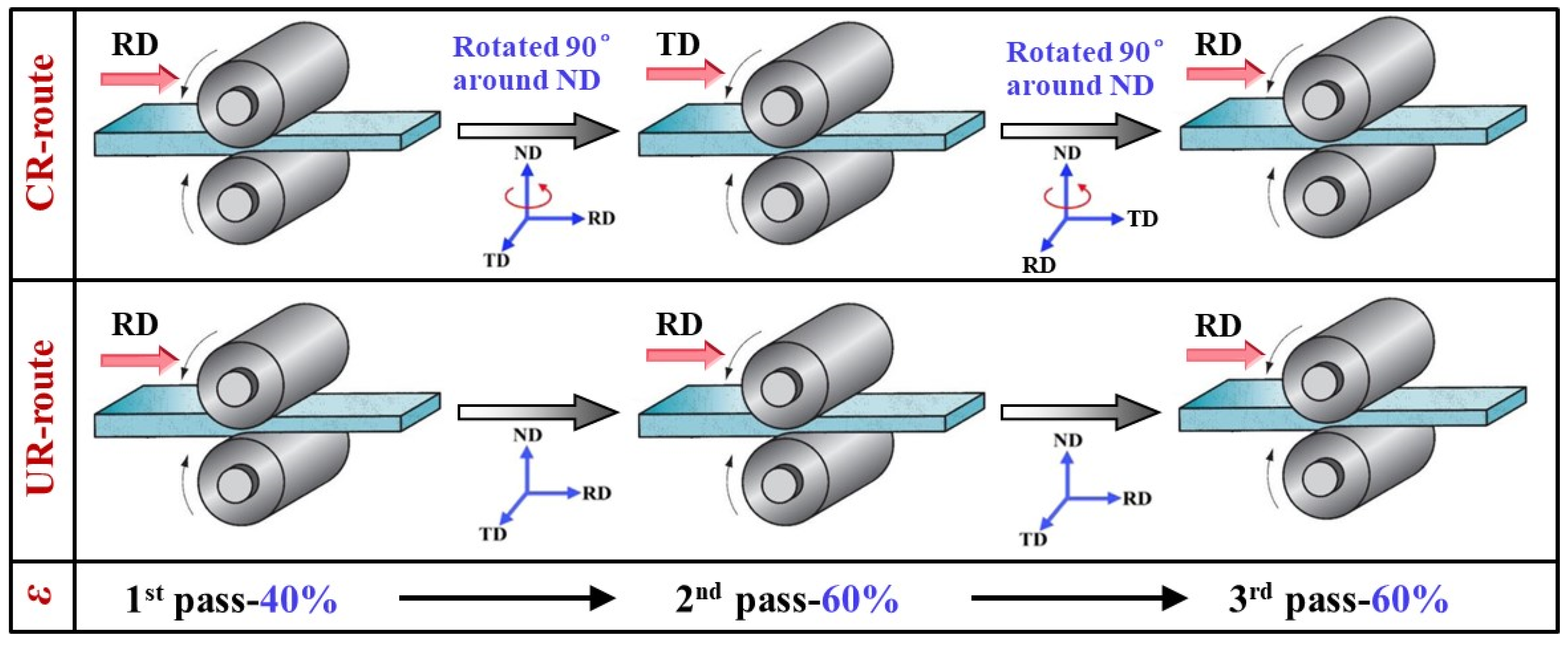
2.3. Unidirectional and Cross Hot Rolling of As-Cast Plate

The rolling specimens were cut out from the internal region of micoralloyed samples with the same sampling method. Subsequently, the rolling direction (RD) was parallel to the length direction and was marked clearly on the original specimens. A single-stand two-high laboratory mill equipped with work rolls of Φ320 mm was adopted, and the roll temperature was precisely controlled within a range of 150 ± 10 °C by circulating heated oil in the interior, as is shown in Figure 1a.
As schematically illustrated in Figure 2, two different rolling routes were designed. For cross-rolling (CR), the rolling direction was altered by 90° around the ND after each pass, while for unidirectional rolling (UR), it was kept along the initial RD direction for comparison purposes. Before rolling, the CR and UR specimens were all preheated to 380 °C for 2 h under a protective atmosphere of argon. Successive reductions (ε) were set at 40%, 60%, and 60%, respectively; further, a total 90% reduction was achieved. In order to eliminate the residual stress and to ensure the rolling temperature, specimens were annealed at 320 °C for 1 h after the first pass, and then at 270 °C for 2 h after the second pass. The rolled specimens were cooled in water after the final pass. During the rolling process, the rolling speed was maintained at 0.5 m/s.

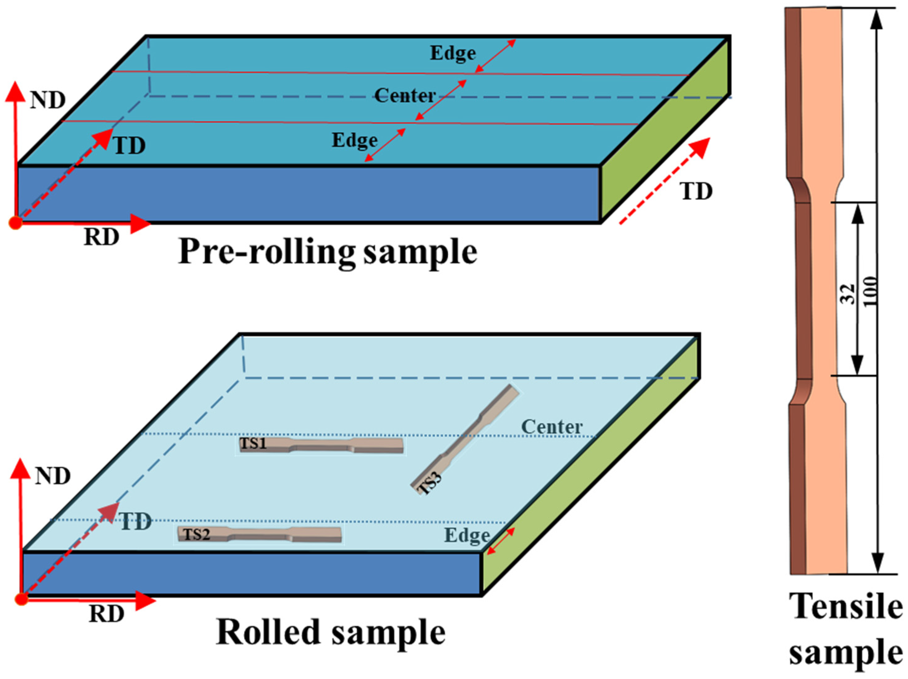
2.4. Microstructure and Mechanical Properties

With reference to the rolling direction during the third pass of rolling, the metallographic and tensile specimens were sampled from the edge region and central region of the finally rolled specimens in order to further investigate the effect of the rolling route on the microstructural and mechanical properties (see Figure 3). The microstructural characteristics of the specimens were analyzed by using optical microscopy (OM) and a ZEISS scanning electron microscope (SEM) equipped with an energy dispersive spectrometer (EDS). The phase compositions were detected using the PANALYTICAL X-ray diffractometer, and then analyzed afterwards with Cu-Kα reflection. The mechanical properties were evaluated by using the dog bone flat tensile specimens that had a gage length of 20 mm and a cross-sectional area of 6 mm × 2 mm. Tensile tests were performed using a CMT5105 electromechanical universal testing machine at a low speed of 1 mm/min at room temperature. The experiments under each condition were repeated three times to improve the accuracy of the results.

3. Results and Discussion

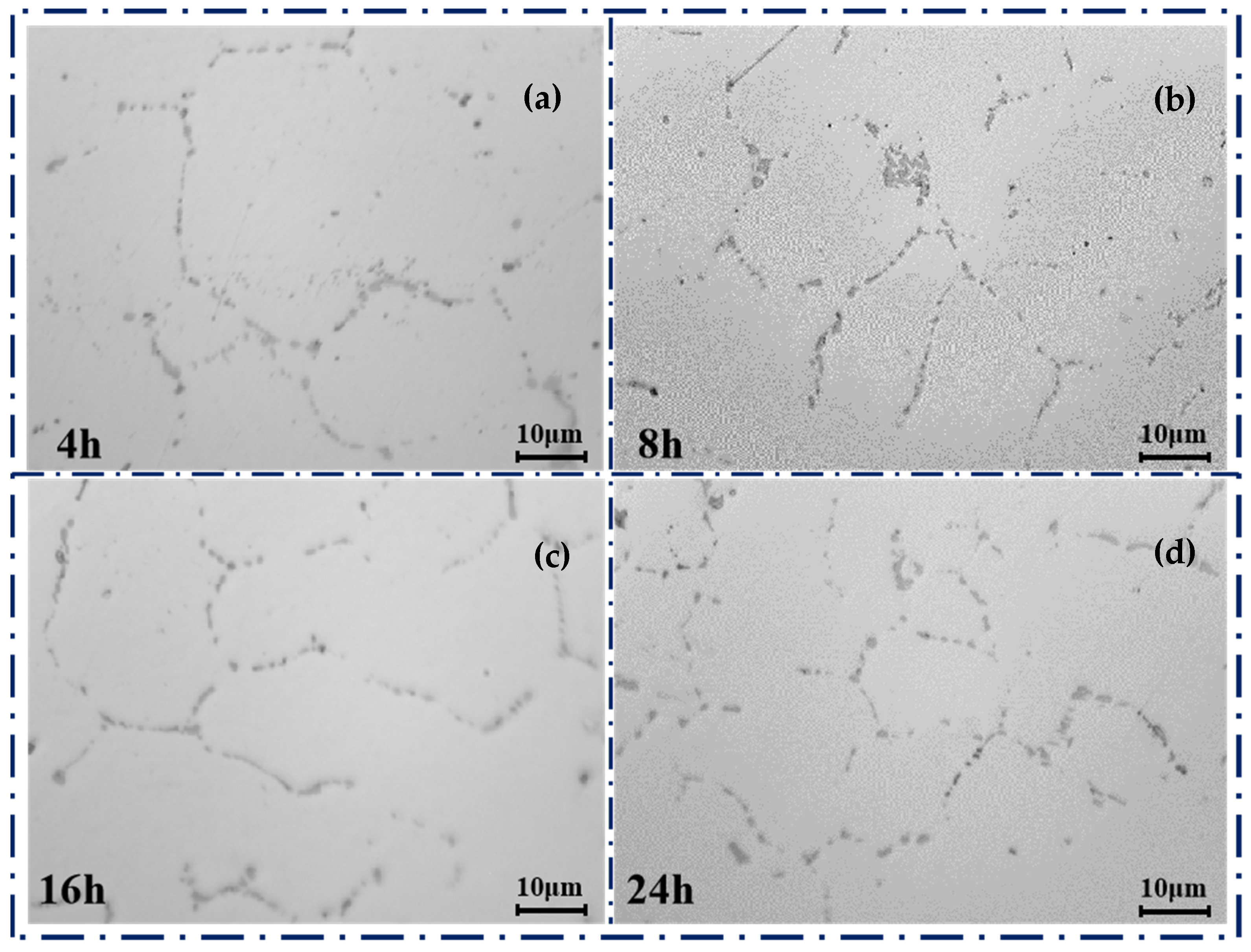
3.1. As-Homogenized Microstructure

The OM images of the as-homogenized AZ31-0.2Ce (wt.%) are shown in Figure 4. When the AZ31-0.2Ce was held at 440 °C, the alloy recrystallized significantly because the homogenization temperature was higher than the recrystallization temperature. As shown in Figure 4, the grains that were added to Ce were significantly refined and equiaxial. An additional second phase was formed due to the addition of the Ce element. When recrystallization occurred, the second phase on the grain boundaries impeded the migration of the grain or subgrain boundaries, thus reducing the rate of migration for the grain or subgrain boundaries [15].
As shown in Figure 4a–d, the original coarse grains (38 µm) became finer (15 µm), and the grain boundaries changed from clear to blurred, while the second phases at the grain boundaries gradually became point-like and continuously distributed with spheroidization. At last, the second phase gradually dissolved into the matrix. With an extension of the holding time, the grain size gradually decreased about 15 µm. At the same time, the precipitated phase at the grain boundary would slowly dissolve [16]. The grain boundaries became clear after homogenizing annealing, as shown in Figure 5. The original granular alloy phase existing between the dendrites was completely solidified into the matrix. In this paper, the AZ31-0.2Ce alloy held at 440 °C for 24 h and was used as the original rolled plate.
The second phase morphology of the alloy after homogenization is shown in Figure 5. Many aggregated second phases were found, as shown in Figure 5a,b, and the difference between pre-rolling and post-rolling was significant. After the original plate was rolled by different processes, the second phase was larger and diffusely distributed with a slight linear trend. The second phase of the rolled plate was smaller and dispersively distributed without aggregation. The uniformity that was shown by the streamlined distribution of the second phase was in the rolling direction.
One of the second phases in a partially continuous mesh was the β-Mg17Al12 phase [17]. In order to determine the detailed chemical composition of the rod-shaped second phase A in Figure 5b, a detailed analysis of the elemental proportions was performed by way of an energy dispersion spectrum; in addition, Mg, Al, Zn, and Ce were found to be the major elements.
The XRD patterns of the as-homogenized AZ31-0.2Ce are shown in Figure 6. For the specific composition of the rod-like second phase, the XRD analysis showed that the second phase was the Al4Ce phase. As shown in Figure 5a, the rod-like Al4Ce phase was denser than the β-Mg17Al12 phase, and was mostly distributed in strips. This was because the β-Mg17Al12 phase was a strengthening phase in the Mg alloy, while the Al4Ce phase was a high-temperature phase. During the solidification of the magnesium alloy, it was easy to proceed due to the small energy required for the non-equilibrium crystallization of Al4Ce [18]. The Al4Ce phase nucleated and firstly grew; then, the β-Mg17Al12 phase nucleated and grew around the Al4Ce phase. Therefore, the Al4Ce rare earth phase was more stable and easier to form than the β-Mg17Al12 phase. Since the formation of the Al4Ce phase consumed a large amount of Al element in the alloy, the length of the β-Mg17Al12 phase was reduced. As a result, both the number and the size of the originally partially continuous reticulate β-Mg17Al12 phases were reduced.
As shown in Figure 5a,c, the second phases were obviously broken and sparse after rolling. At the same time, the Al4Ce phase was obviously distorted when rolled. There was high dislocation density and relatively large grain boundary orientation difference in the distortion region, where it became the core of recrystallization and increased the nucleation rate. Therefore, the Al4Ce phase was used as a nucleation core for the dynamic recrystallization (DRX) procedure during the rolling process. The increase in thermodynamically stable Al4Ce particles also provided more nucleation cores for DRX grains, thus refining the grains. There was almost no presence of a second phase at the grain boundaries because its continuity was also interrupted after multiple rolling passes, and it gradually became diffusely distributed in the α-Mg matrix [19].

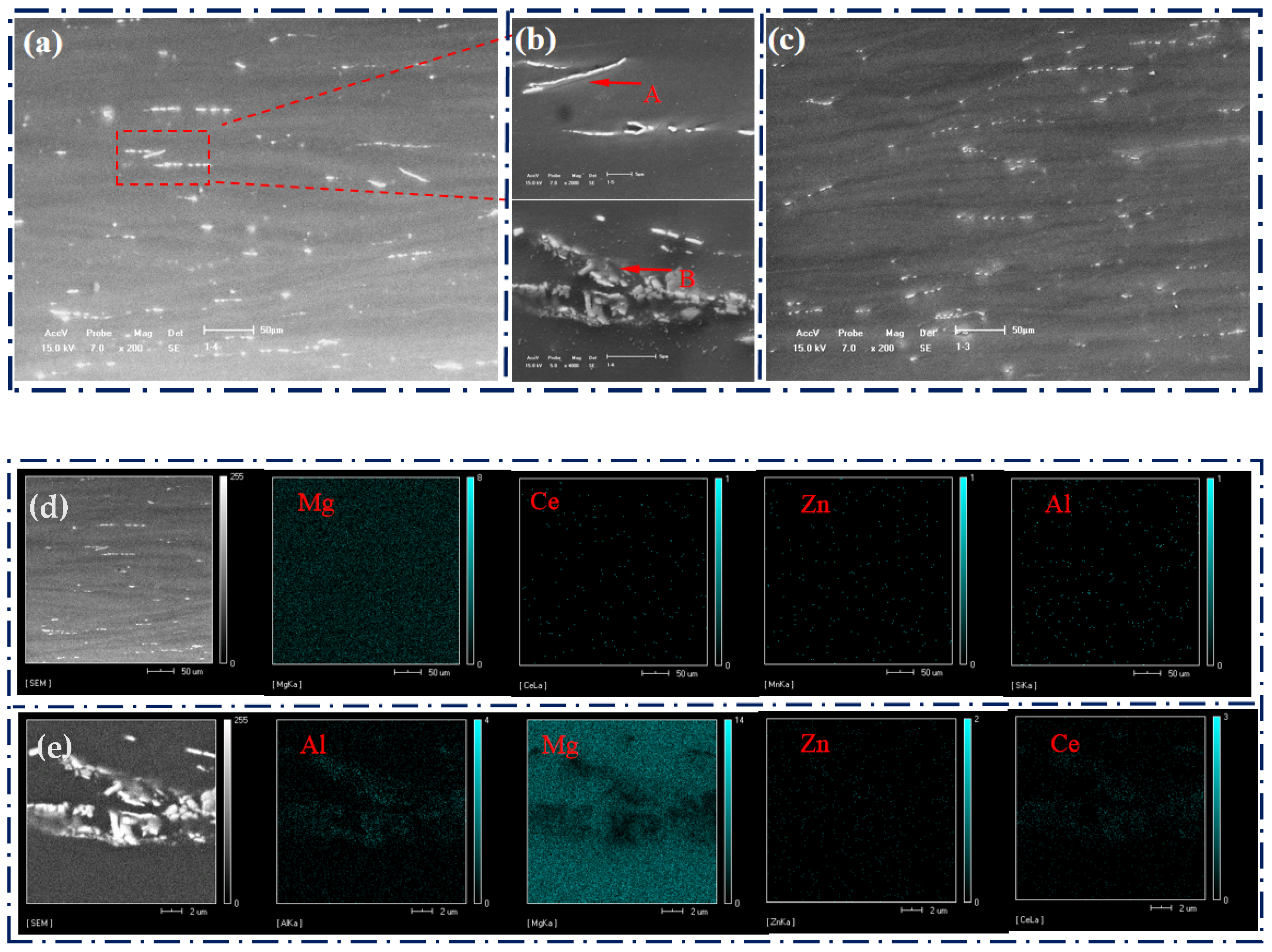
3.2. Microstructure Characteristics

As shown in Figure 7, Figure 8 and Figure 9, different degrees of recrystallization occurred during plate rolling, resulting in different grain sizes and microstructure uniformity [20]. To illustrate the statistical nature of the grain size, further understanding of the grain deformation mechanism under different rolling conditions was required. The cross-sectional (RD-TD) microstructure is shown in Figure 7 as an example. The center microstructure at the surface was more uniform than the edge microstructure. There were more recrystallized grains bowed out at the grain boundaries, and most of the grains were equiaxed and refined crystals. The grains of the center part were larger than the edge recrystallized grains. The recrystallized grains size was concentrated at the level of 4–9 µm due to the higher temperature in the center of the plate rolling, which induced the growth of grains and accounted for 62.25% of the volume fraction (see Figure 10). However, the grain size of the UR-rolled plate became larger due to the high recrystallization growth.
For example, the longitudinal section (ND-RD) microstructures showed that the grains at the edge of the plate were finer than the grains at the center, as shown in Figure 8. For the center part, the finer grains were mainly distributed around the original grain boundaries with large area recrystallization, so the difference in the grain size was not significant. For the edge part, there were more fine grains crosswise distributed in bands from the surface to the center part in the CR-rolled sheet that had its grain size concentrated at the level of 2–6 µm, and this accounted for 55.75% of its volume fraction (see Figure 8). However, for the heart part, there were obvious coarse and non-equiaxial crystals in the UR-rolled sheet, resulting in poor uniformity. The grain size was concentrated at the level of 2–8 µm with a volume fraction of 38.55% (see Figure 8). Therefore, the CR-rolled grains were more homogeneous.
The microstructures of the transverse section (ND-TD) are shown in Figure 9. The grains at the edge of the plate were also finer and more uniform than the grains at the center. For the center, the newly refined grains were mainly distributed around the original grain boundaries that were without extensive recrystallization, so the grain size varied widely. For the edge, there were fine grains crossing in bands around the larger grains from the surface to the center in the CR-rolled plate and its grain size concentrated at the level of 2–9 µm, and this accounted for its size to a percentage of 65.35% (see Figure 9). However, there was no corresponding phenomenon in the UR-rolled plate, and it was scattered around the larger grains, resulting in poor uniformity. The grain size was concentrated at the level of 2–8 µm with a 22.75% volume fraction (see Figure 9). Therefore, the grains in the CR-rolled plate were more homogeneous. In summary, the results revealed that CR rolling with a large reduction in multi-pass rolling conditions could effectively strengthen the homogeneity, spheroidize the grain structure, and reduce the difference of the grain orientation distribution in the plate.

3.3. Tensile Mechanical Properties

The tensile mechanical properties of the plate in different directions after unidirectional and cross rolling are shown in Figure 11. After the unidirectional and cross rolling of the AZ31-0.2Ce alloy sheet, the tensile strength and elongation at the center of the sheet under CR rolling were 263 MPa and 20.7%, respectively. However, the tensile strength and elongation under UR rolling were 268 Mpa and 17.5%, respectively.
At the edge of the sheet, the tensile strength of the CR rolling was 270 MPa and the elongation was 14.2%. However, the tensile strength and elongation under UR rolling were 276 MPa and 12.9%, respectively. The elongation of the CR-rolled sheet was 1.3% higher than that of the UR-rolled sheet at the edge, but the strength was 6 MPa lower. This is because the uniformity of the CR-rolled sheet along the rolling direction was stronger than for the UR-rolled sheet, and the degree of recrystallization growth was higher, resulting in the CR-rolled sheets’ low strength but good plasticity. In the transverse direction of the plate, the tensile strength under CR rolling was 262 MPa, and the elongation was 14.6%. Meanwhile, the tensile strength and elongation after UR rolling were 257 MPa and 12.2%, respectively.
After the conventional rolling process, the crack tip of the sheet was sharper than that of the CR-rolled sheets; in addition, it was easier to extend to the central part of the sheet. The proportion of grain boundaries increased after grain refinement, which augmented the resistance to crack propagation. The edge of the sheet was subjected to shear stress in different directions during CR-rolling, which increased the number of shear bands and provided plentiful nucleation particles for the recrystallization of the edge microstructure. It was beneficial due to the grain refinement and edge processing performance improvements. Therefore, in the transverse part of the sheet with CR rolling, the elongation was 2.4% higher and the strength was 5 MPa higher than with UR rolling.
Figure 12 shows the tensile fracture morphology of the plates in different directions after unidirectional and cross rolling procedures. It could be seen that the fracture was mainly composed of dimples, cleavage steps, and cleavage planes that would belong to a mixed ductile-brittle fracture. For the RD-center tensile specimen (TS1), the fracture morphology after CR rolling showed a mass of dimples with a deep depth, which showed it was a typical ductile fracture. However, although the surface of the UR-rolling fracture was slightly rough with a tearing phenomenon, it was still dominated by dimples and had a ductile fracture tendency. Therefore, the elongation of the CR rolling at the center of the plate was 3.2% higher than that of the UR rolling.
For the RD-edge tensile specimen (TS2), there was a rough surface in the fracture morphologies after CR rolling with tearing phenomena in the dimples, which were shallow and unevenly distributed. However, in the fracture diagrams after UR rolling, there were more tearing edges in the material. Additionally, the dimples were few in number and shallow in depth. Therefore, the elongation of the CR rolling at the edge of the sheet was 1.3% higher than that of the UR rolling.
For the TD tensile specimen (TS3), the fracture map after CR rolling showed obvious edges and corners in the alloy fracture with a small number of shallow dimples. This was characterized by a mixed fracture with brittleness. However, in the fracture map after UR rolling, the fracture morphology of the alloy was mainly composed of many tearing edges, cleavage surfaces, and a small number of extremely shallow dimples, which were obvious brittle fractures. As a result, the elongation of CR rolling in the transverse direction of the sheet was 2.4% higher than that of UR rolling.
In all of the above fracture images, the small particles at the bottom of the dimples were mainly in the Al4Ce alloy phase. The tiny dispersed Al4Ce compounds reduced the duration of the β-Mg17Al12 phase so that the grain size could also be refined to increase the strength and plasticity of the AZ31-0.2Ce alloy. The difference of anisotropy became larger, and the uniformity of metal forming was also different under different rolling methods, which can lead to more tearing edges in the fracture, dimple density reduction, and the particles becoming gradually coarser. The particles or net-like precipitates generated stress concentration during the stretching process, and the particles crushed would cause instability and fracture [13]. The fracture type of the alloy gradually changed to a type of brittle fracture, in which the coarse grain size of the granular and network compound were the main cause of the brittleness and low elongation of the alloy. The analysis of these fracture morphologies on the other hand confirmed that the plasticity of the alloy under different rolling conditions were consistent with the previous analysis results for the stress–strain or elongation curves.

4. Conclusions

The present study attempted to investigate the high-performance of Mg alloy sheets when under multi-pass unidirectional and cross hot rolling procedures after TRC for the purposes of lowering edge defects and energy consumption. The effect of the rolling parameters on the microstructural and mechanical responses of Ce when microalloying AZ31 was performed using UR and CR, respectively. The following conclusions could be drawn from the study.
(1)
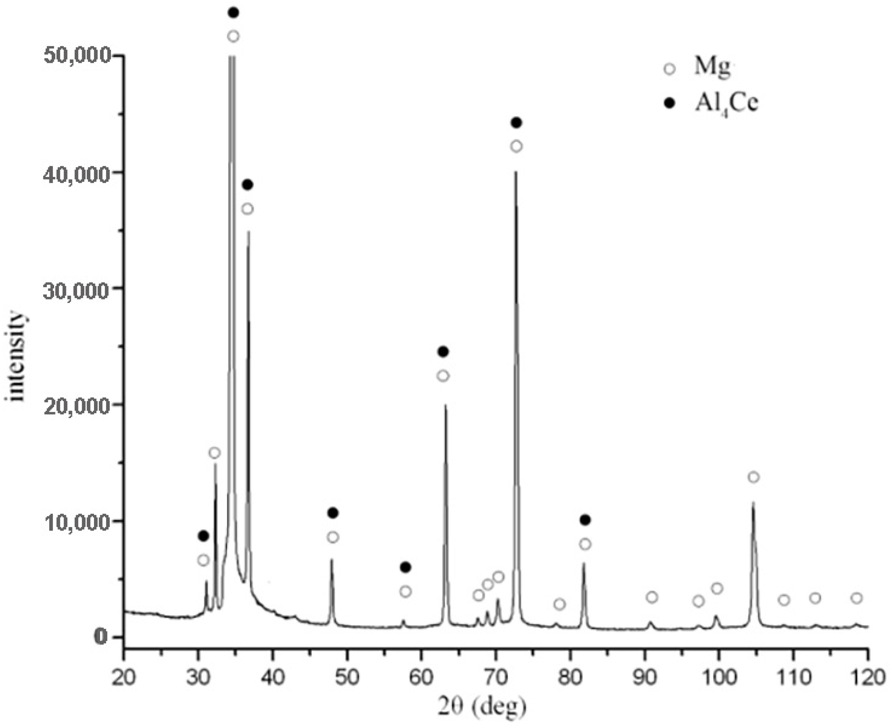
The homogenization effect of the AZ31-0.2Ce alloy is at its best after being kept at 440 °C for 24 h. The Al4Ce phase in the AZ31-0.2Ce alloy sheet disappears at the grain boundary after UR and CR rolling;
(2)
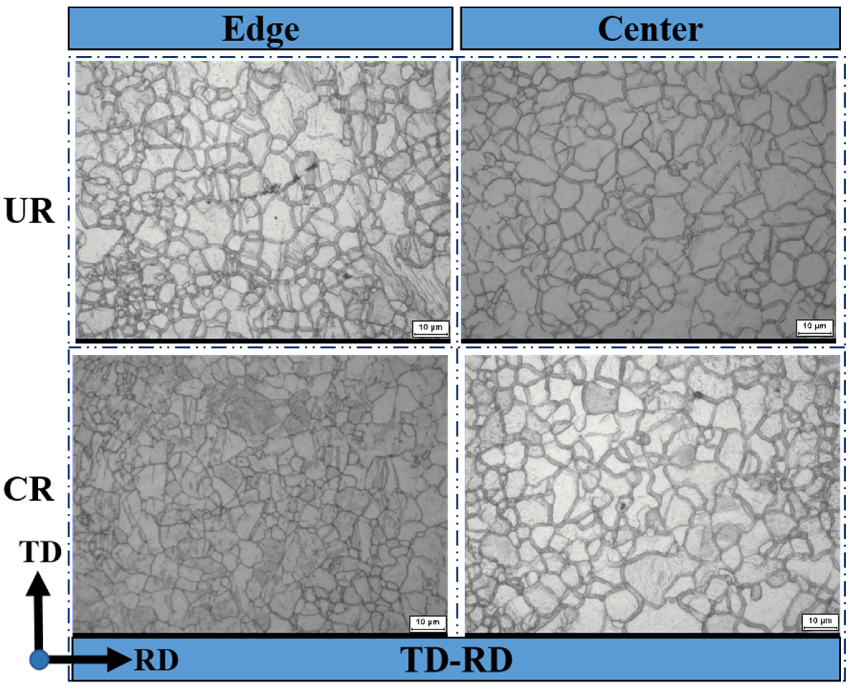
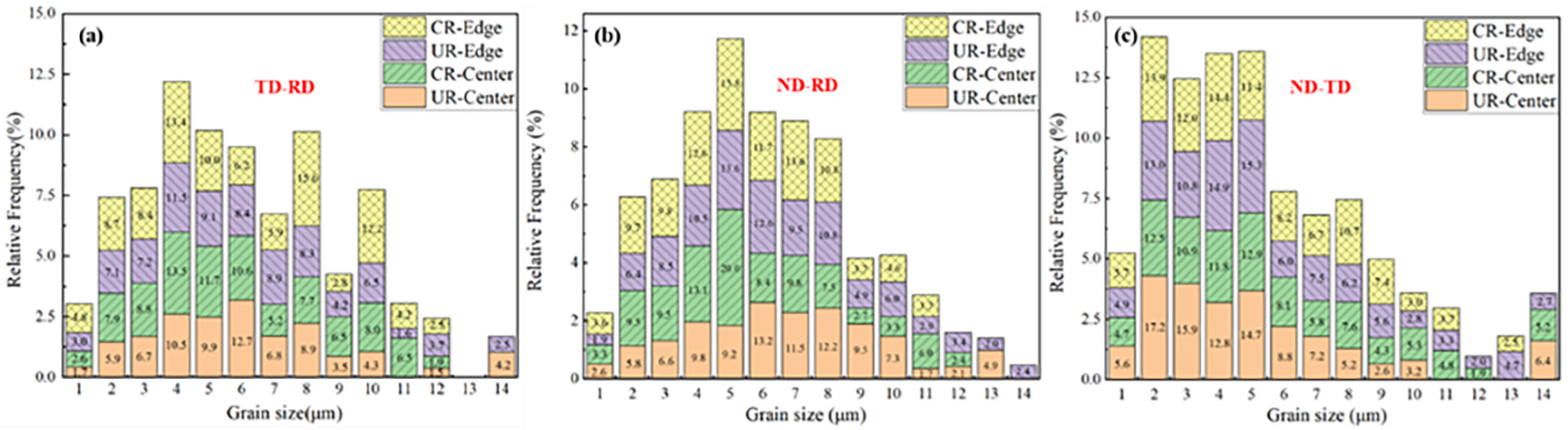
The CR-rolled sheet has a more uniform and finer microstructure in the horizontal and center (average size 5 μm), while for the UR-rolled sheet, it is on the opposing edges (average size 10 μm);
(3)
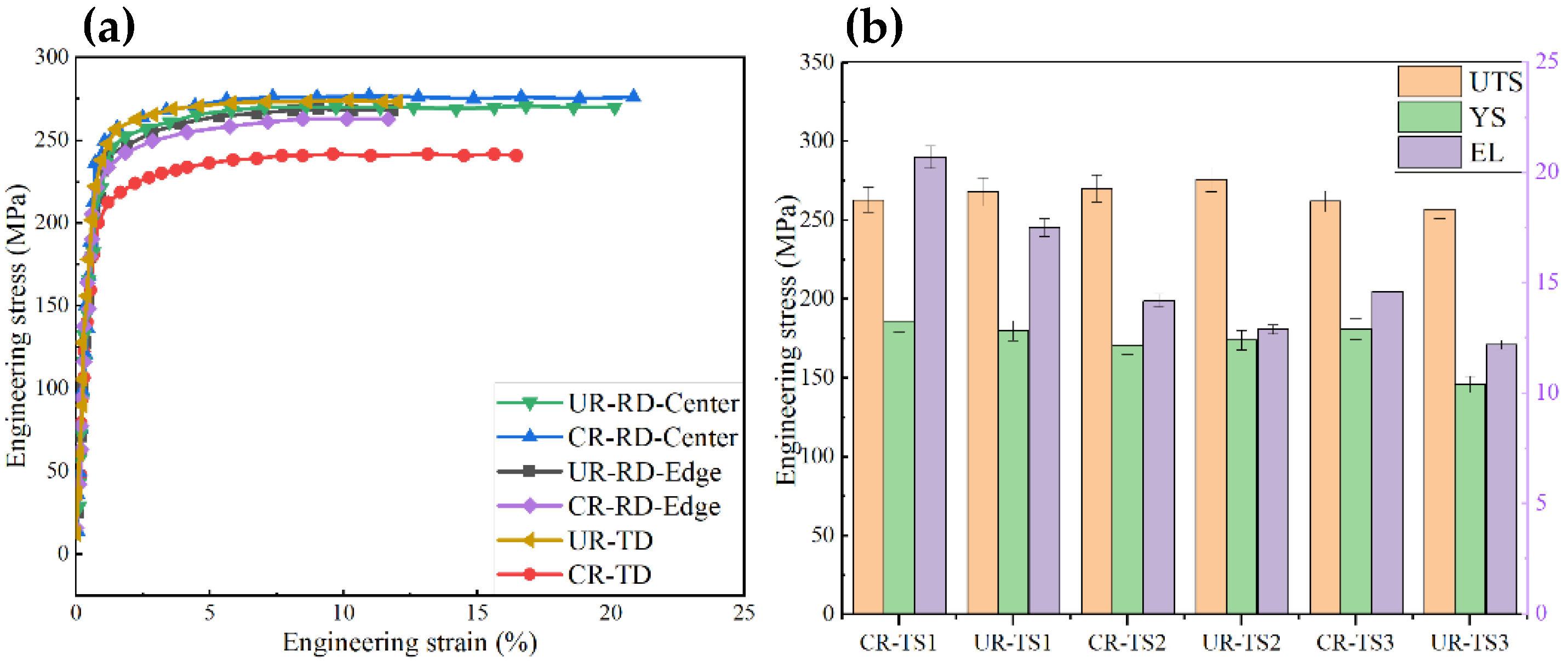
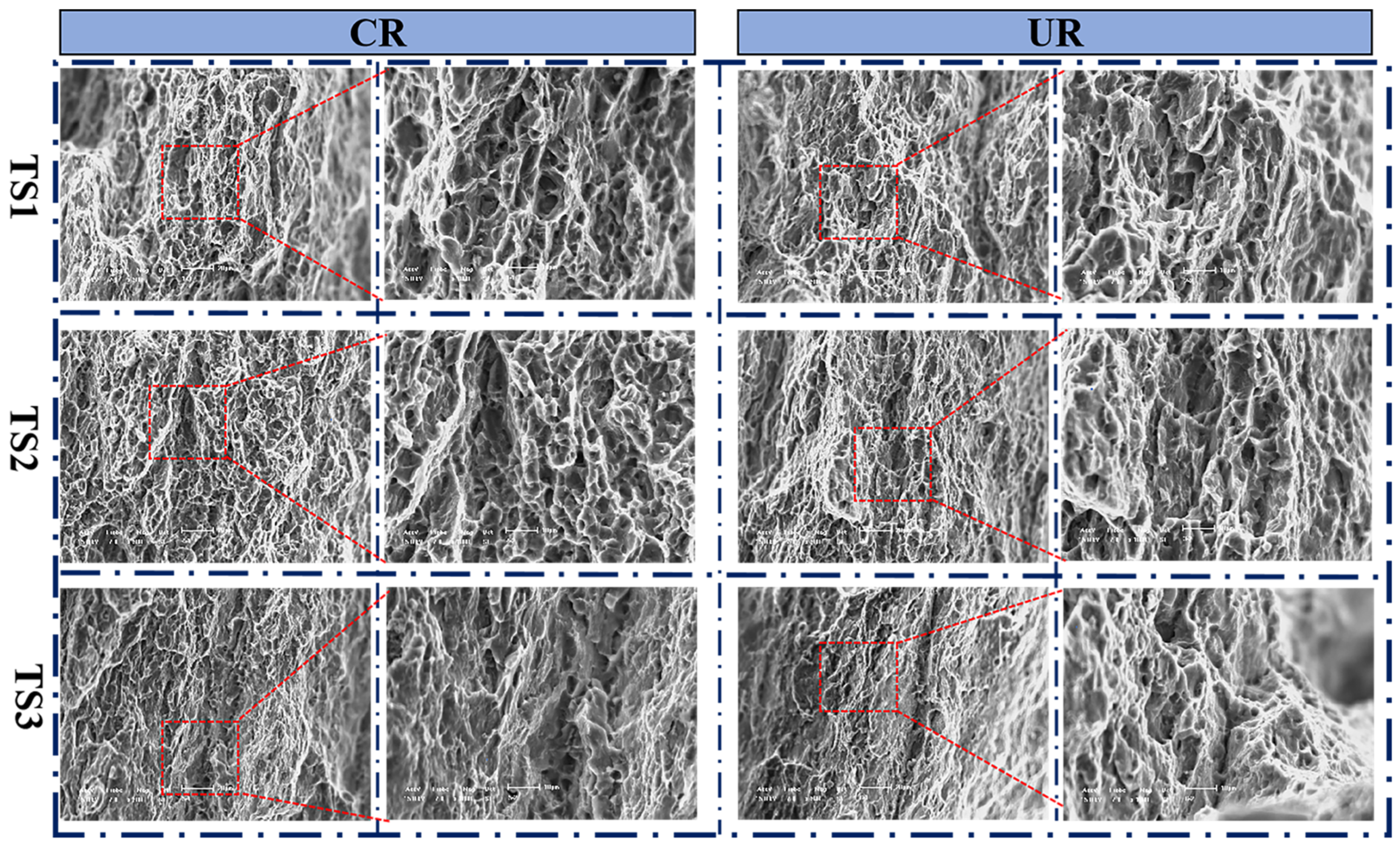
The small particles at the bottom of the dimples, in terms of fracture morphology, were mainly in the Al4Ce alloy phase, which can refine the grain size from 38 μm to 15 μm, and can increase the strength and plasticity of the AZ31-0.2Ce alloy.

Author Contributions

F.N., W.J. and X.C. were in charge of the whole trial; F.N. and S.K. wrote the manuscript; W.J. revised the English of this manuscript. All authors have read and agreed to the published version of the manuscript.

Funding

This research was funded by the Basic Research Program of Shanxi Province [No. 202203021212298], the Key Research and Development Program of Shanxi Province [No. 202102050201005], the National Natural Science Foundation of China [No. 52105388], Taiyuan University of Science and Technology Scientific Research Initial Funding [No. 20222007 & 20222099], Supported by Program for the Innovative Talents of Higher Education Institutions of Shanxi (PTIT) and Supported by Scientific and Technologial Innovation Programs of Higher Ed-ucation Institutions in Shanxi [No. 2022L276). And The APC was funded by [20222007 & 20222099].

Data Availability Statement

Not applicable.

Conflicts of Interest

The authors declare no conflict of interest.

References

  1. Yang, C.M.; Zhang, D.F.; Ding, P.D.; Pan, F.S. The Microstructure and Processing in Twin Roll Casting of Magnesium Alloy Strip. Mater. Sci. Forum 2005, 488–489, 427–430. [Google Scholar] [CrossRef]
  2. Jiang, W.; Wang, J.; Zhao, W.; Liu, Q.; Jiang, D.; Guo, S. Effect of Sn Addition on the Mechanical Properties and Bio-Corrosion Behavior of Cytocompatible Mg-4Zn Based Alloys. J. Magnes. Alloys 2019, 7, 15–26. [Google Scholar] [CrossRef]
  3. Zheng, X.; Du, W.; Liu, K.; Wang, Z.; Li, S. Effect of Trace Addition of al on Microstructure, Texture and Tensile Ductility of Mg-6Zn-0.5Er Alloy. J. Magnes. Alloys 2016, 4, 135–139. [Google Scholar] [CrossRef]
  4. Cao, P.; StJohn, D.H.; Qian, M. The Effect of Manganese on the Grain Size of Commercial AZ31 Alloy. Mater. Sci. Forum 2005, 488–489, 139–142. [Google Scholar] [CrossRef]
  5. Nakaura, Y.; Watanabe, A.; Ohori, K. Microstructure and Mechanical Properties of AZ31 Magnesium Alloy Strip Produced by Twin Roll Casting. Mater. Trans. 2006, 47, 1743–1749. [Google Scholar] [CrossRef]
  6. Tang, W.; Huang, S.; Li, D.; Peng, Y. Mechanical Anisotropy and Deep Drawing Behaviors of AZ31 Magnesium Alloy Sheets Produced by Unidirectional and Cross Rolling. J. Mater. Process. Technol. 2015, 215, 320–326. [Google Scholar] [CrossRef]
  7. Li, Q.; Huang, G.J.; Huang, X.D.; Pan, S.W.; Tan, C.L.; Liu, Q. On the Texture Evolution of Mg-Zn-Ca Alloy with Different Hot Rolling Paths. J. Magnes. Alloys 2017, 5, 166–172. [Google Scholar] [CrossRef]
  8. Pan, S.; Xin, Y.; Huang, G.; Li, Q.; Guo, F.; Liu, Q. Tailoring the Texture and Mechanical Anisotropy of a Mg–2Zn–2Gd Plate by Varying the Rolling Path. Mater. Sci. Eng. A 2016, 653, 93–98. [Google Scholar] [CrossRef]
  9. Wang, Q.; Jiang, B.; Liu, L.; Yang, Q.; Xia, D.; Zhang, D.; Huang, G.; Pan, F. Reduction per Pass Effect on Texture Traits and Mechanical Anisotropy of Mg–Al–Zn–Mn–Ca Alloy Subjected to Unidirectional and Cross Rolling. J. Mater. Res. Technol. 2020, 9, 9607–9619. [Google Scholar] [CrossRef]
  10. Du, Y.; Zheng, M.; Jiang, B. Comparison of Microstructure and Mechanical Properties of Mg-Zn Microalloyed with Ca or Ce. Vacuum 2018, 151, 221–225. [Google Scholar] [CrossRef]
  11. Yu, K.; Li, W.; Zhang, S. Mechanism of Grain Refining by Adding Cerium in Mg and Mg Alloys. RARE Met. Mater. Eng. 2005, 34, 1013–1016. [Google Scholar]
  12. Chino, Y.; Kado, M.; Mabuchi, M. Compressive Deformation Behavior at Room Temperature—773 K in Mg–0.2 Mass%(0.035at.%)Ce Alloy. Acta Mater. 2008, 56, 387–397. [Google Scholar] [CrossRef]
  13. Zhu, Y.; Hu, M.; Wang, D.; Xu, H.; Wang, Y.; Ji, Z. Microstructure and Mechanical Properties of AZ31-Ce Prepared by Multipass Solid-Phase Synthesis. Mater. Sci. Technol. 2018, 34, 876–884. [Google Scholar] [CrossRef]
  14. Li, Y.; He, C.; Li, J.; Wang, Z.; Wu, D.; Xu, G. A Novel Approach to Improve the Microstructure and Mechanical Properties of Al–Mg–Si Aluminum Alloys during Twin-Roll Casting. Materials 2020, 13, 1713. [Google Scholar] [CrossRef]
  15. Chaubey, A.K.; Scudino, S.; Prashanth, K.G.; Eckert, J. Microstructure and Mechanical Properties of Mg–Al-Based Alloy Modified with Cerium. Mater. Sci. Eng. A 2015, 625, 46–49. [Google Scholar] [CrossRef]
  16. Shang, L.; Jung, I.H.; Yue, S.; Verma, R.; Essadiqi, E. An Investigation of Formation of Second Phases in Microalloyed, AZ31 Mg Alloys with Ca, Sr and Ce. J. Alloys Compd. 2010, 492, 173–183. [Google Scholar] [CrossRef]
  17. Pan, H.; Xie, D.; Li, J.; Xie, H.; Huang, Q.; Yang, Q.; Qin, G. Development of Novel Lightweight and Cost-Effective Mg–Ce–Al Wrought Alloy with High Strength. Mater. Res. Lett. 2021, 9, 329–335. [Google Scholar] [CrossRef]
  18. Zhang, C.; Wu, L.; Huang, G.; Liu, K.; Pan, F. Influence of Microalloying with Ca and Ce on the Corrosion Behavior of Extruded Mg-3Al-1Zn. J. Electrochem. Soc. 2019, 166, 445–453. [Google Scholar] [CrossRef]
  19. Li, W.; Zhou, H.; Lin, P.; Zhao, S. Microstructure and Rolling Capability of Modified AZ31–Ce–Gd Alloys. Mater. Charact. 2009, 60, 1298–1304. [Google Scholar] [CrossRef]
  20. Huang, X.; Suzuki, K.; Chino, Y. Static Recrystallization Behavior of Hot-Rolled Mg-Zn-Ce Magnesium Alloy Sheet. J. Alloys Compd. 2017, 724, 981–990. [Google Scholar] [CrossRef]
Figure 1. Two high laboratory mills for the Mg alloy sheets [14]. (a) Schematic of the twin-roll casting process; (b) forced-cooling technology.
Crystals 13 00841 g001
Figure 2. Schematic diagrams of the cross and unidirectional rolling with different reductions per pass.
Crystals 13 00841 g002
Figure 3. Sampling method of the metallographic and tensile specimens.
Crystals 13 00841 g003
Figure 4. OM diagram of the as-cast Mg alloy after homogenization at a high temperature of 440 °C for diverse periods of time: (a) 4 h; (b) 8 h; (c) 16 h; and (d) 24 h.
Crystals 13 00841 g004
Figure 5. SEM images of the AZ31-0.2Ce alloy in different states after homogenization treatment: (a) pre-rolling condition, (b) locally enlarged image. (c) post-rolling condition; and (d,e) SEM micrograph of the secondary phases and EDS analysis of the A and B points.
Crystals 13 00841 g005
Figure 6. The X-ray diffraction spectra (XRD) images of the as-homogenized AZ31-0.2Ce alloys.
Crystals 13 00841 g006
Figure 7. Microstructures along the TD-RD direction at the edge and center of the sheet after one-way and cross-rolling processes.
Crystals 13 00841 g007
Figure 8. Microstructures along the ND-RD direction at the edges and cores of the sheet after one-way and cross-rolling processes.
Crystals 13 00841 g008
Figure 9. Microstructures along the ND-TD direction at the edges and cores of the sheet after one-way and cross-rolling processes.
Crystals 13 00841 g009
Figure 10. Grain statistics of the OM diagrams of plates in different directions after unidirectional and cross rolling: (a) TD-RD, (b) ND-RD, and (c) ND-TD.
Crystals 13 00841 g010
Figure 11. Tensile mechanical properties of the plate in different directions after unidirectional and cross rolling: (a) engineering stress-strain curves, (b) UTS, YS and EL values.
Crystals 13 00841 g011
Figure 12. Tensile fracture morphology of the plate in different directions after unidirectional and cross rolling procedures.
Crystals 13 00841 g012
Table 1. Chemical compositions for the micoralloyed AZ31-0.2Ce (wt.%).
AlZnMnCeSiFeMg
2.820.9880.260.2060.0420.001Bal.
Disclaimer/Publisher’s Note: The statements, opinions and data contained in all publications are solely those of the individual author(s) and contributor(s) and not of MDPI and/or the editor(s). MDPI and/or the editor(s) disclaim responsibility for any injury to people or property resulting from any ideas, methods, instructions or products referred to in the content.

