Article

Reflections of High-Frequency Pulsed Ultrasound by Underwater Acoustic Metasurfaces Composed of Subwavelength Phase-Gradient Slits

Department of Mechanical Engineering, National Yunlin University of Science and Technology, Yunlin, Douliou 64002, Taiwan
*
Author to whom correspondence should be addressed.
Crystals 2023, 13(5), 846; https://doi.org/10.3390/cryst13050846
Submission received: 25 April 2023 / Revised: 17 May 2023 / Accepted: 17 May 2023 / Published: 20 May 2023

Abstract

:
We numerically and experimentally investigated the behavior of high-frequency underwater ultrasounds reflected by gradient acoustic metasurfaces. Metasurfaces were fabricated with a periodic array of gradient slits along the surface of a steel specimen. The finite element method was adopted for the acoustics–structure interaction problem to design the metasurfaces and simulate the reflected fields of the incident ultrasound. Our metasurfaces yielded anomalous reflection, specular reflection, apparent negative reflection, and radiation of surface-bounded modes for ultrasonic waves impinging on the metasurfaces at different incident angles. The occurrence of these reflection behaviors could be explained by the generalized Snell’s law for a gradient metasurface with periodic supercells. We showed that at some incident angles, strong anomalous reflection could be generated, which could lead to strong retroreflection at specific incident angles. Furthermore, we characterized the time evolution of the reflections using pulsed ultrasound. The simulated transient process revealed the formation of propagating reflected ultrasound fields. The experimentally measured reflected ultrasound signals verified the distinct reflection behaviors of the metasurfaces; strong anomalous reflection steering the ultrasound pulse and causing retroreflection was observed. This study paves the way for designing underwater acoustic metasurfaces for ultrasound imaging and caustic engineering applications using pulsed ultrasound in the high-frequency regime.

1. Introduction

Metamaterials can manipulate and control waves in ways that are not possible for conventional materials [1,2]. For example, negative refractive index materials that offer possibilities for imaging and the control of waves at subwavelength scales can be realized through metamaterials [3,4,5]. Over the past decade, inspired by fascinating capabilities achieved by metamaterials, a family of two-dimensional (2D) artificial materials known as metasurfaces has rapidly emerged [6,7]. These metasurfaces enable manipulation of the propagation of optical and acoustic waves in nonconventional ways by introducing the generalized Snell’s law for classical waves [8]. The ability to tailor efficient and diverse interfacial acoustics–structure interactions makes acoustic metasurfaces particularly suitable for manipulating sound in air and water [9,10]. The first application of metasurface analogy can be traced to Alberich anechoic layers for efficient underwater sound absorption and insulation [11,12,13,14]. Pioneering studies have also revealed that acoustic metasurfaces are promising materials for controlling sound and have led to innovative applications via their extraordinary wave behaviors [15,16,17,18]. In general, acoustic metasurfaces are composed of artificially tailored subwavelength units capable of providing non-trivial local phase shifts to engineer the wavefront or phase profile of impinging waves. Numerous types of units (also referred to as meta-atoms), such as Helmholtz resonators, labyrinthine structures, helical structures, coiling-up spatial structures, and membrane structures, have been designed to build functional acoustic metasurfaces [19,20,21,22,23]. With these engineered meta-atoms, the associated metasurfaces can passively reconstruct fascinating wavefront profiles, including acoustic beam focusing, beam self-bending, acoustic vortex, sound diffusing, asymmetric transmission, and acoustic carpet cloaking [24,25,26,27,28,29].
Therefore, phase-gradient acoustic metasurfaces with unique beam-steering properties have attracted considerable attention. Gradient metasurfaces are formed by periodic arrays of supercells with closely packed meta-atoms and varying geometric parameters. To achieve the desired wavefront steering, the spatial phase gradient of the supercell must be carefully modulated in accordance with the generalized laws of reflection and refraction. Using the aforementioned meta-atom designs arranged in a supercell, the phase gradient can be implemented by accumulating a phase shift based on tuning the propagation path or controlling the phase delay of the resonances [30,31].
Rich physical effects are enabled by acoustic-gradient metasurfaces through distinct arrangements and designs of the supercell and meta-atoms. According to the generalized Snell’s law, a critical angle of the incident wave exists that defines the domain in which anomalous reflection can occur. Beyond the critical angle, the metasurfaces transform incident waves into surface-bounded modes [32]. Moreover, the reflection by acoustic-gradient metasurfaces must simultaneously comply with the grating theory owing to the supercell periodicity [33]. The condition of the periodic arrangement of the supercell along the surface plane changes the impulsion of the incident wave such that the wave energy may be diffracted as Floquet modes of different orders than the surface-bounded mode. The combined effects of the gradient metasurfaces thus allow realization of acoustic retroreflection and apparent negative reflection.
Most existing studies on acoustic metasurfaces have demonstrated acoustic responses at the time-harmonic states, showing steady-state fields with continuous sinusoidal incident waves in the low-frequency regime (0.1–10 kHz). However, many applications, such as non-destructive evaluation and medical ultrasound treatments, utilize pulsed ultrasound [34,35]. To benefit these potential applications, we demonstrate an underwater acoustic gradient metasurface operating in the high-frequency regime (0.5 MHz) in this study. Slit structures are utilized as meta-atoms owing to their simple configuration and accessibility for fabricating meta-atoms of reduced sizes with sufficient accuracy. Using pulsed ultrasound, we reveal wave-steering and splitting features, which exhibit the wave information of the transient processes and behaviors of an ultrasonic pulse impinging on the metasurfaces. We focus on the underwater reflection behavior of gradient-type metasurfaces. Anomalous reflection, retroflection, negative reflection, surface-bounded propagation, and energy splitting of an incident ultrasonic pulse by our acoustic gradient metasurface are investigated and discussed. The results of this study are expected to have some potential applications to the efficient search for an underwater ultrasound source via passive detection of local acoustic pressure of the reflected field and production of a desired underwater ultrasound field by one or more located sources through the extraordinary reflection of the metasurface [36,37].
To validate the underwater acoustic gradient metasurfaces operating in the high-frequency regime, pulsed ultrasound experiments are conducted. The efficiency and resolution of the gradient metasurfaces depend strongly on the level of discretization in the supercell. Good control of the phase change along the metasurface requires a dense array of fine meta-atoms. However, the structures are difficult to scale down using conventional fabrication approaches. To overcome this problem, we employ wire electrical discharge cutting (WEDC) to fabricate closely packed fine-slit meta-atoms on the sub-millimeter scale.

2. Materials and Methods

2.1. Structure and Finite Element Modeling Approach

Schematics of the underwater acoustic metasurface with subwavelength phase-gradient silts are shown in Figure 1. The meta-atom is composed of stainless steel and has a slit of width w and depth h1 with a circular bottom. The lattice constant is denoted as a. The impinging ultrasound is transformed into a propagative waveguide mode in the slit, and the waveguide mode radiates back to the water as a reflected wave. Therefore, the slit depth is tailored to produce the desired local phase shift in the reflected wave. To fully consider the acoustics–structure interaction, the steel domain is assumed to be an elastic solid. Thus, the entire unit–cell model can be divided into solid and fluid parts with a coupling interface.
Here, the finite element (FE) method is employed to design the gradient metasurfaces and simulate the transient propagation of the pulsed ultrasound in the system. An FE formulation of the acoustics–structure interaction problems is adopted [38,39]. The weak form corresponding to the governing equation of the acoustic pressure, p, in the fluid domain, Ωf, is given by the following:
Ω f v f ( 2 p t 2 c 0 2 T p ) d V = 0 ,
where vf is a weight function, c0 is the speed of sound in water, and is the gradient operator in vector matrix form. In the FE solution approach, the model is meshed adaptively according to variations in the fluid domain and divided into small elements connected by nodes. Therefore, the pressure field and weight function are approximated by the standard FE discretization as follows:
p = N f p , v f = N f c f ,
where Nf is the matrix of the fluid element shape functions, p is the vector matrix containing the nodal pressures, and cf is the matrix of the nodal weights. By applying Gauss’s divergence theorem and substituting Equation (2) into Equation (1), the FE formulation can be obtained as follows after some manipulation:
Ω f N f T N f d V p ¨ + c 0 2 Ω f ( N f ) T N f d V p = c 0 2 Ω f N f T n f T p d S .
In Equation (3), nf is the unit outward normal vector and n f T p is a scalar function that describes the boundary conditions imposed on the domain boundary, Ω f .
For elastic wave propagation in the solid domain, Ωs, the weak form is associated with Cauchy’s equation of motion and is given by the following:
Ω S v s T ( ˜ T σ ρ s 2 u s t 2 + b ) d V = 0 ,
where vs is the vector weight function, σ is the Cauchy stress tensor, us is the elastic displacement vector, b is the body force, ρs is the mass density of the solid, and ˜ is the strain differential operator matrix. The elastic stress, σ, is related to the displacement, us, by Hooke’s law as follows:
σ = D ˜ u s ,
where D is the elastic stiffness matrix. Analogously, Equation (4) can be rewritten as an FE formulation:
Ω s N s T ρ s N s d V d ¨ + Ω s ( ˜ N s ) T D ˜ N s d V d = Ω s N s T σ n s d S + Ω s N s T b d V .
In this equation, d is the vector matrix containing the nodal displacements defined by the discretization us = Nsd, and Ns is the matrix of the solid-element shape functions. The term σns in the surface integral is a vector function that describes the imposed boundary conditions, in which ns is the unit outward normal vector of the domain boundary, Ω s .
At the boundary between the solid and fluid domains, denoted as Ω sf , the normal displacement and pressure are continuous. By introducing n = nf =ns, the continuity conditions at the coupled boundary are given by the following:
u s n = u f n ,
σ n = p n .
In Equation (7), uf is the fluid displacement. Its second time derivative (acceleration of the fluid particles) is related to the pressure as follows:
p = ρ f u ¨ f
where ρf is the fluid density. Using Equations (7) and (9), the boundary force term in Equation (3) acting on the fluid can be rewritten as follows:
c 0 2 Ω f N f T n f T p d S = ρ f c 0 2 Ω sf N f T n T N s d S d ¨ + c 0 2 Ω f N f T n f T p d S ,
where the first term on the right-hand side represents the force exerted on the fluid by the solid at the coupled boundary and Ω f denotes the uncoupled fluid domain boundary. Similarly, using Equation (8), the boundary force term in Equation (6) acting on the solid can be rewritten as follows:
Ω s N s T σ n s d S = Ω sf N s T n N f d S p + Ω s N s T σ n s d S ,
where the first term on the right-hand side represents the force exerted on the solid from the fluid side at the coupled boundary and Ω s denotes the uncoupled solid domain boundary. Substituting Equation (10) into Equation (3) and Equation (11) into Equation (6), a system of coupled second-order time-dependent differential equations of motion in terms of the FE formulation can be obtained. This system is written in the abbreviated matrix form as follows:
[ M s 0 ρ f c 0 2 H T M f ] ( d ¨ p ¨ ) + [ K s H 0 K f ] ( d p ) = ( F s F f ) ,
where
M s = Ω s N s T ρ s N s d V ,
K s = Ω s ( ˜ N s ) T D ˜ N s d V ,
M f = Ω f N f T N f d V ,
K f = c 0 2 Ω f ( N f ) T N f d V ,
H = Ω sf N s T n N f d S ,
F s = Ω s N s T b d V + Ω s N s T σ n s d S ,
F f = c 0 2 Ω f N f T n f T p d S .
Equation (12) is suitable for simulating the transient process of the coupled system. To solve this equation, a direct integration method in the time domain can be applied. The basic procedure is to sub-divide the response period time, T, into N intervals of time step Δt = T/N and then determine the solution of the equilibrium equation at each step. When the external excitation is a time-harmonic with an angular frequency ω, the dynamic equilibrium equation of the acoustics–structure coupled system in the steady state can be expressed as follows:
[ K s ω 2 M s H ρ f c 0 2 ω 2 H T K f ω 2 M f ] ( d ¯ p ¯ ) = ( F s F f ) ,
where d ¯ and p ¯ are the amplitudes of the time-harmonic nodal displacements and pressures, respectively.

2.2. Numerical Implementation

We implement the numerical calculations using the commercial FE solver package COMSOL Multiphysics [40]. The acoustic pressure and structural mechanics interfaces are used simultaneously to solve the acoustics–structure coupled system. To design the gradient metasurface, we first calculate the scattered acoustic pressure field of the periodic system with uniform meta-atoms excited by normally incident plane waves. Subsequently, we gradually change the slit depth to determine the complete phase variation. Accordingly, we can construct the phase-gradient supercell of the metasurface by tailoring the slit depth of each meta-atom. Because of the spatial periodicity of the system, the Floquet boundary condition is applied to one unit at the side boundaries. At the top side of the water domain and bottom side of the solid domain, perfectly matched layers (PMLs) are applied as extended domain boundaries to absorb the outgoing waves. By solving the coupled equations with the boundary conditions, the steady-state response of the time-harmonic reflected wave field is obtained.
To obtain the transient response of the underwater gradient metasurface, we build full-wave models containing sufficient supercells and solve them using the time-dependent coupled equations given in Equation (12). We establish a line source with a specified incident angle to launch a directional Gaussian ultrasound pulse that impinges on the designed metasurface. The ultrasound pressure pulse is expressed as follows:
p pulse ( x , y , t ) = p 0 ( t ) e α ( ( x x 0 ) 2 + ( y y 0 ) 2 ) ,
where α is the spatial decay factor, (x0, y0) are the coordinates of the line source center, and p0(t) is the pulse amplitude with a center angular frequency ω and is given as
p 0 ( t ) = p 0 e γ ( t T 0 β ) 2 sin ω t ,
where γ is the temporal decay factor, T0 is the mean pulse time, and β is a factor that defines the pulse duration. To yield satisfactory numerical convergence in our simulations, the discretized time step is set as Δt = T/N = 2π/ωN with N = 20. Moreover, to cope with the outgoing wave radiation in the model of finite extent, artificial plane-wave radiation and low-reflection conditions are imposed on the corresponding boundaries of the fluid and solid domains, respectively.

2.3. Fabrication and Experimental Method

We consider the metasurface operating at a frequency of 0.5 MHz, which corresponds to a wavelength of approximately 3 mm in water. To achieve sufficient efficiency and resolution of the gradient metasurface, the scale of the corresponding meta-atom must be an order of magnitude smaller than the wavelength of the acoustic pressure, i.e., in the sub-millimeter regime. In this study, we employ WEDC to fabricate gradient metasurfaces on stainless steel specimens. The metal wire used for cutting is made of copper with a diameter of 250 μm, which is able to manufacture a sequence of sufficiently narrow slits and spacing to form the metasurface.
In the experiments, we send ultrasound pulses and measure the ultrasound signals reflected by the underwater gradient metasurface in a water tank. Two identical immersion ultrasonic transducers with a center frequency 0.5 MHz (A391S-SU, Olympus, Shinjuku, Tokyo, Japan) are utilized to emit and receive the ultrasound signals. The two transducers are appropriately positioned and oriented above the metasurface for the measurements. A pulser–receiver (5072PR, Panametrics, Billerica, MA, U.S.A.) is used to generate a high-voltage pulse that is sent to the emitting transducer to excite the ultrasound pulse. The ultrasound pulse radiates into the water to impinge on the underwater metasurface, and the reflected signal is detected by the receiving transducer and recorded using a digital oscilloscope.

3. Results and Discussion

3.1. Design of the Ultrasonic Underwater Gradient Metasurfaces

The gradient metasurface introduces local gradient-phase modulation and non-local periodicity of the supercell array. Accordingly, the generalized Snell’s law that describes the reflection of the metasurface can be expressed as follows [33,41]:
k 0 ( sin θ r sin θ i ) = d ϕ d x + G n ,
where k0 is the wavenumber, θi is the incident angle, θr is the reflected angle, dφ/dx is the designed phase gradient in which φ is the position-dependent phase along the metasurface, and Gn is the reciprocal lattice vector originating from the non-local supercell periodicity. We utilize a meta-atom with a slit as the building block to construct reflecting gradient metasurfaces. Two meta-atom designs with different pitches (a = 592 and 540 μm) are considered. Figure 2a shows the calculated reflected phase variation as a function of the slit depth using normally incident background plane waves, where the slit width w = 360 μm. For the w/a ratios considered, the phase varies approximately linearly with the slit depth. Increasing the lattice pitch, a, increases the nonlinearity of the phase dependence on the slit depth. Figure 2b illustrates the scattered pressure field in water of ten meta-atoms with linearly varying phase modulation in the complete 2π range for the case of a = 592 μm. We stress that the resulting reflection behavior via the metasurfaces is frequency (or wavelength λ) dependent. First, the generalized Snell’s law with non-vanishing phase gradient and reciprocal lattice vector states that the reflection is dependent on the wavelength (in terms of k0 = 2π/λ). This means that incident waves with a different frequency will be reflected into a different angle. Moreover, the phase gradient /dx of the metasurfaces also changes at a different frequency because the meta-atom shifts the reflected phase differently. These effects lead to the frequency dependence of the reflection behavior of the metasurfaces.
To consider the influence of the phase gradient, we have built two different supercells (designs I and II) using meta-atoms with a = 592 and 540 μm, respectively, following the strategy of phase profile engineering. Table 1 lists the arrangement of the meta-atoms and the corresponding slit depths for the two supercell designs. The resulting supercell periods in designs I and II are as = 5920 μm (with 10 meta-atoms) and 4320 μm (with 8 meta-atoms), respectively, and the corresponding design values of the phase gradient, dφ/dx, are 0.5 k0 and 0.6852 k0, respectively. According to Equation (23), design I yields a critical angle θc,0 = 30° for the anomalous reflection when n = 0. For design II, the critical angle is θc,0 = 18.35°. Beyond the critical angle, a surface-bounded mode may emerge. Simultaneously, Equation (23) allows higher-order diffraction. These higher-order diffractions may encounter additional critical angles. These critical angles play a crucial role in the resulting distinctive reflection behavior of the metasurfaces. In the following section, we systematically discuss the underwater reflection behavior of the two designed gradient metasurfaces using the results obtained from the frequency-response and transient simulations.

3.2. Reflected Wave Manipulation via Underwater Phase-Tuning Slits

Figure 3 shows the calculated scattered pressure fields for plane waves impinging on the infinite metasurface of design I at various incident angles. The results exhibit distinct reflection behaviors for different incident angles, which involve diffractions of different orders. For θi < θc,0 = 30°, the reflected pressure field is mostly dominated by the diffraction of order n = 0 of Equation (23), which results from the gradient-phase modulation. However, when the incident angle is negative and sufficiently large, the diffraction of order n = −1—which corresponds to the conventional Snell’s law of reflection—becomes obvious in the reflected pressure field. Consequently, the reflected pressure field exhibits an interference pattern of the two diffracted wave beams. This reveals the decreased efficiency of the anomalous reflection owing to the gradient-phase modulation with n = 0, where an increasing portion of the incident pressure is not converted into the waveguide mode in the slits and directly reflected by the metasurface as specular reflection (i.e., θi = θr) when the incident angle increases. When the incident angle exceeds the critical angle (i.e., θi > θc,0), a dramatic change in the reflected angle is observed. The reflected pressure field becomes dominated by the diffraction of orders n = −3 and −4, in which apparent negative reflection arises. Similarly, when the incident angle further increases above the critical angle, the diffraction of order n = −1 emerges again to take the place of the diffraction of orders n = −3 and −4 in the reflected pressure field.
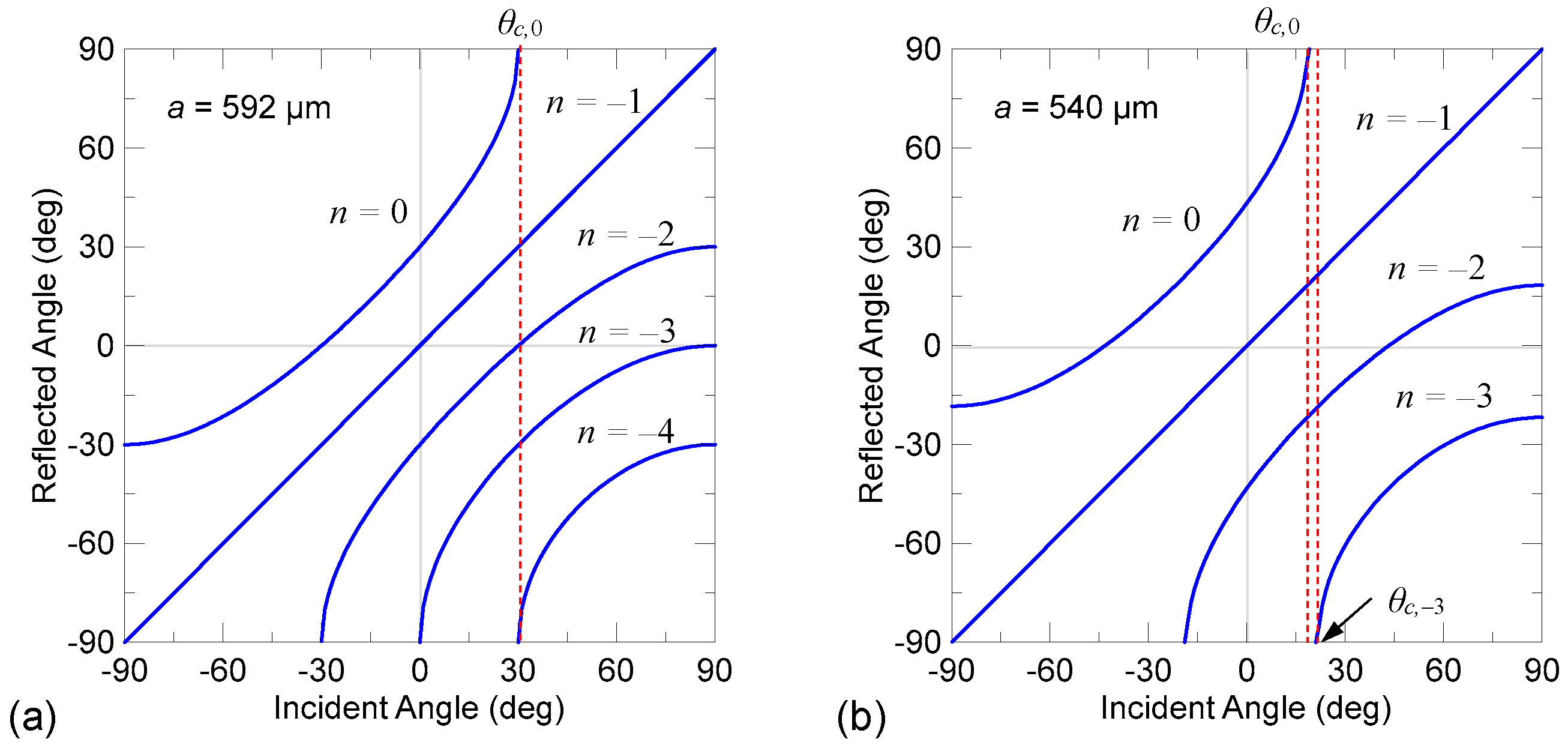
Figure 4a shows the relationship between the reflected and incident angles using Equation (23) with possible orders of diffraction for design I. Intriguingly, although many possible diffraction orders exist, Figure 3 indicates that the gradient metasurface of design I predominately reflects the incident waves only with diffraction orders n = 0, −1, −3, and −4. These highly active diffraction orders correspond to anomalous reflections due to the surface gradient-phase modulation (n = 0), specular reflection at a large incident angle (n = −1), and apparent negative reflection beyond the critical angle, θc,0 (n = −3 and −4). The other possible diffraction orders are much less significant in the resulting reflected pressure fields regardless of the incident angle.
For design II, with dφ/dx = 0.6852 k0, Figure 4b relates the reflected angle to the incident angle via possible diffraction orders. In light of the criteria revealed in design I, the active diffraction orders of design II dominating the reflected pressure fields are n = 0, −1, −2 and −3. These correspond to anomalous reflection due to the surface gradient-phase modulation (n = 0), specular reflection at large incident angles (n = −1), and apparent negative reflection beyond the critical angle (n = −2, −3). To examine these criteria, Figure 5 presents the calculated scattered pressure fields for plane waves impinging on the metasurface of design II at various incident angles. We observe consistent behaviors of anomalous reflection, specular reflection, and apparent negative reflection in relation to the reflected angles predicted in Figure 4b by the corresponding highly active diffraction orders. Moreover, near the two critical angles—θc,0 = 18.35° and θc,–3 = 21.74°—of diffraction orders n = 0 and −3, respectively, the reflected angles change dramatically with the change in the incident angle. When θc,0 < θi < θc,–3, the only allowed diffraction order for the apparent negative reflection is n = −2; therefore, it governs the reflected angle and reflected pressure field. When θi > θc,–3, the diffraction of order n = −3 dominates the reflected pressure field until the incident angle increases and the specular reflection becomes obvious.
To clearly observe the dependence of the reflected acoustic pressure distributions of different diffraction orders on the incident angle for the two supercell designs, Figure 6 and Figure 7 show the steady-state full-wave results when a directional acoustic Gaussian beam (beam width wb ≈ 7 as) impinges on the two metasurfaces of the finite supercells. 
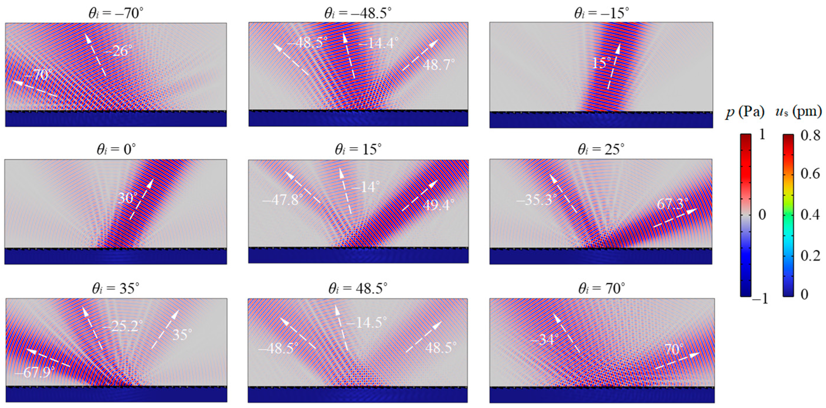
Figure 6 corresponds to the metasurface of design I and illustrates the reflected fields for the Gaussian beam with incident angles θi = −70°, −48.5°, −15°, 0°, 15°, 25°, 35°, 48.5°, and 70°. We observe the evolution of the reflected beams caused by the different orders of diffraction when the incident angle is varied. From the reflected fields, we observed that the subwavelength meta-atom is sufficiently small to lead to negligible distorting effect on the reflected beams by the roughness of the slits. The acoustic pressure reconstructs smooth wavefront profiles in a short distance (within 1 or 2λ) from the grooving metasurface. When the incident angle is negative and as large as θi = −70°, the diffractions of orders n = 0 and −1—which correspond to anomalous and specular reflections, respectively—are strong. Reducing the incident angle to θi = −48.5° weakens the specular reflection and enhances the anomalous reflection. When the incident angle is further decreased to θi = −15°, only the anomalous reflection occurs to form a perfect retroreflection with an exact θr = 15°. Anomalous reflection dominance is observed in the incident angle range of θi = −15° to 15°. Increasing the positive incident angle to θi = 25°, the diffraction of order n = −3 that corresponds to the apparent negative reflection clearly emerges in addition to the anomalous reflection. For incident angle θi = 35°, which is beyond the critical angle of θc,0 = 30°, the diffraction of order n = 0 is completely suppressed, and two beams of apparent negative reflection corresponding to n = −3 and –4 simultaneously occur to dominate the reflection field. When the incident angle reaches θi = 70°, only the apparent negative reflection corresponding to n = −4 survives, along with the emergence of specular reflection.
For the metasurface of design II, the reflected fields for the continuous Gaussian beam with incident angles θi = −70°, −43.3°, −20°, 0°, 15°, 20°, 35°, 43.3°, and 70° are illustrated in Figure 7. The evolution of the reflected beams caused by the different diffraction orders when the incident angle varies is similar to that observed for design I. When the incident angle θi = −70°, diffractions of orders n = 0 and −1—which correspond to anomalous and specular reflections, respectively—are clearly generated. When the incident angle is reduced to θi = −43.3°, the anomalous reflection along the normal direction (θr = 0°) dominates along with minor specular reflection. When the incident angle θi = −20°, strong retroreflection by the diffraction of order n = 0 occurs with an exact θr = 20°. For θi = 0° and 15°, which are still less than the critical angle of θc,0 = 18.35°, anomalous reflection by the diffraction of order n = 0 dominates along with minor specular reflection of n = −1 and apparent negative reflection of n = −2. For θi = 20°, which is in between the two critical angles, θc,0 = 18.35° and θc,–3 = 21.74°, anomalous reflection is suppressed, and apparent negative reflection through diffraction of order n = −2 occurs as the retroreflection. In addition, another obvious beam is observed at a large reflection angle. This reflected beam, corresponding to no diffraction order, originates from the radiation of the surface-bounded mode. When the incident angle is larger than the critical angle of θc,–3 = 21.74°, the diffraction of order n = −3 emerges as an apparent negative reflection and dominates the reflected fields, as shown in the cases of θi = 35° and 43.3°. However, when the incident angle reaches θi = 70°, the apparent negative reflection becomes weak and specular reflection becomes very strong.
We note that diffraction patterns in the reflected fields can be ubiquitously observed in our simulated results (see Figure 6 and Figure 7). The occurrence of the diffraction effects is due to the fact that the metasurfaces are composed of a sequence of subwavelength slits. According to the Huygens–Fresnel principle, diffraction happens when incident waves are reflected by these slit structures. These multiple, closely spaced slits result in complex diffraction patterns of varying intensity. Obvious diffraction patterns can be seen near the edges of reflected main beams. The presence of the diffracted fields can be observed right above the metasurfaces when reflection occurs.

3.3. Time-Resolved Reflected Pulsed Ultrasound Pressure Propagation

To observe the transient process of reflection, the simulated results of the explicit time-dependent underwater ultrasound pulses impinging on the metasurfaces are shown in Figure 8 and Figure 9. An ultrasound pulse with a central frequency of 0.5 MHz is created by a line pressure source (using Equation (21) with α = 5400 m–2, β = 2.4 μs, and 
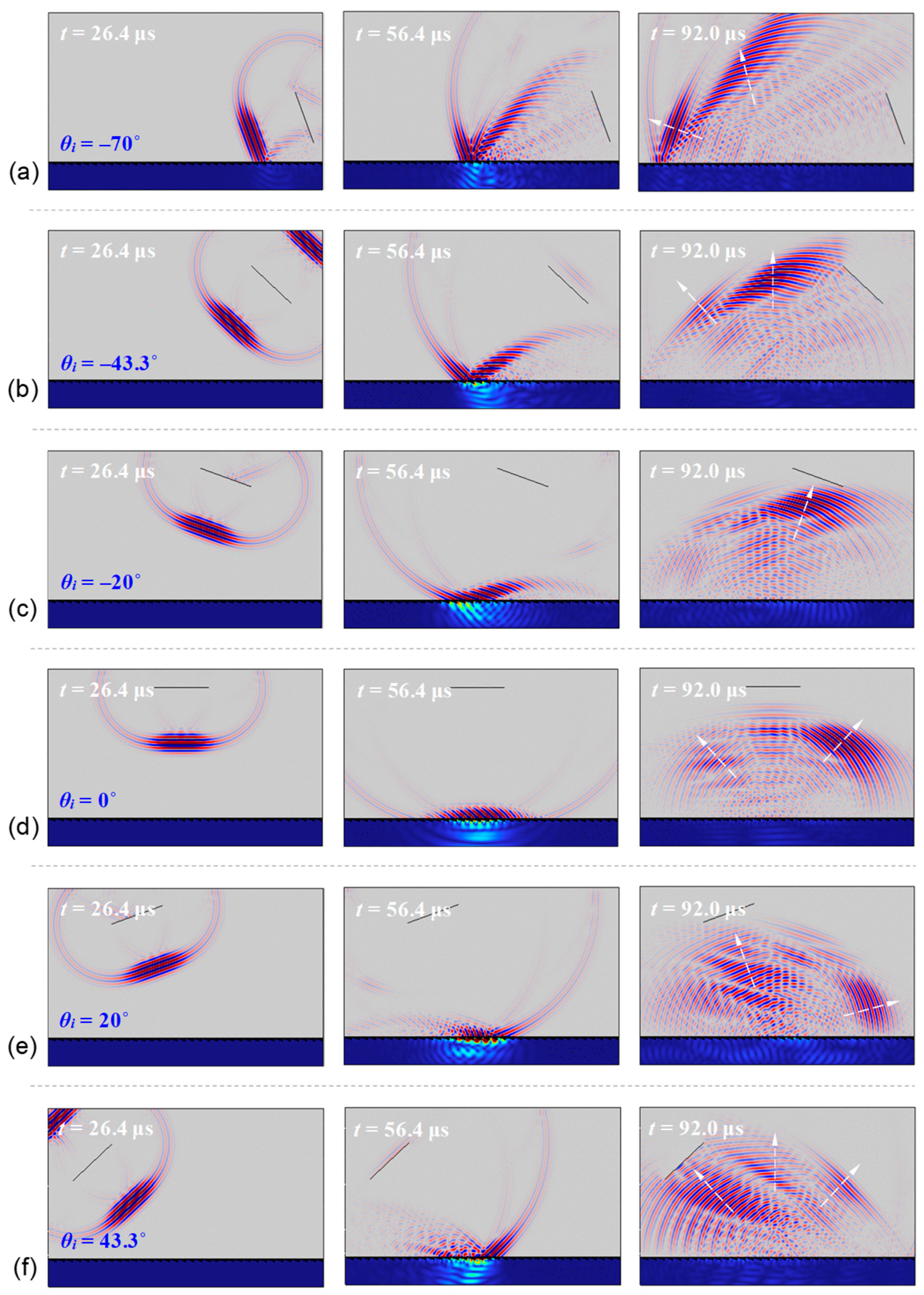
γ = 1) from different incident angles to the metasurfaces. The time duration of the pulse is approximately 10 μs. We begin our discussion with the case of design I in Figure 8, where the simulated reflection processes with incident angles θi = −70°, −15°, 0°, 15°, and 48.5° are illustrated (see also Supplementary Movies S1, S2, S3, S4, and S5). These incident angles are used to characterize the reflection of the ultrasound pulse due to diffraction of different orders. As shown in Figure 8a, when θi = −70°, we observe two obvious energy groups reflected by the metasurface. These are generated by anomalous and specular reflections, and their phases propagate along the directions corresponding to the diffraction of orders n = 0 and –1, respectively. The energy group of the anomalous reflection is severely dispersive along the altitude owing to the large incident angle. In addition, a sequence of delayed weak energy groups that follow behind the first energy group of specular reflection are also observed. We attribute this delayed specular reflection to the discontinuous re-radiation of the multiply reflected waveguiding acoustic pressure in the slits of the metasurface. When θi = −15°, 0°, and 15°, we observe that most of the incident energy is reflected in the direction corresponding to the anomalous reflection (by the diffraction of n = 0), as shown in Figure 8b–d. However, little specular reflection is observed. Owing to their zero or small incident angles, the spatial dispersion of the main reflected energy groups is much smaller. It is noted that for the case of θi = −15°, the main reflected energy group is along the retro-direction of incidence. Figure 8e shows the results for θi = 48.5°. We consider this incident angle because it is predicted to yield an apparent negative reflection (by the diffraction of n = −4) along the retro-direction of incidence. Intriguingly, the simulated transient results show that the energy group of the apparent negative reflection in the retro-direction is highly dispersive. Continuous delayed negative reflection leading to energy group dispersion is observed after the ultrasound pulse impinges on the metasurface. Simultaneously, delayed specular reflection following behind the first energy group of specular reflection also occurs. This again shows that the incident acoustic energy can be temporarily trapped by the waveguiding slits of the metasurface and re-radiate in groups back to the water above after experiencing multiple reflections in the slits. For this incident angle, this effect is considerable.
Figure 9 shows the transient results for the metasurface of design II. The considered incident angles are θi = −70°, −43.3°, −20°, 0°, 20°, and 43.3° (see also Supplementary Movies S6–S11). Overall, we observe similar reflection phenomena to those in design I. When the incident is a large negative value of θi = −70°, diffraction of n = 0 and −1 dominates the reflected field, where the metasurface reflects the incident pulse into two dominant energy groups with phase velocities along the anomalous and specular directions (see Figure 9a). By decreasing the incident angle to θi = −43.3°, the anomalous reflection along the normal direction is enhanced, while the specular reflection is significantly suppressed, as shown in Figure 9b. For θi = −20°, strong retroreflection occurs with relatively little dispersion of the reflected energy group, as shown in Figure 9c. Compared with design I, design II provides a larger incident angle for the occurrence of strong anomalous retroreflection. For normal incidence θi = 0° in Figure 9d, we observe that the anomalous reflection still dominates, accompanied by minimal diffraction of n = −1 and −2 (specular and apparent negative reflection, respectively). When θi = 20°, which is between the two critical angles of θc,0 and θc,–3 (diffraction of n = 0 and −3 is not allowed), a complex reflected field is observed (see Figure 9e). Because this incident angle is beyond the critical angle θc,0, a surface-bounded mode is allowed in this case. Consequently, the reflected field is mainly composed of reflected energy groups along three directions: anomalous reflection along the retro-direction (by diffraction of n = −2), specular reflection with θr = 20° (by diffraction of n = −1), and re-radiation of the surface-bounded mode with an ultra-large reflected angle. For θi = 43.3° shown in Figure 9f, the reflected field is simultaneously governed by the diffraction of n = −1, −2, and −3, and thus, specular reflection and apparent negative reflection along the normal direction and retro-direction are observed. Again, the energy groups of the apparent negative reflection are highly dispersive, and the delayed weak energy groups follow behind the first energy group of the specular reflection.

3.4. Experimental Measurements of Reflected Underwater Pulsed Ultrasound

The experimental specimens of the metasurfaces fabricated using the WEDC method are shown in Figure 10. Ultrasound experiments were conducted underwater with these metasurfaces according to the approach described in 
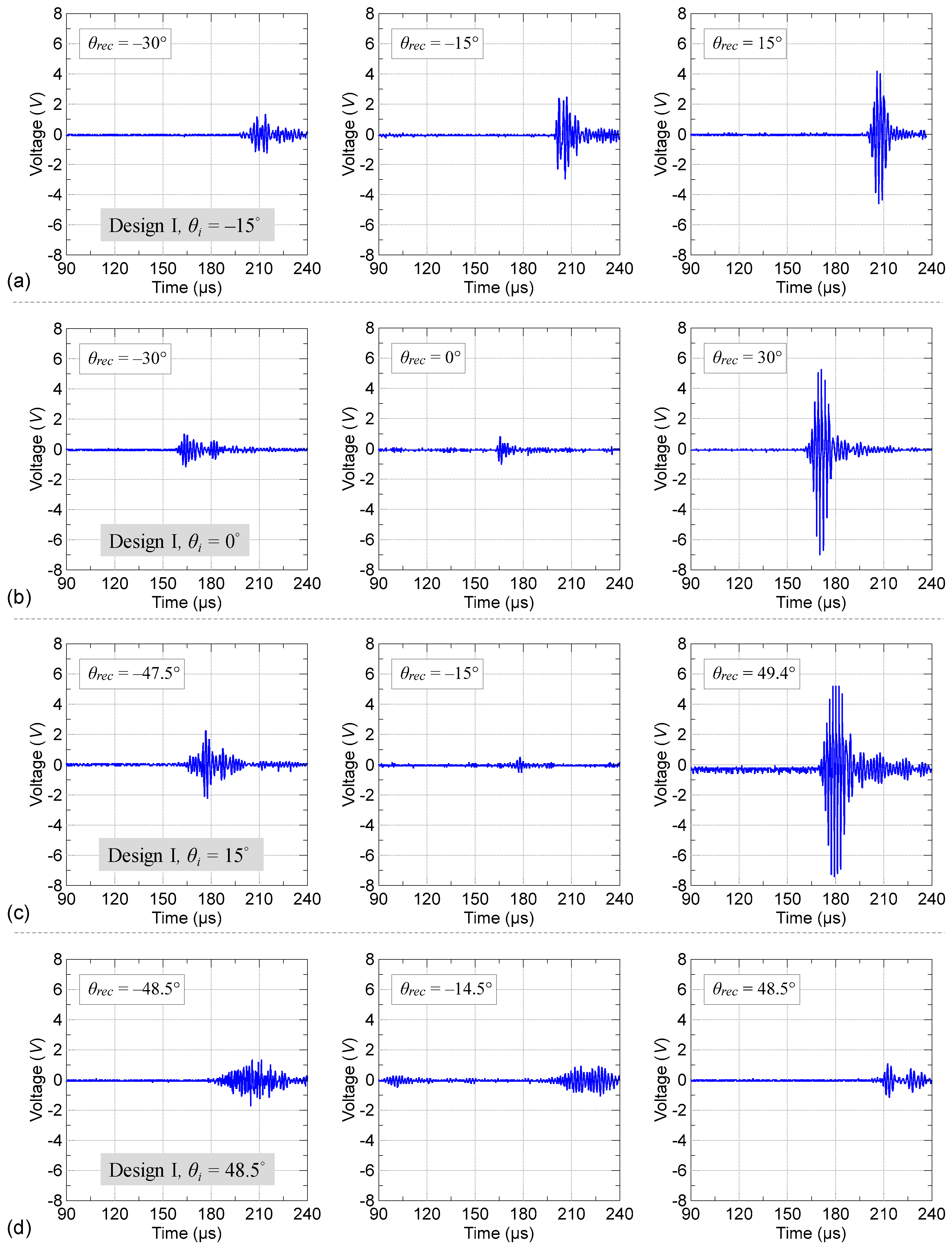
Section 2.3. The time duration of the used pulse is approximately 10 μs in the experiments. For the metasurface of design I, we considered incident angles of θi = −15°, 0°, 15°, and 48.5°. Figure 11 shows the time domain ultrasound signals of the reflection measured by the receiver transducer located at different receiving angles, θrec (the angle from the normal line to the metasurface; clockwise: +, counterclockwise: −). When receiving the signal in the retro-direction of the incident ultrasound pulse, the emitter transducer also serves as a receiver transducer. In these measurements, the origin of time, t = 0 (i.e., the time point of the incident ultrasound pulse being launched) is defined by a trigger signal sent by the pulser–receiver at the same time as the incident ultrasound pulse is launched. When θi = −15°, the signals measured at θrec = −30°, −15°, and 15° are compared in Figure 11a. The results show that the signal due to anomalous reflection (n = 0) along the retro-direction θrec = 15° is the strongest and that the specular reflection along θrec = −15° is secondary. In addition, the signal along the irrelevant receiving angle θrec = −30° is minimal. When θi = 0°, the measured signals at θrec = −30°, 0°, and 30° are compared in Figure 11b. The results show that the signal of anomalous reflection along θrec = 30° is the strongest, whereas the signals along the other two angles are much weaker. When θi = 15°, the strongest signal among all the considered receiving angles is observed along θrec = 49.4°, also originating from the anomalous reflection, as shown in Figure 11c. The secondary signal is due to the emergence of an apparent negative reflection along θrec = −47.5° (n = −3). Figure 11d shows the signals recorded at θrec = −48.5°, −14.5°, and 48.5° when θi = 48.5°. Because this incident angle is beyond the critical angle, θc,0, anomalous reflection is completely suppressed. Instead, the signals of apparent negative reflection along θrec = −14.5° and −48.5° due to diffraction of orders n = −3 and −4 becomes dominant. However, as shown in Figure 8, the distribution of the negative reflection field is spatially dispersive, and thus the measured signals are not as strong as those of the anomalous reflection.
Figure 12 shows the measured reflection signals for the ultrasound pulse at different incident angles impinging on the metasurface of design II. The considered incident angles are θi = −43.3°, −20°, 0°, 20°, and 43.3°. The recorded signals at receiving angles θrec = −43.3°, 0°, and 43.3° for incident angle θi = −43.3° are shown in Figure 12a. Obvious ultrasound signals of the specular reflection (along θrec = −43.3°) and anomalous reflection (along θrec = 0°) are observed. Comparatively, the anomalous reflection signal is stronger than that of the specular reflection. For θi = −20°, we consider receiving angles of θrec = −30°, −20°, and 20°. As shown by Figure 12b, a strong ultrasound signal of anomalous reflection along the retro-direction θrec = 20° is observed, and clear specular reflection is also revealed by the signal along θrec = −20°. In addition, the signal along the irrelevant receiving angle of θrec = −30° is minimal. For θi = 0°, the receiving angles at θrec = −43.3°, 0°, and 43.3° that correspond to diffraction orders n = 0, −1, and −2, respectively, are considered. As shown in Figure 12c, the dominant signals are along θrec = 43.3° due to anomalous reflection by diffraction of n = 0 and along θrec = −43.3° due to specular reflection by diffraction of n = −1. For θi = 20°, Figure 12d shows the reflected signals measured at θrec = −20°, 20°, and 75°. It can be seen that the signal measured along θrec = 75° is strong. As illustrated in Figure 9e, the ultrasound signal measured at a large receiving angle originates from the radiation of the surface-bounded mode. In addition, the signals of retroreflection along θrec = −20° (by diffraction of n = −2) and specular reflection along θrec = 20° (by diffraction of n = −1) are also observed; however, these two signals are weaker than that from the surface-bounded mode. Figure 12e shows the results for θi = 43.3° with θrec = −43.3°, 0°, and 43.3°. These receiving angles correspond to the directions of retroreflection, anomalous reflection, and specular reflection, respectively, and clear signals of the reflected ultrasound are observed. Owing to the spatial dispersion of the reflected wave energy distribution illustrated by the simulated results in Figure 9f, the measured signals exhibit average strengths.

4. Conclusions

We systematically studied the reflection behavior of underwater ultrasound by gradient metasurface. We considered gradient metasurfaces composed of simple subwavelength slits to operate at ultra-high frequencies. The numerical results demonstrated that anomalous reflection, specular reflection, apparent negative reflection, and radiation of surface-bounded modes could be produced for ultrasonic waves with different incident angles impinging on the metasurfaces. The occurrence of these reflection behaviors could be explained using the generalized law of reflection for a gradient metasurface with periodic supercells. The overall reflected field associated with a specific incident angle was governed by the allowed diffraction orders of the generalized law of reflection. For a certain range of incident angles, a strong anomalous reflection could be generated, which could lead to strong retroreflection at specific incident angles. Our study using pulsed ultrasound revealed the time evolution of waves reflected by the metasurfaces. The simulated transient reflection process demonstrated how the metasurfaces yield dispersive or distinct reflected ultrasound fields. The measured reflected ultrasound signals further verified the reflection behaviors of the metasurfaces, for which strong anomalous reflections and retroreflections were observed. This study paves the way for the design and application of underwater acoustic metasurfaces using pulsed ultrasound in the high-frequency regime.

Supplementary Materials

The following supporting information can be downloaded at: www.mdpi.com/xxx/s1,Video S1: Supplementary Movie S1, Video S2: Supplementary Movie S2, Video S3: Supplementary Movie S3, Video S4: Supplementary Movie S4, Video S5: Supplementary Movie S5, Video S6: Supplementary Movie S6, Video S7: Supplementary Movie S7, Video S8: Supplementary Movie S8, Video S9: Supplementary Movie S9, Video S10: Supplementary Movie S10, Video S11: Supplementary Movie S11.

Author Contributions

Conceptualization, J.-C.H. and H.A.; methodology, J.-C.H., H.A., C.-H.W., K.-L.L. and C.-T.H.; software, J.-C.H., H.A. and C.-H.W.; validation, J.-C.H., H.A., C.-H.W. and K.-L.L.; formal analysis, J.-C.H. and H.A.; investigation, J.-C.H., H.A., C.-H.W., K.-L.L. and C.-T.H.; resources, J.-C.H.; data curation, J.-C.H. and H.A.; writing—original draft preparation, J.-C.H.; writing—review and editing, J.-C.H. and H.A.; visualization, J.-C.H. and H.A.; supervision, J.-C.H.; project administration, J.-C.H.; funding acquisition, J.-C.H. All authors have read and agreed to the published version of the manuscript.

Funding

This research was funded by the National Science and Technology Council (NSTC), Taiwan, grant numbers 109-2221-E-224-004 and 111-2221-E-224-038.

Institutional Review Board Statement

Not applicable.

Informed Consent Statement

Not applicable.

Data Availability Statement

The data that support the findings of this study are available within the article.

Acknowledgments

The authors thank NSTC, Taiwan for financial support.

Conflicts of Interest

The authors declare no conflict of interest.

References

  1. Smith, D.R.; Pendry, J.B.; Wiltshire, M.C. Metamaterials and negative refractive index. Science 2004, 305, 788–792. [Google Scholar] [CrossRef] [PubMed]
  2. Cummer, S.A.; Christensen, J.; Alù, A. Controlling sound with acoustic metamaterials. Nat. Rev. Mater. 2016, 1, 1–13. [Google Scholar] [CrossRef]
  3. Veselago, V.G. The electrodynamics of substances with simultaneously negative values of ϵ and μ. Phys.-Usp. 1968, 10, 509–514. [Google Scholar]
  4. Veselago, V.; Braginsky, L.; Shklover, V.; Hafner, C. Negative refractive index materials. J. Comput. Theor. Nanosci. 2006, 3, 189–218. [Google Scholar] [CrossRef]
  5. Pendry, J.B.; Holden, A.J.; Robbins, D.J.; Stewart, W.J. Magnetism from conductors and enhanced nonlinear phenomena. IEEE Trans. Microw. Theory Tech. 1999, 47, 2075–2084. [Google Scholar] [CrossRef]
  6. Kildishev, A.V.; Boltasseva, A.; Shalaev, V.M. Planar photonics with metasurfaces. Science 2013, 339, 1232009. [Google Scholar] [CrossRef]
  7. Zhao, J.; Li, B.; Chen, Z.N.; Qiu, C.W. Redirection of sound waves using acoustic metasurface. Appl. Phys. Lett. 2013, 103, 151604. [Google Scholar] [CrossRef]
  8. Yu, N.; Genevet, P.; Kats, M.A.; Aieta, F.; Tetienne, J.P.; Capasso, F.; Gaburro, Z. Light propagation with phase discontinuities: Generalized laws of reflection and refraction. Science 2011, 334, 333–337. [Google Scholar] [CrossRef]
  9. Assouar, B.; Liang, B.; Wu, Y.; Li, Y.; Cheng, J.C.; Jing, Y. Acoustic metasurfaces. Nature Rev. Mater. 2018, 3, 460–472. [Google Scholar] [CrossRef]
  10. Zhou, H.T.; Fu, W.X.; Wang, Y.F.; Wang, Y.S. High-efficiency ultrathin nonlocal waterborne acoustic metasurface. Phys. Rev. Appl. 2021, 15, 044046. [Google Scholar] [CrossRef]
  11. Lane, R. Absorption mechanisms for waterborne sound in Alberich anechoic layers. Ultrasonics 1981, 19, 28–30. [Google Scholar] [CrossRef]
  12. Hladky-Hennion, A.C.; Decarpigny, J.N. Analysis of the scattering of a plane acoustic wave by a doubly periodic structure using the finite element method: Application to Alberich anechoic coatings. J. Acoust. Soc. Am. 1991, 90, 3356–3367. [Google Scholar] [CrossRef]
  13. Ivansson, S.M. Numerical design of Alberich anechoic coatings with superellipsoidal cavities of mixed sizes. J. Acoust. Soc. Am. 2008, 124, 1974–1984. [Google Scholar] [CrossRef] [PubMed]
  14. Calvo, D.C.; Thangawng, A.L.; Layman, C.N., Jr.; Casalini, R.; Othman, S.F. Underwater sound transmission through arrays of disk cavities in a soft elastic medium. J. Acoust. Soc. Am. 2015, 138, 2537–2547. [Google Scholar] [CrossRef] [PubMed]
  15. Zhu, Y.; Fan, X.; Liang, B.; Cheng, J.; Jing, Y. Ultrathin acoustic metasurface-based Schroeder diffuser. Phys. Rev. X 2017, 7, 021034. [Google Scholar] [CrossRef]
  16. Liang, B.; Cheng, J.C.; Qiu, C.W. Wavefront manipulation by acoustic metasurfaces: From physics and applications. Nanophotonics 2018, 7, 1191–1205. [Google Scholar] [CrossRef]
  17. Zhu, Y.F.; Fan, X.D.; Liang, B.; Yang, J.; Yang, J.; Yin, L.L.; Cheng, J.C. Multi-frequency acoustic metasurface for extraordinary reflection and sound focusing. AIP Adv. 2016, 6, 121702. [Google Scholar] [CrossRef]
  18. Li, Y.; Assouar, B.M. Acoustic metasurface-based perfect absorber with deep subwavelength thickness. Appl. Phys. Lett. 2016, 108, 063502. [Google Scholar] [CrossRef]
  19. Lan, J.; Li, Y.; Xu, Y.; Liu, X. Manipulation of acoustic wavefront by gradient metasurface based on Helmholtz Resonators. Sci. Rep. 2017, 7, 10587. [Google Scholar] [CrossRef]
  20. Xu, Z.; Qin, L.; Xu, W.; Fang, S.; Wang, J. Design approach of perforated labyrinth-based acoustic metasurface for selective acoustic levitation manipulation. Sci. Rep. 2021, 11, 7619. [Google Scholar] [CrossRef]
  21. Fan, S.W.; Zhao, S.D.; Chen, A.L.; Wang, Y.F.; Assouar, B.; Wang, Y.S. Tunable broadband reflective acoustic metasurface. Phys. Rev. Appl. 2019, 11, 044038. [Google Scholar] [CrossRef]
  22. Yuan, B.; Cheng, Y.; Liu, X. Conversion of sound radiation pattern via gradient acoustic metasurface with space-coiling structure. Appl. Phys. Exp. 2015, 8, 027301. [Google Scholar] [CrossRef]
  23. Ma, G.; Yang, M.; Xiao, S.; Yang, Z.; Sheng, P. Acoustic metasurface with hybrid resonances. Nature Mater. 2014, 13, 873–878. [Google Scholar] [CrossRef] [PubMed]
  24. Chen, D.C.; Zhu, X.F.; Wei, Q.; Wu, D.J.; Liu, X.J. Broadband acoustic focusing by Airy-like beams based on acoustic metasurfaces. J. Appl. Phys. 2018, 123, 044503. [Google Scholar] [CrossRef]
  25. Chen, A.; Tang, Q.; Wang, H.; Zhao, S.; Wang, Y. Multifunction switching by a flat structurally tunable acoustic metasurface for transmitted waves. Sci. China Phys. Mech. Astro. 2020, 63, 1–10. [Google Scholar] [CrossRef]
  26. Zhang, Y.; Xie, B.; Liu, W.; Cheng, H.; Chen, S.; Tian, J. Anomalous reflection and vortex beam generation by multi-bit coding acoustic metasurfaces. Appl. Phys. Lett. 2019, 114, 091905. [Google Scholar] [CrossRef]
  27. Kang, J.; Haberman, M.R. Sound diffusion with spatiotemporally modulated acoustic metasurfaces. Appl. Phys. Lett. 2022, 121, 181703. [Google Scholar] [CrossRef]
  28. Li, Y.; Shen, C.; Xie, Y.; Li, J.; Wang, W.; Cummer, S.A.; Jing, Y. Tunable asymmetric transmission via lossy acoustic metasurfaces. Phys. Rev. Lett. 2017, 119, 035501. [Google Scholar] [CrossRef]
  29. Zhou, H.T.; Fu, W.X.; Wang, Y.F.; Wang, Y.S.; Laude, V.; Zhang, C. Ultra-broadband passive acoustic metasurface for wide-angle carpet cloaking. Mater. Des. 2021, 199, 109414. [Google Scholar] [CrossRef]
  30. Chen, S.; Fan, Y.; Yang, F.; Sun, K.; Fu, Q.; Zheng, J.; Zhang, F. Coiling-up space metasurface for high-efficient and wide-angle acoustic wavefront steering. Front. Mater. 2021, 8, 790987. [Google Scholar] [CrossRef]
  31. Liu, M.; Li, P.; Du, Q.; Peng, P. Reflected wavefront manipulation by acoustic metasurfaces with anisotropic local resonant units. Europhys. Lett. 2019, 125, 54004. [Google Scholar] [CrossRef]
  32. Zhang, Z.L.; Li, S.F.; Li, X.; Zou, X.Y.; Cheng, J.C. Acoustic energy harvesting metasurface based on surface wave conversion. Appl. Phys. Lett. 2022, 121, 031701. [Google Scholar] [CrossRef]
  33. Liu, B.; Zhao, W.; Jiang, Y. Apparent negative reflection with the gradient acoustic metasurface by integrating supercell periodicity into the generalized law of reflection. Sci. Rep. 2016, 6, 38314. [Google Scholar] [CrossRef] [PubMed]
  34. Bogas, J.A.; Gomes, M.G.; Gomes, A. Compressive strength evaluation of structural lightweight concrete by non-destructive ultrasonic pulse velocity method. Ultrasonics 2013, 53, 962–972. [Google Scholar] [CrossRef] [PubMed]
  35. Jiang, X.; Savchenko, O.; Li, Y.; Qi, S.; Yang, T.; Zhang, W.; Chen, J. A review of low-intensity pulsed ultrasound for therapeutic applications. IEEE Trans. Biomed. Eng. 2018, 66, 2704–2718. [Google Scholar] [CrossRef]
  36. Ciaburro, G.; Iannace, G.; Trematerra, A. Research for the presence of unmanned aerial vehicle inside closed environments with acoustic measurements. Buildings 2020, 10, 96. [Google Scholar] [CrossRef]
  37. Tronchin, L.; Bevilacqua, A.; Merli, F. Evolution of some microphone arrays in sound field reproduction. Application inside two historical theatres. Can. Acoust. 2020, 48, 19–28. [Google Scholar]
  38. Hansson, P.A.; Sandberg, G. Dynamic finite element analysis of fluid-filled pipes. Comput. Method. Appl. Mech. Eng. 2001, 190, 3111–3120. [Google Scholar] [CrossRef]
  39. Nguyen-Thoi, T.; Phung-Van, P.; Nguyen-Hoang, S.; Lieu-Xuan, Q. A smoothed coupled NS/nES-FEM for dynamic analysis of 2D fluid–solid interaction problems. Appl. Math. Comput. 2014, 232, 324–346. [Google Scholar]
  40. COMSOL Multiphysics. Available online: www.comsol.com (accessed on 1 April 2023).
  41. Zeng, L.S.; Shen, Y.X.; Fang, X.S.; Li, Y.; Zhu, X.F. Experimental realization of ultrasonic retroreflection tweezing via metagratings. Ultrasonics 2021, 117, 106548. [Google Scholar] [CrossRef]
Figure 1. Schematics of the underwater acoustic metasurface with subwavelength phase-gradient slits and the geometry of the associated meta-atom.
Crystals 13 00846 g001
Figure 2. (a) Calculated reflected phase variations as a function of the slit depth h1 with the slit width w = 360 μm for lattice constant a equal to 592 and 540 μm. (b) Scattered pressure fields of ten meta-atoms in water with linearly varying phase modulation in the complete 2π range for the case of a = 592 μm.
Crystals 13 00846 g002
Figure 3. Calculated scattered pressure fields p in the water domain and total displacement fields us in the solid domain for plane waves impinging on the infinite metasurface of design I at various incident angles.
Crystals 13 00846 g003
Figure 4. Relations between the reflected angle and incident angle according to Equation (23) with possible diffraction orders for the metasurfaces of design I (a) and design II (b).
Crystals 13 00846 g004
Figure 5. Calculated scattered pressure fields p in the water domain and total displacement fields us in the solid domain for plane waves impinging on the infinite metasurface of design II at various incident angles.
Crystals 13 00846 g005
Figure 6. Dependence of reflected acoustic pressure distributions of different diffraction orders on the incident angle for the metasurface of design I.
Crystals 13 00846 g006
Figure 7. Dependence of reflected acoustic pressure distributions of different diffraction orders on the incident angle for the metasurface of design II.
Crystals 13 00846 g007
Figure 8. Simulated transient processes of explicit time-dependent underwater ultrasound pulse impinging on the metasurface of design I along different directions of incidence. (a) θi = −70°, (b) θi = −15°, (c) θi = 0°, (d) θi = 15°, (e) θi = 48.5°.
Crystals 13 00846 g008
Figure 9. Simulated transient processes of explicit time-dependent underwater ultrasound pulse impinging on the metasurface of design II along different directions of incidence. (a) θi = −70°, (b) θi = −43.3°, (c) θi = −20°, (d) θi = 0°, (e) θi = 20°, (f) θi = 43.3°.
Crystals 13 00846 g009
Figure 10. Photographs of the experimental specimens of the metasurfaces fabricated using the WEDC method. (a) design I, (b) design II.
Crystals 13 00846 g010
Figure 11. Experimental time domain ultrasound signals of reflection recorded by the receiving transducer located at different receiving angles θrec for the pulsed ultrasound incident to the metasurface of design I with an incident angle θi. (a) θi = −15°, (b) θi = 0°, (c) θi = 15°, (d) θi = 48.5°.
Crystals 13 00846 g011
Figure 12. Experimental time-domain ultrasound signals of reflection recorded by the receiving transducer located at different receiving angles θrec for the pulsed ultrasound incident to the metasurface of design II with an incident angle θi. (a) θi = −43.3°, (b) θi = −20°, (c) θi = 0°, (d) θi = 20°, (e) θi = 43.3°.
Crystals 13 00846 g012
Table 1. Slit depth of each meta-atom in the supercells of the metasurface designs I and II.
Design IAtom No.12345678910
h1 (μm)6347308491009124014571667181219282018
Design IIAtom No.12345678
h1 (μm)26041154367781099812501513
Disclaimer/Publisher’s Note: The statements, opinions and data contained in all publications are solely those of the individual author(s) and contributor(s) and not of MDPI and/or the editor(s). MDPI and/or the editor(s) disclaim responsibility for any injury to people or property resulting from any ideas, methods, instructions or products referred to in the content.

