
Recent Advances and Challenges in Thin-Film Fabrication Techniques for Low-Temperature Solid Oxide Fuel Cells


1
School of Chemistry and Chemical Engineering, University of Surrey, Guildford GU2 7XH, UK
2
School of Metallurgy and Materials Engineering, Iran University of Science and Technology, Tehran 16846-13114, Iran
*
Author to whom correspondence should be addressed.
Crystals 2023, 13(7), 1008; https://doi.org/10.3390/cryst13071008
Submission received: 29 May 2023
/
Revised: 19 June 2023
/
Accepted: 22 June 2023
/
Published: 25 June 2023
(This article belongs to the Special Issue Advances of Solid Oxide Fuel Cells)
Abstract
:Solid oxide fuel cells (SOFCs) are amongst the most widely used renewable alternative energy systems with near-zero carbon emission, high efficiency, and environment-friendly features. However, the high operating temperature of SOFCs is still considered a major challenge due to several issues regarding the materials’ corrosion, unwanted reactions between layers, etc. Thus, low-temperature SOFCs (LT-SOFCs) have gained significant interest during the past decades. Despite the numerous advantages of LT-SOFCs, material selection for each layer is of great importance as the common materials have not shown a desirable performance so far. In addition to the selection of the materials, fabrication techniques have a great influence on the properties of the SOFCs. As SOFCs with thinner layers showed lower polarisation resistance, especially in the electrolyte layer, different thin-film fabrication methods have been employed, and their effect on the overall performance of SOFCs has been evaluated. In this review, we aim to discuss the past and recent progress on the materials and thin-film fabrication techniques used in LT-SOFCs.
1. Introduction
Global warming is the gradual increase in the Earth’s average surface temperature due to the increase in greenhouse gases in the atmosphere. One of the major sources of greenhouse gases is the burning of fossil fuels, which release carbon dioxide and other pollutants into the atmosphere. These gases trap heat from the sun and cause the planet’s temperature to rise. The effects of global warming are numerous and can have serious consequences for life on Earth. Moreover, due to the exhaustible nature of fossil fuels, they cannot be considered a long-term solution for the ever-increasing energy demand [1,2]. Governments, businesses, and individuals around the world are taking action to reduce their carbon footprint and limit the effects of global warming, including transitioning to renewable energy sources, improving energy efficiency, and adopting more sustainable practices. Fuel cells can be seen as a potential solution to the problem by reducing greenhouse gas emissions released into the atmosphere. This could help to slow the rate of global warming and mitigate some of its negative impacts. They are generally considered a clean and efficient source of energy because they do not emit greenhouse gases or other pollutants during operation. Other advantages of fuel cells over fossil fuels are higher energy efficiencies, power quality and reliability, quiet and decentralised operation, energy security and resilience, fuel versatility, etc. [3,4,5,6].
Fuel cells are electrochemical devices that convert chemical energy into electricity with low emissions [7]. Since fuel cells do not have the limitations of internal combustion engines (Carnot cycle), they can generate electricity with higher efficiency [8]. In addition, the progressive increase in utilising hydrogen as a clean energy carrier has caused a great interest in developing more efficient fuel cells as a prospective power source by both research and manufacturing communities. In this regard, fuel cells have already shown great potential in providing electricity for rural areas with no or limited access to the public grid, removing the huge cost of wiring and electricity transfer to these areas [9,10]. As presented in Table 1, when compared to common power generation systems, fuel cells provide the highest efficiency and can reach efficiencies as high as 80% when used in combined heat and power (CHP) applications [11].
According to the choice of fuel and electrolyte, fuel cells are categorised into six major groups: (1) alkaline fuel cell (AFC) [12], (2) phosphoric acid fuel cell (PAFC) [13], (3) solid oxide fuel cell (SOFC) [14], (4) molten carbonate fuel cell (MCFC) [15], (5) proton exchange membrane fuel cell (PEMFC) [16], and (6) direct methanol fuel cell (DMFC) [17]. As shown in Table 2, SOFCs show promising properties compared to other types. SOFCs are among the most promising fuel cells in providing efficient electric power generation and substantial environmental benefits in case of a high level of fuel flexibility. It is this fuel flexibility that has made it possible to operate SOFCs on today’s conventional hydrocarbon fuels, such as methane, methanol, and ethanol [18]. It should be mentioned that anode, cathode, and electrolyte materials differ from one fuel cell technology to another. For example, polybenzimidazole (PBI) and Nafion are the most common membrane materials in PEMFCs, yttria-stabilised zirconia (YSZ), gadolinium-doped ceria (GDC), and lanthanum strontium gallium magnesium oxide (LSGM) are the most common electrolyte materials in SOFCs, molten potassium and lithium carbonate are the most common electrolyte materials in MCFCs, etc. Several anode and cathode materials can also be mentioned for each fuel cell technology, including Ni/GDC, LSCF, lithium metatitanate, porous Ni, and Pt [5,16,19]. Nonetheless, further development is required to overcome some existing limitations surrounding common fuel cell technologies. Reducing cost, improving durability, and further optimising performance have been the focus of most fuel cell research at the individual cell level, stack level, and general system level [20]. Figure 1 illustrates a schematic image of an SOFC in operation. The electrolyte transfers the reduced oxygen atoms formed in the cathode to a fuel-rich anode zone, where the oxygen ions react with the fuel, e.g., hydrogen, as follows:
Oxygen ions generated at the cathode react with the hydrogen present at the anode side at the junction of electrolyte, electrodes, and pores, so-called triple phase boundaries (TPBs). These redox electrochemical reactions yield the production of heat and water, as well as the release of electrons. Since the electrolyte is not electron-conductive, the generated electrons are pushed towards an external circuit, connecting the anode to the cathode. The flow of electrons in this circuit results in the generation of electrical power. In general, each SOFC is composed of three major components: a dense electrolyte, a porous cathode, and a porous anode [21].
One important factor limiting the development of the SOFC is its high operational temperature. Along with bringing higher operating costs and limiting the choice of material, this matter negatively influences thermochemical stability. In this regard, cell degradation at high operating temperatures is an important technical barrier to the commercialisation of SOFCs, leading to extra costs due to unexpected repair and maintenance [22,23]. Since SOFC scaling up uses repeat cells (so-called “scale-up by number-up”), a single component failure could lead to the failure of the whole stack. In particular, a component failure usually requires the disassembly of the stack to replace it [24,25]. Thus, a cost of 10% composite component failure might drive a fuel cell system cost up by 60% [25]. The durability and performance of SOFCs are subject to the efficient working of its components, e.g., anode, cathode, electrolyte, interconnect, and sealant, which are all subjected to either high degradation levels and/or a limited choice of materials at high operational temperatures. In addition to lowering the degradation of the materials in each layer, mitigating the unwanted reaction between the layers, and expanding the range of material selection, reducing their operating temperature could significantly expand their application in markets such as transportation and portable power. Due to the higher mechanical stability of the cells at lower temperatures, it could become possible to continuously operate SOFCs in repeated startup and shutdown cycles from room to operating temperatures [26,27,28].
The research addressing low-temperature SOFCs (LT-SOFCs) and intermediate-temperature SOFCs (IT-SOFCs) have focused on different aspects of fuel cells, such as development in material, cell design, and fabrication, as well as fuel selection [29,30,31]. However, most studies have reported a decrease in the SOFC power output by decreasing the operating temperature. It is believed that this behaviour is due to an increase in the ohmic resistance of the electrolyte and the polarisation resistance of both electrodes at lower temperatures [32]. Lower operating temperatures also increase the anode polarisation resistance, by greatly affecting the electrochemical fuel oxidation and the possible fuel-reforming reactions (when using carbon-containing fuels). Most importantly, anode tolerance to sulphur and carbon poisoning is negatively affected by operating at low temperatures [5,33]. To reach practical applications for IT- and LT-SOFCs, the development of anode materials with considerable activity towards hydrocarbon reforming to H2 and CO, in addition to showing high tolerance to sulphur and carbon poisoning, seems crucial.
Interfacial resistance between the layers can impede the transport of the reactants and the products, thus limiting the reaction rate. Accordingly, it significantly affects the electrochemical reaction rates, and higher interfacial resistances lead to slower reaction kinetics [34,35]. Regarding the temperature, it may have a negative effect on the temperature distribution within the SOFC. When current flows through the cell, resistive losses occur at the interfaces, resulting in the generation of heat. This resistance-induced heat generation can lead to localised temperature variations and gradients across the cell. If the interfacial resistance is high, more heat will be generated, and localised hotspots may develop. On the other hand, if the interfacial resistance is low, heat generation will be reduced, resulting in a more uniform temperature distribution [35,36]. The temperature of an SOFC is crucial because the electrochemical reactions that occur within the cell are temperature-dependent. Higher temperatures generally enhance reaction kinetics, resulting in improved cell performance. However, excessively high temperatures can lead to material degradation and other issues. Therefore, managing the interfacial resistance is important for maintaining optimal operating temperatures and achieving efficient and reliable SOFC operation [28,37].
Low temperatures can affect the oxygen content in solid oxide fuel cells (SOFCs). In an SOFC, oxygen ions (O2−) are transported through the electrolyte material from the cathode to the anode. The rate of oxygen ion conductivity is dependent on temperature, with higher temperatures generally promoting faster ion transport. At lower temperatures, the oxygen ion conductivity decreases, which can impact the overall oxygen content within the cell [33,38]. At low temperatures, the diffusion kinetics of oxygen can be slower. This can affect the rate at which oxygen molecules diffuse to the electrode/electrolyte interfaces, where oxygen reduction and oxidation reactions take place. Slower diffusion kinetics may lead to reduced oxygen availability at the reaction sites, affecting the overall cell performance. The oxygen partial pressure in the gas environment surrounding the SOFC can be influenced by the temperature. At low temperatures, the equilibrium between oxygen adsorption/desorption reactions and oxygen diffusion in the gas phase can be affected, potentially leading to lower oxygen partial pressure. This can impact the oxygen content and reaction rates within the fuel cell. Low-temperature operation in SOFCs can lead to reduced cell performance due to limited oxygen availability. The overall efficiency and power output of the fuel cell may be adversely affected, resulting in lower performance characteristics [39,40,41,42].
The electrolyte determines the operating temperature of the SOFCs and is used to prevent the two electrodes from coming into electronic contact by blocking the electrons. However, standard electrolyte materials, based on stabilised zirconia, require that SOFCs are operated at 800–1000 °C to ensure sufficient ionic conductivity and, therefore, output current density. This high temperature causes several issues, such as cell degradation due to thermochemical instability of the electrode constituents, thermal expansion mismatch between the cell’s individual layers, and a higher cost of auxiliary materials (e.g., sealants and interconnects) suitable for such a high temperature [43,44,45]. Therefore, a great deal of interest has been placed on reducing the operating temperature to the range of 400–800 °C. Operating in low (400–600 °C) and intermediate (600–800 °C) temperature ranges greatly expands the choice of material and improves the reliability of both the operating cells and the cell components. In this regard, outstanding advantages such as cost reduction in material choice and preparation, reduced operation and fabrication costs, enhanced durability, and reduced sintering of porous electrodes are just a few to name. Such types of SOFCs are referred to as LT-SOFCs and IT-SOFCs [27,46].
Despite the mentioned advantages of LT-and IT-SOFCs, they have not yet found widespread application. The reason for this delay is that, at such low operating temperatures, the increased polarisation losses in the electrodes and low ionic conductivity of the electrolyte make it extremely challenging to maintain high power outputs from the operating cells [47,48]. In addition, in the case of hydrocarbon-fuelled SOFCs, the high rates of carbon deposition and sulphur poisoning in the anode are two important obstacles to overcome when decreasing the operating temperature [33]. Approaches such as decreasing the thickness of conventional YSZ electrolytes and searching for alternative active materials with higher ionic conductivity at lower operating temperatures can be addressed as noteworthy attempts to encounter high ohmic resistance when operating at such temperatures [47]. In this regard, attempts have been made to develop alternative electrolyte materials for conventional YSZ, which possess higher ionic conductivities at lower operating temperatures, e.g., ceria-based oxides (gadolinia- or samaria-doped ceria), scandia-stabilised zirconia, lanthanum strontium gallium magnesium oxide, and proton-conductive materials such as BaZr1−xYxO3−δ- or BaCe1−xYxO3−δ-based perovskite oxides, to name a few [49,50,51]. Considerable efforts have been made to develop metal oxides with mixed ionic–electronic conductivity, showing great potential as cathode material for LT-SOFCs. The mixed conductivity of such electrodes can effectively expand the electrochemically active sites from just the electrolyte–electrode interfacial zone to deep through the electrode layer. Thus, the electrode polarisation resistance can be maintained at a low level when SOFCs operate at reduced temperatures [32,50,52].
In parallel, different deposition techniques have been experimentally studied, where novel and cost-effective methods have been developed for the large-scale deposition of thin-film electrolyte layers [53,54]. Since the ohmic resistance is inversely related to the thickness of the electrolyte layer, the first approach would be to decrease the thickness of this layer [55]. A membrane thickness of 1 μm for conventional YSZ could decrease its ohmic resistance to the point that it would be possible to ensure a reasonable power output for a cell operating at 500 °C [56]. However, neither provides a high deposition rate, low capital cost, smooth and dense layers, durability, and low process temperatures altogether. It is well known that different synthesis processes can greatly alter the microstructure of the products, resulting in changes in (i) the grain size and grain boundaries in the electrolyte, and (ii) the durability and electrochemically active surface area of the electrodes [57,58]. The solid-state reaction is a well-known method for its high yield, high selectivity, simplicity, and the absence of numerous solvents and side reactions. However, it requires a long process time and can lead to high contamination levels. The presence of impurities, especially in the electrolyte grain boundaries, can cause severe degradation in the overall cell performance [59].
Removing the need for external fuel reformers and water–gas shift reactors, especially when using relatively cheap and clean fuels, such as natural gas, has been of great interest for research focused on anode reactions where carbon-containing fuels are used [60,61,62]. In addition, the process of carbon deposition has long been recognised as the main consequence of the internal reforming of hydrocarbon fuels. Thus, it is not surprising that many SOFC studies using hydrocarbon fuels have reported the gradual loss of cell performance due to the vast coverage of anode active sites by carbon compounds, especially when using Ni as part of the anode cermet [60,62]. A common method used in conventional steam reformers to overcome this issue is the use of high steam/carbon (S/C) ratios (e.g., up to 3). However, such high S/C ratios can greatly lower the electrical efficiency of SOFCs by steam dilution of the fuel [61]. In addition, since the steam reforming reaction has an endothermic nature, the unavoidable local cooling points can greatly affect the durability of SOFCs by causing possible mechanical damage to the anode layer [63]. Although the direct path of electrocatalytic oxidation of complex hydrocarbon fuels is still a matter of debate, it is assumed that they are eventually reformed or partially oxidised to CO and H before being electrocatalytically oxidised in the anode. It should be noted that, unlike conventional catalytic reactions, a great amount of required oxygen for this electrooxidation reaction originates in the solid state. Thus, a decrease in the operation temperature can greatly decrease the kinetics of reactions involving the transfer and formation of solid-state oxide ions in an operating cell, resulting in a high level of carbon deposition on the anode active sites [64]. In addition, decreasing the operation temperature decreases the tolerance of the anode towards poisonous reactions due to the presence of impurities in the fuel gas inlet, e.g., sulphur poisoning [64].
This review focuses on presenting solutions regarding advanced synthesis techniques to overcome issues arising from low operation temperatures for IT- and LT-SOFCs. Additionally, cell fabrication techniques associated with ionic conductivity improvements in the electrolyte and the electrodes will also be highlighted. Starting with the state-of-the-art materials used in SOFCs, a discussion follows on the basis of principles for improving ionic conductivity and electrochemical activity in the low and intermediate temperature ranges.
2. The Efficiency of Fuel Cells
In a simple thermodynamic system converting heat to work, the idealised (maximum) efficiency (η) of a thermal machine can be calculated as follows:
which is called the “Carnot” efficiency. It can be seen from Equation (4) that, to maximise the Carnot efficiency, either T2 should be considerably decreased, T1 should be increased, or both. Thus, the idea of reaching 100% efficiency means either T1 being infinite or T2 being 0 K, neither of which is possible on Earth. This is why internal combustion engines running based on the Carnot cycle are referred to as having limited efficiency [65,66].
In order to evaluate the efficiency of a working fuel cell, one first needs to find the baseline for its efficiency calculation. However, the situation is not so clear here. It is commonly mentioned that, since fuel cells are not subjected to Carnot efficiency limitations, it is possible to assume 100% efficiency for a completely reversible fuel cell system; by defining the efficiency in a specific (but not very helpful) way, this can be true [8,67].
Since fuels used in a fuel cell can also be burnt and release energy, it would be a good comparison to evaluate the produced electrical energy in a fuel cell against the heat that could have been produced by burning the fuel. Thus, the efficiency of a fuel cell is usually defined as
when considering hydrogen-fuelled fuel cells, operating on the reaction of hydrogen and oxygen to produce water, care must be taken to reference the correct ΔH0 for its reaction. As can be seen below, depending on whether the product water is considered to be vapour or liquid, the enthalpy values differ.
- ΔH0 = −241.83 kJ mol−1 (vapour),
- ΔH0 = −285.84 kJ mol−1 (liquid),
where the higher figure is the “higher heating value” (HHV), and the lower figure is the “lower heating value” (LHV). The difference between these two values is referred to as the enthalpy of vaporisation of water, also known as “latent heat”. Care should be taken to reference whether the reported efficiency is related to the lower or higher value, since choosing the lower value will result in a higher efficiency figure [60,68].
By defining the efficiency as mentioned in Equation (5) and considering the change in the Gibbs free energy (ΔG) as the maximum electrical energy available, then the maximum possible efficiency of a fuel cell can be calculated as follows (ΔH is the heat of combustion of the fuel):
As illustrated, this maximum efficiency is usually referred to as the “thermodynamic efficiency” or “thermal efficiency” (ηth) and defines a theoretical limit for the efficiency of a fuel cell, which has been shown to have a direct function with temperature [63]. Figure 2 shows the change in the efficiency limit of an H2 fuel cell with temperature in comparison with the change in the Carnot efficiency limit [61].
It can be understood from Figure 2 that H2-fuelled fuel cells exhibit a higher thermodynamic efficiency when operated at lower temperatures. However, in practice, due to the voltage losses associated with the poor electrokinetics and high ohmic resistances of currently used fuel cell materials at low temperatures, it is still more desirable to lower such irreversible losses by operating at high temperatures. Figure 2 also points to the importance of choosing HHV as the point of reference for efficiency calculations when engineering fuel cell systems. Maximum effort should be made to use the latent heat stored in the water vapour in order to exploit the full potential of fuel cells. Something of extreme importance when dealing with SOFCs, due to the high value of the heat waste in such fuel cells [62,63,64].
A second useful approach to calculating the efficiency of a working fuel cell is using its operating voltage as a performance indicator, as described below. It should be noted that in the case of hydrogen fuel cells, for each water molecule to be produced, two electrons are passed through the external circuit (Equation (4)). Thus, for 1 mol of produced water or used hydrogen molecule, “2N” electrons are transferred (N is Avogadro’s number) [69].
Since, in a fuel cell, ΔG is defined as the available energy to do external work (moving electrons in an external circuit) in a reversible system, Equation (8) can be written as ΔG= −2FU. Thus, in a system with no losses (or reversible), if all the released energy from the hydrogen fuel (ΔH0) is transferred to electrical work and there is no heat transfer, there would be no entropy change, i.e., dG = dH; then [69],
The voltage calculated from Equation (9) is the voltage obtained from a cell working with 100% efficiency. Thus, for a hydrogen-fuelled fuel cell, this voltage can be calculated as 1.48 V or 1.25 V, depending on choosing HHV or LHV as the reference for the enthalpy, respectively. By dividing the operating voltage (Vc) of any working hydrogen fuel cell by these values, it is possible to calculate its voltage efficiency (ηv) [60].
Voltage efficiency can be used as a good measure for the lack or dominance of voltage losses such as ohmic, concentration, and activation losses. However, it is assumed in Equation (10) that all the fuel fed to the fuel cell will be consumed. Since, in practice, a percentage of the fuel will pass through the cell unreacted, a “fuel utilisation coefficient” (μf) has to be applied to Equation (10). This is defined as the ratio of “mass of fuel reacted” to “mass of fuel input”. However, since the direct measurement of unused fuel is not simple, an alternative approach is usually applied to calculate μf. In this regard, the fuel cell current (I) is usually balanced against the potential current (if all the fuel were reacted), which can be calculated using the fuel flow and the theoretically available number of electrons. This can provide the following equation [70,71]:
where z′ is the number of electrons for each molecule of fuel (2 for hydrogen), F is the Faraday constant, and nfuel in/Δt is the fuel flow rate. Thus, ηv is given by
According to Equation (12), the efficiency of a cell at a given μf will only depend on the value of the actual cell voltage. Thus, a system with lower voltage losses would obtain higher efficiency. This is synonymous with low activation and concentration losses and requires the development of high-performing electrolytes and electrodes with low ionic, ohmic, and transfer resistances. Thus, an H2 fuel cell can potentially reach extremely high efficiencies as long as materials can be employed that produce extremely low overpotentials at low operating temperatures [64,70].
3. Electrolyte and Electrode Materials
3.1. Electrode Properties
In general, the redox processes in an operating fuel cell take place in the electrodes. The oxygen reduction reaction takes place in the cathode, resulting in the formation of O2− ions. The anode layer is where the fuel is oxidised (e.g., H2) by combining with the transferred oxygen ions from the cathode, releasing electrons. One important aspect of SOFCs that has given them a great advantage over other types of fuel cells is their prerogative ability to use a variety of fuels (e.g., CH4, CO, alcohols, and even solid carbon sources) beyond the standard H2 fuel, which in practice greatly depends on the electrode performance and durability of a working cell [72]. Although the main properties of electrodes are to catalyse a certain electrochemical reaction and provide sufficient electron pathways for the released electrons, a suitable electrode material must also provide the following characteristics: (1) mixed ionic and electronic conductivity, (2) high stability in SOFC operating conditions (such as reducing/oxidising atmospheres, high temperatures, and the presence of fuel impurities), and (3) high compatibility with other cell components (especially the electrolyte and interconnectors) [73,74]. Figure 3 illustrates a schematic of the electrochemical reactions taking place in both anode and cathode electrodes. It can be seen that the reactions can only take place if the electrons, oxygen ions, and the reactant molecules coexist. This zone is known as the triple-phase boundary (TPB), and its length needs to be maximised in order to optimise the cell performance [75,76]. For an electrode material with pure electronic conduction, the TPB is limited to the interface between the electrodes and the electrolyte layer. On the other hand, by mixing a metallic catalyst with an ionic ceramic composite (cermets), it is possible to greatly expand the TPBs within the electrode network [77]. Alternatively, a greater expansion of the reaction zone can be achieved if materials with high mixed ionic and electronic conductivity are used [32]. In this case, in principle, the entire electrode surface exposed to the reacting gases can be active towards the electrochemical reactions, where the reactions accrue in the gas/solid two-phase boundaries. So far, a variety of combinations have been applied for the preparation of different composites used as electrode material for SOFCs [78]. However, the requirement for suitable electrode material is more stringent when used for LT-SOFCs and operated with complex fuels [79].
The choice of material, the length of the TPB, the distribution of different phases, and the microstructure of the electrodes (e.g., porosity and pore size distribution) can greatly affect the performance of LT-SOFCs [78]. Thus, a high electrochemical performance indicates a good balance between the presence of enough open porosity for gas diffusion and a percolated electrode network for ionic and electrical conductivity. It should be mentioned that porous structures are crucial for solid oxide fuel cells (SOFCs) in order to facilitate gas diffusion (such as oxygen and hydrogen), increase reaction surface area for electrochemical reactions, enable better contact between electrolyte and electrodes, adjust thermal expansion, accommodate different fuel options by providing enough gas diffusion pathways and reaction sites, manage gas distribution and flow, etc. Hence, the electrodes should possess enough porosity (20–40%) [72,80]. At a given current density, an observed loss in the voltage of a working cell can be attributed to three loss mechanisms: (1) activation polarisations at the electrodes, where the voltage loss is associated with kinetics of the oxygen reduction and hydrogen (fuel) oxidation reactions at the electrodes, i.e., losses due to their activation energies; (2) ohmic polarisation, caused by the ohmic resistances in the electrolyte and the electrode layers, in addition to the contact resistances present between (i) the electrolyte and the electrodes and (ii) the current collectors and the electrodes; (3) concentration polarisations at the electrodes, associated with the transport of gaseous oxidant and fuel through the cathode and the anode layers, respectively [72]. The contribution of such polarisation losses to the overall voltage loss is illustrated in Figure 4. For a cell to operate with high efficiency, all of these losses should be as low as possible. In this regard, parameters such as the ionic and electronic conductivities of both electrodes, the ionic conductivity of the electrolyte, the thickness of each of the cell components, and the presence of ohmic resistances related to different interfaces, all contribute to the ohmic losses [78,81]. Most of the ohmic loss observed in a working cell is often related to the electrolyte layer, again indicating the importance of using ultrathin electrolyte layers with high ionic conductivity [28]. Nevertheless, as electrodes are concerned, factors such as the distribution of different phases, the porosity levels, and the microstructure of the electrodes also contribute to the overall ohmic losses. In addition, parameters such as pore size, pore morphology, and porosity greatly influence the transfer of gaseous speciesism within the electrodes, thus determining the concentration polarisation in a cell [82]. Lastly, the interlayer morphology of the electrodes, especially the TPB length, often controls the activation polarisation [83].
Planar and tubular configurations are the two main designs used for SOFCs. Due to the lower in-plane ohmic resistance observed in planar SOFCs, they can theoretically possess higher performances than tubular designs [72]. Simple and low-cost mass production techniques (e.g., wet ceramic processing techniques) can be easily applied for planar SOFC production; however, when compared to tubular designs, they are more prone to cracking and are more difficult to seal when stacked [85]. The tubular configuration, due to its geometry, can solve problems related to sealing, cracking, thermocycling, and startup time [86]. However, due to their low surface-to-volume ratio, they often possess lower volumetric power densities than that of planar design [87]. Such aspects have led to the introduction of microtubular SOFCs with diameters less than a few millimetres [88]. The motif of increasing the surface-to-volume ratio of tubular SOFCs has also resulted in the invention of spiral cells, where fabrication techniques such as three-dimensional printing and laser sintering have been applied [89]. As presented in Figure 5, planar SOFC single cells are commonly fabricated in either self-supported or externally supported configurations, which the required properties for each cell component vary depending on the selected design. In an externally supported design, an inert substrate (interconnect or porous substrate) is commonly used to immobilise and support different layers [28]. On the other hand, in the self-supported configuration, one of the cell components (anode, electrolyte, or cathode) is used as the cell support [90]. Since, in the self-supported configuration, the supporting layer requires a higher thickness than that of other layers, the electrode-supported design is usually a more suitable option for LT-SOFCs, to minimise the electrolyte ohmic losses [90]. However, the thickness and the required microstructure-related parameters for the support electrode layer can greatly affect the concentration polarisation of the working cell; a lower electrode thickness results in a smaller concentration polarisation. On the other hand, for the electrode to act as a reliable support, a certain thickness is necessary to fulfil the required mechanical integrity of the layer. Thus, great effort should be made to determine the optimal electrode thickness and microstructure, in order to minimise the concentration polarisation losses [72].
3.1.1. Anode Design and Materials
To lower the polarisation losses, anode materials should possess two main characteristics: (1) high electronic conductivity and (2) sufficient electrocatalytic activity towards complete fuel oxidation. Although the choice of material itself can greatly influence these requirements, other aspects such as the microstructure and morphology of the anode, exposed area, level of porosity, distribution, and size of the pores have also been shown to play an important role in optimising the polarisation losses. In addition to the electrochemical necessities, the anode layer should provide sufficient thermal and chemical stability, high mechanical strength, and minimal TEC mismatch with other cell components. Additionally, material selection and cermet composition for the anode layer should support the high level of fuel flexibility required from SOFCs. Thus, a high level of tolerance towards carbon deposition, re-oxidation, and sulphur poisoning is required when operating under common fuel gases, e.g., hydrogen, CO, natural gas, and other hydrocarbons [28,91]. In addition to the mentioned criteria, reaching a fundamental understanding of the possible charge- and mass-transfer mechanisms taking place in the bulk, across interfaces, and along the surfaces of SOFCs should be considered a critical challenge regarding the development of SOFC anode material [92].
In the early days of SOFCs, the electrode functionality of the anode layer was considered its primary role, and the supporting cell elements were mainly either the electrolyte (in the planar systems) or the cathode, especially in the case of the Siemens Westinghouse tubular design [28,93]. In such configurations, the focus was mainly based on reaching a finer microstructure for the relatively thin anode layer (20–30 μm), improving the electrocatalytic activity by maximising the surface area and the TPBs. However, as the SOFC technology matured, the drive to decrease the operating temperature as an approach to easing the demands on other cell and stack components changed the functionality of the anode layer. The targeted operating temperature of 700 °C and below would allow for the use of a much wider range of materials in the SOFC fabrication and stack design, i.e., the use of stainless steel in the interconnector role [94]. However, as mentioned earlier, when operating at such reduced temperatures, maintaining an acceptable ohmic loss across the electrolyte layer would mean that the electrolyte thickness could not exceed 10–20 μm. At such low thicknesses, it was no longer feasible to use the electrolyte layer as the supporting element [95].
Concerning the mechanical properties of materials used for the anode (Ni–YSZ cermet) and cathode (LaSrMnO3) at the time, the anode layer was seen to possess higher reliability and would better suit the structural requirements in a planar configuration. Thus, the anode-supported cell became a common design for LT-SOFCs. Although several fabrication methods were successfully applied for the preparation of anode-supported cells, in almost all cases, the thickness of the supporting anode (250 μm–2 mm) was much higher than the anode thickness in the electrolyte-supported designs (20–30 μm) [95]. The additional support function of the anode layer led to a great deal of compromise in its electrochemical function, such that the porosity and particle size of the anode layer had to be increased to reach a better strength, gas diffusion, and current collection. In order to solve this problem, an additional thin cermet layer (10–20 μm) was placed in between the electrolyte and the supporting anode layer [96]. Having a finer microstructure, the properties of this layer were mostly tailored around the electrochemical requirements of the anode layer and were often applied using common wet chemical deposition processes (e.g., screen printing or tape casting). In this two-layered electrode structure, the inner thin layer is commonly referred to as the “anode functional layer”, with the outer layer being the anode support [28].
A further anode-supported design that has been greatly studied over recent years is the metal-supported SOFCs. In this externally supported SOFC design, a porous metal is used as the mechanical support element of the cell. This approach can be used for the fabrication of both tubular and planar SOFCs, with the latter being more popular [97,98]. In this approach, low-cost standard industrial materials such as ferritic stainless steel can be used as cell support, significantly decreasing the final manufacturing costs. In addition, the use of external metal support allows for all ceramic components to be only a few microns thick, improving the cell performance and robustness properties, the tolerance to redox and thermal cycling, and startup times, as well as making it possible to operate at reduced temperatures [99,100]. Such cells have even been proven to have great potential for mobile applications, where automotive companies such as Nissan and Weichei have shown great interest in their future developments [101]. Initially, Ni-based anode cermets similar to standard SOFCs were used in the fabrication of metal-supported cells; however, the problems arising from the oxidation of the metal support in conjunction with the required common ceramic processing techniques resulted in the development of new fabrication approaches [102]. For instance, the German Aerospace Centre (DLR) successfully applied vacuum plasma spraying to coat active anode cermets onto a Ni felt, removing the need for high-temperature sintering. In this method, the anode powder is injected into an Ar plasma jet, where the powder is melted and accelerated towards the substrate. The flattening and solidification of the accelerated particles on impact results in the formation of thin, porous anode layers. Despite the successful deposition of the anode layer, the degradation of the performance during the long-term operation was reported as an issue that needs to be addressed by improving the microstructure of the electrodes [103]. Others have focused on applying conventional ceramic processing techniques such as screen printing, tape casting, and sintering to produce the multilayer structure of the planar metal-supported SOFCs; however, co-sintering the metal support and the coated layers has shown to be an issue, and firing in the reduced atmosphere is often required [104].
Recently, infiltration has been adopted to deposit active catalyst material onto metal or thin, porous ceramic supports. Infiltration or impregnation has proven to be a reliable technique for expanding the TPBs and introducing nanosized active materials into porous supports [97,105]. One important aspect of this technique is that it does not require high sintering steps, making it possible to use electrode supports or novel active materials that either cannot stand high-temperature sintering processes or would react with adjacent cell components at such elevated temperatures [106,107]. Different infiltration process variables such as type of material, substrate type, solution properties, or calcination temperature have been shown to play an important role in the final microstructural properties of the prepared anode layer [108,109]. Although the presence of nanosized materials under SOFC operating conditions could question their long-term stability (due to agglomeration), the high impact of the infiltration process conditions on the nature of the final electrode structure has shown to be of great use in preventing such degradations [110]. Despite great developments of metal-supported SOFCs in recent years, they are still short of full commercial utilisation. Challenges such as the interdiffusion of active catalyst materials with the supporting metal substrates commonly result in a high level of performance degradation during loge-term operations [111]. Studies to mitigate such degradations are currently an active area of research. In addition, if SOFCs are to be incorporated into vehicles and, in general, transportation devices, lower operating temperatures and, thus, higher tolerance to air and fuel impurities are required. Moreover, improving the fuel flexibility of SOFCs can not only expand the range of systems they can be applied to, but also reduce the need for fuel processing and reforming devices.
- Conventional nickel-based anode (Ni–YSZ)
In the early developments of SOFCs, several single-phase materials, such as platinum groups, iron oxide, and transition metals, were investigated as potential anode materials [112]. In service, however, some challenges, such as peeling off from the electrolyte, oxidation, and cost, hindered their widespread application. To solve such problems, Spacil et al. introduced nickel–zirconia cermet anodes, associating nickel with stabilised zirconia to confront both Ni aggregation during service and the great TEC mismatch between the anode and electrolyte material. Since then, Ni–YSZ cermet has been the most common material used as an anode in SOFCs. Its low cost and high chemical stability in reducing atmospheres along with its close TEC to that of YSZ electrolyte have made it a suitable anode material for SOFC applications [113].
To facilitate the transport of the fuel and product gases to and from TPBs, the presence of more than 30% of continuous porosity is an important requirement for the anode layer. With a compromise between a high level of porosity and high mechanical stability, Ni–YSZ cermets have been proven to provide a very good level of balance [114]. Nickle itself has long been considered an excellent electrocatalyst and reforming catalyst for the electrochemical oxidation of hydrogen and most hydrocarbon fuels, in addition to its eminent electronic conductivity for the anode. In the anode cermet, YSZ constitutes a framework for the dispersion of Ni particles and greatly broadens the TPBs by offering a significant part of the ionic contribution to the overall conductivity in the anode. In addition, the arbitrary mixing ratio of YSZ with Ni also makes it possible to control the TEC of the anode layer to match with those of other SOFC components [72,115]. The immiscibility of YSZ and Ni over a wide temperature range, along with the possibility of processing Ni in the form of nickel oxide, makes it possible to fabricate cells via conventional ceramic processing and sintering methods. Once in operation, the introduction of fuel can easily reduce NiO to Ni metal, and the developed thin microstructure can be maintained for a long time. However, due to the relatively fast reduction process, parameters such as the method of initial introduction of the fuel, anode morphology, and the ratio between YSZ and Ni/NiO can greatly affect the performance of the cell [114,116]. While the reduction of NiO to Ni provides the catalytic surface for the anodic reactions, the significant volume loss upon the reduction reaction introduces extra porosity to the anode structure. Since such large microstructural changes can cause issues for the structural integrity of the anode layer, it is often an important requirement of the YSZ portion of the cermet to support such volume changes [114].
Despite the structural function of the ceramic material in retaining the uniform distribution of metal particles in the anode, at high operating temperatures, nickel particles still tend to coarsen at a fairly rapid rate during long-term operations [117]. This is considered another important factor in moving towards lower operating temperatures, since, at high operating temperatures, the sintering of nickel particles over time becomes a major issue. Such changes can alter the distribution of Ni metal particles relative to the supporting YSZ, which in turn can significantly reduce the electrical conductivity and increase the overall polarisation resistance of the cell [115]. It has been reported that nickel composites with a narrower particle size distribution of nickel particles tend to show a lower sintering rate, whereas increasing the nickel content and an increased steam content in the fuel feed increase the sintering rate considerably [115,118]. Although the initial reduction of the anode layer can be supported by the ceramic phase, any re-oxidation subsequent to the coarsening of nickel particles can result in severe physical damage to the cell (Figure 6) [119]. Such structural changes are of great importance in anode-supported systems, where they will result in the formation of cracks in the supported electrolyte membrane [120,121]. Despite the large research effort from the scientific community to stabilise this effect, this remains one major weakness of Ni-based anode-supported SOFCs, often adding complexity and cost to the operating system [122]. Thus, there is still a need to improve the anode performance of SOFC, specifically at low operating temperatures. Since the performance of the anode layer has been shown to depend on different parameters, such as sintering temperature, metal composition, microstructure, particle distribution in the composite, porosity, and the length of the triple phase boundary, a combined effort is required to overcome the limitations surrounding the common Ni-based anode material.
Although nickel is a well-known catalyst for hydrogen oxidation and methane steam reforming, it also catalyses carbon formation from hydrocarbons under reducing atmospheres [123]. In addition, the high tendency of Ni to dissolve carbon can lead to considerable volume expansion leading to severe structural failures [124]. The problem with YSZ regarding this issue arises from its inertness and inability to lessen the consequences of solid coke formation on nickel. The very low electronic conductivity and little electrochemical oxidation activity of YSZ, practically lead to a complete failure of the whole cell, once the nickel deactivates. Thus, many studies have focused on finding alternative materials for YSZ, in which ceria-based electrolytes have shown great potential, especially when using liquid oxygenated hydrocarbon fuels [125]. Generally, similar technical issues with Ni-based anode composites can be expected at low temperatures. However, lower operating temperatures would favour the thermodynamics of coke formation from CO2/CO-containing fuels while decreasing the kinetics of the coking reaction on Ni [126]. Moreover, the adsorption of impurities, such as H2S, on the anode active sites is considered to increase at lower temperatures, resulting in greater performance degradation of the cell [127]. On the other hand, redox cycling could be less detrimental to Ni-based composites at low temperatures if slower rates of NiO reduction and Ni oxidation during the redox cycle result in only partial conversion of the anode layer [122].
As mentioned earlier, conventional Ni–YSZ anodes used in SOFCs are commonly designed to operate at temperatures in the range of 700–800 °C, which would prohibitively result in high polarisation resistance if used at an LT-SOFC temperature of ~450–600 °C [128]. As a primary approach for reaching lower resistances in LT-SOFCs, the YSZ component is often replaced with the higher conductivity electrolyte materials such as SDC, GDC, ScSZ, or LSGM. Additionally, a finer-scale microstructure is required for the anode layer at low operating temperatures [72]. In this regard, in addition to the operating temperature, the anode polarisation resistance has also been shown to also depend on microstructural factors, including the anode thickness (L) and the TPB line length per unit electrode volume (lTPB). In the limit of thick anodes (large L), valid for anode-supported cells, increasing lTPB is suggested as the primary means for decreasing the anode polarisation resistance at low temperatures. The magnitude of lTPB is mostly determined by the morphology of the electrode layer, which itself strongly depends on processing considerations such as Ni/oxide ratio, initial particle size distribution, and sintering conditions. Gao et al. [48] predicted that, for a Ni–YSZ anode composite with an average particle size of “S”, for both Ni and YSZ particles (S = SNi = SYSZ), decreasing S to ~0.1 µm could yield an anode polarisation resistance of below 0.1 Ω·cm2 at 600 °C, and a further decrease to ~0.01 µm would yield to polarisation resistances lower than 0.1 Ω·cm2 at 500 °C (being suitably low to allow high power densities) [48,129]. Thus, the engineering of nanoscale Ni-based anodes seems like a promising avenue for the development of LT-SOFCs, as discussed in the next section. It should be noted that long-term stability challenges related to nickel coarsening can still occur, even at reduced operating temperatures.
- Alternative processing of Ni-based anodes
The processing procedure commonly used for the fabrication of SOFCs, the co-firing of the electrolyte–anode bilayer at temperatures as high as 1400 °C, invariably results in the coarsening of the particles in the anode layer. This makes it very difficult to achieve average particle size values (S) <1 µm, as required in LT-SOFC anodes [106]. Therefore, alternative or improved processes are required. In one example, Gao et al. [130] reported two times lower resistance associated with the anode electrochemical processes (at 800 °C) by decreasing the firing temperature of the Ni–YSZ anode functional layer from 1400 °C to 1250 °C. The results indicated a decrease in the mean particle size of 0.66 to 0.51 µm for Ni and 0.61 to 0.45 µm for YSZ, possibly due to a lower particle coarsening attributed to the reduction of the processing temperature. Furthermore, 3D tomography data collected from the cells indicated that the reduced particle sizes of the cell fired at 1250 °C resulted in a higher active TPB density of the anode functional layer. In principle, such approaches could be expanded by applying smaller staring particle sizes and further decreasing the firing temperature. Gestel et al. [131] used a fine-scale Ni–YSZ anode functional layer, which, to some extent, retained its microstructure even after firing at 1400 °C for 5 h. Given the average anode particle size of ~0.5 µm, upon applying a very thin YSZ electrolyte layer, they reported a current density of 1.6 A·cm−2 at 650 °C (0.7 V). Similar to the electrolyte layer, the PVD method has also been used to prepare Ni-based anode layers with considerably small particle sizes and, thus, higher TPB densities [132]. The deposition of the Ni–YSZ functional layer using the PLD method has been reported to result in average particle sizes of around 0.125 µm [133,134,135], increasing the TPB density to almost 10 times that of the conventionally processed Ni–YSZ anodes [136]. Although such methods remove the need for high-temperature firing processes, yielding high TPB densities, they are relatively expensive and add complexity to the cell fabrication process.
Ni-based anodes with relatively high TPB densities have also been produced by wet impregnation of Ni within a porous scaffold [137,138]. Early reports on Ni-infiltrated YSZ scaffolds illustrated nickel contents of about 10 vol.% to be sufficient to form a percolated network, where Ni particles coat the larger feature-size electrolyte scaffold (YSZ) [139,140]. Due to the lower nickel content of Ni-infiltrated anodes, they often exhibit greater redox stability than that conventionally processed Ni–YSZ anodes. In comparison, their power density and long-term stability are often inferior to that observed for Ni–YSZ anodes prepared by conventional processing procedures. Not a lot is known regarding the long-term stability of anode materials at low temperatures. Ni-based anodes prepared through conventional processes with average particle sizes of about 0.5 µm or slightly higher appear to have acceptable long-term stability when used in SOFCs operating at around 800 °C, although some level of particle coarsening is observed at higher temperatures [141]. The smaller anode feature sizes required for LT-SOFCs may aggravate coarsening; however, the reduction in the operating temperature of the cell should mitigate this by reducing the kinetics of coarsening. In this regard, coarsening of nickel particles with initial sizes of ~60 nm in a Ni-impregnated LSGM anode structure resulted in an almost 100% increase in the anodic polarisation resistance over a 500 h period at 650 °C [142]. A considerable level of nickel agglomeration and coarsening was also reported for a nano-structured Ni–YSZ anode functional layer prepared by PLD [134]. Attempts have been made to reduce such effects by additional post-deposition annealing processes at temperatures above 1000 °C, where the anode microstructure is practically pre-coarsened [133].
- Alternative anode composites to Ni–YSZ
- (a)
- Modification of the ceramic phase
Since, for most LT-SOFCs, the YSZ electrolyte layer is often replaced with electrolyte materials with higher ionic conductivity, at low temperatures, it is resealable to use Ni-based anode composites containing similar oxides. When compared to Ni–YSZ, anode cermets combining nickel with doped ceria, ScSZ, or LSGM have shown potential in improving the cell performance, as a result of their higher ionic conductivity and lower anode polarisation resistances at low temperatures. In this regard, Ni–GDC and Ni–SDC anode composites have presented reasonable properties at low temperatures [143,144]. Yamamoto et al. [145] reported the application of a nanoscale Ni–GDC anode composite in a hydrogen-fuelled SOFC, where the cell was processed at low firing temperatures (1100 °C) to avoid major coarsening. It should be noted that, although the cell presented a rather low anode polarisation resistance of 0.14 Ω·cm2 at 600 °C (humidified hydrogen), such values could have also been influenced by the mixed conductivity of GDC in the anode composition. In another study, a cell comprising a Ni–GDC anode coupled with a LaCoO3−δ-coated Ba0.5Sr0.5Co0.8Fe0.2O3−δ cathode and a GDC electrolyte layer showed a reasonably high maximum power density of 588 mW·cm−2 at 600 °C [146]. Anodes combining Ni with a rare-earth oxide (e.g., Dy, Er, Yb, or Ho) appear to provide a considerably low polarisation resistance in humidified hydrogen, where maximum peak power densities of around 600 mW·cm−2 at 600 °C were reported for anodes containing Er and Dy oxides in cells with thin SDC electrolyte layers [147]. It should, however, be mentioned that such high cell performances are somewhat surprising since these rare-earth oxides are not known as effective oxygen ion conductors.
Wet impregnation of nickel within doped ceria and LSGM electrolyte scaffolds have also been reported as suitable anodes for LT-SOFCs [138,148]. The use of relatively low calcination temperatures in the preparation of the impregnated anode materials, ~700 °C, has not only resulted in the development of anode composites with <100 nm average particle sizes but also allowed for the use of Ni in combination with LSGM electrolyte powders [138]. The use of such anode compositions was not possible using high-temperature processing procedures due to the detrimental interaction between LSGM and Ni at elevated temperatures [149]. With regard to infiltrated Ni–GDC anodes, peak power densities up to ~980 mW·cm−2 at 600 °C have been reported [150]. Lomberg et al. [151] reported the fabrication of infiltrated Ni–GDC anodes (GDC scaffold) on a 270 µm thick YSZ electrolyte, where, at 580 °C and under a 50% H2–50% N2 gas mixture, the polarisation of the anode electrode was 0.34 Ω·cm2 and further decreased to 0.14 Ω·cm2 at 750 °C. In the course of 4 days, the fabricated cells were exposed to a temperature range of 550–750 °C, where Ni agglomerates were observed in the anode structure for all temperatures. Despite this, the total electrode polarisation only increased by 13%, indicating that the electrochemical performance of the anode electrode was not influenced significantly during this period. This matter was later explained by the mixed conductivity and catalytic activity of doped ceria towards hydrogen oxidation.
Further studies have confirmed this attractive catalytic activity of cerium-based anode materials towards direct oxidation of hydrogen and hydrocarbon fuels, e.g., methane, ethane, 1-butene, n-butane, and toluene [152,153]. It is this catalytic activity of ceria-based materials that has made them suitable candidates for anode materials, especially concerning resolving challenges associated with anode stability in carbon-containing fuels at low operating temperatures. Tsipis et al. [154] studied the performance of both Cu–gadolinium-doped ceria (Cu–GDC) and Ni–GDC cermets as potential anode materials for SOFCs. They used a three-electrode technique to study the current density and overpotential characteristics of both anodes in a wet 10% H2 and 90% N2 gas mixture (600–800 °C). The results indicated a lower overpotential for the Ni–GDC anode, which was linked to the high sinterability and very low catalytic activity of Cu when compared to Ni. However, when compared with Ni–YSZ anodes (operating in H2 and CO), Cu–CeO2–YSZ composite anodes marked a significant improvement in the overall cell performance [155]. While different maximum power densities were observed for Ni–YSZ anodes operating under H2 (136 mW·cm−2) and CO (73 mW·cm−2) fuel atmospheres, Cu–CeO2–YSZ-based anodes presented almost similar power densities in both H2 and CO fuels at 700 °C (305 mW.cm−2). It was also explored that the addition of cobalt to Cu–CeO2–YSZ anode cermet can further enhance its catalytic activity, increasing the peak power density of the cell up to 310 mW·cm−2 with H2 and 370 mW·cm−2 with CO fuel. Further extensive research on Cu-based anodes can be found in the literature [156,157,158].
- (b)
- Alloying Ni with metals
Partial replacement of nickel with other metals could be an alternative to decreasing coarsening of metallic particles. Some metal alloys could also provide additional effects, such as increasing the oxidation resistance of the anode or decreasing the thermal expansion mismatch between the YSZ electrolyte layer and the anode composite. As mentioned earlier, partial substitution of Ni with more inert materials towards hydrocarbon cracking reactions, e.g., Cu, could also suppress coke formation over Ni [159]. So far, transition metals, such as Co, Mo, and Fe, have shown potential in decreasing the level of graphitic carbon formation on the anode active sites [160,161,162]. The partial substitution of the nickel phase in a Ni–YSZ-based anode with almost 10 wt.% Fe showed a slight enhancement in the cell performance at 650 °C, which also helped to suppress coking in methane fuel [163]. Ishihara et al. [162] used a mixture of NiO–Fe2O3 (Ni:Fe= 9:1)–SDC as an anode substrate in cells utilising a 5 µm thin LSGM electrolyte layer, where, although the anode performance was not directly studied, a maximum power density of 1.95 W·cm−2 at 600 °C (in hydrogen) indicated the presence of a considerably low anode polarisation resistance. Huang et al. [164] investigated the effect of different Fe-to-Ni ratios on the overall performance and carbon deposition levels of Fe–Ni/ScSZ composite anodes running on ethanol fuel. Although their work revealed the positive effect of Fe in improving the coke resistance of Ni-based cermet anodes, its excessive addition was also shown to greatly reduce the electrocatalytic activity of anode towards the full oxidation of ethanol fuel. In this study, a 1:1 ratio between Fe and Ni (Fe0.5Ni0.5/ScSZ) was proven to provide a good balance between the coke resistivity and electrocatalytic activity of anode, when operating under ethanol. Nevertheless, the very poor long-term stability of the Fe–Ni/ScSZ anode was reported to be a major issue in the analysed cells, requiring further evaluation of such anodes. Hussain et al. investigated the electrode performance of various combinations of Pt, Ru, Pd, Ni, and GDC through their co-infiltration into a porous Sr0.94T0.9Nb0.1O3 (STN) scaffold. The performance of the infiltrated binary electrocatalysts at low-temperature ranges of 400–600 °C was Pt–GDC > Ru–GDC > Pd–GDC > Ni–GDC. On the other hand, the ternary electrocatalysts of Ni–Pt–GDC and Ni–Pd–GDC showed the lowest anode polarisation resistances of 0.11 and 0.31 Ω·cm2 (at 650 °C; H2/3% H2O), respectively. After the reduction of the anode composites at 650 °C for 12 h (dry H2), the average particle size of the ternary electrocatalysts was reported to be larger than the binary Pd–GDC and Pt–GDC, due to the particle coarsening of Ni nanoparticles [165].
The addition of Co at different contents has been shown to have a positive effect on both the microstructure and the electrocatalytic activity of Ni-based anodes and the overall cell performance [166]. With cobalt exhibiting a melting point of about 1490 °C, Ni–Co alloys are expected to provide high electrochemical activity and thermal stability without the need for unusual processing conditions [167]. Furthermore, since Co–Ni has been shown to possess higher oxidation resistance than Ni, it is likely to exhibit enhanced corrosive properties under insufficiently reducing atmospheres (e.g., for relatively low fractions of H2 and high partial pressure of H2O) [168]. Decreased anodic polarisation resistance during H2 oxidation was reported for Ni0.5Co0.5–YSZ and Ni0.3Co0.7–YSZ anodes, associated with an extension of the TPBs in the anode composite when compared to Ni–YSZ [168]. Ishihara et al. [169] also reported a decreased IR loss in Ni-based anodes upon the addition of 10 mol.% of Co, resulting in an increase in the overall cell performance. Utilising the same cobalt content, Ni–Co alloy was used as a hydrogen electrode in an alkaline fuel cell (AFC) by Chatterjee et al. [170]. They presented that the addition of cobalt could decrease the hydrogen reduction potential by enhancing the electrocatalytic activity of Ni towards hydrogen dissociation and/or reducing the resistance of the Ni electrode. In this study, an improvement in the electrical conductivity of the anode electrode and a decrease in the anode particle size was found upon the addition of 10% Co. Such changes were attributed to an improvement in the anode active surface area for hydrogen chemisorption, further enhancing the catalytic activity of hydrogen oxidation in the presence of Co. Similar improvements in the anode and overall cell performance were found by Grgicak et al. [171] by introducing 8 mol.% cobalt into the Ni–YSZ anode structure for SOFCs. The smaller particle size of Ni0.92Co0.08–YSZ was associated with such enhancements, yielding a larger surface area than that of Ni–YSZ. Cells consisting of trimetallic anodes/cathodes such as Fe–Co–Ni–SDC (Ce0.8Sm0.2O1.9) anodes and SSC (Sm0.5Sr0.5CoO3)–SDC cathodes were prepared and tested at temperatures from 450 to 600 ℃ under humidified hydrogen. In comparison to Ni–SDC, the cell performance was shown to improve when the molar ratio of Fe:Co:Ni approached 1:1:2, where, by using Fe0.25Co0.25Ni0.5–SDC as the anode, a cell polarisation resistance of 0.11 Ω·cm2 and a power density of ~750 mW·cm−2 at 600 °C were reported [172]. Other trimetallic anode alloys of Al0.10NixZn0.90−xO [173] and Cu–Co–Ni–SDC [174] have also been studied as potential anode composites for LT-SOFCs based on GDC electrolytes.
Ni–Co alloy composites have also proven to be promising anode materials for hydrocarbon-fuelled SOFCs. A study by Ding et al. [175] investigated the performance of Ni1−xCoxO–Ce0.8Sm0.2O1.9(SDC) composite as a promising anode material for methanol-fuelled SOFCs. In this study, Ni0.9Co0.1–SDC was found to deliver the lowest polarisation resistance, highest max peak density (675 mW·cm−2, 700 °C), and highest coking resistance under a certain current density. Additionally, it was discussed that the addition of Co to the anode composition not only expands the TPBs by enhancing the interaction between NiO and SDC, but also greatly reduces the anode particle size and improves the Ni1−xCoxO dispersion by hindering the grain growth of NiO particles. Sarruf et al. [176] recently reported the use of nickel-free SOFC anodes, developing a cobalt-rich electrocatalyst mixed with ceria, selected for its mixed-ion/electron characteristics, and copper to enhance the electrical properties, as well as providing carbon post-oxidation ability. In this work, the performance of the ceria–Co–Cu anode was tested under hydrogen, methane, and ethanol fuels at various temperatures (700–850 °C). The cells illustrated an acceptable performance under all three gas fuels, with maximum power densities ranging from 400–540 mW·cm−2, depending on the used feed stream. Furthermore, they demonstrated a relatively high coking resistance for over 24 h continuous operation.
- (c)
- Mixed conducting oxide anodes
There has been a great effort in the development of conducting oxides for use as anode materials in SOFCs. In principle, such developments were mostly means for improving tolerance to impurity (e.g., sulphur), redox cycling stability, and ability to operate under carbon-containing fuels with minimum cocking [177]. It should be noted that such anode materials are only discussed briefly here since the best of these do not show acceptably low polarisation resistance values at low temperatures. Mixed conducting ceramics such as doped LaCrO3, BaCuNiZn oxide (BCNZ) [178], ZrO2/TiO2/Y2O3, Sc2O3–Y2O3–ZrO2–TiO2 [179], and La-, Fe-, and Y-doped SrTiO3 [180] are some of the noteworthy endeavours in literature. Although they have been proven to improve the stability of anode towards carbon deposition and sulphur poisoning, they hold certain performance limitations, e.g., lower catalytic activity is observed for La1−xSrxCr1−yNiyO3−δ when compared to Ni composites operating in H2/CH4 fuels. In addition, some anode materials possess a high level of instability in reducing atmospheres and weight loss at high operating temperatures, greatly limiting their use despite presenting promising performances [72]. Thus, modified mixed conducting cermets such as lanthanum strontium chromium vanadates (LSCV) containing GDC and Pd have been developed, showing stability at high operating temperatures (800 °C), in addition to their acceptable level of coke resistance and catalytic activity towards CH4/steam reforming [181,182]. The reported anodic polarisation resistance for conducting-oxide anodes has generally shown to be larger than nickel-based anodes, and values above 700 °C have often been reported. Some of the worthy examples include anode composites with the overall composition of Sr1.6K0.4FeMoO6 yielding an anode resistance of about 0.1 Ω·cm2 at 750 °C [183], Sr2MgMoO6−δ anodes yielding ~0.1 Ω·cm2 at 800 °C [184], and Sr(Ti0.3Fe0.7)O3 anodes yielding ~0.17 Ω·cm2 at 800 °C (in humidified hydrogen) [185]. Lastly, introducing catalyst nanoparticles using ex-solution [186,187] and impregnation [188,189] has been shown to produce favourable SOFC anodes, although reaching high performance at low operating temperatures remains an issue. Hence, with regard to the immediate future, Ni-based anode composites with nanoscale structures would most probably be the anodes of choice for LT-SOFCs.
3.1.2. Cathode Design and Materials
Generally, the oxygen reduction reactions (ORRs) in the cathode commonly dominate the polarisation losses in thin-film electrolyte SOFCs. Such losses greatly increase by decreasing operating temperatures, whereas cathode polarisation losses were as high as 65% of the final voltage loss have been reported for IT-SOFCs [190]. The kinetics involved in the O2 dissociation and reduction reactions are quite complex and involve many steps. Thus, different studies have focused on understanding the possible mechanisms and further finding their relationship with the material and microstructural properties of the cathode layer [191,192,193,194]. However, despite the great effort, a clear agreement on the exact reaction sites for ORR has not yet been reached. Some of the theorised or established mechanisms involved in oxygen reduction reactions in SOFC cathodes have been illustrated in Figure 7 [192]. However, no single mechanism has been able to explain all cathode electrodes. Different factors such as material(s), electrode preparation processes, electrode microstructure, test conditions (i.e., temperature, atmosphere, test duration, etc.), and/or other unknown factors can greatly alter the rate-determining step(s) in the cathodic reactions.
Many active cathode materials possess a perovskite-based structure (ABO3). Perovskites consist of the following three elements: large cations (An+), oxide ions (O2−), and small cations (B(6-n)+), where n is the positive charge of the large cation (A). In a perovskite structure, B(6-n)+ cations are surrounded by six oxide ions, and An+ cations have 12 oxide ion coordinates, commonly referred to as B- and A-sites, respectively. One important aspect of the perovskite structure is its ability to stand considerable lattice mismatches among A–O and B–O bond lengths and allow for the presence of more than one A- and/or B-site cation species. Generally, perovskite structure allows for the introduction of first-row transition metal cations and rare earth elements into their B and A sites, respectively. Such variation in the doping elements allows for the modification of the electrical and catalytic properties of the cathode material [72]. The ability of the first-row transition metal cations to exhibit multivalence properties at different oxygen concentrations has made them a great candidate for B-site dopants, modifying the catalytic properties and electronic conductivity of a given perovskite family [195,196,197]. In addition, doping the A-sites with rare earth elements has been shown to affect the electronic and ionic conductivity of metals by changing the concentration of vacancies in the lattice structure [196,198,199].
Different requirements should be considered when choosing cathode materials. Properties such as high catalytic activity, chemical stability, high compatibility with other cell components, high electronic or, preferably, mixed electronic–ionic conductivity, and mechanical and morphological stability must be achieved cost-effectively [200]. In 1969, Tedmon et al. [201] released a summary of the early-stage studies on different materials, especially perovskite-type and related oxides, for cathode applications, where it was concluded that no single material could fulfil all cathode requirements. However, perovskite-type oxides with Co occupying their B-sites (i.e., PrCoO3 and LaCoO3) were reported as promising cathode materials, which have remained important SOFC cathodes. Their ability to act as mixed electron and oxide ion conductors is believed to have a great impact on their high catalytic activity towards ORR [202,203]. By using mixed ionic electronic conductors (MIECs) in the cathode, the electrochemical reactions are no longer limited to the TPBs; thus, the reaction zones can be well expanded all through the electrode surfaces and up to a certain thickness of the electrode layer. However, the chemical and mechanical instability of Co-perovskites when in contact with YSZ, and their large TEC remain their main disadvantages when used in SOFCs [40,204].
Extensive studies on finding alternative cathode materials to overcome such drawbacks led to the introduction of lanthanum manganite perovskites such as (La, Ca, or Sr) MnO3, where they possess a much less reactivity and thermal mismatch with the YSZ electrolyte layer [205,206]. Further studies revealed that the introduction of deficiencies in the A-sites of LaMnO3 could greatly improve the chemical stability of the perovskite structure and, thus, decrease their tendency to react with YSZ [207,208]. A great deal of research on lanthanum manganite-based cathodes led to the preparation of cathode materials with a sufficient electrochemical performance at temperatures higher than 800 ℃, which were applied in both planar and tubular SOFCs [205,209]. In this regard, strontium-doped lanthanum manganite (LSM) has been one of the most popular lanthanum manganite-based cathodes used for SOFCs operating in the range of 800–1000 °C. At such high temperatures, LSM possesses a high electronic conductivity (200 S·cm−1 at 900 °C); however, it is an extremally poor ionic conductivity (10−8 S·cm−1). Such low ionic conductivities greatly restrict the oxygen reduction reaction to the electrode/electrolyte interface, where the reaction rate is controlled by the oxygen surface exchange [210,211,212]. To expand the TPBs, LSM is commonly mixed with ionic conductors such as YSZ and GDC [213,214]. Thus, despite their good performance at high temperatures, the negligible ionic conductivity of pure LSM materials at low temperatures has made them not suitable for IT- and LT-SOFC applications. In addition, in the case of cathode-supported SOFCs, the reactivity of the LSM-based cathode material with the electrolyte layer (YSZ) during high-temperature cofiring processes (1200 °C and higher) can result in the formation of a lanthanum zirconate phase at the electrode/electrolyte interface. Such restrictive layers can result in severe degradation in cell performance [113,215].
With both low and intermediate-temperature SOFCs operating below 800 °C, the performance of LaMnO3-based cathodes was no longer sufficient for the oxygen incorporation reaction at such low operating temperatures. This matter once again drew attention towards MIEC, where a great expansion in the reaction zones was believed to improve the performance of the cathode layer at lower operating temperatures. However, instead of using pure Co perovskites, solid solutions of iron-based perovskites such as (La1−xSrx)(CoyFe1-y)O3 (LSCF) were proposed, to improve the chemical and mechanical properties of the cathode layer [216,217]. Alternative perovskite materials such as La1−xSrxFeO3 (LSF) and La1−xSrxCoO3 (LSC) were also individually investigated [218,219,220,221]. Generally, acceptor-doped cobaltite perovskite-type oxides exhibit improved oxygen vacancy formation, resulting in a considerable drift from their oxygen stoichiometry at increased temperatures. The high concentration of oxygen vacancies, along with their relatively high mobility at elevated temperatures, has resulted in a considerable increase in the oxygen ion conductivity of such material [59].
Sr-doped LaCoO3 has long been studied for its high ionic and electronic conductivity. Petrov et al. studied the electrical conductivity of La1−xSrxCoO3−δ at different temperatures [220]. They reported a high p-type conductivity behaviour for La1−xSrxCoO3−δ, where its conductivity decreased due to the reduced oxygen partial pressure at high temperatures. Despite the relatively high mixed conductivity of LSC, the high TEC of Co-rich perovskites is commonly too high when compared to both ceria-based and YSZ electrolytes [59]. An alternative to such material, Sr-doped LaFeO3 has been reported to exhibit a much lower thermal mismatch and very high chemical compatibility with doped ceria electrolytes [59,218]. It was, therefore, expected for the compositions in the form of (La,Sr)(Co,Fe)O3 to exhibit desirable properties for IT- and LT-SOFC cathode applications [216]. Such compounds commonly exhibit higher conductivities and, in general, improved performance compared to LSM. However, they still possess chemical instability towards YSZ (especially during high-temperature fabrication processes) [222]. One applied strategy to use LSCF without significant degradation has been the introduction of a thin protective interlayer of ceria-based ceramics (i.e., GDC or SDC) between the cathode and the electrolyte [222,223]. Today, such approaches are becoming more and more common in the development of IT- and LT-SOFCs. An alternative strategy to overcome this problem has been the use of infiltration for the preparation of the cathode layer, requiring lower sintering temperatures when compared to conventional manufacturing processes [109].
Despite such difficulties, IT-SOFCs have presented an acceptable performance in different demonstration stages, and research has now moved towards reaching satisfactory degradation levels during continuous operations, especially for the cathode material. Currently, stability for at least 10 years or more is the principal objective of SOFC manufacturers, especially for IT- and LT-SOFCs targeted for mobile and transportation devices. Since, during continuous operations, cathode degradation has been diagnosed as the main source of efficiency loss, understanding the mechanical and chemical behaviour of the current cathode materials has become extremely important [43,117]. Such degradations have commonly been linked to the interfacial reactions among different SOFC components at the solid–air interfaces. These reactions are usually escalated at higher temperatures and commonly result in the formation of insulating layers along the interface. Three such degradation mechanisms include the formation of strontium zirconate at the electrolyte/cathode interface, strontium enrichment at the cathode surface, and the formation of Cr2O3 scales on the metallic interconnects [72,84]. Attempts for the development of a material with better durability and performance have also continued among perovskite-based oxides. (Ba,Sr)(Co,Fe)O3 (BSCF) was found to have a superior performance by enhancing the oxygen surface exchange and diffusion properties of the cathode layer. However, its relatively high TEC (15–25 × 10−6 K−1 between 50 and 1000 °C) has proven to be problematic when used with YSZ electrolyte [91,224,225]. In addition, it has been shown to be susceptible to CO2 poisoning, especially when operated at temperatures lower than 550 °C where the poisonings are irreversible [226]. The presence of ppb levels of sulphur in the form of SO2 was also reported to cause considerable degradation in the performance of Sr-containing cathode material [227,228]. Such degradations were linked to the surface strontium enrichment, where the formation of SrSO4 could either trigger the local decomposition of cathode material or decrease the strontium concentration in the bulk [227,229]. Such poisonings in the cathode were identified by laboratories conducting long-term stability tests using real-world air, which should be taken into close consideration when developing IT- and LT-SOFCs for transportation devices.
An alternative strategy for improving the performance of cathode material while retaining some of the main characteristics of perovskite-type structures has been the introduction of Ruddlesden–Popper (RP) phases with the generic formula of (ABO3)nAO. Such phases consist of n perovskite-like layers, ABO3, separated by single rock salt-like AO layers. So far, several RP phases have been proposed as cathode material: A = La, Pr, Nd, Sr, and Ba, and B = Ni, Cu, and Co [72]. Among the first phases studied were the La2NiO4+δ family, which are commonly categorised as p-type semiconductors with conductivities around 100 S·cm−1 [28]. Other structure types studied as IT- and LT-SOFC cathode material include spinels, rutiles, pyrochlores, bismuth-based BIMEVOXs, and phases with tetrahedrally-coordinated cobalt. The increasing number of elements and structural complexity of recent cathode material have greatly increased the importance of computational material design in finding reliable cathode material [72]. In addition, the development of multiple complementary techniques, such as in situ electrochemical impedance spectroscopy, can allow for a more comprehensive understanding of the cathode degradation processes [72]. In terms of evaluating the degradation mechanisms of an anode-supported SOFC stack under current-load cycling and steady-state conditions, Alenazey et al. [230] carried out a comprehensive study on the effects of temperature and current loads on the performance and durability of the stack operating in the range of 650–750 °C. The results showed that increasing operating temperature and decreasing current density improved the long-term stability of the stack. As expected, accelerated degradation was observed at high operating temperatures owing to the generation of thermal stresses. The degradation rate at 750 °C was almost six times more than that of 650 °C over the 72 h testing period and at constant current density, showing a significant effect of operating temperature on SOFC degradation. However, current-load cycling showed a slight difference (0.3%) over 24 cycles, indicating a negligible effect of current-load cycling on the overall degradation rates. Such developments, despite still being at their early stages, could result in greater advances in the durability and performance of future cathode materials.
3.2. Solid-State Electrolytes for LT-SOFCs
Electrolytes play an important role in the overall performance and the operation temperature of a fuel cell. They bridge the two electrodes and provide ionic transport between the two, in addition to preventing possible gas leaks in between electrode gases. Depending on their type, O2− or H+ ions generated at one electrode are transferred to the other via the presence of a chemical potential [117]. An ideal electrolyte for an SOFC should hold the following characteristics: (a) a high level of chemical and structural stability under a wide temperature range, in both reducing and oxidising conditions; (b) having a thermal expansion rate that matches other components of the cell; (c) high ionic conductivity at low operating temperatures, guaranteeing a minimum ohmic loss for this layer; (d) possessing sufficiently low sintering temperatures in order to ensure the formation of a dense sealing layer at relatively low fabrication temperatures. This matter can greatly broaden the choice of electrode materials [72]. Two main approaches are commonly used to minimise the ohmic resistance of the electrolyte layer for LT-SOFCs. The first is to develop new electrolyte material providing high ionic conductivity at relatively low temperatures, and the second is to reduce the thickness of the electrolyte layer [72,231,232].
Stabilised zirconia, doped ceria, doped bismuth, and doped lanthanum gallate are among the number of suitable oxide ion conductors used as electrolyte material in SOFCs. Generally, such oxides exhibit large tolerance towards atomic disorder, enhancing oxygen diffusivity in their structure. In addition, the majority of conventional solid electrolytes with high oxide-ion conductivity are in the form of cubic fluorite structured oxides, having a relatively open structure [233]. To improve the charge carrier capacity of fluorite oxides, they are commonly doped with either divalent or trivalent cations, where the charge compensation in the fluorite structure accrues in the form of defects or oxygen vacancies, acting as mobile species [234]. Below, four categories of the most promising electrolyte materials for LT-SOFCs are reviewed.
3.2.1. Stabilised Zirconia
One of the most well-known fluorite-type ion conductors is acceptor-doped ZrO2. Pure zirconia only adopts the cubic fluorite symmetry at temperatures above 2300 °C, making it not a suitable electrolyte material [234]. Thus, to stabilise its cubic structure at lower temperatures, dopants are commonly introduced into its sublattice structure [235]. CaO, MgO, Y2O3, and certain rare earth oxides (i.e., Sc2O3) are among the most common dopants used in these electrolytes [234,236]. Zirconia-based electrolytes with dopant concentrations in the range of 8–10% are reported to exhibit high stability and acceptable conductivities at operating conditions. The dopant concentration has been shown to affect the ionic conductivity of ZrO2-based electrolytes, where the maximum ionic conductivity is commonly reached at concentrations close to the minimum required to completely stabilise the cubic fluorite structure, and higher dopant concentrations tend to increase the association of dopants and oxygen vacancies into complex defects with low mobility [237,238]. Such behaviour has also been reported as the difference between the ionic radius of the dopant and the host increases [239]. The addition of Y2O3 in the ratio of 8 mol.% to ZrO2 (8YSZ) has been shown to fully stabilise its cubic structure, and conductivities less than 0.1 S·cm−1 (1000 °C) have been reported. Although operating at such high temperatures gives rise to significant problems, its high mechanical and chemical stability in a considerably wide range of oxygen partial pressures has resulted in an ongoing effort to maintain its conductivity at lower temperature ranges [240,241]. In this regard, doping 8YSZ with Mg2+ was shown to enhance its ionic conductivity at lower temperatures, where a maximum conductivity of 0.0345 S·cm−1 at 800 °C was reported (as compared to 0.015 S·cm−1 for 8YSZ) [233]. Generally, doping zirconia with rare earth cations has proven to be more effective than alkaline earth metals. This has been linked to the higher defect association and lower stability of the cubic fluorite structure of zirconia–alkaline earth systems [242]. Scandia-stabilised zirconia (ScSZ) has been proven to exhibit superior ionic conductivity when compared to most zirconia-based solid electrolytes, and it has been reported as an alternative to YSZ for use at intermediate temperatures [23,28]. It was reported that the close ionic radii of Zr4+ and Sc3+ decreased the association enthalpy of defects, resulting in a higher conductivity for ScSZ (0.15–0.20 S·cm−1 at 1000 °C) than that of YSZ. Despite such high conductivity, the widespread use of ScSZ has been greatly limited due to the high cost of scandium [243,244]. In addition, ScSZ (10–15 mol.%) can only reach its maximum conductivity at temperatures above 600–700 °C, where its rhombohedral structure transforms to cubic [245].
3.2.2. Doped Ceria
Similar to zirconia, ceria-based electrolytes also have a fluorite structure and have been shown to be promising candidates for IT-SOFCs. Ceria has a larger ionic radius (0.97 Å, in eightfold coordination) than that of stabilised zirconia, and compensating defects formed in its structure are mainly oxygen vacancies [82,246]. One important challenge of using pure ceria under a reducing atmosphere is the poor ionic and relatively high electronic conductivity of CeO2−x, significantly reducing the output voltage in a working fuel cell [233]. Although the electrical conductivity of CeO2 is known as a mixed n-type and oxide ion conductor, the ionic conductivity of reduced ceria has been reported to contribute to less than 3% of the total conductivity at 1000 °C and pO2 of 10−6 atm [239,247]. For instance, 0.07 S·cm−1 has been reported as the estimated maximum ionic conductivity for CeO1.9 at 1000 °C, whereas the total conductivity at the same conditions is 2.5 S·cm−1 [239].
Unlike pure CeO2−x that the ionic conductivity is much lower than electronic conductivity; the situation is quite the opposite in the case of ceria doped with divalent or trivalent metal oxides. As the concentration of oxygen vacancies increases with the introduction of dopants, doped ceria becomes mostly an ionic conductor; thus, under such conditions, it is an excellent electrolyte [248]. Ceria doped with rare earth cations, particularly Gd-, Sm-, and Y-doped ceria, was found to be represent the most suitable solid electrolytes at low and intermediate temperatures, both for their high ionic conductivity at reduced temperatures and for their great compatibility with other cell components, such as cobalt containing perovskite oxide cathodes [105,249]. For instance, an ionic conductivity of 0.01 S·cm−1 was reported for Ce0.9Gd0.1O1.95 (GDC10) at 500 °C [233]. In the case of alkaline earth oxide dopants, although CaO and SrO improved the electrical conductivity of ceria, the addition of BaO and MgO had minor effects on the conductivity. Such behaviour was further related to the high ionic radius mismatch of Mg2+ (0.89 Å) and Ba2+ (1.42 Å) with Ce4+ (0.97 Å) [72,250,251,252]. In this regard, Kim et al. [253] reported an empirical relationship between the dopant ionic radius and the lattice parameter of undoped ceria at room temperature. They proposed the concept of a critical ionic radius for the dopant, where the use of an ideal dopant cation should result in the same lattice constant as that of undoped ceria. In other words, the highest ionic conductivities would be obtained for dopants causing the lowest internal stress in the lattice. It has been revealed that, in a sintered polycrystalline solid electrolyte, the total conductivity is a contribution of conductivity in the bulk of the grains and the grain boundaries, with the latter being greatly influenced by the presence of impurities in doped ceria electrolytes. Since the two contributions act in series, a low grain boundary conductivity can significantly decrease the total conductivity of ceria-based electrolytes [254,255]. Several aspects such as the presence of an amorphous glassy phase, microporosity in the boundaries, or segregation of the dopant ions have been proposed as possible causes for high grain boundary resistances observed in ceria-based electrolytes [256].
When two or more dopant elements are introduced into a host compound, they can interact with each other and the host lattice, leading to synergistic effects that can positively impact fuel cell performance. Co-doping can enhance the ionic conductivity of the electrolyte material by improving ion transport properties and facilitating faster diffusion of oxygen ions in solid oxide fuel cells. It can also enhance the electronic conductivity of the electrode materials by enabling better charge transport within the cell and reducing resistive losses. Furthermore, co-doping can enhance the chemical stability of the materials used in fuel cells by creating a more stable lattice structure, reducing the likelihood of degradation reactions, and prolonging the lifespan of the fuel cell. It can also help match the thermal expansion coefficients of different materials in a fuel cell stack and mitigate the mechanical stresses and thermal mismatches that occur during thermal cycling, resulting in enhancing the durability and reliability of the fuel cell. Improving the catalytic activity of electrode materials can also be achieved by modifying the surface properties of the electrodes can be modified, leading to improved electrochemical reactions and facilitating faster reaction kinetics [257,258,259,260]. Co-doping ceria with a mixture of dopants (two or even more alkaline earth and rare earth cations) can result in a higher total conductivity than that of singly doped material. In this context, several co-doped ceria electrolytes have been investigated, such as Ce1−xGdx−ySmyO2−δ [261], Ce0.7Sm0.15Ge0.15O2−δ [262], Ce0.8Gd0.2−xPrxO1.90 [257], and Ce0.8SmxGdyNdzO1.9 [263]. Nevertheless, results suggest the need for further studies to optimise the concentration of dopants and to understand the way they can affect the properties of the electrolyte.
The addition of additives and their effect on the sinterability of ceria at lower temperatures are also of current interest. Metal oxides such as Fe2O3, Co3O4, MnO2, and CuO are known as reliable sintering aids for improving the sinterability of ceria [264]. Such additives can decrease the total melting point of the ternary composition of ceria-based composites and promote the formation of a liquid phase at lower temperatures. The continuous dissolution and precipitation of doped ceria particles to and from the melt, respectively, greatly accelerate the mass transfer phenomena, leading to rapid densification at relatively lower temperatures [265]. However, the addition of sintering additives can decrease the conductivity of the electrolyte, especially in the presence of SiO2 impurities by increasing the grain boundary resistance [266]. For example, it was reported that cobalt oxide and copper oxide are useful additives in promoting the sinterability of ceria solid solutions (i.e., GDC); however, most of the added cobalt and copper ions were found to segregate at the grain boundaries [267,268]. When studying the microstructure and conductivity of doped ceria, background impurities, such as SiO2, are of major concern. It has been proven that the existence of trace amounts of SiO2 can increase grain boundary resistance by several orders of magnitude in GDC. The presence of such impurities becomes much more important in the context of lowering the operating temperatures of SOFCs [269,270]. One straightforward method to solve this problem would be the use of high-purity starting powders. However, due to the high cost of such pure material, manufacturers tend to use commercially available powders, which inevitably contain a certain level of impurity. Since the segregation of impurities at the grain boundaries has been shown to be grain size-dependent, it has been suggested that the fabrication of doped-ceria electrolytes with small grain sizes could decrease the impairing effects of impurity segregation [271]. However, to form such small grain sizes, low sintering temperatures, and durations are required, which are quite the opposite conditions required for the sintering of most doped ceria electrolytes [272,273]. In addition, small grains (nanosized) might adversely affect the bulk conductivity of doped ceria electrolytes since the dopant can be extracted to the grain boundaries to a level that the grains become partially undoped [274]. However, since the grain boundary phase for material with grain sizes in the range of microns or above only counts for a very small fraction of the material, the bulk conductivity is less affected. Unlike Co3O4 and MnO2 that have been shown to react with the SiO2 impurities, promoting the spread of the Si-containing phase along the grain boundary, the addition of Fe2O3 in small quantities was proven to have a scavenging effect on SiO2 impurities in ceria-based electrolytes [275,276]. However, the scavenging mechanism and optimum doping concentration of Fe2O3 require further studies.
Overall, despite challenges surrounding ceria-based electrolytes, doped-ceria is still one of the most promising electrolyte materials for IT- and LT-SOFCs. High-performance electrode materials using GDC have already been demonstrated; however, more work on their densification and thin-layer processing is required.
3.2.3. LaGaO3-Based Electrolytes
Lanthanum gallate (LaGaO3) is among the well-known perovskite structures widely studied for their application in IT-SOFCs. In the LaGaO3 configuration, the large La3+ cation is coordinated to 12 oxygen ions and Ga3+ occupies a six-coordinate site, forming a network of corner-sharing GaO6 octahedra, where any tilting of the octahedral sites will result in a deviation from the ideal cubic symmetry, affecting the ionic mobility in the structure [277].
The driven perovskite structured material from lanthanum gallate showed higher ionic conductivity than that of stabilised zirconia measured in the temperature range of 500–800 °C [234]. Such high ionic conductivities were achieved by partial substitution of La3+ with alkaline earth material and/or the integration of divalent cations (i.e., Mg2+) within the gallium sublattice, increasing the number of oxygen vacancies in the structure [72]. Regarding the principle of minimum lattice strain resulting in the highest ionic conductivity, Sr-doped LaGaO3 showed higher oxygen ion conductivity than Ca- and Ba-doped samples [278]. The discovery of double-substituted (La,Sr)(Ga,Mg)O3−x (LSGM) perovskite-type compositions resulted in a great advancement in the application of such perovskite-class electrolytes. Different compositions of La1−xSrxGa1−yMgyO3−δ have been studied, and the highest ionic conductivities were reported for x = 0.10–0.20 and y = 0.15–0.20, with excess doping leading to vacancy association [233,279,280,281].
The simultaneous doping of Sr and Mg has been shown to reduce the octahedral tilts of GaO6, compared to the parent compound and Mg-only doped phase. Such increased symmetry is also observed with increasing temperature and is known to improve the oxygen ionic conductivity in the perovskite structure [282]. The introduction of small quantities of multivalence cations such as Co, Bi, or Ni in the gallium sites (i.e., La0.8Sr0.2Ga0.8Mg0.2−xNixO3) has been proven to increase the overall performance of LSGM at lower temperatures (ca. 600 °C), while slightly increasing the electronic conductivity [283,284,285]. By incorporating Co, Bi, and Ni into the gallium sites of LaGaO3 electrolytes, the oxygen ion conductivity can be significantly improved. This enhancement is crucial for efficient ion transport within the SOFC, allowing for the proper functioning of the electrochemical reactions. The presence of these dopant elements modifies the crystal structure and creates additional oxygen vacancies, leading to enhanced ionic conductivity and overall performance of the electrolyte material in SOFC applications [286,287,288]. Cobalt can enhance the ionic conductivity of LaGaO3 electrolytes. Cobalt has a higher valence state compared to gallium, and its incorporation into the crystal lattice creates oxygen vacancies, which are necessary for ion conduction. The presence of Co promotes the formation of more oxygen vacancies, increasing the ionic conductivity of the electrolyte material. This enhanced ionic conductivity is beneficial for the performance of SOFCs, as it facilitates the transport of oxygen ions between the cathode and anode [286,289]. Bismuth doping in LaGaO3 can further enhance oxygen ion conductivity. Bismuth has a large ionic radius and can substitute for gallium in the crystal lattice, creating oxygen vacancies and promoting ion transport. Bi-doped LaGaO3 electrolytes have shown improved ionic conductivity, making them attractive for use in high-performance SOFCs [287]. Nickel doping in LaGaO3 electrolytes can also contribute to enhanced ionic conductivity. Nickel can substitute for gallium in the crystal lattice, similarly creating oxygen vacancies and promoting ion transport. Ni-doped LaGaO3 electrolytes have demonstrated improved ionic conductivity, making them suitable for application in SOFCs [234,288].
The existence of two cation sites with different sizes in the perovskite structure has expanded the number of possible dopants (i.e., barium and gadolinium) used in perovskite-type electrolytes [285]. For instance, doping with barium instead of strontium has been shown to reduce the octahedral tilt angle of GaO6 at low temperatures, decreasing the activation energy. Whereas La0.9Sr0.1Ga0.8Mg0.2O2.85 illustrates higher conductivity than that of La0.9Ba0.1Ga0.8Mg0.2O2.85 at high temperatures, the reverse is the case at lower temperatures [290,291]. Other perovskite structures based on lanthanum, such as LaAlO3, LaSrO3, LaInO3, LaScO3, and LaYO3, have also been studied as potential oxygen ion conductors [287,292,293,294]. Overall, despite the relatively high ionic conductivity of LSGM electrolytes at reduced temperatures, they are still not widely used due to several issues. Their phase instability, volatility of gallium at elevated temperatures, and chemical incompatibility with conventional SOFC electrode material (i.e., Ni) have greatly limited their application. Furthermore, their high reactivity with Ni commonly results in the formation of ionic insulating phases of LaNiO3, significantly decreasing the performance of the operating cell.
3.2.4. Bi2O3-Based Electrolytes
The high ionic conductivity of oxide phases deriving from Bi2O3 has made them particularly interesting solid electrolyte materials. Bi2O3 is a well-known polymorph with two stable phases of α and δ. The δ-phase appears to have the highest conductivity (>1 S·cm−1 at 800 °C), and it is only stable at temperatures above 730 °C. Having a melting point of around 805 °C, the δ-phase is reported to possess a fluorite-type structure [72,295]. Despite their high ionic conductivity, Bi2O3-based electrolytes possess several disadvantages that need to be addressed before being applied in SOFCs. Such drawbacks include their instability in reduced atmospheres, vitalisation of Bi2O3 at intermediate temperatures, low mechanical strength, and high corrosion activity [296]. The δ-phase can be stabilised at room temperature by partial substitution of bismuth with rare earth dopants (e.g., Dy, Y, or Er) in combination with cations with higher valance such as V, W, or Nb [297,298,299].
Like zirconia-based electrolytes, the highest ionic conductivities are commonly achieved for compositions containing the minimum dopant concentration needed to stabilise the cubic fluorite phase [300]. Excess doping has been shown to decrease the mobility of oxygen ions by decreasing the volume of the unit cell, thus increasing the average bond strength between the cations and ions [56]. However, the minimum stabilising limit seems to increase with dopant size. Therefore, in most cases, the stabilisation requires high doping levels (15–42 mol.%), leading to relatively low conductivities at low temperatures [300,301]. The highest conductivity in binary solid solutions reported for doped Bi2O3 is about 1 × 10⁻² S·cm−1 at 500 °C [72]. However, most such stabilised phases with disordered fluorite structures show only partial stability at temperatures in the range of 500–600 °C or below, where a slow phase transformation and, thus, a decrease in the conductivity is commonly observed over time [72]. Although the incorporation of dopants with higher valances, such as Zr4+, Ce4+, Ta5+, or W6+, is known to partly suppress such ageing effects, it has not yet been possible to completely avoid such phase transformations [258,302,303,304]. Another major concern regarding the use of stabilised bismuth oxides is their instability under a reducing atmosphere, where metallic bismuth is formed during operation [305]. γ-Bi4V2O11-based solid solutions stabilised through partial substation of vanadium by transition metals such as Cu, Ni, or Co have been reported to exhibit high ionic conductivity at reduced temperatures (ca. 600 °C). When compared to fluorite-type Bi2O3-based oxides, doped γ-bismuth vanadate (BIMEVOX) showed higher stability at intermediate temperatures, albeit still not completely stable [306,307]. Despite improved conductivity levels, bismuth vanadate-based ceramics have not yet found practical use in SOFCs due to their low mechanical strength and extremely high chemical reactivity with other cell components, especially La-containing perovskite electrodes.
4. Ceramic Processing Techniques
4.1. Thin-Film Fabrication Methods
Since the ohmic resistance is inversely related to the thickness of the electrolyte layer, an important approach for increasing the performance of the cell at LT would be to decrease the thickness of this layer [72]. A membrane thickness of 1 μm for conventional YSZ could decrease its ohmic resistance to a point that it would be possible to ensure a reasonable power output for a cell operating at 500 °C [56,58]. Thus, a great deal of focus has been placed on the development of thin-film electrolytes, as a practical method for moving towards lower operating temperatures. Advanced thin-film fabrication techniques, such as chemical vapor deposition (CVD), physical vapor deposition (PVD), pulsed laser deposition (PLD), aerosol deposition (AD), tape casting, screen printing, and spin coating, have allowed the production of ultra-thin electrolyte layers with thicknesses as low as 10 μm [58]. Some of these techniques are simple and robust, such as screen printing and tape casting, while others offer a higher uniformity and control over the deposited thin layer, such as PVD and CVD. However, neither provides altogether a high deposition rate, low capital cost, smooth and dense layers, durability, and low process temperatures. Considering the targeted objectives of developing LT-SOFCs, having a broader choice of material, and using metallic parts, avoiding high-temperature fabrication techniques is of great importance. Next, we provide a discussion on the most promising techniques for the fabrication of thin-film electrolytes.
4.1.1. Chemical Vapour Deposition (CVD) Process
CVD has shown growing potential as a nanoscale fabrication technique for SOFCs. In vapor deposition coating processes, vaporised materials are transferred on a substrate in a vapour form. In the CVD method, a chemical reaction is involved in the conversion of vapours to solids. In vapour deposition coating processes, vaporised materials are transferred on a substrate in a vapour form [308,309]. The CVD process can be divided into several categories, including atmospheric pressure CVD (APCVD), low-pressure CVD (LPCVD), ultrahigh-vacuum CVD (UHVCVD), aerosol-assisted CVD (AACVD), metal–organic chemical vapour deposition (MOCVD), and plasma-enhanced CVD (PECVD) [310,311]. In the CVD method, a chemical reaction is involved in the conversion of vapours to solids. During the CVD process, precursors are able to reach the surface of complex structures, providing a relatively uniform layer over the entire surface. In this process, one or more volatile precursors are reacted on the surface of a substrate, forming a thin solid film. This method is extremely sensitive to the applied pressure and temperature conditions [311]. An example of the CVD process is shown in Figure 8a. Generally, the CVD process is divided into six steps according to the temperature, pressure, and heat source. These steps include (a) heat transfer and reactant diffusion to the reaction zone, (b) chemical reaction in the gas phase, (c) transfer of reactants and products to the substrate, (d) chemical adsorption and diffusion of the products on the substrate, (e) formation of the coating on the substrate, and (f) heat transfer and removal of the by-products from the chamber (Figure 8b) [312].
It has been reported that mass transfer and surface reaction govern the CVD process. Mass transfer of the gaseous compound can be expressed as follows:
where hg, Dg, δ, and Ks are the gas phase mass transfer, gas phase diffusivity, a constant (representing the velocity boundary layer that flows when gas flows in the plane), and the rate constant of the chemical surface reaction. F2 is defined as the chemical reaction occurring at the surface. If F1 > F2, then the surface chemical reaction step controls the process at a relatively low temperature. However, if F1 < F2, the mass transfer step dominates the reaction at a relatively high temperature [313]. It should also be noted that, if the temperature exceeds a certain value, particle formation and depletion of reactants may decrease the growth rate [314].
CVD has widely been used in the fabrication of different SOFC layers. Choi et al. [315] employed the AACVD method to fabricate a uniform nanoporous silver surface-treated GDC LT-SOFC cathode with improved power generation and long-term stability compared to the Ag or Pt cathodes. The reason behind this surface treatment was to stabilise the porous structure against thermal aggregation and improve catalytic activity. The higher performance was attributed to the improved kinetics. The highest power density of the SOFC with Ag/GDC cathode was about 62.7 mW·cm−2 at 450 °C (compared to the power density of Pt cathode with a power density of 61.5 mW·cm−2). Jang et al. [316] also used the AACVD process to prepare an anode-supported SOFCS with a dense YSZ electrolyte (1 µm). The cell showed a high power density of about 600 mW·cm−2 at 600 °C. They compared the results with an 8 μm thick YSZ electrolyte produced by screen printing. The results showed that the thinner electrolyte outperformed the one with a thicker one (1.4–4 times more power density). Sakai et al. [317] used the laser chemical vapour deposition (LCVD) technique to deposit a 15 μm dense YSZ thick film electrolyte on a porous Ni/YSZ anode with a low sintering temperature of about 700 °C. However, due to the formation of cracks during the generation tests, the overall performance of YSZ was lower than that of conventional YSZ.
Amongst the different types of CVD techniques, MOCVD attracted a great deal of attention during the past decade, especially in the fabrication of tubular SOFCs. Sawka and Kwatera [318] proposed yttria-doped ceria (YDC) electrolyte using a low-temperature MOCVD process. The results showed a uniform and dense layer in both flat and tubular substrates with good adhesion. They reported that higher pressures resulted in lower gas flow and a thicker diffusion layer. Recently, Sawka [319] also synthesised ScSZ layers on tubular substrates using the MOCVD route in the temperature range of 600–700 °C using Zr(tmhd)4 and Sc(tmhd)3 by optimising the synthesis conditions including Grashof number (Gr), Reynolds number (Re), and distance from the gas flow input (x). The results showed a low value of about 0.01 for the extended Grx/Rex2. In another attempt, Sawka [320] also examined the possibility of using the MOCVD process for depositing a GDC film on tubular SOFCs in the temperature range of 580–800 °C. As the distribution of the thermal and diffusion layer, the boundary layer thickness, and the gradient of static pressure differ from a planar configuration, their results may open a new window for future work in tubular SOFCs.
Stangl et al. [321] fabricated nano-columnar La2NiO4 thin-film cathodes with different thicknesses using Pulsed Injection Metal Organic Chemical Vapour Deposition (PI-MOCVD). PI-MOCVD enabled the fabrication of high-quality thin films with complex compositions. The results showed improved oxygen exchange activity and higher SOFC performance using this technique. Jang et al. [322] surface-treated LSCF cathode by La2NiO4+δ (LNO) using the AACVD method and reported that this technique helped produce LNO coating with desired crystal structure and composition. The results showed that by optimising the LNO content on the surface of LSCF, the overall performance of SOFC improved by 60% at 600 °C.
Overall, the CVD method seems to be an effective method for producing thin-film SOFCs. Different layers with complex compositions can be fabricated using this method. However, one important issue is the mechanical strength of the thin film produced by either this method or other techniques. Further studies need to be conducted to evaluate the mechanical properties of thin films under operation.
4.1.2. Physical Vapour Deposition (PVD) Process
Unlike CVD, only physical reactions take place in PVD processes. Ideally, the PVD process requires a high vacuum environment for the deposition of a dense and highly pure thin film. However, the process itself can be operated under both low and high vacuum, resulting in different properties for the deposited layer [54,323]. For a flat surface, a film grown using either CVD or PVD may seem similar; however, a considerable difference in the final microstructure of the coated layer can be observed when the deposition is applied to a complex 3D structure. Unlike the CVD process, the PVD of precursors on complex surfaces can result in the agglomeration of the vaporised materials in a certain direction [323]. Thus, depending on the conditions and final requirements, it is essential to use the most suitable method to reach highly stable thin films for SOFCs.
In the PVD thin-film process, the deposited atoms are prepared from a solid material targeted by either a bombardment of energetic gas ions (sputtering) or laser (pulsed laser deposition, PLD) [54]. A typical growth structure of the deposited layer is usually composed of columnar grains; however, this growth pattern can be altered by changing the deposition parameters [323]. Regarding their application in SOFCs, the PVD process has been applied to deposit both porous electrodes and dense electrolytes [324]. Figure 9 illustrates the schematics of different PVD processes.
To reach the desired microstructure, crystal structure, and composition ratio for the deposited layer, different parameters such as chamber pressure, power, flow rate, the distance between the target and the substrate, and the substrate temperature must be controlled [326]. Infortuna et al. [327] studied the effect of operating pressure and substrate temperature on the microstructure of YSZ and GDC thin films prepared under PVD conditions. In this study, a microstructural map, as a function of chamber pressure and substrate temperature, was compiled, and required conditions for obtaining porous or dense GDC and YSZ films were reported. Both GDC and YSZ showed the same dependence on pressure and temperature, and it was revealed that an increase in the processing pressure (higher than 0.05 mbar) would result in more porous films. In this pressure range, a fully dense electrolyte structure could not be reached for substrate temperatures below 800 °C. It was suggested that the formation of nanosized agglomerates in the plasma plume at such high pressures along with the high sintering temperatures of both YSZ and GDC would lead to such porous structures (Figure 10a) [323]. To reach full densification at such pressure ranges, substrate temperatures in the range of 1500 °C (sintering temperature) were required. However, decreasing the background pressure to relatively high vacuums (below 0.05 mbar) was shown to have a greater impact on the densification of the electrolyte film (Figure 10b), where the formation of fully dense films was reported at 0.026 mbar and 400 °C [327]. However, when comparing its electrical properties (for both YSZ and GDC thin films) with 10–30 μm films obtained by screen printing and spin coating, relatively higher activation energies and lower conductivities were observed for thin films prepared by the PVD method, mainly due to the loose connection between the electrolyte and the substrate, due to the surface roughness [327,328]. The substrate–target distance and their orientation have also been shown to play an important role in determining the morphology of the coated layer. Changing the substrate–target distance would affect the probability of collision between the background gas molecules and the target material, thus decreasing or increasing the density of the coated layer. In addition, the orientation of the substrate versus the incoming flux of the target material is of high importance, especially when dealing with rough and complex substrate structures [329,330].
The required porosity in the electrodes of SOFCs and the difficulties associated with first fabricating electrolyte layers in the micro-thickness range make the challenge of depositing thin layers of electrolyte on such complex surfaces the key point of PVD processes [331]. Thus, the practical application of such highly conductive thin electrolyte layers is greatly affected by their low density and poor stability when applied over porous electrodes. Successful deposition of dense YSZ thin films over porous Ni/YSZ anodes has been reported in the literature. However, high densities were only applicable over a narrow range of depth and sizes of the surface pores on the substrate [115,332]. Nedelec et al. [331] reported an improved gas tightness and layer morphology for YSZ by applying a different range of radiofrequency bias powers (0.05–0.5 W·cm−2) to a porous anode substrate for SOFCs. It was revealed that increasing the bias power could change the layer growth morphology from columnar to a more packed and uniform isotropic structure, preventing the formation of microcracks. Using Ni/YSZ and lanthanum strontium cobalt ferrite (LSCF) as the anode and the cathode layers, respectively, a performance of 600 mW·cm−2 at 0.7 V and 650 °C was reported (fed with air and H2). One important downside of using bias-assisted sputtering is the observed decrease in the deposition rate, which is already considered the main drawback of using the PVD process for large-scale productions. On the other hand, applying bias assistance can make it possible to reduce the substrate temperature by a few hundred Kelvin, while still achieving a similar result as for unassisted PVD. The latter could be of great benefit by allowing the use of temperature-sensitive substrates for LT-SOFC fabrication [323,333,334].
The deposition rate and target-to-substrate thickness can affect the performance of the solid oxide fuel cell (SOFC) electrolyte. The deposition rate can impact the microstructure and properties of the electrolyte. A high deposition rate may result in a more porous or less dense electrolyte structure, which can affect its ionic conductivity and gas tightness. If the electrolyte is too porous, it may allow unwanted gas leakage or limit the efficiency of ion transport. On the other hand, a low deposition rate can lead to a denser and more uniform electrolyte layer, potentially improving its performance. The thickness of the deposited electrolyte layer is an important parameter that can influence its performance. The target-to-substrate thickness determines the ionic resistance and gas diffusion pathways within the electrolyte. If the electrolyte layer is too thin, it may have a higher ionic resistance, which can hinder ion transport and increase the ohmic losses in the cell. Conversely, if the electrolyte layer is too thick, it can increase the diffusion path length for reactant gases, potentially leading to slower reaction kinetics and reduced cell performance [53,54,335].
It should also be noted that the successful deposition of thin layers over high-quality and smooth surfaces using the PVD method has made it a reliable process for depositing interlayers for SOFC fabrication. The relatively low operating temperatures required for PVD minimise the possibility of elements interdiffusion between adjacent layers. For instance, depositing a thin GDC layer between the YSZ electrolyte and LSCF cathode layers has been proven to prevent Sr-diffusion in the electrolyte layer during the operation and manufacturing of the SOFCs [336]. With all said, problems of low durability, low deposition rates, and poor densities for complex substrates are the main drawbacks hindering their implementation in SOFC fabrication.
4.1.3. Atomic Layer Deposition (ALD) Process
ALD is basically a modified CVD process in which successive delivery of gas phase precursors is used to reach a surface-limited film growth [92,337]. Unlike the CVD method, where the deposition is applied through a continuous growth process, the ALD technique provides a controlled and stepwise deposition by separating the growth mechanisms into sequential “self-limiting” half-reactions [338,339]. Each ALD cycle usually consists of two surface reactions, in which the thickness of the film is increased by repeating this cycle. When the first precursor is injected into the chamber, it chemisorbs onto the substrate surface, forming one stable monolayer of surface species. In order to continue the growth, a second precursor is introduced to the already purged chamber, while the film growth in this step is also limited to a one-atom layer scale deposition (Figure 11) [340,341]. Thus, in the ALD process, the thickness of the final deposited film is proportional to the number of precursor supply cycles, regardless of the supplied dose of the precursor per cycle. Since the thickness of the deposited layer in each ALD cycle is on the Ångström scale, precise control of the thickness of the layer is often possible. In addition, a high level of film uniformity even along large areas of complex substrates can be reached using the ALD process [342,343].
The final morphology of an ALD-deposited thin film can be dense, porous, or particulate, depending on the growth stages applied as a function of ALD cycles. Thus, depending on the optimal ALD process, the fabricated layer can be used for different SOFC compounds [58,92]. It should be noted that the development of both CVD and ALD technologies greatly depends on the precursor design processes. Despite the seemingly simple ALD process, achieving this simplicity demands imposing strict requirements on the physical and chemical properties of the precursors. In this regard, the precursors should show enough thermal stability to be transferred to the substrate surface while showing relatively high reactivity with the surfaces of the growing film and the substrate [92,344]. Although the base oxide processes of ZrO2 and Y2O3 for ALD processes have been known for a long time, it was not until 2001–2002 that the optimal ALD processes for the production of pure, smooth, and highly stoichiometric thin layers of these oxides were reported [345,346]. Since then, the successful fabrication of different compositions of YSZ, applying various combinations of Y and Zr precursors and cycle ratios, has been reported. One of the first successful attempts at using ALD YSZ for SOFC applications was reported by Brahim et al. in 2007 [347], where a thin YSZ electrolyte film (300–1000 nm) was deposited on the La0.8Sr0.2MnO3 (LSM) cathode at temperatures as low as 300 °C. Comparing the performance of ALD YSZ and PVD YSZ when applied to the similar cell structures, the ALD process was shown to be able to resolve limitations associated to electrical leakage and fuel permeation of PVD-deposited electrolytes [58,348,349]. Shim et al. [350] reported one of the first fully operating SOFCs using ALD YSZ ultrathin films. A nanoscale 8YSZ electrolyte was deposited between two platinum electrodes, and its performance was evaluated at relatively low operating temperatures (265,300, and 350 °C). The 60 nm thick electrolyte was shown to successfully block both chemical and electric shorts between the electrodes, and relatively high OCVs and peak power densities were achieved, 1.01–1.02 V and 270 mW·cm−2 at 350 °C, respectively.
Recently, Baek et al. [351] studied the thickness limitations of ultrathin ALD YSZ films by fabricating a free-standing 10 nm thick YSZ film. The film was fabricated through the combination of two ALD processes, where the fabricated cell held a stable OCV (1.05 V) at 350 °C for 14 h. This illustrates the possibility of reaching dense and mechanically stable free-standing electrolytes using the ALD method. ALD-fabricated thin films of CeO2 or doped cerium oxides have also been used for SOFC applications. However, due possibly to practical issues regarding process optimisation or precursor development for cerium-based thin films, much fewer studies are reported when compared to ALD YSZ [352]. The first noted application for doped ceria (e.g., GDC) as an ALD-deposited electrolyte layer for SOFCs was reported in 2003, where the technical viability and ionic conductivity of ALD GDC thin electrolyte layer (1 μm) were compared to sputter-deposited GDC. It was shown that, despite the lower deposition rate of ALD, the final quality obtained for the ALD-deposited layer was higher than the films deposited by sputtering, where a 30 times higher ionic conductivity was reported for ALD GDC [353]. Other ceria-doped composites such as yttria-doped ceria (YDC) have also been processed by ALD for SOFC application [354]. Balle et al. studied the properties of ALD YDC while changing the Y content in a 10–20% range. In all cases, the deposited thin films showed high density and uniformity, in addition to obtaining a well-crystallised structure without the need for annealing post treatment. Although YDC was reported to show superior electrical properties to YSZ, the ionic conductivity reported for the prepared samples was significantly lower than that reported for bulk [355].
Despite the unique features of the ALD method, there is still room for further research on solving the practical limitations of using the ALD technique for SOFC applications. Possible future developments on the less explored features of the ALD technique, e.g., crystallinity and composition controllability, could provide accurate tuning of ALD film properties such as mechanical/chemical stability and conductivity [356]. Two very important factors of productivity and cost should be taken into great consideration when considering the widespread use of the ALD process. Its low deposition rate could lead to prohibitively long operation times, especially when growing thick films (greater than 100 nm). In addition, the low utilisation of the relatively expensive precursor chemicals in the deposition process could exacerbate the fabrication costs if a successful industrial-level ALD system is not designed. It is only after resolving such limitations that the current developments of the ALD process can be applicable beyond the laboratory scale and reach practical applications in SOFC manufacturing [357].
4.1.4. Aerosol Deposition (AD) Process
Aerosol deposition is a coating process in which ultrathin and dense ceramic layers are formed at temperatures as low as room temperature. The deposition process is based on powder consolidation, being the impact adhesion of fine particles. Figure 12 shows the schematics of an AD setup. In this technique, the presence of high-pressure deference between the deposition and aerosol chamber would greatly accelerate the flow of submicron ceramic particles, which are further ejected through a nozzle at a very high speed. The collision of this high-speed flow of particles with the substrate surface leads to the formation of a dense ceramic film [358,359]. Although the detailed mechanism of this process has not yet been clarified, it is known that, during the impact, the kinetic energy of the accelerated particle causes a dramatic increase in the temperature and shock pressure at the point of impact, promoting the binding between the particle and the substrate, in addition to the binding between multiple particles. The high deposition rate (>10 μm/min) and the absence of any further heating processes are the two most important aspects of this process [360,361].
The first published articles based on this coating technique could be traced back to the 1990s when Akedo et al. [362] developed a coating setup called the “jet molding system” (JMS), which was a modified concept for an already existing deposition method called the “gas deposition method” (GDM). The JMS operated under a vacuum and was able to coat a variety of materials on both planar and 3D substrates. Later, Akedo used the term “aerosol deposition” for this coating technique, while most of the early investigations surrounding principles of this room temperature impact consolidation (RTIC) coating method were conducted by Akedo and his group in Japan. Different processing parameters have been suggested to affect the property of the final deposited layer [363,364]. Depending on the material and particle size of the aerosol flow, critical flow velocities are required for the formation of a uniform and dense film. For instance, Akedo et al. suggested a critical velocity of 150 m·s−1 for RTIC of Al2O3 (average particle diameter of 0.3 μm), where the calculated maximum increase in the local temperature and shock pressure due to impact were reported to be 500 °C and 10 GPa, respectively [364,365]. Since such temperature rises were too low to result in local ceramic sintering, Akedo suggested the reduction of crystallite size by fracture and/or plastic deformation to be the reason for the formed dense structures [364].
Figure 13 shows a schematic of possible processes taking place at the point of impact, depending on the particle size and the agglomeration state of the used powders. As shown, particles with very small sizes (lower than 100 nm) would be deflected before reaching the substrate or bounce off after impact. This has been related to the continuous loss in their already low kinetic energy due to the bow shocks and the stagnation point of the flow. Particles with sizes in the range of 200 nm–5 μm are considered to undergo the RTIC mechanism, thus being suitable for the AD method. It should be noted that, although the reported range has been found to be convenient for most materials, it is still related to material properties such as hardness, density, and fracture toughness. Particles larger than 10 μm often lead to abrasive blasting of either the substrate or the film due to their very high kinetic energy on impact. Such behaviour is what is commonly observed in sandblasting, where it is likely for the particles to fracture without showing plastic deformation. Agglomerates of even appropriately sized particles can also disturb the deposition process by absorbing part of the kinetic energy on impact, impeding the RTIC process and resulting in the formation of porous films with reduced adhesion and strength [361,366,367,368].
Due to the widespread use of alumina for different applications, it has been the most frequently studied material for AD processes. Thus, most of the fundamental research on AD mechanisms has been based on this ceramic oxide. An important reported secondary effect of AD alumina layers is the presence of high residual stresses (as high as 2 GPa), which has shown a direct dependence on the type of carrier gas used in the deposition process [366,369]. The presence of such high stresses could result in the formation of cracks and delamination of the thin film, dramatically decreasing its durability if used for SOFC applications. However, using pure oxygen or a mixture of oxygen/inert gas, e.g., O2/He, as the carrier gas for the AD process has been proven to reduce this stress by 50% (for AD alumina films), which a further annealing process at temperatures as low as 300 °C was shown to completely illuminate the residual stress [370]. Therefore, AD alumina thin films with favourable adhesive strength to the substrate have been obtained, possessing excellent anti-scratch, anti-wear, and anti-smudge properties [371,372].
Choi et al. [373] studied the electrochemical performance of an AD YSZ electrolyte layer (7.8 μm), where it was successfully deposited on a porous Ni–YSZ anode substrate. Although SEM images showed a strong adhesion between the dense electrolyte and the anode substrate, the electrical conductivity measured from the deposited YSZ layer was lower than that of bulk YSZ. This low conductivity was linked with the small crystallites and low crystallinity observed in the XRD results of the deposited YSZ layer. Although annealing in air was shown to improve the conductivity of the electrolyte layer, annealing temperatures above 1000 °C led to the formation of internal pores in the electrolyte layer. Since such pores were not observed when annealing under reduced atmospheres, the authors related the presence of these pores to a possible change in the oxygen stoichiometry and grain growth of the electrolyte layer. Without applying the annealing step and using LSCF as the cathode layer, a maximum power density of 0.51 W·cm−2 (OCV of 1.10V) was reported. Although much more improved performances (1.15 W·cm−2) and relatively complex SOFC structures have been reported using the AD technique [46,359,373], it has surprisingly not yet received a great deal of attention from the international research community.
Overall, despite a general agreement on the effect of impact consolidation on film formation, questions regarding the details of RTIC have not yet been addressed. Detailed investigations of the possible mechanism(s), such as particle–particle interactions and the presence of possible chemical reactions during the film formation, could help the production of higher-quality films with greater deposition efficiencies. Regarding SOFC applications, possible required annealing processes could be held during initial operations at high temperatures. Although being mostly reported as a technique for producing high-density ceramic films, AD has also been proven to be capable of producing adherent films with controlled porosity [99]. This has opened novel applications of the AD technique for electrode fabrication, making it possible to fabricate full SOFCs at considerably low temperatures. However, engineering challenges still need to be addressed for commercial applications of AD. In addition to the lack of fundamental understanding of its deposition mechanism, one major drawback of the current AD processes is their extremely low process efficiency (less than 1%). Only a small number of studies have addressed this issue [374,375], showing the need for a more profound investigation of the process efficiency and material recycling or recirculation processes, such as attempts to decrease operating costs. However, even at the current stage of the AD process, it can still offer advantages over conventional deposition processes, especially when a high level of flexibility is required (e.g., for rapid prototyping or small-scale productions).
4.1.5. Dip Coating Process
Conventional ceramic processing methods such as dip coating, tape casting, spin coating, and screen printing have been widely used for the fabrication of thin electrolyte films. These relatively simple techniques have been extensively used as cost-effective and flexible fabrication methods in fabricating electrolyte layers with thicknesses as small as a few tens of microns to more than 200 μm. Dip coating, also known as slurry coating, has been used as a simple method to deposit thin electrolyte layers in both planer and tubular SOFCs [376,377,378]. In most wet ceramic coating methods, a slurry consisting of a solvent (i.e., ethanol or an azeotropic mixture of toluene), dispersant (i.e., menhaden fish oil or phosphate ester), binder (i.e., polyvinyl alcohol or polyvinyl butyral), and fin ceramic powder (e.g., YSZ or GDC) is used to coat a porous substrate, e.g., anode or cathode [379]. In this process, the substrate is slowly submerged, kept, and removed from a formulated slurry, where a change in each of these parameters can greatly affect the quality and thickness of the deposited layer (Figure 14a). In the next step, the two-layer substrate is dried at room temperature, preheated at elevated temperature, and sintered. This cycle is commonly repeated 5–10 times or even more, depending on the desired properties of the deposited layer. This method has also been successfully applied for the deposition of thin YSZ electrolyte layers on relatively large porous anode tubes. In this process, the gas tightness and thickness of the deposited layer were closely related to the rate of tube withdrawal from the slurry, the viscosity of the slurry, and the number of coating cycles [380,381,382]. Despite the advantages of this simple and low-cost coating technique, the repetitive cycles of coating–drying–sintering make it a rather time-, energy-, and labour-intensive technique. In addition, the lack of complete control over the film thickness and, often, the presence of picture framing effects, especially near the edges of the substrate, have made this method less attractive for SOFC manufacturing compared to other ceramic processing methods [380,383].
4.1.6. Tape Casting Process
First reported in 1947, tape casting or doctor blade is also a low-cost and simple ceramic processing technique already used to produce large-area zirconia films [385]. This coating process provides attractive features such as (i) forming reproducible layers with uniform structure and thickness, (ii) casting both electrolyte and electrode layers with controllable thicknesses, and (iii) the possibility of mass production when automated. However, it does possess limitations over the thickness of the casted layer (>10 μm) [386]. Compared to spin coating, this process is rather parsimonious, and the losses of the coating solution can be greatly minimised to less than ~5%. Like most wet ceramic processes, slurry preparation is an important step in determining the quality and characteristics of the deposited layer. The slurry preparation commonly includes the dispersion of a certain amount of ceramic powder in a solution consisting of tape-casting additives (such as a binder, dispersant, and plasticisers) and ball milling the mixture [387,388]. Prior to tape casting (Figure 14b), the de-airing process is applied to remove air bubbles trapped in the slurry. Then, the slurry is poured in front of a blade, adjusted at a certain distance from the top of the substrate, enabling a slow linear movement of either the substrate or the blade, and a thin film is formed behind the blade. The coated substrate is then dried and further sintered. In this step, the shrinkage behaviour of the coated layer should be carefully observed to avoid delamination and bending of the bilayer film [380,389,390]. The thickness of the deposited layer can be controlled through the combination of slurry viscosity, linear speed, and doctor blade height [391]. Tape casting can also be used to form the multilayer structure of SOFC, for example, a cell consisting of four layers, two of which are coated by multilayer tape casting and co-sintering (anode and electrolyte layers) [388]. The development of homogenous and agglomerate-free slurries with sufficient viscosity plays a key role in reaching the smooth fabrication of SOFC components through this method [392,393]. Myung et al. [85] reported a characteristic investigation of planar SOFCs fabricated using tape casting. In this study, NiO–YSZ anode-supported half cells were fabricated and coated by thin YSZ electrolyte layers via tape casting. Half cells were co-sintered at 1400 °C and further screen-printed to add the cathode layers. A maximum power density of 0.65 W·cm−2 was reported for the cell operating at 800 °C. Although cofiring the casted layers can improve connectivity between the layers, the high sintering temperature required for the full densification of the electrolyte, especially when YSZ is used, can result in a loss of porosity and homogeneity of the electrode layers. This matter greatly constrains the choice of electrode material and is a common problem observed in most ceramic coating techniques. To solve this problem, sintering aids, e.g., CuO, have been added to the electrolyte slurry, to decrease the co-sintering temperature [394]. While tape casting has proven to be a very cost-effective technique, the relatively low speed of solvent evaporation and large shrinkage associated with the removal of polymeric additives, e.g., binders and plasticisers, during the sintering steps can greatly decrease the quality of the fabricated layer, especially when coating large-area cells (>10 × 10 cm2) [395].
4.1.7. Spin Coating Process
Spin coating is also a simple and cost-effective wet ceramic method used for the fabrication of planar SOFCs. In this method, a formulated slurry is evenly distributed over the substrate surface by the use of centrifugal forces [248]. Figure 14c illustrates a schematic of this coating process [380,396]. This technique offers high reproducibility and allows for the deposition of highly homogenous films over large areas (substrate diameters as high as 30 cm) [397]. A spin coating operation involves applying a slurry on the surface of the substrate followed by the acceleration of the substrate to a set rotational speed. Alternatively, the slurry can also be added while the substrate is spinning. The velocity of the spinning substrate forces the ejection of most of the applied slurry, leaving only a very thin film over the substrate. Despite the seemingly wasteful nature of this process, since a very small volume of the slurry is required to complete each coating cycle (0.1 mL), the loss of such small amounts is not critical, especially at small scales. The number of coating cycles, the spinning speed of the substrate, and slurry viscosity are important technical parameters, affecting the thickness and quality of the resultant layers [398,399,400]. Xu et al. [401] reported the formation of a uniform and crack-free YSZ electrolyte layer using spin coating. Increased coating cycles and reduced spinning speeds were reported to increase the electrolyte thickness, where a minimum speed of 2500 rpm and 20 cycles resulted in the formation of a uniform 10 μm YSZ electrolyte layer. Similar results were reported by Wang et al., where a controlled thickness in the range of 12–36 μm was reported [402]. However, in their study, the presence of gas leakage during cell operation was also stated. This matter emphasises the importance of optimising slurry viscosity and the number of coating cycles in order to reach dense electrolyte layers with adequate thickness. For example, Chen et al. [403] reported the fabrication of a dense and pinhole-free SDC electrolyte layer via a five-cycle spin coating process. In this study, an SDC slurry consisting of toluene, PVB (polyvinyl butyral), and ethanol was used, where, after each coating cycle, the substrate was dried at 500 °C for 30 min. It was observed that each coating cycle successfully covers the cracks or pinholes of the previous coating, leading to a crack-free and dense electrolyte layer with about 10 μm thickness. Depending on the composition of the coating solution, spin coating can also be applied to fabricate porous electrodes on dense electrolyte substrates [404,405], thus making spin coating an efficient and inexpensive coating process for the fabrication of multilayer components of SOFCs with uniform thicknesses. While spin coating has proven to be an extremely useful technique for the fabrication of SOFCs on the laboratory scale, it is still questionable if it can be applied for large-scale production of SOFCs, in particular with respect to its ink/slurry usage.
4.1.8. Screen Printing Process
Screen printing has been shown to be a simple, inexpensive, and flexible method widely used for the fabrication of thin planar SOFC films with thicknesses in the range of 10–100 μm [406,407]. In this method, a screen-printing frame, consisting of a patterned mesh with certain specifications, is placed at a certain distance from the top of a substrate. Then, a squeegee is used to wipe a well-homogenised ink/paste over the screen, pushing the ink through the aperture of the mesh onto the substrate (Figure 14d). Finally, the printed film is dried and sintered at high temperatures to reach rigid films. Generally, the thickness and the final quality of the printed films are greatly affected by both process variables (e.g., printing speed, geometry and angle of the squeegee, mesh parameters, and snap-off distance) and, most importantly, the viscosity and rheology of the formulated ink [384,408,409]. In addition to the ceramic powder, the ink usually consists of a dispersant, a binder, and a solvent, while variation in each of these components can greatly affect the characteristics and the quality of the printed film [387,396,408]. A suitable formulation for the ink can greatly prevent the bleeding or arbitrary spreading of the ink over the printed layer, as well as inhibit the formation of defects (e.g., pinholes) on the sintered electrolyte layer [410]. In order to break down possible, solid agglomerates and reach a high level of homogeneity, the formulated ink is commonly milled using a three-roll mill prior to the screen printing process [396,408].
After reaching the desired rheological properties for the fabricated ink, certain process parameters can then be adjusted to produce high-quality films. However, despite the importance of these parameters, especially when producing very thin electrolyte layers, only a small number of studies have correlated these process parameters with the final properties of the sintered films. A squeegee speed, load/pressure, and angle of 20–50 mm·s−1, 5–9 kg, and 45°, respectively, were recommended in most studies, whereas a snap-off of 1.5–2 mm was shown to result in relatively low film thicknesses [411,412]. These parameters can be further adjusted depending on the ink properties. Mϋcke et al. [412] reported the fabrication of thin YSZ films in the range of 23–100 μm by using a snap-off of 2.0 mm and squeegee pressure and speed of 150 mm·s−1 and 0.3 MPa, respectively. In a similar study, Dollen et al. [413] studied the effect of squeegee speed and hardness on the final properties of YSZ thin films using ink with 40 vol.% of solid content. The results indicated the presence of gaps between the printed YSZ and Ni/YSZ substrate upon using hard squeegees (80 durometers) at high speeds (5.58 cm·s−1). This was related to insufficient print coverage under such conditions. It was further suggested that reduced squeegee speeds provide more time for the ink to flow through the mesh and reach the substrate surface, being extremely important when dealing with inks with high solid content. In addition, the use of softer squeegees tends to decrease the printing angle, increasing the print coverage by forcing more ink through the mesh [384,414]. More work is still required to establish a direct correlation between the ink properties and printer parameters, significantly reducing manufacturing costs and improving film quality.
As mentioned before, ink properties play a critical role in the success of the printing process and greatly affect the final characteristics of the printed film. Thus, optimisation of the rheological properties of the ink is of great interest in the fabrication of electrolyte and electrode films. In this regard, parameters such as solvent, binder, dispersant type, and mixing ratios have been extensively studied [415]. Terpieol (C10H18O) and texanol (C12H24O3) are the two common solvents used in screen printing. In several reports, a mixture of 94% terpinol and about 6% binder (e.g., ethylene cellulose) was used for ink formulation [415,416]. The aim of using a binder in the ink formulation is to improve the strength of the particle network within the ink [416]. Polyvinyl acetal (PVA) [392,417], polyvinyl butyral (PVB) [396], ethylene cellulose (EC) [416], and polymethyl methacrylate (PMMA) [416] are different types of binders commonly used for ink formulation, where, for a set concentration of binders, the viscosity of the ink has been shown to increase with the molecular length of the binder [418]. As can be expected, the concentration of the binder also plays a critical role in the final rheology of the ink. The increased tackiness of the ink due to the high binder content has been shown to decrease the printability and, thus, the final quality of the resultant green YSZ and GDC films [412,419]. However, very low binder content decreases the strength of the particle network, resulting in film cracking during the drying process [418].
In the case of powder content, an optimal solid loading should also be determined in order to produce high-quality films with enhanced SOFC performance. Dollen et al. [413] studied the effect of solid content on the properties of thin YSZ films screen printed over NiO–YSZ substrates. The high OCVs reported for cells fabricated using inks with solid contents in the range of 30–40 vol.% (1.07–1.09 V, respectively) showed the reliability of such solid loadings in producing dense screen-printed YSZ films with thicknesses in the range of 7–15 μm. In general, in the case of electrolyte ink fabrication, a combination of low binder content (lower than 1 wt.%) and high solid content (higher than 30 vol.%) is commonly used to enhance the density of the printed electrolyte films, whereas lower solid contents (lower than 30 vol.%) and higher binder contents (higher than 1 wt.%) are usually used when fabricating electrode inks, possibly due to the improved porosity observed after the removal of the binder [416,420]. In order to enhance the separation of the solid particles in the fabricated inks, low concentrations of dispersants are often added to the ink formula. Dispersants are known to form electrostatic barriers around particle surfaces, optimising the interparticle forces of the neighbouring ceramic particles and, thus, decreasing the viscosity and particle agglomeration in ink. As a result, higher loading contents can be used in the ink formulation, which greatly increases the green density of the printed electrolyte films [408,416]. Commonly, a low dispersant content of 1–4 wt.% is used for the fabrication of well-dispersed YSZ inks [392,396].
Overall, screen printing can be considered a promising method for the large-scale production of SOFCs. However, it can only be applied on planer SOFC configurations and possesses similar limitations to the tape casting method, requiring high sintering temperatures (especially when YSZ and GDC are used) and showing large shrinkage levels associated with the removal of organic additives. Thus, it is commonly used for electrode fabrication, where an improved porosity is required.
Table 3 summarises the pros and cons of these thin film fabrication techniques.
4.2. Other Fabrication Methods
4.2.1. Solid-State Reaction
It is well known that different synthesis processes can greatly alter the microstructure of the products, resulting in changes in (a) the grain size and grain boundaries in the electrolyte, and (b) the durability and electrochemically active surface area of the electrodes [421,422]. In addition, the number of impurities observed in different SOFC components is also closely dependent on the synthesis and fabrication procedures used. Thus, the activation energy and electrical conductivity can be greatly affected by different procedures, as impurity levels significantly alter the characteristics of the grain boundary, grain, and density levels. The solid-state reaction is a well-known preparation method for its high yield, high selectivity, simplicity, and the absence of numerous solvents and side reactions. This method requires intimate mixing of the ceramic compounds in the form of oxides or other forms such as carbonates, where repetitive cycles of grinding and heating are commonly applied in order to reach a complete reaction between all reagents [423,424]. However, it requires a long process time and can lead to high contamination levels. In addition, due to the large number of uncertain factors involved in multiphase reactions, the final structure and composition of the samples are often inhomogeneous and nonstoichiometric [425].
When compared with data obtained with other methods, lower electrolyte conductivities, and much higher activation energies were reported for samples prepared using a solid-state reaction [426,427]. Zhan et al. [428] studied the contribution of grain boundary resistance to the total resistance measured for electrolytes produced through this method and reported an overwhelming contribution of more than 90%, resulting in low total conductivities. It was further reported that it is the presence of high levels of impurities in the grain boundaries of samples prepared through solid-state processing that blocked oxygen ion migration in the electrolyte structure. In addition, high temperatures required for the annealing processes during solid-state reactions commonly result in the formation of strongly agglomerated particles with large particle sizes [429]. Thus, very high sintering temperatures are often required for the full densification of the resulting electrolyte powder. Such high sintering temperatures can be extremely problematic when the electrolyte is co-fired with the electrode material [430]. As was mentioned in the previous section, it is often required for a thin electrolyte layer to be supported on an electrode substrate in order to improve cell performance by decreasing the ohmic resistance of the electrolyte layer [72]. In such configurations, the prepared electrode-electrolyte bilayers are co-fired to reach a dense electrolyte film while preserving the electrode porosity [431]. High sintering temperatures required for electrolyte powders prepared by the solid-state reaction can either lead to extreme interfacial reactions between the electrode and electrolyte materials or a loss in the electrode porosity [72]. Both of which are fatal for the fuel cell performance. Thus, alternative preparation methods, such as wet chemical methods, have been proposed in order to overcome such drawbacks.
4.2.2. Sol–Gel Process
The sol–gel chemical synthesis method has also been used as a useful wet chemical route for laboratory synthesis of ceramic oxides [432]. Since, during a wet chemical reaction, the precursors are commonly dissolved and mixed in a solution, it is possible to reach a high level of homogeneity in the final product. Thus, by using the sol–gel method, it is possible to obtain stoichiometric ceramic powders at relatively low temperatures, avoiding problems aroused from solid-state reactions. However, numerous properties need to be controlled to reach superior properties for produced ceramics when compared to solid-state processing [433,434]. Sol–gel synthesis is an increasingly popular wet chemical synthesis method, first adopted for the synthesis of glass materials and novel compositions of ceramic oxides in the 1960s [435]. However, numerous properties need to be controlled to reach superior properties for produced ceramics when compared to solid-state processing [433,436,437]. The synthesis process includes the transition of monomers from a solution or colloidal liquid system (sol) into an integrated solid network (gel) [438]. The formed gel is basically a solid-state network in a liquid. In general, the synthesis process can be characterised by the following steps: (1) the formation of stable solutions of the solvated metal precursors (the sol); (2) gel formation resulting from the formation of an alcohol- or oxide-bridged network (the gel), commonly through polycondensation reactions. The initiation of such reactions can be observed in the form of a dramatic increase in the viscosity of the solution; (3) Gel ageing, where a solid mass is gradually formed. During this step, the continuous polycondensation reaction contracts the gel network, also expulsing the solvent from the gel pores; (4) drying the gel by removing water and other volatile liquids from the gel network; (5) decomposition and densification of the dried gel at high temperatures. Such processes would result in the formation of smaller particles with improved sinterability [439].
An important advantage of the sol–gel process or, in general, wet chemical processes is the possibility of incorporating different types of dopants at different stages of the process, where, due to the mixing of the precursors at the molecular level, an enhanced distribution of the dopant in the final solid solution can be achieved [440]. Thus, a greater grain interior conductivity can be reached for the electrolyte layer. Although the properties of materials synthesised through sol–gel processes are commonly superior to solid-state reactions, the relatively low powder yield observed for the sol–gel process limits its use in small-scale productions [30]. In addition, there have been cases where even lower conductivities and higher activation energies were reported for samples prepared using the sol–gel process in comparison to solid-state reactions [428,441,442]. Haung et al. [441] reported the synthesis of Ce0.2Sm0.8O1.9 using the sol–gel process and investigated the structure, thermal properties, and ionic conductivity of the solid electrolyte. The electrolyte powder revealed a lower sintering temperature (1400 °C) than powders prepared by solid-state processes (1650 °C). In this study, a considerably low conductivity (5.0 × 10⁻³ S·cm−1) and high activation energy (0.97 eV) were reported for the Ce0.2Sm0.8O1.9 sample prepared using the sol–gel process (at 600 °C). Similar observations were also reported for GDC powders prepared using the sol–gel process, where a conductivity and activation energy of 3.6 × 10⁻³ S·cm−1 and 1.08 eV, respectively, were reported for Gd0.1Ce0.9O1.95 [443]. Since such high activation energies and low conductivities are not expected for samples prepared using the sol–gel process, most studies have addressed this issue to the possible presence of impurities in the precursors and solvents used in the process. However, due to the considerable number of similar observations reported by different groups, especially for the synthesis of doped ceria, a more detailed investigation seems to be required.
4.2.3. Coprecipitation Process
The coprecipitation process is a well-known wet chemical method used in the earliest syntheses of nanoparticles, and it is based on the simultaneous precipitation of multiple species [444,445,446,447]. In this method, metal cations can be coprecipitated in different forms, e.g., carbonates, bicarbonates, and oxalates, followed by calcination and decomposition steps. The required calcination step will, however, result in particle agglomeration, which, at relatively high temperatures, could lead to aggregation and sintering. Fortunately, nanoparticulates of carbonate and oxalate have been shown to decompose at relatively low temperatures, minimising the level of agglomeration of the final powder [448,449,450,451]. Both carbonate and oxalate coprecipitation methods have been proven to produce highly sinteractive and homogeneous products and show improved performance over samples prepared using the solid-state reaction and sol–gel techniques [452,453], especially when used for the synthesis of doped ceria [449,451]. However, different problems, such as relatively low green density (for oxalate) and composition deviation from feed ratios (for carbonate), limit their application as an ideal synthesis method for SOFC applications [452].
In the oxalate coprecipitation synthesis process, oxalate acid (C2H2O4) is commonly used to react with the present metal cations in the solution, forming fine precipitates. The precipitates are then calcined to obtain the desired metal oxide composition. Generally, oxalate precipitates show good stability towards different treatment conditions, such as washing and drying, and possess a relatively high production yield [454]. In addition, the high homogeneity of the electrolyte powders produced by this method commonly results in the report of high bulk conductivities [451]. Such observations can be traced back to the early applications of this method for the production of doped ceria-based electrolyte powders [455]. Nevertheless, samples prepared using the oxalate coprecipitation method do require higher sintering temperatures when compared to other wet chemical methods, i.e., carbonate coprecipitation [456]. It has been seen that the oxalate coprecipitation method usually results in the formation of large rod-like particles, being the agglomerates of smaller irregular-shaped particles. Thus, electrolytes prepared using this method illustrate relatively low green densities and commonly require high sintering temperatures in order to reach full densification [457,458,459].
The carbonate synthesis route is similar to a coprecipitation method where ammonium carbonate is commonly used as the precipitant. Carbonates are known as precursors for highly sinterable oxides [449]. The non-gelatinous nature of carbonate precursors allows for low agglomeration of the resultant powders, resulting in well-distributed nano-sized particles with relatively low sintering temperatures [460]. Thus, most of the literature surrounding the carbonate coprecipitation method is mainly focused on the aspects of microstructure and sinterability, whereas a smaller number of studies address its effect on the electrical properties of the synthesised samples. Although the reported conductivity data for electrolytes prepared by carbonate precipitation show a slight inconsistency, especially for doped ceria, high conductivities and considerably low activation energies are often reported [59,287,461]. Tok et al. [462] reported a conductivity of 18.3 × 10⁻³ S·cm−1 (600 °C) for Gd0.1Ce0.9O1.95, while even higher conductivities of 22 × 10−3 S·cm−1 (600 °C) have been reported for Sm0.2Ce0.8O1.9 prepared using carbonate coprecipitation [463]. Both studies revealed activation energies lower than 0.7 eV. Nanosized spherical-shaped particles with high surface areas are usually reported for powders prepared by the carbonate method [461,464]. Such microstructural properties have been proven to facilitate the sinterability of the synthesised electrolyte powders, making it possible to reach high densification levels at relatively low temperatures [465]. In addition, low sintering temperatures offer the possibility of fabricating thin electrolyte layers with submicron grain sizes which can greatly enhance the grain boundary conductivity of the electrolyte layer, especially for doped ceria solid electrolytes.
4.2.4. Glycine Nitrate Process (Combustion)
Recently, the development of novel combustion preparation processes has made it possible to produce ultrafine ceramic oxide powders at a surprisingly low reaction time and calcination temperatures with improved powder characteristics. The method includes an exothermic redox reaction between suitable oxidisers (e.g., metal nitrates) and an organic fuel (e.g., glycine, urea, and citric acid) [72,466,467,468]. In this synthesis process, important characteristics such as surface area, crystallite size, and the nature of the agglomerates can be controlled by the flame temperature and level of generated gaseous products, which in turn show great dependence on both the nature of the fuel and the oxidant-to-fuel ratio [469,470,471]. In general, all fuels used in this synthesis process serve two purposes: (1) acting as the H and C source, whereupon combustion forms H2O, CO2, and liberated heat; (2) forming complexes with the metal ions, improving the homogeneous mixing of metal cations in the final product [472]. When compared to conventional synthesis techniques, the combustion method provides attractive advantages. First, the relatively high heat generated from the redox reaction can greatly decrease the need for a rather energy-intensive high-temperature furnace, commonly used as an external energy source for conventional synthesis methods. Furthermore, this simple method is capable of producing ultrafine ceramic powders with very high purity [467,473]. The generated high temperature purges the powder of any possible volatile impurities present in the reactants. The combination of high-temperature gradients with rapid cooling rates in the generated combustion wave can result in the formation of unique microstructures, making it possible to produce powders with small average particle sizes and high porosity [467,469,473]. In addition, the rapid formation of large volumes of gaseous products generated in this method greatly dissipates the combustion heat, limiting the temperature rise and, therefore, preventing premature particle sintering between primary particles [474]. Furthermore, the gas evolution limits the formation of hard agglomerates by reducing the interparticle contacts, thus improving the sinterability of the final product [475]. Compared to solid-state and sol–gel processes, combustion reactions occur at high temperatures, typically in the range of several hundred to several thousand degrees Celsius. These high temperatures are necessary to initiate and sustain the exothermic reactions involved in combustion. While combustion processes typically involve the rapid oxidation of a fuel source, such as hydrocarbons, in the presence of oxygen, and the temperature required for combustion depends on the specific fuel and the nature of the combustion reaction, controlled reactions and phase transformation are the main characteristics of solid-state reactions [468,476]. On the other hand, the sol–gel process, in which hydrolysis and condensation take place at relatively lower temperatures ranging from room temperature to a few hundred degrees Celsius, enables controlling the composition, structure, and morphology of the product [439]. Regarding fuel cell application, combustion processes are not typically utilised directly in fuel cell applications or materials synthesis due to their high temperatures and rapid, uncontrolled nature. However, the heat generated from combustion reactions can be harnessed to generate high-temperature steam or thermal energy for fuel cell systems [477]. Solid-state processes are commonly employed in fuel cell materials syntheses, such as the fabrication of ceramic electrolytes or electrodes. The high temperatures used in solid-state processes enable the formation of dense, crystalline structures with optimised properties for fuel cell operation [427,478,479]. Sol–gel processes are particularly relevant in fuel cell applications for the production of thin films and nanoscale materials. They provide precise control over composition, morphology, and surface properties, allowing for the development of advanced fuel cell components with improved performance and stability [435,480,481].
Glycine (NH2CH2COOH), with an amino group at one end and a carboxylic acid group at the other end, has been commonly used as a complexing agent when reacted with different metal ions [471]. It is this zwitterionic characteristic of the molecule that allows for an efficient mixture of a variety of metal ions with different ionic sizes. Such characteristics can greatly inhibit selective precipitation among the reactive elements, greatly improving the homogeneity of the metal composites. In addition, glycine can act as a reliable fuel in the combustion reaction when oxidised by nitrate ions [482,483]. A great deal of research has reported the rapid and simple production of single- or multicomponent oxide ceramic powders using the glycine nitrate process [484]. The rapid and self-sustaining nature of glycine nitrate combustion reaction has made it possible to immediately produce homogeneous composite powders with relatively high surface area and very low carbon residue [485,486].
It is often claimed that a well-adjusted stoichiometry can result in an almost complete reaction, where the gaseous combustion products would mostly consist of CO2, N2, and H2O [487]. However, due to the fast reaction rates and, thus, the possible limitations imposed on the reaction kinetics, it is more likely that the combustion processes end up with incomplete reactions [488]. In fact, Pine et al. [489] reported a relatively high emission level of NOx and CO for a wide range of fuel-to-oxidant ratios used in this method. Despite such disadvantages, this synthesis technique has proven to be very successful for the laboratory-scale production of ceria-based SOFCs. Figure 15a,b illustrate a highly porous foam-like GDC particle using the glycine nitrate process before and after calcination. The powder was reported to possess an extremally porous structure with loosely agglomerated particles. Such properties have made it possible to prepare thin doped ceria films (<20 μm) using dry pressing, where the resulting powders were pelletised using hardened metal dies (Figure 15c,d) [476]. When compared with the carbonate precipitation method, lower conductivities have been reported for electrolyte material, especially doped ceria, prepared using the glycine nitrate process [476,490]. Despite the differences between the conductivity values reported by different groups, it can be generally said that electrolyte powders, especially doped ceria, prepared using the coprecipitation and glycine methods show higher conductivity and lower activation energy than samples prepared using the solid-state and sol–gel techniques.
5. Perspective and Future Prospects
When choosing the most suitable fuel cell technology for a given application, aspects such as lifetime, startup time, efficiency, cost, size, type of fuel, and waste heat quality, should all be taken into consideration. Decreasing the operating temperature for SOFCs would greatly expand their potential range of applications, especially in fields that are mostly dominated by low-temperature fuel cells, such as the automotive industry. In addition, lower fabrication and operating temperatures in SOFCs can greatly enhance the thermochemical stability of the electrode constituents, decrease the thermal expansion mismatch between the cell components, broaden the choice of electrode and electrolyte material, and reduce the cost of auxiliary materials (e.g., sealants and interconnects) in an SOFC stack. Different oxide formulations and synthesis methods have been studied in the search for potential candidates for LT-SOFC electrolytes. Since pure oxide ion conductivity is commonly a rare phenomenon, especially in complex oxides and at low temperatures, the number of materials that can provide sufficient conductivity and fulfil the restrictions of high stability, mechanical strength, ease of processing, and low cost is extremely limited. Although the search for new material seems to continue, the number of candidates will remain low. Therefore, the improvement of well-established electrolyte materials such as GDC seems essential.
As for the anode material, Ni-based anode cermets still exhibit higher peak power densities when compared to nickel-free anodes without precious metals. However, significant modification needs to be applied to the microstructure and composition of Ni-based anodes to overcome their high degradation levels during cycling, as well as the severe coke formation observed when operating in hydrocarbon fuels and at reduced temperatures. According to the principles of SOFCs, they can operate under any combustible fuel that is capable of reacting with the transferred oxygen ions between the two electrodes. However, in practice, the operating conditions, specifically when operated with traditional Ni-based cermet anodes and at reduced temperatures, can lead to a high level of carbon deposition and cell degradation in hydrocarbon-fuelled SOFCs. External reforming of hydrocarbon fuels to CO and H2 is still considered the main solution for this shortcoming. However, due to the added complexity and the loss in the efficiency of hydrocarbon-fuelled SOFCs, a great deal of effort is placed on removing the need for an external reforming step. With conventional anode materials, the modification of Ni-based anodes through surface decoration, Ni alloy formation, or partial substation of Ni with more inert material towards carbon formation reactions, e.g., Cu and Ce, have been shown to suppress carbon formation. Nevertheless, high agglomeration rates, instability in reduced atmospheres, and low electrocatalytic activity towards fuel oxidation at low operating temperatures are still the main drawbacks of such modified anodes. Regarding novel anode materials, ceramics with mixed oxide ion and electronic conductivity, i.e., La-doped strontium titanate, have been applied to expand the charge transfer reaction along the entire gas/electrode interface. Despite providing great advantages, they are still far from commercialisation.
Despite significant advances in cathode materials, LSM and LSCF-based materials remain the cathode material of choice for SOFCs, with LSCF-based cathodes showing acceptable performance at low operating temperatures. However, the long-term stability of LSCF-based perovskites is still of great concern, and a much more profound understanding of the degradation mechanisms is required. In this regard, computational material design, along with the development of multiple complementary techniques, can allow for a more comprehensive understanding of the cathode degradation processes.
The synthesis method used for the fabrication of thin-film solid oxide fuel cells (SOFCs) can have a significant impact on their performance and characteristics. Optimising the cell structure and its properties, such as grain size, grain size distribution, grain boundary, impurity, relative density, and thickness, can improve the overall cell performance. Different synthesis methods offer unique advantages and challenges. For example, PVD offers excellent control over film thickness, composition, and microstructure. It allows for precise stoichiometry control, uniform film deposition, and the ability to deposit multiple layers with different compositions. CVD enables precise control over film composition, thickness, and conformal deposition on complex geometries. It offers good film quality, high uniformity, and excellent control over doping levels. Sol–gel offers low-temperature processing, compatibility with various substrates, and the ability to coat large areas. It allows for precise control of film composition and thickness. ALD provides excellent control over film thickness, uniformity, and conformality. It enables precise control of film composition, doping, and interface engineering. The choice of synthesis method and sintering conditions depends on the cost, feasibility, and simplicity of the preferred technique.
Author Contributions
Writing—original draft preparation, M.C.; writing—review and editing, M.F.V.; conceptualisation, writing—review and editing, and supervision, B.A.H. All authors have read and agreed to the published version of the manuscript.
Funding
This research received no external funding.
Data Availability Statement
Data are available on request.
Conflicts of Interest
The authors declare no conflict of interest.
References
- Lee, S.; Kim, H.S.; Park, J.; Kang, B.M.; Cho, C.H.; Lim, H.; Won, W. Scenario-Based Techno-Economic Analysis of Steam Methane Reforming Process for Hydrogen Production. Appl. Sci. 2021, 11, 6021. [Google Scholar] [CrossRef]
- Fallah Vostakola, M.; Mirkazemi, S.M.; Eftekhari Yekta, B. Structural, Morphological, and Optical Properties of W-Doped VO2 Thin Films Prepared by Sol-Gel Spin Coating Method. Int. J. Appl. Ceram. Technol. 2019, 16, 943–950. [Google Scholar] [CrossRef]
- Sreedhar, I.; Agarwal, B.; Goyal, P.; Agarwal, A. An Overview of Degradation in Solid Oxide Fuel Cells-Potential Clean Power Sources. J. Solid State Electrochem. 2020, 24, 1239–1270. [Google Scholar] [CrossRef]
- Li, J.; Qiu, F.; Alomar, M.; Alqarni, A.S.; Mushtaq, N.; Shah, M.A.K.Y.; Qi, F.; Yan, S.; Lu, Y. Investigating the Electrochemical Properties of a Semiconductor Heterostructure Composite Based on WO3-CaFe2O4 Particles Planted on Porous Ni-Foam for Fuel Cell Applications. Crystals 2023, 13, 444. [Google Scholar] [CrossRef]
- Ng, K.H.; Rahman, H.A.; Somalu, M.R. Review: Enhancement of Composite Anode Materials for Low-Temperature Solid Oxide Fuels. Int. J. Hydrogen Energy 2019, 44, 30692–30704. [Google Scholar] [CrossRef]
- Irshad, M.; Siraj, K.; Raza, R.; Ali, A.; Tiwari, P.; Zhu, B.; Rafique, A.; Ali, A.; Ullah, M.K.; Usman, A. A Brief Description of High Temperature Solid Oxide Fuel Cell’s Operation, Materials, Design, Fabrication Technologies and Performance. Appl. Sci. 2016, 6, 75. [Google Scholar] [CrossRef] [Green Version]
- Ilbas, M.; Kumuk, B. Numerical Modelling of a Cathode-Supported Solid Oxide Fuel Cell (SOFC) in Comparison with an Electrolyte-Supported Model. J. Energy Inst. 2019, 92, 682–692. [Google Scholar] [CrossRef]
- Li, R.; Peng, L.; Wang, X.; Yang, J.; Yan, D.; Pu, J.; Chi, B.; Li, J. Investigating the Performance of Glass/Al2O3 Composite Seals in Planar Solid Oxide Fuel Cells. Compos. Part B Eng. 2020, 192, 107984. [Google Scholar] [CrossRef]
- Baldi, F.; Wang, L.; Pérez-fortes, M.; Maréchal, F. A Cogeneration System Based on Solid Oxide and Proton Exchange Membrane Fuel Cells With Hybrid Storage for Off-Grid Applications. Front. Energy Res. 2019, 6, 139. [Google Scholar] [CrossRef]
- Vostakola, M.F.; Salamatinia, B.; Horri, B.A. A Review on Recent Progress in the Integrated Green Hydrogen Production Processes. Energies 2022, 15, 1209. [Google Scholar] [CrossRef]
- Kirubakaran, A.; Jain, S.; Nema, R.K. A Review on Fuel Cell Technologies and Power Electronic Interface. Renew. Sustain. Energy Rev. 2009, 13, 2430–2440. [Google Scholar] [CrossRef]
- Wang, J.; Zhang, X.; Li, Y.; Liu, P.; Chen, X.; Zhang, P.; Wang, Z.; Liu, X. Sweet Drinks as Fuels for an Alkaline Fuel Cell with Nonprecious Catalysts. Energies 2021, 14, 206. [Google Scholar] [CrossRef]
- Abderezzak, B. Introduction to Hydrogen Technology. In Introduction to Transfer Phenomena in PEM Fuel Cell; ISTE Press-Elsevier: London, UK, 2018; pp. 1–51. [Google Scholar]
- Study, A.F.; Hu, H.; Zou, J.; Shan, L.; Jiang, X.; Ni, Y.; Li, X.; Qian, X. Conductivities in Yttrium-Doped Barium Zirconate: A First-Principles Study. Crystals 2023, 13, 401. [Google Scholar] [CrossRef]
- Recirculation, G.; Bian, J.; Duan, L.; Yang, Y. Simulation and Economic Investigation of CO2 Separation from Gas Turbine Exhaust Gas by Molten Carbonate Fuel Cell with Exhaust Gas Recirculation and Selective Exhaust Gas Recirculation. Energies 2023, 16, 3511. [Google Scholar] [CrossRef]
- Hooshyari, K.; Amini Horri, B.; Abdoli, H.; Fallah Vostakola, M.; Kakavand, P.; Salarizadeh, P. A Review of Recent Developments and Advanced Applications of High-Temperature Polymer Electrolyte Membranes for PEM Fuel Cells. Energies 2021, 14, 5440. [Google Scholar] [CrossRef]
- Rabissi, C.; Zago, M.; Bresciani, F.; Gazdzicki, P.; Casalegno, A. A Novel Accelerated Stress Test for a Representative Enhancement of Cathode Degradation in Direct Methanol Fuel Cells. Energies 2023, 16, 3226. [Google Scholar] [CrossRef]
- Weber, A. Fuel Flexibility of Solid Oxide Fuel Cells. Fuel Cells 2021, 21, 440–452. [Google Scholar] [CrossRef]
- Das, S.; Dutta, K.; Nessim, G.D.; Kader, M.A. Introduction to Direct Methanol Fuel Cells. In Direct Methanol Fuel Cell Technology; Elsevier: Amsterdam, The Netherlands, 2020; pp. 1–12. ISBN 9780128191583. [Google Scholar]
- Ali, M.; Hassan, W.; El Haj, M.; Allagui, A.; Cha, S.W. On the Technical Challenges a Ff Ecting the Performance of Direct Internal Reforming Biogas Solid Oxide Fuel Cells. Renew. Sustain. Energy Rev. 2019, 101, 361–375. [Google Scholar] [CrossRef]
- Taroco, H.A.; Santos, J.A.F.; Domingues, R.Z.; Matencio, T. Ceramic Materials for Solid Oxide Fuel Cells. In Advances in Ceramics-Synthesis and Characterization, Processing and Specific Applications; Sikalidis, C., Ed.; IntechOpen: Minas Gerais, Brazil, 2011; pp. 423–446. [Google Scholar]
- Pianko-Oprych, P.; Jaworski, Z.; Kendall, K. Cell, Stack and System Modelling. In High-temperature Solid Oxide Fuel Cells for the 21st Century; Academic Press: Cambridge, MA, USA, 2016; pp. 407–460. ISBN 9780124104532. [Google Scholar]
- Zhang, J.; Lenser, C.; Menzler, N.H.; Guillon, O. Comparison of Solid Oxide Fuel Cell (SOFC) Electrolyte Materials for Operation at 500 °C. Solid State Ionics 2020, 344, 115138. [Google Scholar] [CrossRef]
- Wang, J. Barriers of Scaling-up Fuel Cells: Cost, Durability and Reliability. Energy 2015, 80, 509–521. [Google Scholar] [CrossRef]
- Wang, J. System Integration, Durability and Reliability of Fuel Cells: Challenges and Solutions. Appl. Energy 2017, 189, 460–479. [Google Scholar] [CrossRef]
- Singh, B.; Ghosh, S.; Aich, S.; Roy, B. Low Temperature Solid Oxide Electrolytes (LT-SOE): A Review. J. Power Sources 2017, 339, 103–135. [Google Scholar] [CrossRef]
- Xia, C.; Cai, Y.; Wang, B.; Afzal, M.; Zhang, W.; Soltaninazarlou, A.; Zhu, B. Strategy towards Cost-Effective Low-Temperature Solid Oxide Fuel Cells: A Mixed-Conductive Membrane Comprised of Natural Minerals and Perovskite Oxide. J. Power Sources 2017, 342, 779–786. [Google Scholar] [CrossRef]
- Vostakola, M.F.; Ozcan, H.; El-emam, R.S.; Horri, B.A. Recent Advances in High-Temperature Steam Electrolysis with Solid Oxide Electrolysers for Green Hydrogen Production. Energies 2023, 16, 3327. [Google Scholar] [CrossRef]
- Ding, D.; Li, X.; Lai, Y.; Liu, M. Enhancing SOFC Cathode Performance by Surface Modification through Infiltratio. Energy Environ. Sci. 2014, 7, 552–575. [Google Scholar] [CrossRef]
- Bi, L.; Traversa, E. Synthesis Strategies for Improving the Performance of Doped-BaZrO3 Materials in Solid Oxide Fuel Cell Applications. J. Mater. Res. 2014, 29, 1–15. [Google Scholar] [CrossRef]
- Munira, S.; Hafiz, M.; Othman, D.; Rahman, M.A.; Jaafar, J.; Ismail, A.F.; Li, K. Recent Fabrication Techniques for Micro-Tubular Solid Oxide Fuel Cell Support: A Review. J. Eur. Ceram. Soc. 2015, 35, 1–22. [Google Scholar] [CrossRef]
- Jiang, S.P. Development of Lanthanum Strontium Cobalt Ferrite Perovskite Electrodes of Solid Oxide Fuel Cells—A Review. Int. J. Hydrogen Energy 2019, 44, 7448–7493. [Google Scholar] [CrossRef]
- Su, H.; Hu, Y.H. Progress in Low-Temperature Solid Oxide Fuel Cells with Hydrocarbon Fuels. Chem. Eng. J. 2020, 402, 126235. [Google Scholar] [CrossRef]
- Huang, N.; Han, B.; Wang, Y.; Li, Y.; Su, Y.; Guan, W.; Zhou, X.; Chai, M.; Singhal, S.C. On the Dependence of Interfacial Resistance on Contact Materials between Cathode and Interconnect in Solid Oxide Fuel Cells. Int. J. Hydrogen Energy 2021, 46, 20078–20086. [Google Scholar] [CrossRef]
- He, S.; Jiang, S.P. Electrode/Electrolyte Interface and Interface Reactions of Solid Oxide Cells: Recent Development and Advances. Prog. Nat. Sci. Mater. Int. 2021, 31, 341–372. [Google Scholar] [CrossRef]
- Santoni, F.; Silva Mosqueda, D.M.; Pumiglia, D.; Viceconti, E.; Conti, B.; Boigues Muñoz, C.; Bosio, B.; Ulgiati, S.; McPhail, S.J. In-Situ Study of the Gas-Phase Composition and Temperature of an Intermediate-Temperature Solid Oxide Fuel Cell Anode Surface Fed by Reformate Natural Gas. J. Power Sources 2017, 370, 36–44. [Google Scholar] [CrossRef]
- Luo, H.; Yin, Q.; Wu, G.; Li, X. A Nonlinear Luenberger Observer for the Estimation of Temperature Distribution in a Planar Solid Oxide Fuel Cell. In Proceedings of the 2015 Chinese Automation Congress (CAC), Wuhan, China, 27–29 November 2015; Volume 40, pp. 593–606. [Google Scholar] [CrossRef]
- Liu, J.; Zhu, C.; Zhu, D.; Jia, X.; Zhang, Y.; Yu, J.; Li, X.; Yang, M. High Performance Low-Temperature Solid Oxide Fuel Cells Based on Nanostructured Ceria-Based Electrolyte. Nanomaterials 2021, 11, 2231. [Google Scholar] [CrossRef]
- Li, Y. Oxygen Transport Kinetics in Solid Oxide Fuel Cell Cathode. Graduate Thesis, West Virginia University, Morgantown, WV, USA, 2012. [Google Scholar]
- Sadykov, V.A.; Sadovskaya, E.M.; Eremeev, N.F.; Yu, E.; Bogdanovich, N.M.; Filonova, E.A.; Krieger, T.A.; Fedorova, Y.E.; Krasnov, A.V.; Skriabin, P.I.; et al. Novel Materials for Solid Oxide Fuel Cells Cathodes and Oxygen Separation Membranes: Fundamentals of Oxygen Transport and Performance. Carbon Resour. Convers. 2020, 3, 112–121. [Google Scholar] [CrossRef]
- Im, H.; Choi, M.; Huang, Y.L.; Pellegrinelli, C.; Electrolyte, T.D.B.; Fu, Y.; Chen, R. The Oxygen Reduction Reaction in Solid Oxide Fuel Cells: From Kinetic Parameters Measurements to Electrode Design. J. Phys. Energy 2020, 2, 042004. [Google Scholar] [CrossRef]
- Chroneos, A.; Yildiz, B.; Tarancon, A.; Parfit, D.; Kilner, J.A. Oxygen Diffusion in Solid Oxide Fuel Cell Cathode and Electrolyte Materials: Mechanistic Insights from Atomistic Simulations. Energy Environ. Sci. 2011, 4, 2774. [Google Scholar] [CrossRef]
- Zarabi, S.; Imran, M.; Lund, P.D. A Review on Solid Oxide Fuel Cell Durability: Latest Progress, Mechanisms, and Study Tools. Renew. Sustain. Energy Rev. 2022, 161, 112339. [Google Scholar] [CrossRef]
- Prakash, B.S.; Pavitra, R.; Kumar, S.S.; Aruna, S.T. Electrolyte Bi-Layering Strategy to Improve the Performance of an Intermediate Temperature Solid Oxide Fuel Cell: A Review. J. Power Sources 2018, 381, 136–155. [Google Scholar] [CrossRef]
- Afzal, M.; Raza, R.; Du, S.; Lima, R.B.; Zhu, B. Synthesis of Ba0.3Ca0.7Co0.8Fe0.2O3-δ Composite Material as Novel Catalytic Cathode for Ceria-Carbonate Electrolyte Fuel Cells. Electrochim. Acta 2015, 178, 385–391. [Google Scholar] [CrossRef]
- Yang, G.; Su, C.; Shi, H.; Zhu, Y.; Song, Y.; Zhou, W.; Shao, Z. Toward Reducing the Operation Temperature of Solid Oxide Fuel Cells: Our Past 15 Years of Efforts in Cathode Development. Energy and Fuels 2020, 34, 15169–15194. [Google Scholar] [CrossRef]
- Eric, D. Wachsman; Kang Taek Lee Lowering the Temperature of Solid Oxide Fuel Cells. Science 2011, 334, 928–935. [Google Scholar] [CrossRef]
- Gao, Z.; Mogni, L.; Miller, E.C.; Railsback, J.; Barnett, S.A. A Perspective on Low-Temperature Solid Oxide Fuel Cells. Energy Environ. Sci. 2016, 9, 1602–1644. [Google Scholar] [CrossRef]
- Pergolesi, D.; Fabbri, E.; D’Epifanio, A.; Di Bartolomeo, E.; Tebano, A.; Sanna, S.; Licoccia, S.; Balestrino, G.; Traversa, E. High Proton Conduction in Grain-Boundary-Free Yttrium-Doped Barium Zirconate Films Grown by Pulsed Laser Deposition. Nat. Mater. 2010, 9, 846–852. [Google Scholar] [CrossRef] [PubMed] [Green Version]
- Develos-Bagarinao, K.; De Vero, J.; Kishimoto, H.; Ishiyama, T.; Yamaji, K.; Horita, T.; Yokokawa, H. Multilayered LSC and GDC: An Approach for Designing Cathode Materials with Superior Oxygen Exchange Properties for Solid Oxide Fuel Cells. Nano Energy 2018, 52, 369–380. [Google Scholar] [CrossRef]
- Udomsilp, D.; Lenser, C.; Guillon, O.; Menzler, N.H. Performance Benchmark of Planar Solid Oxide Cells Based on Material Development and Designs. Energy Technol. 2021, 9, 2001062. [Google Scholar] [CrossRef]
- Bernadet, L.; Moncasi, C.; Torrell, M.; Tarancón, A. High-Performing Electrolyte-Supported Symmetrical Solid Oxide Electrolysis Cells Operating under Steam Electrolysis and Co-Electrolysis Modes. Int. J. Hydrogen Energy 2020, 45, 14208–14217. [Google Scholar] [CrossRef]
- Coddet, P.; Liao, H.; Coddet, C. A Review on High Power SOFC Electrolyte Layer Manufacturing Using Thermal Spray and Physical Vapour Deposition Technologies. Adv. Manuf. 2014, 2, 212–221. [Google Scholar] [CrossRef]
- Liang, F.; Yang, J.; Zhao, Y.; Zhou, Y.; Yan, Z.; He, J.; Yuan, Q.; Wu, J.; Liu, P.; Zhong, Z.; et al. A Review of Thin Film Electrolytes Fabricated by Physical Vapor Deposition for Solid Oxide Fuel Cells. Int. J. Hydrogen Energy 2022, 47, 36926–36952. [Google Scholar] [CrossRef]
- Horri, B.A.; Selomulya, C.; Wang, H. Electrochemical Characteristics and Performance of Anode-Supported SOFCs Fabricated Using Carbon Microspheres as a Pore-Former. Int. J. Hydrogen Energy 2012, 37, 19045–19054. [Google Scholar] [CrossRef]
- Kharton, V.V.; Marques, F.M.B.; Atkinson, A. Transport Properties of Solid Oxide Electrolyte Ceramics: A Brief Review. Solid State Ionics 2004, 174, 135–149. [Google Scholar] [CrossRef]
- Pezeshkpour, S.; Salamatinia, B.; Horri, B.A. Synthesis and Characterization of Nanocrystalline NiO-GDC via Sodium Alginate-Mediated Ionic Sol-Gel Method. Ceram. Int. 2018, 44, 3201–3210. [Google Scholar] [CrossRef]
- Shina, J.W.; Go, D.; Kye, S.H.; Leea, S.; An, J. Review on Process-Microstructure-Performance Relationship in ALD- Engineered SOFCs. J. Phys. Energy 2019, 1, 042002. [Google Scholar] [CrossRef]
- Fergus, J.; Hui, R.; Xianguo, L.; Wilkinson, D.; Zhang, J. Solid Oxide Fuel Cells: Materials Properties and Performance, 1st ed.; CRC Press: Boca Raton, FL, USA, 2008; ISBN 978-1-4200-8883-0. [Google Scholar]
- Lamy, C.; Millet, P. A Critical Review on the Definitions Used to Calculate the Energy Efficiency Coefficients of Water Electrolysis Cells Working under near Ambient Temperature Conditions. J. Power Sources 2020, 447, 227350. [Google Scholar] [CrossRef]
- Welaya, Y.M.A.; Mosleh, M.; Ammar, N.R. Thermodynamic Analysis of a Combined Gas Turbine Power Plant with a Solid Oxide Fuel Cell for Marine Applications. Int. J. Nav. Archit. Ocean Eng. 2013, 5, 529–545. [Google Scholar] [CrossRef] [Green Version]
- Ouyang, T.; Zhao, Z.; Lu, J.; Su, Z.; Li, J. Waste Heat Cascade Utilisation of Solid Oxide Fuel Cell for Marine Applications. J. Clean. Prod. 2020, 275, 124133. [Google Scholar] [CrossRef]
- Micoli, L.; Russo, R.; Coppola, T.; Pietra, A. Performance Assessment of the Heat Recovery System of a 12 MW SOFC-Based Generator on Board a Cruise Ship through a 0D Model. Energies 2023, 16, 3334. [Google Scholar] [CrossRef]
- Yuan-hu, L.; Kim, J.; Lee, S.; Kim, G.; Han, H. Efficiency Improvement of a Fuel Cell Cogeneration Plant Linked with District Heating: Construction of a Water Condensation Latent Heat Recovery System and Analysis of Real Operational Data. Appl. Therm. Eng. 2022, 201, 117754. [Google Scholar] [CrossRef]
- Naterer, G.F.; Dincer, I.; Zamfirescu, C. Hydrogen Production from Nuclear Energy, 1st ed.; Springer: London, UK, 2013; ISBN 9781447149378. [Google Scholar]
- Romero-Paredes, H.; Vázquez Rodríguez, A.; Espinosa Paredes, G.; Villafan Vidales, H.I.; Ambriz García, J.J.; Nuñez-Carrera, A. Exergy and Separately Anergy Analysis of a Thermochemical Nuclear Cycle for Hydrogen Production. Appl. Therm. Eng. 2015, 75, 1311–1320. [Google Scholar] [CrossRef]
- Shen, M.; Ai, F.; Ma, H.; Xu, H.; Zhang, Y. Progress and Prospects of Reversible Solid Oxide Fuel Cell Materials. iScience 2021, 24, 103464. [Google Scholar] [CrossRef]
- Dicks, A.L.; Rand, D.A.J. Fuel Cell Systems Explained, 3rd ed.; John Wiley & Sons Ltd.: Hoboken, NJ, USA, 2018; ISBN 9781118706992. [Google Scholar]
- Hafsia, A.; Bariza, Z.; Djamel, H.; Hocine, B.M.; Andreadis, G.M.; Soumia, A. SOFC Fuel Cell Heat Production: Analysis. Energy Procedia 2011, 6, 643–650. [Google Scholar] [CrossRef] [Green Version]
- Duan, L.; Zhang, X.; Yang, Y. Exergy Analysis of a Novel SOFC Hybrid System with Zero-CO2 Emission. In Advances in Gas Turbine Technology; IntechOpen: London, UK, 2011; pp. 71–88. [Google Scholar]
- Chakraborty, U.K. A New Model for Constant Fuel Utilization and Constant Fuel Flow in Fuel Cells. Appl. Sci. 2019, 9, 1066. [Google Scholar] [CrossRef] [Green Version]
- Fallah Vostakola, M.; Amini Horri, B. Progress in Material Development for Low-Temperature Solid Oxide Fuel Cells: A Review. Energies 2021, 14, 1280. [Google Scholar] [CrossRef]
- Ndubuisi, A.; Abouali, S.; Singh, K.; Thangadurai, V. Perspectives of Intermediate Temperature Solid Oxide Fuel Cell Cathodes. J. Mater. Chem. A 2022, 10, 2196–2227. [Google Scholar] [CrossRef]
- Hedayat, N.; Du, Y.; Ilkhani, H. Review on Fabrication Techniques for Porous Electrodes of Solid Oxide Fuel Cells by Sacrificial Template Methods. Renew. Sustain. Energy Rev. 2017, 77, 1221–1239. [Google Scholar] [CrossRef]
- Shishkin, M.; Ziegler, T. Direct Modeling of the Electrochemistry in the Three-Phase Boundary of Solid Oxide Fuel Cell Anodes by Density Functional Theory: A Critical Overview. Phys. Chem. Chem. Phys. 2014, 16, 1798–1808. [Google Scholar] [CrossRef]
- Horri, B.A.; Selomulya, C.; Wang, H. Characteristics of Ni/YSZ Ceramic Anode Prepared Using Carbon Microspheres as a Pore Former. Int. J. Hydrogen Energy 2012, 37, 15311–15319. [Google Scholar] [CrossRef]
- Toriumi, H.; Jeong, S.; Kitano, S.; Habazaki, H.; Aoki, Y. Enhanced Performance of Protonic Solid Oxide Steam Electrolysis Functional Layer. ACS Omega 2022, 7, 9944–9950. [Google Scholar] [CrossRef]
- Irvine, J.T.S.; Neagu, D.; Verbraeken, M.C.; Graves, C. Evolution of the Electrochemical Interface in High-Temperature Fuel Cells and Electrolysers. Nat. Energy 2016, 1, 15014. [Google Scholar] [CrossRef] [Green Version]
- Zhao, Y.; Xia, C.; Jia, L.; Wang, Z.; Li, H.; Yu, J.; Li, Y. Recent Progress on Solid Oxide Fuel Cell: Lowering Temperature and Utilizing Non-Hydrogen Fuels. Int. J. Hydrogen Energy 2013, 38, 16498–16517. [Google Scholar] [CrossRef]
- Yan, Z.; He, A.; Hara, S.; Shikazono, N. Modeling of Solid Oxide Fuel Cell (SOFC) Electrodes from Fabrication to Operation: Microstructure Optimization via Artificial Neural Networks and Multi-Objective Genetic Algorithms. Energy Convers. Manag. 2019, 198, 1–13. [Google Scholar] [CrossRef]
- Ariza, H.E.; Correcher, A.; Sánchez, C.; Pérez-Navarro, Á.; García, E. Thermal and Electrical Parameter Identification of a Proton Exchange Membrane Fuel Cell Using Genetic Algorithm. Energies 2018, 11, 2099. [Google Scholar] [CrossRef] [Green Version]
- Lim, H.H.; Sulistya, E.; Wong, M.Y.; Salamatinia, B.; Horri, B.A. Ceramic Nanocomposites for Solid Oxide Fuel Cells. In Sol-gel Based Nanoceramic Materials: Preparation, Properties and Applications; Mishra, A.K., Ed.; Springer Nature: Basel, Switzerland, 2016; pp. 157–183. ISBN 9783319495125. [Google Scholar]
- Chen, J.; Wang, X.; Boldrin, P.; Brandon, N.P.; Atkinson, A. Hierarchical Dual-Porosity Nanoscale Nickel Cermet Electrode with High Performance and Stability. Nanoscale 2019, 11, 17746–17758. [Google Scholar] [CrossRef] [PubMed]
- Cooper, S.J.; Brandon, N.P. An Introduction to Solid Oxide Fuel Cell Materials, Technology and Applications. In Solid Oxide Fuel Cell Lifetime and Reliability: Critical Challenges in Fuel Cells; Academic Press: London, UK, 2017; pp. 1–18. ISBN 9780128097243. [Google Scholar]
- Myung, J.; Jun, H.; Park, H.; Hwan, M.; Hyun, S. Fabrication and Characterization of Planar-Type SOFC Unit Cells Using the Tape-Casting/Lamination/Co-Firing Method. Int. J. Hydrogen Energy 2011, 37, 498–504. [Google Scholar] [CrossRef]
- Duan, N.Q.; Yan, D.; Chi, B.; Pu, J.; Jian, L. High Performance Anode-Supported Tubular Solid Oxide Fuel Cells Fabricated by a Novel Slurry-Casting Method. Sci. Rep. 2015, 5, 8174. [Google Scholar] [CrossRef] [Green Version]
- Meng, X.; Yang, N.; Gong, X.; Yin, Y.; Ma, Z.F.; Tan, X.; Shao, Z.; Liu, S. Novel Cathode-Supported Hollow Fibers for Light Weight Micro-Tubular Solid Oxide Fuel Cells with an Active Cathode Functional Layer. J. Mater. Chem. A 2015, 3, 1017–1022. [Google Scholar] [CrossRef]
- Hodjati-Pugh, O.; Dhir, A.; Steinberger-Wilckens, R. The Development of Current Collection in Micro-Tubular Solid Oxide Fuel Cells—A Review. Appl. Sci. 2021, 11, 1077. [Google Scholar] [CrossRef]
- Yan, M.; Zeng, M.; Ma, T.; Fu, P.; Wang, Q. Numerical Study on Mass Transfer Performance of a Spiral-like Interconnector for Planner Solid Oxide Fuel Cells. Energy Procedia 2014, 61, 2347–2350. [Google Scholar] [CrossRef] [Green Version]
- Kuterbekov, K.A.; Nikonov, A.V.; Bekmyrza, K.Z.; Pavzderin, N.B.; Kabyshev, A.M.; Kubenova, M.M.; Kabdrakhimova, G.D.; Aidarbekov, N. Classification of Solid Oxide Fuel Cells. Nanomaterials 2022, 12, 1059. [Google Scholar] [CrossRef]
- Dwivedi, S. Solid Oxide Fuel Cell: Materials for Anode, Cathode and Electrolyte. Int. J. Hydrogen Energy 2020, 45, 23988–24013. [Google Scholar] [CrossRef]
- Shim, J.H.; Han, G.D.; Choi, H.J.; Kim, Y.; Xu, S.; An, J.; Kim, Y.B.; Graf, T.; Schladt, T.D.; Gür, T.M.; et al. Atomic Layer Deposition for Surface Engineering of Solid Oxide Fuel Cell Electrodes. Int. J. Precis. Eng. Manuf.-Green Technol. 2019, 6, 629–646. [Google Scholar] [CrossRef]
- Huang, K.; Singhal, S.C. Cathode-Supported Tubular Solid Oxide Fuel Cell Technology: A Critical Review. J. Power Sources 2013, 237, 84–97. [Google Scholar] [CrossRef]
- Tan, K.H.; Rahman, H.A.; Taib, H. Ba0.5Sr0.5Co0.8Fe0.2O3−δ-Sm0.2Ce0.8O1.9 Carbonate Perovskite Coating on Ferritic Stainless Steel Interconnect for Low Temperature Solid Oxide Fuel Cells. Mater. Chem. Phys. 2020, 254, 123433. [Google Scholar] [CrossRef]
- Tietz, F.; Buchkremer, H.-P.; Stover, D. Components Manufacturing for Solid Oxide Fuel Cells. Solid State Ionics 2002, 153, 373–381. [Google Scholar] [CrossRef]
- Basu, R.N.; Blass, G.; Buchkremer, H.P.; Stöver, D.; Tietz, F.; Wessel, E.; Vinke, I.C. Simplified Processing of Anode-Supported Thin Film Planar Solid Oxide Fuel Cells. J. Eur. Ceram. Soc. 2005, 25, 463–471. [Google Scholar] [CrossRef]
- Zhou, Z.; Nadimpalli, V.K.; Pedersen, D.B.; Esposito, V. Degradation Mechanisms of Metal-Supported Solid Oxide Cells and Countermeasures: A Review. Materials 2021, 14, 3139. [Google Scholar] [CrossRef]
- Dogdibegovic, E.; Shen, F.; Wang, R.; Robinson, I.; Lau, G.Y.; Tucker, M.C. Progress in Metal-Supported Solid Oxide Fuel Cells and Electrolyzers with Symmetric Metal Supports and Infiltrated Electrodes. ECS Trans. 2019, 91, 877–885. [Google Scholar] [CrossRef]
- Erilin, I.S.; Burmistrov, I.N.; Agarkov, D.A.; Agarkova, E.A.; Yalovenko, D.V.; Solovyev, A.A.; Rabotkin, S.V.; Pukha, V.E.; Lyskov, N.V.; Bredikhin, S.I. Aerosol Deposition of Anode Functional Layer for Metal-Supported Solid Oxide Fuel Cells. Mater. Lett. 2022, 306, 130924. [Google Scholar] [CrossRef]
- Udomsilp, D.; Alexander, K.; Guillon, O.; Udomsilp, D.; Neubauer, R.; Bischof, C.; Nenning, A.; Opitz, A.K.; Guillon, O.; Bram, M. Metal-Supported Solid Oxide Fuel Cells with Exceptionally High Power Density for Range Extender Systems. Cell Rep. Phys. Sci. 2020, 1, 100072. [Google Scholar] [CrossRef]
- Boldrin, P.; Brandon, N.P. Progress and Outlook for Solid Oxide Fuel Cells for Transportation Applications. Nat. Catal. 2019, 2, 571–577. [Google Scholar] [CrossRef] [Green Version]
- Reisert, M.; Berova, V.; Aphale, A.; Singh, P.; Tucker, M.C. Oxidation of Porous Stainless Steel Supports for Metal-Supported Solid Oxide Fuel Cells Michael. Int. J. Hydrogen Energy 2020, 45, 30882–30897. [Google Scholar] [CrossRef]
- Lang, M.; Franco, T.; Schiller, G.; Wagner, N. Electrochemical Characterization of Vacuum Plasma Sprayed Thin-Film Solid Oxide Fuel Cells (SOFC) for Reduced Operating Temperatures. J. Appl. Electrochem. 2002, 32, 871–874. [Google Scholar] [CrossRef]
- Satardekar, P.; Montinaro, D.; Naik, M.Z.; Sglavo, V.M. Production of Metal-Supported Solid Oxide Fuel Cells by Co-Sintering Route. Mater. Today Proc. 2022, 63, 76–84. [Google Scholar] [CrossRef]
- Ju, J.; Huan, D.; Zhang, Y.; Xia, C. Ionic Conductivity of Infiltrated Ln (Ln = Gd, Sm, Y)-Doped Ceria. Rare Met. 2018, 37, 734–742. [Google Scholar] [CrossRef]
- Sındıraç, C.; Çakırlar, S.; Büyükaksoy, A.; Akkurt, S. Lowering the Sintering Temperature of Solid Oxide Fuel Cell Electrolytes by Infiltratio. J. Eur. Ceram. Soc. 2019, 39, 409–417. [Google Scholar] [CrossRef]
- Orera, A.; Betato, A.; Silva-Trevino, J.; Larrea, A.; Laguna-Bercero, M.A. Advanced Metal Oxide in Fi Ltrated Electrodes for Boosting the Performance of Solid Oxide Cells. J. Mater. Chem. A 2022, 10, 2541–2549. [Google Scholar] [CrossRef]
- Yildirim, F.; Timurkutluk, C.; Timurkutluk, B. Optimizing Infiltration Parameters of Nanostructured Anode Electrode in Solid Oxide Fuel Cells. Ceram. Int. 2023, 49, 23642–23653. [Google Scholar] [CrossRef]
- Ur, S.; Song, H.; Kim, H.; Haseeb, M.; Joh, D.; Song, R.; Lim, T.; Hong, J.; Park, S.; Lee, S. A Dynamic Infiltration Technique to Synthesize Nanolayered Cathodes for High Performance and Robust Solid Oxide Fuel Cells. J. Energy Chem. 2022, 70, 201–210. [Google Scholar] [CrossRef]
- Zhang, Y.; Shen, Y.; Du, X.; Li, J.; Cao, X.; He, T. Nanostructured GDC-Impregnated La0.7Ca0.3CrO3Ld Symmetrical Electrodes for Solid Oxide Fuel Cells Operating on Hydrogen and City Gas. Int. J. Hydrogen Energy 2011, 36, 3673–3680. [Google Scholar] [CrossRef]
- Cho, H.J.; Park, Y.M.; Choi, G.M. A Flexible Solid Oxide Fuel Cell Supported on a Thin Porous Metal. ECS Trans. 2009, 25, 695–699. [Google Scholar] [CrossRef]
- Kreysa, G.; Ota, K.; Savinell, R.F. Solid Oxide Fuel Cells, History. In Encyclopedia of Applied Electrochemistry; Springer: New York, USA, 2014; ISBN 9781441969958. [Google Scholar]
- Kendall, K.; Kendall, M. High-Temperature Solid Oxide Fuel Cells for the 21st Century Fundamentals, Design and Applications, 2nd ed.; Academic Press: Cambridge, MA, USA, 2015; ISBN 9780124104532. [Google Scholar]
- Zhu, W.Z.; Deevi, S.C. A Review on the Status of Anode Materials for Solid Oxide Fuel Cells. Mater. Sci. Eng. A 2003, 362, 228–239. [Google Scholar] [CrossRef]
- Vafaeenezhad, S.; Hanifi, A.R.; Laguna-bercero, M.A.; Etsell, T.H. Microstructure and Long-Term Stability of Ni–YSZ Anode Supported Fuel Cells: A Review To. Mater. Futur. 2022, 1, 042101. [Google Scholar] [CrossRef]
- Grahl-Madsen, L.; Larsen, P.H.; Bonanos, N.; Engell, J.; Linderoth, S. Mechanical Strength and Electrical Conductivity of Ni-YSZ Cermets Fabricated by Viscous Processing. J. Mater. Sci. 2006, 41, 1097–1107. [Google Scholar] [CrossRef]
- Mechanism, D.; Studies, O. Comprehensive Analysis of Solid Oxide Fuel Cell Performance. Energies 2023, 16, 788. [Google Scholar] [CrossRef]
- Kesavan, J.K.; Luisetto, I.; Tuti, S.; Meneghini, C.; Iucci, G.; Battocchio, C.; Mobilio, S.; Casciardi, S.; Sisto, R. Nickel Supported on YSZ: The Effect of Ni Particle Size on the Catalytic Activity for CO2 Methanation. J. CO2 Util. J. 2018, 23, 200–211. [Google Scholar] [CrossRef]
- Klemensø, T. Relationships between Structures and Performance of SOFC Anodes. Ph.D. Thesis, Technical University of Denamrk, Kongens Lyngby, Denmark, 2006. [Google Scholar]
- Sato, K.; Watanabe, S.; Huang, Y.; Miyasaka, T.; Matsui, T.; Yashiro, K.; Kawada, T.; Amezawa, K.; Kumada, K.; Eguchi, K. Relationship between Microstructure and Deformation of Porous Ni-based Cermets under Redox Cycling. SN Appl. Sci. 2021, 3, 810. [Google Scholar] [CrossRef]
- Kim, J.W.; Bae, K.; Kim, H.J.; Son, J.; Kim, N.; Stenfelt, S.; Prinz, F.B.; Shim, J.H. Three-Dimensional Thermal Stress Analysis of the Re-Oxidized Ni-YSZ Anode Functional Layer in Solid Oxide Fuel Cells. J. Alloys Compd. 2018, 752, 148–154. [Google Scholar] [CrossRef]
- Faes, A.; Hessler-Wyser, A.; Zryd, A.; Herle, J. Van A Review of RedOx Cycling of Solid Oxide Fuel Cells Anode. Membranes 2012, 2, 585–664. [Google Scholar] [CrossRef] [Green Version]
- Anodes, N.; Motylinski, K.; Blesznowski, M.; Skrzypkiewicz, M.; Kupecki, J. Analysis of Soot Deposition Mechanisms on Nickel-Based Anodes of SOFCs in Single-Cell and Stack Environment. Processes 2020, 8, 1370. [Google Scholar] [CrossRef]
- Won, J.Y.; Sohn, J.; Song, H.; Ihl, S. Glycerol as a Bioderived Sustainable Fuel for Solid-Oxide Fuel Cells with Internal Reforming. ChemSusChem 2009, 2, 1028–1031. [Google Scholar] [CrossRef]
- Silva, A.A.A.; Bion, N.; Epron, F.; Baraka, S.; Fonseca, F.C.; Rabelo-neto, R.C.; Mattos, L.V.; Noronha, F.B. Effect of the Type of Ceria Dopant on the Performance of Ni/CeO2 SOFC Anode for Ethanol Internal Reforming. Appl. Catal. B Environ. 2017, 206, 626–641. [Google Scholar] [CrossRef]
- Lin, Y.; Zhan, Z.; Liu, J.; Barnett, S.A. Direct Operation of Solid Oxide Fuel Cells with Methane Fuel. Solid State Ionics 2005, 176, 1827–1835. [Google Scholar] [CrossRef]
- Access, O. H2S Poisoning of Proton Conducting Solid Oxide Fuel Cell and Comparison with Conventional Oxide-Ion Conducting Solid Oxide Fuel Cell. J. Electrochem. Soc. 2018, 165, F836–F844. [Google Scholar] [CrossRef]
- Mo, B.; Rix, J.; Pal, U.; Basu, S.; Gopalan, S. Characterizing Performance of Electrocatalyst Nanoparticles Infiltrated into Ni-YSZ Cermet Anodes for Solid Oxide Fuel Cells. J. Electrochem. Soc. OPEN 2020, 167, 054515. [Google Scholar] [CrossRef]
- Utz, A.; Leonide, A.; Weber, A.; Ivers-tiffée, E. Studying the CO–CO2 Characteristics of SOFC Anodes by Means of Patterned Ni Anodes. J. Power Sources 2011, 196, 7217–7224. [Google Scholar] [CrossRef]
- Gao, Z.; Kennouche, D.; Barnett, S.A. Reduced-Temperature Firing of Solid Oxide Fuel Cells with Zirconia/Ceria Bi-Layer Electrolytes. J. Power Sources 2014, 260, 259–263. [Google Scholar] [CrossRef]
- Van Gestel, T.; Han, F.; Sebold, D. Nano-Structured Solid Oxide Fuel Cell Design with Superior Power Output at High and Intermediate Operation Temperatures. Microsyst. Technol. 2011, 17, 233–242. [Google Scholar] [CrossRef]
- Yu, W.; Lim, Y.; Lee, S.; Pandiyan, A.; Cho, G.; Cha, S.W. Low-Temperature, High-Performance Thin-Film Solid Oxide Fuel Cells with Tailored Nano-Column Structures of a Sputtered Ni Anode. J. Mater. Chem. A 2020, 8, 21668–21679. [Google Scholar] [CrossRef]
- Noh, H.; Son, J.; Lee, H.; Ji, H.; Lee, J.; Lee, H. Suppression of Ni Agglomeration in PLD Fabricated Ni-YSZ Composite for Surface Modification of SOFC Anode. J. Eur. Ceram. Soc. 2010, 30, 3415–3423. [Google Scholar] [CrossRef]
- Noh, H.-S.; Park, J.-S.; Son, J.-W.; Lee, H.; Lee, J.-H.; Lee, H.-W. Physical and Microstructural Properties of NiO- and Ni-YSZ Composite Thin Films Fabricated by Pulsed-Laser Deposition at T≤700°C. J. Am. Ceram. Soc. 2009, 92, 3059–3064. [Google Scholar] [CrossRef]
- Noh, H.; Lee, H.; Kim, B.; Lee, H.; Lee, J.; Son, J. Microstructural Factors of Electrodes Affecting the Performance of Anode-Supported Thin Film Yttria-Stabilized Zirconia Electrolyte (∼1 Μm) Solid Oxide Fuel Cells. J. Power Sources 2011, 196, 7169–7174. [Google Scholar] [CrossRef]
- Kennouche, D.; Hong, J.; Noh, H.; Son, J.; Barnett, S.A. Three-Dimensional Microstructure of High-Performance Pulsed-Laser Deposited Ni–YSZ SOFC Anodes. Phys. Chem. Chem. Phys. 2014, 16, 15249–15255. [Google Scholar] [CrossRef] [PubMed]
- Han, Z.; Yang, Z.; Han, M. Optimization of Ni-YSZ Anodes for Tubular SOFC by a Novel and Efficient Phase Inversion-Impregnation Approach. J. Alloys Compd. 2018, 750, 130–138. [Google Scholar] [CrossRef]
- Liu, Z.; Liu, B.; Ding, D.; Liu, M.; Chen, F.; Xia, C. Fabrication and Modification of Solid Oxide Fuel Cell Anodes via Wet Impregnation/Infiltration Technique. J. Power Sources 2013, 237, 243–259. [Google Scholar] [CrossRef]
- Busawon, A.N.; Sarantaridis, D.; Atkinson, A. Ni Infiltration as a Possible Solution to the Redox Problem of SOFC Anodes. Electrochem. Solid-State Lett. 2008, 11, B186–B189. [Google Scholar] [CrossRef]
- Klemensø, T.; Thydén, K.; Chen, M.; Wang, H. Stability of Ni–Yttria Stabilized Zirconia Anodes Based on Ni-Impregnation. J. Power Sources 2010, 195, 7295–7301. [Google Scholar] [CrossRef]
- Kennouche, D.; Chen-wiegart, Y.K.; Cronin, J.S.; Wang, J.; Barnett, S.A. Three-Dimensional Microstructural Evolution of Ni- Yttria-Stabilized Zirconia Solid Oxide Fuel Cell Anodes At Elevated Temperatures. J. Electrochem. Soc. 2013, 160, F1293–F1304. [Google Scholar] [CrossRef]
- Miller, E.C.; Sherman, Q.; Gao, Z.; Voorhees, P.W.; Barnett, S.A. Stability of Nickel-Infiltrated Anodes in Intermediate Temperature SOFCs. ECS Trans. 2015, 68, 1245–1254. [Google Scholar] [CrossRef]
- Choolaei, M.; Cai, Q.; Amini, B. Green Synthesis and Characterisation of Nanocrystalline NiO-GDC Powders with Low Activation Energy for Solid Oxide Fuel Cells. Ceram. Int. 2021, 47, 32804–32816. [Google Scholar] [CrossRef]
- Itagaki, Y.; Yamaguchi, S.; Yahiro, H. Anodic Performance of BaO-Added Ni/SDC for Solid Oxide Fuel Cell Fed With Dry CH4. Front. Energy Res. 2021, 9, 652239. [Google Scholar] [CrossRef]
- Yamamoto, K.; Hashishin, T.; Matsuda, M.; Qiu, N.; Tan, Z.; Ohara, S. High-Performance Ni Nanocomposite Anode Fabricated from Gd-Doped Ceria Nanocubes for Low-Temperature Solid-Oxide Fuel Cells. Nano Energy 2014, 6, 103–108. [Google Scholar] [CrossRef] [Green Version]
- Qiu, P.; Li, J.; Jia, L.; Chi, B.; Pu, J.; Li, J.; Chen, F. LaCoO3-δ Coated Ba0.5Sr0.5Co0.8Fe0.2O3-δ Cathode for Intermediate Temperature Solid Oxide Fuel Cells. Electrochim. Acta 2019, 319, 981–989. [Google Scholar] [CrossRef]
- He, B.; Wang, W.; Zhao, L.; Xia, C. Ni–LnOx (Ln = Dy, Ho, Er, Yb and Tb) Cermet Anodes for Intermediate-Temperature Solid Oxide Fuel Cells. Electrochim. Acta 2011, 56, 7071–7077. [Google Scholar] [CrossRef]
- Lu, C.; An, S.; Worrell, W.L.; Vohs, J.M.; Gorte, R.J. Development of Intermediate-Temperature Solid Oxide Fuel Cells for Direct Utilization of Hydrocarbon Fuels. Solid State Ionics 2004, 175, 47–50. [Google Scholar] [CrossRef]
- Wang, L.-S.; Li, C.-X.; Li, G.-R.; Yang, G.-J.; Zhang, S.-L.; Li, C.-J. Enhanced Sintering Behavior of LSGM Electrolyte and Its Performance for Solid Oxide Fuel Cells Deposited by Vacuum Cold Spray. J. Eur. Ceram. Soc. J. 2017, 37, 4751–4761. [Google Scholar] [CrossRef]
- Lee, J.G.; Park, M.G.; Hyun, S.-H.; Shula, Y.G. Nano-Composite Ni-Gd0.1Ce0.9O1.95 Anode Functional Layer for Low Temperature Solid Oxide Fuel Cells. Electrochim. Acta 2014, 129, 100–106. [Google Scholar] [CrossRef]
- Lomberg, M.; Ruiz-Trejo, E.; Offer, G.; Brandon, N.P. Characterization of Ni-Infiltrated GDC Electrodes for Solid Oxide Cell Applications. J. Electrochem. Soc. 2014, 161, F899–F905. [Google Scholar] [CrossRef]
- Escudero, M.J.; Yeste, M.P.; Cauqui, M.Á.; Muñoz, M.Á. Performance of a Direct Methane Solid Oxide Fuel Cell Using Nickel-Ceria-Yttria Stabilized Zirconia as the Anode. Materials 2020, 13, 599. [Google Scholar] [CrossRef] [Green Version]
- Jeon, O.S.; Lee, J.G.; Ji, Y.; Lee, S.; Kwon, O.; Kim, J.P.; Shul, Y.G. Effects of Dispersed Copper Nanoparticles on Ni- Ceria Based Dry Methanol Fuelled Low Temperature Solid Oxide Fuel Cells. RSC Adv. Open 2019, 9, 6320–6327. [Google Scholar] [CrossRef] [Green Version]
- Tsipis, E.V.; Kharton, V.V.; Frade, J.R. Mixed Conducting Components of Solid Oxide Fuel Cell Anodes. J. Eur. Ceram. Soc. 2005, 25, 2623–2626. [Google Scholar] [CrossRef]
- Costa-nunes, O.; Gorte, R.J.; Vohs, J.M. Comparison of the Performance OfCu–CeO2–YSZ and Ni–YSZ Composite SOFC Anodes with H2, CO, and Syngas. J. Power Sources 141 2005, 141, 241–249. [Google Scholar] [CrossRef] [Green Version]
- Aparecida, S.; Emilio, P.; Miranda, D. Ni-Free SOFC Anode Material with Thermal and Redox Stabilities for the Direct Utilization of Ethanol. Catalysts 2023, 13, 134. [Google Scholar] [CrossRef]
- Díaz-aburto, I.; Hidalgo, J.; Fuentes-mendoza, E.; González-poggini, S.; Estay, H.; Colet-lagrille, M. Mo,Cu-Doped CeO2 as Anode Material of Solid Oxide Fuel Cells (SOFCs) Using Syngas as Fuel. J. Electrochem. Sci. Technol. 2021, 12, 246–256. [Google Scholar] [CrossRef]
- Zhang, W.; Wei, J.; Yin, F.; Sun, C. Recent Advances in Carbon-Resistant Anodes for Solid Oxide Fuel Cells. Mater. Chem. Front. 2023, 7, 1943–1991. [Google Scholar] [CrossRef]
- Islam, S.; Hill, J.M. Preparation of Cu–Ni/YSZ Solid Oxide Fuel Cell Anodes Using Microwave Irradiation. J. Power Sources 2011, 196, 5091–5094. [Google Scholar] [CrossRef]
- Niakolas, D.K.; Neofytidis, C.S.; Neophytides, S.G. Effect of Au and/or Mo Doping on the Development of Carbon and Sulfur Tolerant Anodes for SOFCs—A Short Review. Front. Environ. Sci. 2017, 5, 78. [Google Scholar] [CrossRef] [Green Version]
- Lu, X.C.; Zhu, J.H.; Bi, Z.H. Fe Alloying Effect on the Performance of the Ni Anode in Hydrogen Fuel. Solid State Ionics 2009, 180, 265–270. [Google Scholar] [CrossRef]
- Ishihara, T.; Eto, H.; Yan, J. Intermediate Temperature Solid Oxide Fuel Cells Using LaGaO3 Based Oxide Film Deposited by PLD Method. Int. J. Hydrogen Energy 2011, 36, 1862–1867. [Google Scholar] [CrossRef]
- Kan, H.; Lee, H. Enhanced Stability of Ni–Fe/GDC Solid Oxide Fuel Cell Anodes for Dry Methane Fuel. Catal. Commun. J. 2010, 12, 36–39. [Google Scholar] [CrossRef]
- Huang, B.; Wang, S.R.; Liu, R.Z.; Wen, T.L. Preparation and Performance Characterization of the Fe–Ni/ScSZ Cermet Anode for Oxidation of Ethanol Fuel in SOFCs. J. Power Sources 2007, 167, 288–294. [Google Scholar] [CrossRef]
- Hussain, A.M.; Høgh, J.V.T.; Zhang, W.; Bonanos, N. Efficient Ceramic Anodes Infiltrated with Binary and Ternary Electrocatalysts for SOFCs. J. Power Sources 2012, 216, 308–313. [Google Scholar] [CrossRef]
- Guo, T.; Dong, X.; Shirolkar, M.M.; Song, X.; Wang, M.; Zhang, L.; Li, M.; Wang, H.Q.; Accepted, J. Effects of Cobalt Addition on the Catalytic Activity of the Ni-YSZ Anode Functional Layer and the Electrochemical Performance of Solid Oxide Fuel Cells. ACS Appl. Mater. Interfaces 2014, 6, 16131–16139. [Google Scholar] [CrossRef]
- Matsumoto, K.; Tachikawa, Y.; Lyth, S.M. Performance and Durability of Ni-Co Alloy Cermet Anodes for Solid Oxide Fuel Cells. Int. J. Hydrogen Energy 2022, 47, 29441–29455. [Google Scholar] [CrossRef]
- Ringuede, A.; Bronine, D.; Frade, J.R. Ni1-XCox/YSZ Cermet Anodes for Solid Oxide Fuel Cells. Electrochim. Acta 2002, 48, 437–442. [Google Scholar] [CrossRef]
- Ishihara, T.; Yan, J.; Shinagawa, M.; Matsumoto, H. Ni–Fe Bimetallic Anode as an Active Anode for Intermediate Temperature SOFC Using LaGaO3 Based Electrolyte Fil. Electrochim. Acta 2006, 52, 1645–1650. [Google Scholar] [CrossRef]
- Chatterjee, A.K.; Banerjee, R.; Sharon, M. Enhancement of Hydrogen Oxidation Activity at a Nickel Coated Carbon Beads Electrode by Cobalt and Iron. J. Power Sources 2004, 137, 216–221. [Google Scholar] [CrossRef]
- Grgicak, C.M.; Pakulska, M.M.; O’Brien, J.S.; Giorgi, J.B. Synergistic Effects of Ni1−xCox-YSZ and Ni1−xCux-YSZ Alloyed Cermet SOFC Anodes for Oxidation of Hydrogen and Methane Fuels Containing H2S. J. Power Sources 2008, 183, 26–33. [Google Scholar] [CrossRef]
- Xie, Z.; Zhu, W.; Zhu, B.; Xia, C. FexCo0.5−xNi0.5–SDC Anodes for Low-Temperature Solid Oxide Fuel Cells. Electrochim. Acta 2006, 51, 3052–3057. [Google Scholar] [CrossRef]
- Abbas, G.; Raza, R.; Khan, M.A.; Ahmad, I.; Chaudhry, M.A.; Sherazi, T.A.; Mohsin, M.; Ahmad, M.; Zhu, B. ScienceDirect Synthesize and Characterization of Nanocomposite Anodes for Low Temperature Solid Oxide Fuel Cell. Int. J. Hydrogen Energy 2015, 40, 891–897. [Google Scholar] [CrossRef] [Green Version]
- Cuglietta, M.; Arevalo-Quintero, O.; Kesler, O. Performance and Properties of Suspension Plasma Sprayed Metal-Supported Cu-Co-Ni-SDC SOFC Anodes in Methane. Fuel Cell 2019, 19, 268–279. [Google Scholar] [CrossRef]
- Ding, G.; Gan, T.; Yu, J.; Li, P.; Yao, X.; Hou, N.; Fan, L. Carbon-Resistant Ni1-XCox-Ce0.8Sm0.2O1.9 Anode for Solid Oxide Fuel Cells Fed with Methanol. Catal. Today 2017, 298, 250–257. [Google Scholar] [CrossRef]
- Sarruf, B.J.M.; Hong, J.-E.; Steinberger-Wilckens, R.; de Miranda, P.E.V. Ceria-Co-Cu-Based SOFC Anode for Direct Utilisation of Methane or Ethanol as Fuels. Int. J. Hydrogen Energy 2020, 45, 5297–5308. [Google Scholar] [CrossRef]
- Li, M.; Hua, B.; Jiang, S.P.; Li, J. Coke Resistant and Sulfur Tolerant Ni-Based Cermet Anodes for Solid Oxide Fuel Cells. ECS Trans. 2017, 78, 1217–1228. [Google Scholar] [CrossRef]
- Batool, R.; Gill, R.; Altaf, F.; Ahmad, M.A.; Raza, R.; Khan, M.A.; Hussain, F.; Abbas, G. Structural and Electrochemical Study of Ba0.15Cu0.15Ni0.10Zn0.60 Oxide Anode for Low Temperature Solid Oxide Fuel Cell. J. Alloys Compd. 2019, 780, 653–659. [Google Scholar] [CrossRef]
- Tao, S.; Irvine, J.T.S. Optimization of Mixed Conducting Properties of Y2O3-ZrO2-TiO2 and Sc2O3-Y2O3-ZrO2-TiO2 Solid Solutions as Potential SOFC Anode Materials. J. Solid State Chem. 2002, 165, 12–18. [Google Scholar] [CrossRef]
- Online, V.A.; Zhou, X.; Yan, N.; Chuang, K.T.; Luo, J. Progress in La-Doped SrTiO3 (LST)-Based Anode Materials for Solid Oxide Fuel Cells. RSC Adv. 2014, 4, 118–131. [Google Scholar] [CrossRef] [Green Version]
- Kumar, S.S.; Aruna, S.T. Hydrocarbon Compatible SOFC Anode Catalysts and Their Syntheses: A Review. Sustain. Chem. 2021, 2, 707–763. [Google Scholar] [CrossRef]
- Vernoux, P.; Guillodo, M.; Fouletier, J.; Hammou, A. Alternative Anode Material for Gradual Methane Reforming in Solid Oxide Fuel Cells. Solid State Ionics 2000, 135, 425–431. [Google Scholar] [CrossRef]
- Hou, S.; Aguadero, A.; Antonio, J.; Goodenough, J.B. Fe-Based Perovskites as Electrodes for Intermediate-Temperature Solid Oxide Fuel Cells. J. Power Sources 2011, 196, 5478–5484. [Google Scholar] [CrossRef]
- Material, S.O.; Web, I.S.I.; This, S.; Press, H.; York, N.; Nw, A. Double Perovskites as Anode Materials for Solid-Oxide Fuel Cells. Science 2013, 312, 254. [Google Scholar] [CrossRef]
- Cho, S.; Fowler, D.E.; Miller, E.C.; Cronin, J.S.; Poeppelmeier, K.R.; Barnett, S.A. Fe-Substituted SrTiO3-δ–Ce0.9Gd0.1O2 Composite Anodes for Solid Oxide Fuel Cells. Environ. Sci. 2013, 6, 1850–1857. [Google Scholar] [CrossRef]
- Lee, J.J.; Kim, K.; Kim, K.J.; Kim, H.J.; Lee, Y.M.; Shin, T.H.; Han, J.W.; Lee, K.T. In-Situ Exsolution of Ni Nanoparticles to Achieve an Active and Stable Solid Oxide Fuel Cell Anode Catalyst on A-Site Deficient La0.4Sr0.4Ti0.94Ni0.06O3-δ. J. Ind. Eng. Chem. 2021, 103, 264–274. [Google Scholar] [CrossRef]
- Yang, X.; Sun, W.; Ma, M.; Xu, C.; Ren, R.; Qiao, J.; Wang, Z.; Zhen, S.; Sun, K. Enhancing Stability and Catalytic Activity by In Situ Exsolution for High-Performance Direct Hydrocarbon Solid Oxide Fuel Cell Anodes. Ind. Eng. Chem. Res. 2021, 60, 7826–7834. [Google Scholar] [CrossRef]
- Futamura, S.; Muramoto, A.; Tachikawa, Y.; Matsuda, J.; Lyth, S.M.; Shiratori, Y.; Taniguchi, S.; Sasaki, K. SOFC Anodes Impregnated with Noble Metal Catalyst Nanoparticles for High Fuel Utilization. Int. J. Hydrogen Energy 2019, 44, 8502–8518. [Google Scholar] [CrossRef]
- Price, R.; Cassidy, M.; Grolig, J.G.; Longo, G.; Weissen, U.; Mai, A.; Irvine, J.T.S. Upscaling of Co-Impregnated La0.20Sr0.25Ca0.45TiO3 Anodes for Solid Oxide Fuel Cells: A Progress Report on a Decade of Academic-Industrial Collaboration. Adv. Energy Mater. 2021, 11, 2003951. [Google Scholar] [CrossRef]
- Zhang, W.; Hu, Y.H. Recent Progress in Design and Fabrication of SOFC Cathodes for Efficient Catalytic Oxygen Reduction. Catal. Today 2023, 409, 71–86. [Google Scholar] [CrossRef]
- Siebenhofer, M.; Riedl, C.; Schmid, A.; Limbeck, A.; Opitz, A.K.; Fleig, J.; Kubicek, M. Investigating Oxygen Reduction Pathways on Pristine SOFC Cathode Surfaces by in Situ PLD Impedance Spectroscopy. J. Mater. Chem. A 2022, 10, 2305–2319. [Google Scholar] [CrossRef]
- Adler, S.B. Factors Governing Oxygen Reduction in Solid Oxide Fuel Cell Cathodes. Chem. Rev. 2004, 104, 4791–4843. [Google Scholar] [CrossRef]
- Prbaco, O.; Ce, G. Enhanced Oxygen Reduction Kinetics of IT-SOFC Cathode with PrBaCo2O5+δ/Gd0.1Ce1.9O2-δ Coherent Interface. J. Mater. Chem. A 2022, 10, 3495–3505. [Google Scholar] [CrossRef]
- Yang, G.; Jung, W.; Ahn, S.-J.; Lee, D. Controlling the Oxygen Electrocatalysis on Perovskite and Layered Oxide Thin Films for Solid Oxide Fuel Cell Cathodes. Appl. Phys. Rev. 2019, 9, 1030. [Google Scholar] [CrossRef] [Green Version]
- Ding, P.; Li, W.; Zhao, H.; Wu, C.; Zhao, L.; Dong, B.; Wang, S. Review on Ruddlesden–Popper Perovskites as Cathode for Solid Oxide Fuel Cells. J. Phys. Mater. 2021, 4, 022002. [Google Scholar] [CrossRef]
- Hanif, M.B.; Rauf, S.; Motola, M.; Babar, Z.U.D.; Li, C.-J.; Li, C.-X. Recent Progress of Perovskite-Based Electrolyte Materials for Solid Oxide Fuel Cells and Performance Optimizing Strategies for Energy Storage Applications. Mater. Res. Bull. 2022, 146, 111612. [Google Scholar] [CrossRef]
- Xia, W.; Pei, Z.; Leng, K.; Zhu, X. Research Progress in Rare Earth-Doped Perovskite Manganite Oxide Nanostructures. Nanoscale Res. Lett. 2020, 15, 9. [Google Scholar] [CrossRef] [PubMed] [Green Version]
- Kim, J.-H.; Manthiram, A. Layered LnBaCo2O5+δ Perovskite Cathodes for Solid Oxide Fuel Cells: An Overview and Perspective. Mater. Chem. A 2015, 3, 24195–24210. [Google Scholar] [CrossRef]
- Sakai, T.; Ogushi, M.; Hosoi, K.; Inoishi, A. Characteristics of YCoO3-Type Perovskite Oxide and Application as an SOFC Cathode. Mater. Chem. A 2021, 9, 3584–3588. [Google Scholar] [CrossRef]
- Chen, Y.; Yoo, S.; Choi, Y.; Kim, J.H.; Ding, Y.; Pei, K.; Murphy, R.; Zhang, Y.; Zhao, B.; Zhang, W.; et al. A Highly Active, CO2-Tolerant Electrode for Oxygen Reduction Reaction. Energy Environ. Sci. 2018, 11, 2458–2466. [Google Scholar] [CrossRef]
- Tedmon, C.S.; Spacil, H.S.; Mitoff, S.P. Cathode Materials and Performance in High-Temperature Zirconia Electrolyte Fuel Cells. J. Electrochem. Soc. 1969, 116, 1170–1175. [Google Scholar] [CrossRef]
- Klyndyuk, A.I.; Chizhova, E.A.; Kharytonau, D.S. Layered Oxygen-Deficient Double Perovskites as Promising Cathode Materials for Solid Oxide Fuel Cells. Materials 2022, 15, 141. [Google Scholar] [CrossRef]
- Rehman, S.U.; Song, R.-H.; Lim, T.-H.; Park, S.-J.; Hong, J.-E.; Lee, J.-W.; Lee, S.-B. High-Performance Nanofibrous LaCoO3 Perovskite Cathode for Solid Oxide Fuel Cells Fabricated via Chemically Assisted Electrodeposition. Mater. Chem. A 2018, 6, 6987–6996. [Google Scholar] [CrossRef]
- Nadhihah, N.; Tahir, M.; Baharuddin, N.A.; Samat, A.A.; Osman, N.; Somalu, M.R. A Review on Cathode Materials for Conventional and Proton-Conducting Solid Oxide Fuel Cells. J. Alloys Compd. 2022, 894, 162458. [Google Scholar] [CrossRef]
- Li, N.; Sun, L.; Li, Q.; Xia, T.; Huo, L.; Zhao, H. Novel and High-Performance (La,Sr)MnO3 Based Composite Cathodes for Intermediate-Temperature Solid Oxide Fuel Cells. J. Eur. Ceram. Soc. 2023, 43, 5279–5287. [Google Scholar] [CrossRef]
- Sharma, V.; Mahapatra, M.K.; Krishnan, S.; Thatcher, Z.; Huey, B.D.; Singh, P.; Ramprasad, R. Effects of Moisture on (La, A)MnO3 (A = Ca, Sr, Ba) Solid Oxide Fuel Cell Cathodes: A First-Principles and Experimental Study. Mater. Chem. A 2016, 4, 5605–5615. [Google Scholar] [CrossRef]
- Wang, H.; Zhang, W.; Guan, K.; Wei, Z.; Meng, J.; Meng, J.; Liu, X. Enhancing Activity and Durability of A-Site-Deficient (La0.6Sr0.4)0.95Co0.2Fe0.8O3−δ Cathode by Surface Modification with PrO2−δ Nanoparticles. ACS Sustain. Chem. Eng. 2020, 8, 3367–3380. [Google Scholar] [CrossRef]
- Chen, G.; Gao, Y.; Luo, Y.; Guo, R. Effect of A Site Deficiency of LSM Cathode on the Electrochemical Performance of SOFCs with Stabilized Zirconia Electrolyte. Ceram. Int. J. 2017, 43, 1304–1309. [Google Scholar] [CrossRef]
- Khan, M.Z.; Iltaf, A.; Ishfaq, H.A.; Khan, F.N.; Tanveer, W.H.; Song, R.; Mehran, M.T.; Hussain, A.; Masaud, Z. Flat-Tubular Solid Oxide Fuel Cells and Stacks: A Review. J. Asian Ceram. Soc. 2021, 9, 745–770. [Google Scholar] [CrossRef]
- Carpanese, M.P.; Clematis, D.; Bertei, A.; Giuliano, A.; Sanson, A.; Mercadelli, E.; Nicolella, C.; Barbucci, A. Understanding the Electrochemical Behaviour of LSM-Based SOFC Cathodes. Part I—Experimental and Electrochemical. Solid State Ionics 2017, 301, 106–115. [Google Scholar] [CrossRef]
- Xu, X.; Wang, C.; Fronzi, M.; Liu, X.; Bi, L.; Zhao, X.S. Modification of a First-generation Solid Oxide Fuel Cell Cathode with Co3O4 Nanocubes Having Selectively Exposed Crystal Planes. Mater. Renew. Sustain. Energy 2019, 8, 15. [Google Scholar] [CrossRef] [Green Version]
- Jiang, S.P. Development of Lanthanum Strontium Manganite Perovskite Cathode Materials of Solid Oxide Fuel Cells: A Review. J. Mater. Sci. 2008, 43, 6799–6833. [Google Scholar] [CrossRef]
- Wang, X.; Tang, B.; Wen, P.; Dong, W.; Wang, L.; Wang, D. Key YSZ/LSM Composite Cathode Deposited by Solution Precursor Plasma Spraying. coatings 2022, 12, 321. [Google Scholar] [CrossRef]
- Tan, W.; Chen, F.; Gong, L.; Shi, H.; Zhong, Q. The Role of Ceria in LSM-GDC Composite Cathode for Electrochemical Reduction of Nitric Oxide. Appl. Catal. B Environ. j 2016, 197, 244–253. [Google Scholar] [CrossRef]
- Jun, H.; Myung, K.J. Synthesis of LSM–YSZ–GDC Dual Composite SOFC Cathodes for High-Performance Power-Generation Systems. J. Appl. Electrochem. 2012, 42, 209–215. [Google Scholar] [CrossRef]
- Wang, C.C.; Gholizadeh, M.; Houd, B.; Fan, X. Integrated Cr and S Poisoning of a La0.6Sr0.4Co0.2Fe0.8O3−δ (LSCF) Cathode for Solid Oxide Fuel Cells. RSC Adv. 2021, 11, 7. [Google Scholar] [CrossRef] [PubMed]
- Rosli, A.Z.; Somalu, M.R.; Osman, N.; Hamid, N.A. Proceedings Physical Characterization of LSCF-NiO as Cathode Material for Intermediate Temperature Solid Oxide Fuel Cell (IT-SOFCs). Mater. Today 2021, 46, 1895–1900. [Google Scholar] [CrossRef]
- Hansen, K.K. Evaluation of LSF Based SOFC Cathodes Using Cone-Shaped Electrodes and EIS. Solid State Ionics 2020, 344, 115096. [Google Scholar] [CrossRef]
- Desta, H.G.; Yang, Y.; Teketel, B.S.; Yang, Q.; Song, K.; Zhu, S.; Tian, D.; Chen, Y.; Luo, T.; Lin, B. Enhanced Performance of La0.8Sr0.2FeO3-δ-Gd0.2Ce0.8O2-δ Cathode for Solid Oxide Fuel Cells by Surface Modification with BaCO3 Nanoparticles. micromachines Artic. 2022, 13, 884. [Google Scholar] [CrossRef] [PubMed]
- Solovyev, A.A.; Kuterbekov, K.A.; Nurkenov, S.A.; Nygymanova, A.S.; Shipilova, A.V.; Smolyanskiy, E.A.; Rabotkin, S.V.; Ionov, I.V. Anode-Supported Solid Oxide Fuel Cells with Multilayer LSC/CGO/LSC Cathode. Fuel Cells 2021, 21, 408–412. [Google Scholar] [CrossRef]
- Ishfaq, H.A.; Khan, M.Z.; Mehran, M.T.; Raza, R.; Tanveer, W.H.; Bibi, S.; Hussain, A.; Muhammad, H.A.; Song, R.-H. Boosting Performance of the Solid Oxide Fuel Cell by Facile Nano-Tailoring of La0.6Sr0.4CoO3-d Cathode. Int. J. Hydrogen Energy 2021, 47, 37587–37598. [Google Scholar] [CrossRef]
- Lim, Y.; Park, J.; Lee, H.; Ku, M.; Kim, Y.-B. Rapid Fabrication of Lanthanum Strontium Cobalt Ferrite (LSCF) with Suppression of LSCF/YSZ Chemical Side Reaction via Flash Light Sintering for SOFCs. Nano Energy 2021, 90, 106524. [Google Scholar] [CrossRef]
- Hurtado, J.; Losilla, E.R. Durability and Performance of CGO Barriers and LSCF Cathode Deposited by Spray-Pyrolysis. J. Eur. Ceram. Soc. 2018, 38, 3518–3526. [Google Scholar] [CrossRef]
- Subhashini, P.V.C.K.; Rajesh, K.V.D. Manufacturing Method of BSCF Cathode for Low-Temperature Solid Oxide Fuel Cell-A Review. Mater. Today Proc. 2022, 62, 2357–2361. [Google Scholar] [CrossRef]
- Wang, F.; Xu, X.; Xia, Y.; Dong, B.; Ke, N.; Hao, L.; Bi, L.; Xu, X.; Liu, W. ScienceDirect Cathode with High Performance for Proton- Conducting Solid Oxide Fuel Cells. Int. J. Hydrog. Energyal 2021, 46, 33561–33571. [Google Scholar] [CrossRef]
- Almar, L.; Störmer, H.; Meffert, M.; Szász, J.; Wankmüller, F.; Gerthsen, D.; Ivers-tiffée, E. Improved Phase Stability and CO Poisoning Robustness of Y-Doped BaSrCoFeO SOFC Cathodes at Intermediate Temperatures. ACS Appl. Energy Mater. 2018, 1, 1316–1327. [Google Scholar] [CrossRef]
- Riedl, C.; Schmid, A.; Weiss, M.; Rameshan, C.; Limbeck, A.; Kubicek, M.; Karl, A. In Situ Techniques Reveal the True Capabilities of SOFC Cathode Materials and Their Sudden Degradation Due to Omnipresent Sulfur Trace Impurities. J. Mater. Chem. A 2022, 10, 14838–14848. [Google Scholar] [CrossRef]
- Yoshikawa, M.; Yamamoto, T.; Yasumoto, K.; Mugikura, Y. Degradation Analysis of SOFC Stack Performance: Investigation of Cathode Sulfur Poisoning Due to Contamination in Air. ECS Trans. 2017, 78, 2347–2354. [Google Scholar] [CrossRef]
- Chen, K.; Ping, S. Surface Segregation in Solid Oxide Cell Oxygen Electrodes: Phenomena, Mitigation Strategies and Electrochemical Properties. Electrochem. Energy Rev. 2020, 3, 730–765. [Google Scholar] [CrossRef]
- Alenazey, F.; Alyousef, Y.; Alotaibi, B.; Almutairi, G.; Minakshi, M.; Cheng, C.K.; Vo, D.V.N. Degradation Behaviors of Solid Oxide Fuel Cell Stacks in Steady- State and Cycling Conditions. Energy and Fuels 2020, 34, 14864–14873. [Google Scholar] [CrossRef]
- Park, J.M.; Kim, D.Y.; Baek, J.D.; Yoon, Y.; Su, P.; Lee, S.H. Effect of Electrolyte Thickness on Electrochemical Reactions and Thermo-Fluidic Characteristics inside a SOFC Unit Cell. Energies 2018, 11, 473. [Google Scholar] [CrossRef] [Green Version]
- Song, C.; Lee, S.; Gu, B.; Chang, I.; Cho, G.Y.; Baek, J.D.; Cha, S.W. A Study of Anode-Supported Solid Oxide Fuel Cell Modeling and Optimization Using Neural Network and Multi-Armed Bandit Algorithm. Energies 2020, 13, 1621. [Google Scholar] [CrossRef] [Green Version]
- Jaiswal, N.; Tanwar, K.; Suman, R.; Kumar, D.; Upadhyay, S.; Parkash, O. A Brief Review on Ceria Based Solid Electrolytes for Solid Oxide Fuel Cells. J. Alloys Compd. 2019, 781, 984–1005. [Google Scholar] [CrossRef]
- Shi, H.; Su, C.; Ran, R.; Cao, J.; Shao, Z. Electrolyte Materials for Intermediate-Temperature Solid Oxide Fuel Cells. Prog. Nat. Sci. Mater. Int. 2020, 30, 764–774. [Google Scholar] [CrossRef]
- Young, G.; Ho, Y.; Yu, W.; An, J.; Won, S. Optimization of Y2O3 Dopant Concentration of Yttria Stabilized Zirconia Thin Film Electrolyte Prepared by Plasma Enhanced Atomic Layer Deposition for High Performance Thin Film Solid Oxide Fuel Cells. Energy 2019, 173, 436–442. [Google Scholar] [CrossRef]
- Zhigachev, A.O.; Rodaev, V.V.; Zhigacheva, D.V.; Lyskov, N.V.; Shchukina, M.A. Doping of Scandia-Stabilized Zirconia Electrolytes for Intermediate-Temperature Solid Oxide Fuel Cell: A Review. Ceram. Int. 2021, 47, 32490–32504. [Google Scholar] [CrossRef]
- Yamamoto, O.; Arachi, Y.; Sakai, H.; Takeda, Y.; Imanishi, N.; Mizutani, Y.; Kawai, M.; Nakamura, Y. Zirconia Based Oxide Ion Conductors for Solid Oxide Fuel Cells. Ionics 1998, 4, 403–408. [Google Scholar] [CrossRef]
- Badwal, S.P.S. Zirconia-Based Solid Electrolytes: Microstructure, Stability and Ionic Conductivity. Solid State lonics 1992, 52, 23–32. [Google Scholar] [CrossRef]
- Mogensen, M.; Sammes, N.M.; Tompsett, G.A. Physical, Chemical and Electrochemical Properties of Pure and Doped Ceria Mogens. Solid State Ionics 2000, 129, 63–94. [Google Scholar] [CrossRef]
- Chan, Y.; Lai, H.; Chen, C. Enhancing Oxygen Iron Conductivity of 8YSZ Electrolytes in SOFC by Doping with Fe2O3. Comput. Mater. Sci. 2018, 147, 1–6. [Google Scholar] [CrossRef]
- Zakaria, Z.; Hasmady, S.; Hassan, A.; Shaari, N. A Review on Recent Status and Challenges of Yttria Stabilized Zirconia Modification to Lowering the Temperature of Solid Oxide Fuel Cells Operation. Int. J. Energy Res. 2020, 44, 631–650. [Google Scholar] [CrossRef]
- ETSELL, T.H.; FLENGAS, S.N. The Electrical Properties of Solid Oxide Electrolytes. Chem. Rev. 1970, 3, 339–376. [Google Scholar] [CrossRef]
- Qiannan, X.U.E.; Xiaowei, H.; He, Z.; Hong, X.U.; Jianxing, Z.; Liangshi, W. Synthesis and Characterization of High Ionic Conductivity ScSZ Core/Shell Nanocomposites. J. Rare Earths 2017, 35, 567–573. [Google Scholar] [CrossRef]
- Kumar, A.; Jaiswal, A.; Sanbui, M.; Omar, S. Scandia Stabilized Zirconia-Ceria Solid Electrolyte (XSc1CeSZ, 5<x<11) for IT-SOFCs: Structure and Conductivity Studies. Scr. Mater. 2016, 121, 10–13. [Google Scholar] [CrossRef]
- Politova, T.I.; Irvine, J.T.S. Investigation of Scandia–Yttria–Zirconia System as an Electrolyte Material for Intermediate Temperature Fuel Cells—Influence of Yttria Content in System (Y2O3)x(Sc2O3)(11-x)(ZrO2)89. Solid State Ion. 2004, 168, 153–165. [Google Scholar] [CrossRef]
- Steele, B.C.H. Appraisal of Ce1-YGdyO2-y/2 Electrolytes for IT-SOFC Operation at 500 °C. Solid State Ionics 2000, 129, 95–110. [Google Scholar] [CrossRef]
- Ouyang, M.; Bertei, A.; Cooper, S.J.; Wu, Y.; Boldrin, P.; Liu, X.; Kishimoto, M.; Wang, H.; Naylor, M.; Chen, J.; et al. Model-Guided Design of a High Performance and Durability Ni Nanofiber/Ceria Matrix Solid Oxide Fuel Cell Electrode. J. Energy Chem. 2021, 56, 98–112. [Google Scholar] [CrossRef]
- Coduri, M.; Checchia, S.; Longhi, M.; Ceresoli, D. Rare Earth Doped Ceria: The Complex Connection Between Structure and Properties. Front. Chem. 2018, 6, 526. [Google Scholar] [CrossRef] [PubMed]
- Momin, N.; Manjanna, J.; Kobayashi, S.; Aruna, S.T.; Kumar, S.S.; Nayaka, G.P. Synthesis and Ionic Conductivity of Calcium-Doped Ceria Relevant to Solid Oxide Fuel Cell Applications. Mater. Adv. 2022, 3, 8780–8791. [Google Scholar] [CrossRef]
- Cheng, J.; Xu, R.; Shi, Y. A Strategy for Improving Sinterability and Electrical Properties of Gadolinium-Doped Ceria Electrolyte Using Calcium Oxide Additive*. J. Rare Earths 2021, 39, 728–733. [Google Scholar] [CrossRef]
- Jaiswal, N.; Kumar, D.; Upadhyay, S. Ceria Co-Doped with Calcium (Ca) and Strontium (Sr): A Potential Candidate as a Solid Electrolyte for Intermediate Temperature Solid Oxide Fuel Cells. Ionics 2014, 20, 45–54. [Google Scholar] [CrossRef]
- Venkatasubramanian, A.; Gopalan, P.; Prasanna, T.R.S. Synthesis and Characterization of Electrolytes Based on BaO–CeO2–GdO1.5 System for Intermediate Temperature Solid Oxide Fuel Cells. Int. J. Hydrogen Energy 2010, 35, 4597–4605. [Google Scholar] [CrossRef]
- Solutions, U.S.; Kim, D. Lattice Parameters, Ionic Conductivities, and Solubility Limits in Fluorite-Structure MO2 Oxide (M = Hf4+, Zr4+, Ce4+, Th4+, U4+) Solid Solutions. J. Amer 1989, 21, 1415–1421. [Google Scholar]
- Koettgen, J.; Martin, M. The Ionic Conductivity of Sm-Doped Ceria. J. Am. Ceram. Soc. 2020, 103, 3776–3787. [Google Scholar] [CrossRef] [Green Version]
- Arunkumar, P.; Babu, K.S.; Meena, M. A Review on Cerium Oxide-Based Electrolytes for ITSOFC. Nanomater. Energy 2012, 1, 288–305. [Google Scholar] [CrossRef]
- Sjafrensen, O.T. Nonstoichiometric Oxides; Nowick, A.S., Libowitz, G.G., Eds.; Academic Press: Roskilde, Denmark, 1981; ISBN 0126552800. [Google Scholar]
- Arabac, A. Synthesis and Characterization of Pr/Gd Co-Doped Ceria by Using the Citric Acid–Nitrate Combustion Method. Solid State Ionics 2018, 326, 69–76. [Google Scholar] [CrossRef]
- Fuentes, A.F. High Ionic Conductivity Dysprosium and Tantalum Co-Doped Bismuth Oxide Electrolyte for Low-Temperature SOFCs. Ionics 2020, 26, 4579–4586. [Google Scholar] [CrossRef]
- Xie, Z.; Zhao, H.; Du, Z.; Chen, T.; Chen, N.; Liu, X.; Skinner, S.J. Effects of Co Doping on the Electrochemical Performance of Double Perovskite Oxide Sr2MgMoO6-δ as an Anode Material for Solid Oxide Fuel Cells. J. Phys. Chem. C 2012, 116, 9734–9743. [Google Scholar] [CrossRef]
- Babindamana, D.; Jia, C.; Han, M. Study of a Promising Co-Doped Double Perovskite Cathode Material for IT-SOFCs. ECS Trans. 2019, 91, 1437–1443. [Google Scholar] [CrossRef]
- Artini, C.; Pani, M.; Carnasciali, M.M.; Buscaglia, M.T.; Plaisier, J.R.; Costa, G.A. Structural Features of Sm- and Gd-Doped Ceria Studied by Synchrotron X-ray Diffraction and Μ-Raman Spectroscopy. Inorg. Chem. 2015, 54, 4126–4137. [Google Scholar] [CrossRef]
- Sarfraz, M.; Raza, R.; Ahmad, M.A.; Abbas, G.; Ali, A.; Ra, A.; Ullah, M.K.; Rauf, S.; Asghar, M.I.; Mushtaq, N.; et al. An Efficient Sm and Ge Co-Doped Ceria Nanocomposite Electrolyte for Low Temperature Solid Oxide Fuel Cells. Ceram. Int. J. 2018, 44, 170–174. [Google Scholar] [CrossRef]
- He, D.; Hao, H.; Chen, D.; Liu, J.; Yu, J.; Lu, J.; Liu, F.; Wan, G.; He, S.; Luo, Y. Synthesis and Application of Rare-Earth Elements (Gd, Sm, and Nd) Doped Ceria-Based Solid Solutions for Methyl Mercaptan Catalytic Decomposition. Catal. Today 2017, 281, 559–565. [Google Scholar] [CrossRef]
- Shajahan, I.; Dasari, H.P.; Saidutta, M.B. Effect of Sintering Aids on Sintering Kinetic Behavior of Praseodymium Doped Ceria Based Electrolyte Material for Solid Oxide Cells. Int. J. Hydrogen Energy 2020, 45, 25935–25944. [Google Scholar] [CrossRef]
- Dong, Y.; Hampshire, S.; Lin, B.; Ling, Y.; Zhang, X. High Sintering Activity Cu–Gd Co-Doped CeO2 Electrolyte for Solid Oxide Fuel Cells. J. Power Sources 2010, 195, 6510–6515. [Google Scholar] [CrossRef]
- Ge, L.; Gu, Y.; Zhang, Y.; Li, X.; Ni, Q.; Guo, L. Effect of Sintering Aids on the Densification and Electrical Properties of SiO2–Containing Ce0.8Sm0.2O1.9 Ceramic. J. Eur. Ceram. Soc. 2018, 38, 2553–2561. [Google Scholar] [CrossRef]
- Augusto, P.; Nascente, D.P.; Landers, R.; Campos, M.; Maria, D.; Ferreira, P. The Effect of Co and Zn Addition on Densification and Electrical Properties of Ceria-Based. Mater. Res. 2016, 19, 1057–1063. [Google Scholar]
- Accardo, G.; Bae, J.K.; Yoon, S.P. Evaluation of TheMicrostructure and the Electrochemical Properties of Ce0.8(1−x)Gd0.2(1−x)CuxO[1.9(1−x)+x] Electrolytes for IT-SOFCs. Appl. Sci. 2020, 10, 4573. [Google Scholar] [CrossRef]
- Ivanova, D.; Kovalevsky, A.; Kharton, V.V.; Marques, F.M.B. Silica-Scavenging Effects in Ceria-Based Solid Electrolytes. Bol. la Soc. Esp. Ceram. y Vidr. 2008, 47, 201–206. [Google Scholar] [CrossRef]
- Lane, J.A.; Neff, J.L.; Christie, G.M. Mitigation of the Deleterious Effect of Silicon Species on the Conductivity of Ceria Electrolytes. Solid State Ionics 2006, 177, 1911–1915. [Google Scholar] [CrossRef]
- Jud, E.; Zhang, Z.; Sigle, W. Microstructure of Cobalt Oxide Doped Sintered Ceria Solid Solutions. J. Electroceramics 2006, 16, 191–197. [Google Scholar] [CrossRef]
- Kabir, A.; Espineira-cachaza, M.; Maria, E.; Ke, D.; Grasso, S.; Merle, B.; Esposito, V. Effect of Cold Sintering Process (CSP) on the Electro-Chemo-Mechanical Properties of Gd-Doped Ceria (GDC). J. Eur. Ceram. Soc. 2020, 40, 5612–5618. [Google Scholar] [CrossRef]
- Bhongale, K.; Shirbhate, S.; Acharya, S. Effect of Sintering Temperature on Structural and Electrical Properties of Co-Doped Ceria Based Electrolyte Material for IT-SOFCs. AIP Conf. Proc. 2020, 2220, 020141. [Google Scholar] [CrossRef]
- Chiang, Y.; Lavik, E.B.; Blom, D.A. Defect Thermodynamics and Electrical Properties of Nanocrystalline Oxides: Pure and Doped CeO2. Nanostructured Mater. 1997, 9, 633–642. [Google Scholar] [CrossRef]
- Zhang, T.S.; Ma, J.; Leng, Y.J.; Chan, S.H.; Hing, P.; Kilner, J.A. Effect of Transition Metal Oxides on Densification and Electrical Properties of Si-Containing Ce0.8Gd0.2O2-δ Ceramics. Solid State Ionics 2004, 168, 187–195. [Google Scholar] [CrossRef]
- Zheng, Y.; Zhou, M.; Ge, L.; Li, S.; Chen, H.; Guo, L. Effect of Fe2O3 on Sm-Doped Ceria System Solid Electrolyte for IT-SOFCs. J. Alloys Compd. 2011, 509, 546–550. [Google Scholar] [CrossRef]
- Morales, M.; Roa, J.J.; Tartaj, J.; Segarra, M. A Review of Doped Lanthanum Gallates as Electrolytes for Intermediate Temperature Solid Oxides Fuel Cells: From Materials Processing to Electrical and Thermo-Mechanical Properties. J. Eur. Ceram. Soc. 2016, 36, 1–16. [Google Scholar] [CrossRef]
- Ishihara, T. Perovskite Oxide for Solid Oxide Fuel Cells; Bansal, N.P., Ed.; Springer: Fukuoka, Japan, 2009; ISBN 9780387777078. [Google Scholar]
- Rupp, G.M.; Glowacki, M.; Fleig, J. Electronic and Ionic Conductivity of La0.95Sr0.05Ga0.95Mg0.05O3-δ (LSGM) Single Crystals. J. Electrochem. Soc. 2016, 183, F1189–F1197. [Google Scholar] [CrossRef]
- Yu, J.; Liu, H.; Chen, X.; Xing, J.; Yuan, B.; Wang, M.; Ma, W. Ionic Conductivity and Crystal Structure OfLSGM with Different Element Mole Ratios. Fuel Cell 2021, 21, 149–154. [Google Scholar] [CrossRef]
- Momenzadeh, L.; Belova, I.V.; Murch, G.E. Analysis of Thermotransport and Thermal and Ionic Conductivity in Doped Lanthanum Gallate (LSGM) Using Molecular Dynamics. Solid State Ionics 2022, 377, 115881. [Google Scholar] [CrossRef]
- Kajitani, M.; Matsuda, M.; Hoshikawa, A.; Harjo, S.; Kamiyama, T.; Ishigaki, T.; Izumi, F.; Miyake, M. In Situ Neutron Diffraction Study on Fast Oxide Ion Conductor LaGaO3-Based Perovskite Compounds. Chem. Mater. 2005, 17, 4235–4243. [Google Scholar] [CrossRef]
- Taek, K.; Jeong, I.; Kim, D.; Yu, H.; Im, H.; Akromjon, A.; Lee, C.; Taek, K. Highly Active Cobalt-Free Perovskites with Bi Doping as Bifunctional Oxygen Electrodes for Solid Oxide Cells. Chem. Eng. J. 2023, 461, 142051. [Google Scholar] [CrossRef]
- Choi, J.-J.; Cho, K.-S.; Choi, J.-H.; Ryu, J.; Hahn, B.-D.; Yoon, W.-H.; Kim, J.-W.; Ahn, C.-W.; Park, D.-S.; Yun, J. Electrochemical Effects of Cobalt Doping on (La,Sr)(Ga,Mg)O3−δ Electrolyte Prepared by Aerosol Deposition. Int. J. Hydrogen Energy 2012, 37, 6830–6835. [Google Scholar] [CrossRef]
- Stijepovic, I.; Darbandi, A.J.; Srdic, V. V Conductivity of Co and Ni Doped Lanthanum-Gallate Synthesized by Citrate Sol-Gel Method. Ceram. Int. 2013, 39, 1495–1502. [Google Scholar] [CrossRef]
- Stevenson, J.W.; Hasinska, K.; Canfield, N.L.; Armstrong, T.R. Influence of Cobalt and Iron Additions on the Electrical and Thermal Properties of (La,Sr)(Ga,Mg)O3-δ. J. Electrochem. Soc. 2000, 147, 3213–3218. [Google Scholar] [CrossRef]
- Filonova, E.; Medvedev, D. Recent Progress in the Design, Characterisation and Application of LaAlO3- and LaGaO3-Based Solid Oxide Fuel Cell Electrolytes. Nanomaterials 2022, 12, 1991. [Google Scholar] [CrossRef]
- Duffy, P.K.; Beal, R.A.; Layton, C.E.; Barnett, S.A.; Mason, T.O. Solubility Limits and LaGaO3 Compatibility in the LaO1.5-GaO1.5-NiO Ternary System. J. Am. Ceram. Soc. 2017, 100, 1682–1688. [Google Scholar] [CrossRef]
- Savioli, J.; Watson, G.W. Defect Chemistry of LaGaO3 Doped with Divalent Cations. Solid State Ionics 2022, 374, 115828. [Google Scholar] [CrossRef]
- Yamamoto, O. Solid State Ionics: A Japan Perspective. Sci. Technol. Adv. Mater. 2017, 18, 504–527. [Google Scholar] [CrossRef] [PubMed] [Green Version]
- Iwahara, H. Ionic Conduction in Perovskite-Type Compounds. In Perovskite Oxide for Solid Oxide Fuel Cells; Springer: Berlin/Heidelberg, Germany, 2009; pp. 45–63. ISBN 9780387777078. [Google Scholar]
- Zhang, W.; Hu, Y.H. Progress in Proton- Conducting Oxides as Electrolytes for Low- Temperature Solid Oxide Fuel Cells: From Materials to Devices. Energy Sci. Eng. 2021, 9, 984–1011. [Google Scholar] [CrossRef]
- He, H.; Huang, X.; Chen, L. Sr-Doped LaInO and Its Possible Application in a Single Layer SOFC. Solid State Ionics 2000, 130, 183–193. [Google Scholar] [CrossRef]
- Lasco, P.; Galashev, A.Y.; Pavlov, D.S.; Zaikov, Y.P.; Rakhmanova, O.R. Ab Initio Study of the Mechanism of Proton Migration in Perovskite LaScO3. Appl. Sci. 2022, 12, 5302. [Google Scholar] [CrossRef]
- Werheit, H.; Filipov, V. Bi2O3 and La10Si6O27 Composite Electrolyte for Enhanced Performance in Solid Oxide Fuel Cells. IOP Conf. Ser. Mater. Sci. Eng. Pap. 2016, 121, 012020. [Google Scholar] [CrossRef]
- Chen, R.; Zhang, S.; Li, C.; Li, C. Plasma-Sprayed High-Performance (Bi2O3)0.75(Y2O3)0.25 Electrolyte for Intermediate-Temperature Solid Oxide Fuel Cells (IT-SOFCs). J. Therm. Spray Technol. 2021, 30, 196–204. [Google Scholar] [CrossRef]
- Jung, D.W.; Lee, K.T.; Wachsman, E.D. Dysprosium and Gadolinium Double Doped Bismuth Oxide Electrolytes for Low Temperature Solid Oxide Fuel Cells. J. Electrochem. Soc. 2016, 163, F411–F415. [Google Scholar] [CrossRef]
- Transactions, E.C.S.; Society, T.E. Synthesis and Characterization of Double-Doped Bismuth Oxide Electrolytes for Lower Temperature SOFC Application. ECS Trans. 2014, 64, 135–141. [Google Scholar] [CrossRef]
- Yun, B.-H.; Kim, K.J.; Joh, D.W.; Chae, M.S.; Lee, J.J.; Kim, D.; Kang, S.; Choi, D.; Honga, S.-T.; Lee, K.T. Highly Active and Durable Double-Doped Bismuth Oxide-Based Oxygen Electrodes for Reversible Solid Oxide Cells at Reduced Temperatures. J. Mater. Chem. A 2019, 7, 20558–20566. [Google Scholar] [CrossRef]
- Malavasi, L.; Fisher, A.J.; Islam, M.S. Oxide-Ion and Proton Conducting Electrolyte Materials for Clean Energy Applications: Structural and Mechanistic Features. Chem. Soc. Rev. 2010, 39, 4370–4387. [Google Scholar] [CrossRef]
- Punn, R.; Feteira, A.M.; Sinclair, D.C.; Greaves, C. Enhanced Oxide Ion Conductivity in Stabilized δ-Bi2O3. J. Am. Chem. Soc. 2006, 128, 15386–15387. [Google Scholar] [CrossRef] [PubMed]
- Pesaran, A.; Jaiswal, A.; Ren, Y.; Wachsman, E.D. Development of a New Ceria/Yttria-Ceria Double-Doped Bismuth Oxide Bilayer Electrolyte Low-Temperature SOFC with Higher Stability. Ionics 2019, 25, 3153–3164. [Google Scholar] [CrossRef]
- Chen, R.; Li, C.L.C. Plasma-Sprayed (Bi2O3)0.705 (Er2O3)0.245 (WO3)0.05 Electrolyte for Intermediate-Temperature Solid Oxide Fuel Cells (IT-SOFCs). J. Therm. Spray Technol. 2022, 31, 297–306. [Google Scholar] [CrossRef]
- Jung, D.W.; Duncan, K.L.; Wachsman, E.D. Effect of Total Dopant Concentration and Dopant Ratio on Conductivity of (DyO1.5)x–(WO3)y–(BiO1.5)1-x-Y. Acta Mater. 2010, 58, 355–363. [Google Scholar] [CrossRef]
- Ivers-Tiffee, E. Solid: Oxygen Ions. In Chemistry, Molecular Sciences and Chemical Engineering; Elsevier: Karlsruhe, Germany, 2009; pp. 181–187. [Google Scholar]
- Pasciak, G.; Chmielowiec, J. Novel Intermediate Temperature Solid Oxide Fuel Cell Based on La-Doped Bi4V2O11 Electrolyte. Adv. Appl. Ceram. 2021, 120, 215–221. [Google Scholar] [CrossRef]
- Lenser, C.; Udomsilp, D.; Menzler, N.H.; Holtappels, P.; Fujisaki, T.; Kwati, L.; Matsumoto, H.; Sabato, A.G.; Smeacetto, F.; Chrysanthou, A.; et al. Solid Oxide Fuel and Electrolysis Cells. In Advanced Ceramics for Energy Conversion and Storage; Elsevier Ltd.: Amsterdam, The Netherlands, 2019; pp. 387–547. ISBN 9780081027264. [Google Scholar]
- Frishberg, I. V Gas-Phase Method of Metal Powder Production. In Handbook of Non-Ferrous Metal Powders; Elsevier Ltd.: Yekaterinburg, Russia, 2019; Volume 1, pp. 187–200. ISBN 9780081005439. [Google Scholar]
- Sarangan, A. Nanofabrication. In Fundamentals and Applications of Nanophotonics; Woodhead Publishing: Dayton, OH, USA, 2016; pp. 149–184. ISBN 9781782424642. [Google Scholar]
- Igumenov, I.K.; Lukashov, V. V Modern Solutions for Functional Coatings in CVD Processes. Coatings 2022, 12, 1265. [Google Scholar] [CrossRef]
- Carlsson, J.; Martin, P.M. Chemical Vapor Deposition. In Handbook of Deposition Technologies for Films and Coatings; William Andrew: Norwich, NY, USA, 2010; pp. 314–363. [Google Scholar]
- Sabzi, M.; Anijdan, S.H.M.; Shamsodin, M.; Farzam, M.; Hojjati-Najafabadi, A.; Feng, P.; Park, N.; Lee, U. A Review on Sustainable Manufacturing of Ceramic-Based Thin Films by Chemical Vapor Deposition (CVD): Reactions Kinetics and the Deposition Mechanisms. coatings 2023, 13, 188. [Google Scholar] [CrossRef]
- Jo, S.; Sharma, B.; Park, D.; Myung, J. Materials and Nano-structural Processes for Use in Solid Oxide Fuel Cells: A Review. J. Korean Ceram. Soc. 2020, 57, 135–151. [Google Scholar] [CrossRef]
- Schlupp, M.V.F.; Kurlov, A.; Hwang, J.; Yµng, Z.; Döbeli, M.; Martynczuk, J.; Prestat, M.; Son, J.; Gauckler, L.J. GadoliniaDoped CeriaThinFilms Prepared by Aerosol Assisted Chemical Vapor Deposition and Applications in Intermediate-Temperature SolidOxide Fuel Cells. Fuel Cells 2013, 13, 658–665. [Google Scholar] [CrossRef]
- Choi, H.R.; Neoh, K.C.; Choi, H.J.; Han, G.D.; Jang, D.Y.; Kim, D.; Shim, J.H. Nanoporous Silver Cathode Surface-Treated by Aerosol-Assisted Chemical Vapor Deposition of Gadolinia-Doped Ceria for Intermediate-Temperature Solid Oxide Fuel Cells. J. Power Sources 2018, 402, 246–251. [Google Scholar] [CrossRef]
- Jang, D.Y.; Kim, M.; Kim, J.W.; Bae, K.; Son, J.; Schlupp, M.V.F.; Shim, J.H. High Performance Anode-Supported Solid Oxide Fuel Cells with Thin Film Yttria-Stabilized Zirconia Membrane Prepared by Aerosol-Assisted Chemical Vapor Deposition. J. Electrochem. Soc. 2017, 164, F484–F490. [Google Scholar] [CrossRef]
- Sakai, T.; Kato, T.; Tanaka, Y.; Goto, T. Preparation of an Yttria-Stabilized Zirconia Electrolyte on a Porous Ni-Based Cermet Substrate by Laser Chemical Vapor Deposition. Mater. Today Commun. 2022, 33, 104169. [Google Scholar] [CrossRef]
- Sawka, A.; Kwatera, A. Low Temperature Synthesis of Y2O3–Doped CeO2 Layers Using MOCVD. Mater. Sci. Eng. B 2022, 276, 115580. [Google Scholar] [CrossRef]
- Sawka, A. Chemical Vapour Deposition of Scandia-Stabilised Zirconia Layers on Tubular Substrates at Low Temperatures. Materials 2022, 15, 2120. [Google Scholar] [CrossRef]
- Sawka, A. MOCVD Growth of Gadolinium Oxide Layers on Tubes. Ceram. Int. J. 2023, 49, 23835–23843. [Google Scholar] [CrossRef]
- Stangl, A.; Riaz, A.; Rapenne, L.; Caicedo, J.M.; Sirvent, J.d.D.; Baiutti, F.; Jimenez, C.; Tarancon, A.; Mermoux, M.; Burriel, M. Tailored Nano-Columnar La2NiO4 Cathodes for Improved Electrode Performance. Mater. Chem. A 2022, 10, 2528–2540. [Google Scholar] [CrossRef]
- Jang, D.Y.; Han, G.D.; Choi, H.R.; Kim, M.S.; Choi, H.J.; Shim, J.H. La0.6Sr0.4Co0.2Fe0.8O3-δ Cathode Surface-Treated with La2NiO4+δ by Aerosol-Assisted Chemical Vapor Deposition for High Performance Solid Oxide Fuel. Ceram. Int. 2019, 45, 12366–12371. [Google Scholar] [CrossRef]
- Lee, Y.H.; Chang, I.; Cho, G.Y.; Park, J.; Yu, W.; Tanveer, W.H.; Cha, S.W. Thin Film Solid Oxide Fuel Cells Operating Below 600 ℃: A Review. Int. J. Precis. Eng. Manuf. Technol. 2018, 5, 441–453. [Google Scholar] [CrossRef]
- Zhang, Y.; Knibbe, R.; Sunarso, J.; Zhong, Y.; Zhou, W.; Shao, Z. Recent Progress on Advanced Materials for Solid-Oxide Fuel Cells Operating Below 500 °C. Adv. Mater. 2017, 29, 1700132. [Google Scholar] [CrossRef]
- Pinto, G. Sputtering Physical Vapour Deposition (PVD) Coatings: ACritical Review on Process Improvement AndMarket Trend Demands. Coatings 2018, 8, 402. [Google Scholar] [CrossRef] [Green Version]
- Seshan, K.; Schepis, D. Handbook of Thin Film Deposition, 4th ed.; Seshan, K., Globalfoundries, D.S., Eds.; William Andrew: Norwich, NY, USA, 2018; ISBN 9780128123126. [Google Scholar]
- Infortuna, B.A.; Harvey, A.S.; Gauckler, L.J. Microstructures of CGO and YSZ Thin Films by Pulsed Laser Deposition. Adv. Funct. Mater. 2008, 18, 127–135. [Google Scholar] [CrossRef]
- Coppola, N.; Polverino, P.; Carapella, G.; Ciancio, R.; Rajak, P.; Dario, M.; Martinelli, F.; Maritato, L.; Pianese, C. Large Area Deposition by Radio Frequency Sputtering of Gd0.1Ce0.9O1.95 Buffer Layers in Solid Oxide Fuel Cells: Structural, Morphological and Electrochemical Investigation. Materials (Basel) 2021, 14, 5826. [Google Scholar] [CrossRef]
- Mattox, D.M. Handbook of Physical Vapor Deposition (PVD) Processing, 2nd ed.; William Andrew: Norwich, NY, USA, 2010; ISBN 9780815520375. [Google Scholar]
- Lamas, J.S.; Leroy, W.P.; Depla, D. Influence of Target–Substrate Distance and Composition on the Preferential Orientation of Yttria-Stabilized Zirconia Thin Films. Thin Solid Films 2012, 520, 4782–4785. [Google Scholar] [CrossRef]
- Nédélec, R.; Uhlenbruck, S.; Sebold, D.; Haanappel, V.A.C.; Buchkremer, H.; Stöver, D. Dense Yttria-Stabilised Zirconia Electrolyte Layers for SOFC by Reactive Magnetron Sputtering. J. Power Sources 2012, 205, 157–163. [Google Scholar] [CrossRef]
- Hanifi, A.R.; Shinbine, A.; Etsell, T.H. Development Of Monolithic YSZ Porous and Dense Layers through Multiple Slip Casting for Ceramic Fuel Cell Applications. Int. J. Appl. Ceram. Technol. 2012, 9, 1011–1021. [Google Scholar] [CrossRef]
- Fonseca, F.C.; Uhlenbruck, S.; Nédélec, R.; Sebold, D.; Buchkremer, H.P. Temperature and Bias Effects on Sputtered Ceria Diffusion Barriers for Solid Oxide Fuel Cells. J. Electrochem. Soc. 2010, 157, B1515–B1519. [Google Scholar] [CrossRef]
- Ostadi, A.; Hosseini, S.H.; Fordoei, M.E. The Effect of Temperature and Roughness of the Substrate Surface on the Microstructure and Adhesion Strength of EB-PVD ZrO2-%8wtY2O3 Coating. Ceram. Int. 2020, 46, 2287–2293. [Google Scholar] [CrossRef]
- Tanhaei, M.; Mozammel, M. Yttria-Stabilized Zirconia Thin Film Electrolyte Deposited by EB-PVD on Porous Anode Support for SOFC Applications. Ceram. Int. 2017, 43, 3035–3042. [Google Scholar] [CrossRef]
- Solovyev, A.A.; Lebedynskiy, A.M.; Shipilova, A.V.; Ionov, I.V.; Smolyanskiy, E.A.; Lauk, A.L.; Remnev, G.E.; Maslov, A.S. Scale-up of Solid Oxide Fuel Cells with Magnetron Sputtered Electrolyte. Fuel Cells 2017, 17, 378–382. [Google Scholar] [CrossRef]
- Lee, S.; Lee, Y.; Park, J.; Yu, W.; Cho, G.Y.; Kim, Y.; Cha, S.W. Effect of Plasma-Enhanced Atomic Layer Deposited YSZ Inter-Layer on Cathode Interface of GDC Electrolyte in Thin Film Solid Oxide Fuel Cells. Renew. Energy 2019, 144, 123–128. [Google Scholar] [CrossRef]
- Shin, J.W.; Oh, S.; Lee, S.; Yu, J.G.; Park, J.; Go, D.; Yang, B.C.; Kim, H.J.; An, J. Ultrathin Atomic Layer-Deposited CeO2 Overlayer for High-Performance Fuel Cell Electrodes. ACS Appl. Mater. Interfaces 2019, 11, 46651–46657. [Google Scholar] [CrossRef]
- Ahn, C.H.; Kim, S.H.; Yun, M.G.; Cho, H.K. Design of Step Composition Gradient Thin Film Transistor Channel Layers Grown by Atomic Layer Deposition. Appl. Phys. Lett. 2014, 105, 223513. [Google Scholar] [CrossRef]
- Knoops, H.C.M.; Potts, S.E.; Bol, A.A.; Kessels, W.M.M. Atomic Layer Deposition. In Handbook of Crystal Growth: Thin Films and Epitaxy, 2nd ed.; Elsevier B.V.: Eindhoven, The Netherlands, 2015; pp. 1101–1134. ISBN 9780444633057. [Google Scholar]
- Shahmohammadi, M.; Mukherjee, R.; Sukotjo, C.; Diwekar, U.M.; Takoudis, C.G. Recent Advances in Theoretical Development of Thermal Atomic Layer Deposition: A Review. Nanomaterials 2022, 12, 831. [Google Scholar] [CrossRef]
- Shim, J.H.; Choi, H.J.; Kim, Y.; Torgersen, J.; An, J.; Lee, M.H.; Prinz, F.B. Process-Property Relationship in High-K ALD SrTiO3 and BaTiO3: A Review. J. Mater. Chem. C 2017, 5, 8000–8013. [Google Scholar] [CrossRef] [Green Version]
- Detavernier, C.; Dendooven, J.; Sree, S.P.; Ludwigc, K.F.; Martens, J.A. Tailoring Nanoporous Materials by Atomic Layer Deposition. Chem. Soc. Rev. 2011, 40, 5242–5253. [Google Scholar] [CrossRef]
- Koponen, S.E.; Gordon, P.G.; Barry, S.T. Principles of Precursor Design for Vapour Deposition Methods. Polyhedron 2016, 108, 59–66. [Google Scholar] [CrossRef]
- Putkonen, B.M.; Sajavaara, T.; Johansson, L.; Niinistö, L. Low-Temperature ALE Deposition of Y2O3 Thin Films from β-Diketonate Precursors**. Chem. Vap. Depos. 2001, 7, 44–50. [Google Scholar] [CrossRef]
- Hausmann, D.M.; Kim, E.; Becker, J.; Gordon, R.G. Atomic Layer Deposition of Hafnium and Zirconium Oxides Using Metal Amide Precursors. Chem. Mater. 2002, 14, 4350–4358. [Google Scholar] [CrossRef]
- Cassir, M.; Putkonen, M.; Niinisto, L. Electrical Properties of Thin Yttria-Stabilized Zirconia Overlayers Produced by Atomic Layer Deposition for Solid Oxide Fuel Cell Applications. Appl. Surf. Sci. 2007, 253, 3962–3968. [Google Scholar] [CrossRef]
- Kerman, K.; Lai, B.-K.; Ramanathan, S. Nanoscale Compositionally Graded Thin-Film Electrolyte Membranes for Low-Temperature Solid Oxide Fuel Cells. Adv. Energy Mater. 2012, 2, 656–661. [Google Scholar] [CrossRef]
- Baek, J.D.; Yu, C.; Su, P. A Silicon-Based Nanothin Film Solid Oxide Fuel Cell Array with Edge Reinforced Support for Enhanced Thermal Mechanical Stability. Nano Lett. 2016, 16, 2413–2417. [Google Scholar] [CrossRef]
- Shim, J.H.; Chao, C.-C.; Huang, H.; Prinz, F.B. Atomic Layer Deposition of Yttria-Stabilized Zirconia for Solid Oxide Fuel Cells. Chem. Mater. 2007, 19, 3850–3854. [Google Scholar] [CrossRef]
- Baek, J.D.; Liua, K.-Y.; Su, P.-C. A Functional Micro-Solid Oxide Fuel Cell with 10 Nm-Thick Freestanding Electrolyte. J. Mater. Chem. A 2017, 5, 18414–18419. [Google Scholar] [CrossRef]
- Onn, T.M.; Zhang, S.; Arroyo-Ramirez, L.; Xia, Y.; Wang, C.; Pan, X.; Graham, G.W.; Gorte, R.J. High-Surface-Area Ceria Prepared By ALD on Al2O3 Support. Appl. Catal. B, Environ. 2016, 201, 430–437. [Google Scholar] [CrossRef] [Green Version]
- Gourba, E.; Ringuede, A.; Cassir, M.; Billard, A.; Päiväsaari, J.; Niinistö, J.; Putkonen, M.; Niinistö, L. Characterisation of Thin Films of Ceria-Based Electrolytes for IntermediateTemperature-Solid Oxide Fuel Cells (IT-SOFC). Ionics 2003, 9, 15–20. [Google Scholar] [CrossRef]
- Kim, H.; Park, Y.; Jeong, D.; Hong, S. Yttria-Doped Ceria Surface Modification Layer via Atomic Layer Deposition for Low-Temperature Solid Oxide Fuel Cells. Coatings 2023, 13, 491. [Google Scholar] [CrossRef]
- Ballee, E.; Ringuede, A.; Cassir, M.; Putkonen, M.; Niinisto, L. Synthesis of a Thin-Layered Ionic Conductor, CeO2-Y2O3, by Atomic Layer Deposition in View of Solid Oxide Fuel Cell Applications. Chem. Mater. 2009, 12, 4614–4619. [Google Scholar] [CrossRef]
- Onn, T.M.; Küngas, R. Atomic Layer Deposition on Porous Materials: Problems with Conventional Approaches to Catalyst and Fuel Cell Electrode Preparation. Inorganics 2018, 6, 34. [Google Scholar] [CrossRef] [Green Version]
- Seo, J.; Kim, S.; Jeon, S. Nanoscale Interface Engineering for Solid Oxide Fuel Cells Using Atomic Layer Deposition. Nanoscale Adv. 2022, 4, 1060–1073. [Google Scholar] [CrossRef]
- Lee, C.; Cho, M.-Y.; Kim, M.; Jang, J.; Oh, Y.; Oh, K.; Kim, S.; Park, B.; Kim, B.; Koo, S.-M.; et al. Applicability of Aerosol Deposition Process for Flexible Electronic Device and Determining the Film Formation Mechanism with Cushioning Effects. Sci. Rep. 2019, 9, 2166. [Google Scholar] [CrossRef] [Green Version]
- Erilin, I.S.; Agarkov, D.A.; Burmistrov, I.N.; Pukha, V.E.; Yalovenko, D.V.; Lyskov, N.V.; Levin, M.N.; Bredikhin, S.I. Aerosol Deposition of Thin-Film Solid Electrolyte Membranes for Anode-Supported Solid Oxide Fuel Cells. Mater. Lett. 2020, 266, 127439. [Google Scholar] [CrossRef]
- Bredikhin, S.I.; Agarkov, D.A.; Agarkova, E.A.; Burmistrov, I.N.; Cherkasov, A.M.; Pukha, V.E.; Yalovenko, D.V.; Lyskov, N.V. Aerosol Deposition as a Promising Technique to Fabricating a Thin-Film Solid Electrolyte of Solid Oxide Fuel Cells. ECS Trans. 2019, 91, 403–413. [Google Scholar] [CrossRef]
- Hanft, D.; Exner, J.; Schubert, M.; Stöcker, T.; Fuierer, P.; Moos, R. An Overview of the Aerosol Deposition Method: Process Fundamentals and New Trends in Materials Applications. J. Ceram. Sci. Technol. 2015, 182, 147–182. [Google Scholar] [CrossRef]
- Akedo, J.; Ichiki, M.; Kikuchi, K.; Maeda, R. Jet Molding System for Realization of Three-Dimensional Micro-Structures. Sens. Actuators A 1998, 69, 106–112. [Google Scholar] [CrossRef]
- Akedo, J.; Lebedev, M. Microstructure and Electrical Properties of Lead Zirconate Titanate (Pb(Zr52/Ti48)O3) Thick Films Deposited by Aerosol Deposition Method. Jpn. J. Appl. Phys. 1999, 38, 5397. [Google Scholar] [CrossRef]
- Akedo, J. Room Temperature Impact Consolidation (RTIC) of Fine Ceramic Powder by Aerosol Deposition Method and Applications to Microdevices. J. Therm. Spray Technol. 2008, 17, 181–198. [Google Scholar] [CrossRef]
- Furuya, Y.; Tanaka, M.; Kitaoka, S.; Hasegawa, M. Method for Determining Particle Velocity during Aerosol Deposition by Impact Pressure of the Particles. Surf. Coat. Technol. 2022, 443, 128616. [Google Scholar] [CrossRef]
- Furuya, Y.; Konuma, S.; Hasegawa, M. Deposition Mechanism of Alumina Particles in Aerosol Deposition Based on the Kinetic Energy of Particles. Surf. Coat. Technol. 2023, 458, 129362. [Google Scholar] [CrossRef]
- Kuroyanagi, S.; Shinoda, K.; Yumoto, A.; Akedo, J. Size-Dependent Quasi Brittle–Ductile Transition of Single Crystalline Alpha-Alumina Particles during Microcompression Tests. Acta Mater. J. 2020, 195, 588–596. [Google Scholar] [CrossRef]
- Yeganeh, A.Z.; Jadidi, M.; Moreau, C.; Dolatabadi, A. Surface & Coatings Technology Numerical Modeling of Aerosol Deposition Process. Surf. Coat. Technol. 2019, 370, 269–287. [Google Scholar] [CrossRef]
- Matsubayashi, Y.; Akedo, J. Aerosol Deposition of Alumina Films on Microstructured Silicon Substrates. Ceram. Int. 2023, 49, 21570–21576. [Google Scholar] [CrossRef]
- Schubert, M.; Exner, J.; Moos, R. Influence of Carrier Gas Composition on the Stress of Al2O3 Coatings Prepared by the Aerosol Deposition Method. Materials 2014, 7, 5633–5642. [Google Scholar] [CrossRef] [PubMed] [Green Version]
- Seto, N.; Endo, K.; Sakamoto, N.; Hirose, S.; Akedo, J. Hard A-Al2O3 Film Coating on Industrial Roller Using Aerosol Deposition Method. J. Therm. Spray Technol. 2014, 23, 1373–1381. [Google Scholar] [CrossRef] [Green Version]
- Lee, W.; Kim, H.; Lee, D.; Jeong, M.; Lim, D.; Nam, S. Al2O3-Nanodiamond Composite Coatings with High Durability and Hydrophobicity Prepared by Aerosol Deposition. Surf. Coat. Technol. 2012, 206, 4679–4684. [Google Scholar] [CrossRef]
- Choi, J.-J.; Choi, J.-H.; Ryu, J.; Hahn, B.-D.; Kim, J.-W.; Ahn, C.-W.; Yoon, W.-H.; Park, D.-S. Microstructural Evolution of YSZ Electrolyte Aerosol-Deposited on Porous NiO-YSZ. J. Eur. Ceram. Soc. 2012, 32, 3249–3254. [Google Scholar] [CrossRef]
- Naoe, K.; Nishiki, M.; Yumoto, A. Relationship Between Impact Velocity of Al2O3 Particles and Deposition Efficiency in Aerosol Deposition Method. J. Therm. Spray Technol. 2013, 22, 1267–1274. [Google Scholar] [CrossRef]
- Naoe, K.; Sato, K.; Nishiki, M. Effect of Process for Producing Al2O3 Particles on Deposition Efficiency in Aerosol Deposition Method. J. Ceram. Soc. Jpn. 2014, 122, 110–116. [Google Scholar] [CrossRef] [Green Version]
- Xiao, Y.; Wang, M.; Bao, D.; Wang, Z.; Jin, F.; Wang, Y.; He, T. Performance of Fuel Electrode-Supported Tubular Protonic Ceramic Cells Prepared through Slip Casting and Dip-Coating Methods. Catalysts 2023, 13, 182. [Google Scholar] [CrossRef]
- Winter, R.L.; Singh, P.; King, M.K., Jr.; Mahapatra, M.K.; Sampathkumaran, U. Protective Ceramic Coatings for Solid Oxide Fuel Cell (SOFC) Balance-of-Plant Components. Adv. Mater. Sci. Eng. 2018, 2018, 9121462. [Google Scholar] [CrossRef] [Green Version]
- Lei, L.; Bai, Y.; Liu, Y. An Investigation on Dip-Coating Technique for Fabricating Anode-Supported Solid Oxide Fuel Cells. Int. J. Appl. Ceram. Technol. 2015, 12, 351–357. [Google Scholar] [CrossRef]
- Sahu, S.K.; Panthi, D.; Soliman, I.; Feng, H.; Du, Y. Fabrication and Performance of Micro-Tubular Solid Oxide Cells. Energies 2022, 15, 3536. [Google Scholar] [CrossRef]
- Exploration, C.A.B.; Butt, M.A. Thin-Film Coating Methods: A Successful Marriage of High-Quality and Cost-Effectiveness—A Brief Exploration. Coatings 2022, 12, 1115. [Google Scholar] [CrossRef]
- Panthi, D.; Tsutsumi, A. A Novel Multistep Dip-Coating Method for the Fabrication of Anode-Supported Microtubular Solid Oxide Fuel Cells. J. Solid State Electrochem. 2014, 18, 1899–1905. [Google Scholar] [CrossRef]
- Niazmand, M.; Maghsoudipour, A.; Alizadeh, M.; Khakpour, Z.; Kariminejad, A. Effect of Dip Coating Parameters on Microstructure and Thickness of 8YSZ Electrolyte Coated on NiO-YSZ by Sol-Gel Process for SOFCs Applications. Ceram. Int. 2022, 48, 16091–16098. [Google Scholar] [CrossRef]
- Delory, M.; Chorein, B.; Brulez, A.; Mees, L.; Grosjean, N.; Fiorani, T.; Benayoun, S. Role of Surface-Tension Additive in Coating Framing Effect Topography Mathilde. Colloids Surf. A Physicochem. Eng. Asp. 2023, 658, 130554. [Google Scholar] [CrossRef]
- Phillips, C.O.; Beynon, D.G.; Hamblyn, S.M.; Davies, G.R.; Gethin, D.T.; Claypole, T.C. A Study of the Abrasion of Squeegees Used in Screen Printing and Its Effect on Performance with Application in Printed Electronics. Coatings 2014, 4, 356–379. [Google Scholar] [CrossRef] [Green Version]
- Howatt, G.N.; Breckenridge, R.G.; Brownlow, J.M. Fabrication of Thin Ceramic Sheets for Capacitors. J. Am. Ceram. Soc. 1947, 30, 237–242. [Google Scholar] [CrossRef]
- Nishihora, R.K.; Rachadel, P.L.; Quadri, M.G.N.; Hotza, D. Manufacturing Porous Ceramic Materials by Tape Casting—A Review. J. Eur. Ceram. Soc. 2018, 38, 988–1001. [Google Scholar] [CrossRef]
- Nie, L.; Sun, Q.; Liu, Z.; Liu, M. Graded Porous Solid Oxide Fuel Cells Fabricated by Multilayer Tape Casting and Co-Firing Progress. Int. J. Hydrogen Energy 2015, 40, 16503–16508. [Google Scholar] [CrossRef] [Green Version]
- Lee, S.; Lee, K.; Jang, Y.; Bae, J. Fabrication of Solid Oxide Fuel Cells (SOFCs) by Solvent-Controlled Co-Tape Casting Technique. Int. J. Hydrogen Energy 2017, 42, 1648–1660. [Google Scholar] [CrossRef]
- Snowdon, A.L.; Steinberger-wilckens, R. Five-Layer Reverse Tape Casting of IT-SOFC. Int. J. Appl. Ceram. Technol. 2022, 19, 289–298. [Google Scholar] [CrossRef]
- Transactions, E.C.S.; Society, T.E. Tubular Solid Oxide Fuel Cells Fabricated by Tape-Casting and Dip-Coating Methods. ECS Trans. 2019, 91, 329–337. [Google Scholar] [CrossRef]
- Bulatova, R.; Jabbari, M.; Kaiser, A.; Negra, M.D.; Andersen, K.B.; Gurauskis, J.; Bahl, C.R.H. Thickness Control and Interface Quality as Functions of Slurry Formulation and Casting Speed in Side-by-Side Tape Casting. J. Eur. Ceram. Soc. 2014, 34, 4285–4295. [Google Scholar] [CrossRef]
- Aishwarya, K.P.; Darve, R.; Gadde, J.R.; Kale, H. Optimisation of Slurry Compositions for Improving the Mechanical Properties of Low Temperature Co-Fired Ceramic (LTCC) Tapes To. IOP Conf. Ser. 2022, 1248, 012096. [Google Scholar] [CrossRef]
- Varghese, J.; Joseph, N.; Jantunen, H. Multilayer Glass–Ceramic/Ceramic Composite Substrates. In Encyclopedia of Materials: Technical Ceramics and Glasses; Elsevier: Oulu, Finland, 2021; Volume 3, pp. 437–451. ISBN 9780128185421. [Google Scholar]
- Santos, T.H.; Grilo, J.P.F.; Loureiro, F.J.A.; Fagg, D.P.; Fonseca, F.C.; Macedo, D.A. Structure, Densification and Electrical Properties of Gd3+ and Cu2+ Co- Doped Ceria Solid Electrolytes for SOFC Applications: Effects of Gd2O3 Content. Ceram. Int. 2018, 44, 2745–2751. [Google Scholar] [CrossRef]
- Jabbari, M.; Bulatova, R.; Tok, A.I.Y.; Bahl, C.R.H.; Mitsoulis, E.; Hattel, J.H. Ceramic Tape Casting: A Review of Current Methods and Trends with Emphasis on Rheological Behaviour and Flow Analysis. Mater. Sci. Eng. B 2016, 212, 39–61. [Google Scholar] [CrossRef]
- Mahmud, L.S.; Muchtar, A. Challenges in Fabricating Planar Solid Oxide Fuel Cells: A Review. Renew. Sustain. Energy Rev. 2017, 72, 105–116. [Google Scholar] [CrossRef]
- Mishra, A.; Bhatt, N.; Bajpai, A.K. Nanostructured Superhydrophobic Coatings for Solar Panel Applications. In Nanomaterials-Based Coatings; Elsevier Inc.: Jabalpur, India, 2019; pp. 397–424. ISBN 9780128158845. [Google Scholar]
- Yilbas, B.S.; Al-Sharafi, A.; Ali, H. Surfaces for Self-Cleaning. In Self-Cleaning of Surfaces and Water Droplet Mobility; Elsevier: Dhahran, Saudi Arabia, 2019; pp. 45–98. ISBN 9780128147764. [Google Scholar]
- Cui, Z.; Liao, L. Coating and Printing Processes. In Solution Processed Metal Oxide Thin Films for Electronic Applications; Elsevier Inc.: Changsha, China, 2020; pp. 83–97. ISBN 9780128149300. [Google Scholar]
- Zhang, J.X.J.; Hoshino, K. Fundamentals of Nano/ Microfabrication and Scale Effect. In Molecular Sensors and Nanodevices Principles, Designs and Applications in Biomedical Engineering; Academic Press: Cambridge, MA, USA, 2019; pp. 43–111. ISBN 9780128148624. [Google Scholar]
- Xu, X.; Xia, C.; Huang, S.; Peng, D. YSZ Thin Films Deposited by Spin-Coating for IT-SOFCs. Ceram. Int. 2005, 31, 1061–1064. [Google Scholar] [CrossRef]
- Wang, J.; Lu, Z.; Chen, K.; Huang, X.; Ai, N.; Hu, J.; Zhang, Y.; Su, W. Study of Slurry Spin Coating Technique Parameters for the Fabrication of Anode-Supported YSZ Films for SOFCs Jiaming. J. Power Sources 2007, 164, 17–23. [Google Scholar] [CrossRef]
- Chen, M.; Hee, B.; Xu, Q.; Guk, B.; Ping, D. Fabrication and Performance of Anode-Supported Solid Oxide Fuel Cells via Slurry Spin Coating. J. Memb. Sci. 2010, 360, 461–468. [Google Scholar] [CrossRef]
- Yang, Q.; Wang, Y.; Tian, D.; Wu, H.; Ding, Y.; Lu, X.; Chen, Y.; Lin, B. Enhancing Performance and Stability of Symmetrical Solid Oxide Fuel Cells via Quasi-Symmetrical Ceria-Based Buffer Layers. Ceram. Int. 2022, 48, 27509–27515. [Google Scholar] [CrossRef]
- Ramasamy, D.; Nasani, N.; Pukazhselvan, D.; Fagg, D.P. Increased Performance by Use of a Mixed Conducting Buffer Layer, Terbia-Doped Ceria, for Nd2NiO4þd SOFC/SOEC Oxygen Electrodes. Int. J. Hydrogen Energy 2019, 44, 31466–31474. [Google Scholar] [CrossRef]
- Wu, Y.; Sang, J.; Liu, Z.; Fan, H.; Cao, B.; Wang, Q.; Yang, J.; Guan, W.; Liu, X.; Wang, J. Enhancing the Performance and Stability of Solid Oxide Fuel Cells by Adopting Samarium-Doped Ceria Buffer Layer. Ceram. Int. 2023, 49, 20290–20297. [Google Scholar] [CrossRef]
- Feng, Z.; Zhang, X.; Luo, D. Evolution and Effect on Electrolysis Performance of Pores in YSZ Electrolyte Films Prepared by Screen-Printing. Ceram. Int. 2023, 49, 10731–10737. [Google Scholar] [CrossRef]
- Baharuddin, N.A. Fabrication of High-Quality Electrode Films for Solid Oxide Fuel Cell by Screen Printing: A Review on Important Processing Parameters. Int. J. Energy Res. 2020, 44, 8296–8313. [Google Scholar] [CrossRef]
- Graca, V.C.D.; Holz, L.I.V.; Loureiro, F.J.A.; Mikhalev, S.M.; Fagg, D.P. Ba2NiMoO6-δ as a Potential Electrode for Protonic Ceramic Electrochemical Cells. Int. J. Hydrogen Energy 2023. [Google Scholar] [CrossRef]
- Tomašegovi, T. Properties and Colorimetric Performance of Screen-Printed Thermochromic/UV-Visible Fluorescent Hybrid Ink Systems. Appl. Sci. 2021, 11, 11414. [Google Scholar] [CrossRef]
- Somalu, M.R.; Yufit, V.; Brandon, N.P. The Effect of Solids Loading on the Screen-Printing and Properties of Nickel/Scandia-Stabilized-Zirconia Anodes for Solid Oxide Fuel Cells. Int. J. Hydrogen Energy 2013, 38, 9500–9510. [Google Scholar] [CrossRef]
- Mücke, R.; Büchler, O.; Menzler, N.H.; Lindl, B.; Vaßen, R.; Buchkremer, H.P. High-Precision Green Densities of Thick Films and Their Correlation with Powder, Ink, and Film Properties. J. Eur. Ceram. Soc. 2014, 34, 3897–3916. [Google Scholar] [CrossRef]
- Von Dollen, P.; Barnett, S. A Study of Screen Printed Yttria-Stabilized Zirconia Layers for Solid Oxide Fuel Cells. J. Am. Ceram. Soc. 2005, 3368, 3361–3368. [Google Scholar] [CrossRef]
- Potts, S.; Phillips, C.; Jewell, E.; Clifford, B.; Lau, Y.C.; Claypole, T. High-Speed Imaging the Effect of Snap-off Distance and Squeegee Speed on the Ink Transfer Mechanism of Screen-Printed Carbon Pastes. J. Coat. Technol. Res. 2020, 17, 447–459. [Google Scholar] [CrossRef] [Green Version]
- Rudez, R.; Pavlic, J.; Bernik, S. Preparation and Influence of Highly Concentrated Screen-Printing Inks on the Development and Characteristics of Thick-Film Varistors. J. Eur. Ceram. Soc. 2015, 35, 3013–3023. [Google Scholar] [CrossRef]
- Somalu, M.R.; Yufit, V.; Shapiro, I.P.; Xiao, P.; Brandon, N.P. The Impact of Ink Rheology on the Properties of Screen-Printed Solid Oxide Fuel Cell Anodes. Int. J. Hydrogen Energy 2013, 38, 6789–6801. [Google Scholar] [CrossRef]
- De Freitas, R.C.; Fonseca, W.T.; Azzi, C.; Raymundo-pereira, P.A.; Jr, O.N.O.; Janegitz, B.C. Flexible Electrochemical Sensor Printed with Conductive Ink Made with Craft Glue and Graphite to Detect Drug and Neurotransmitter. Microchem. J. 2023, 191, 108823. [Google Scholar] [CrossRef]
- Feng, J.; Gao, Y.; Zhang, F.; Ma, M.; Gu, Y.; Liu, Z.; Chen, K. Effects of Organic Binder on Rheological Behaviors and Screen-Printing Performance of Silver Pastes for LTCC Applications. J. Mater. Sci. 2022, 33, 10774–10784. [Google Scholar] [CrossRef]
- Marani, D.; Gadea, C.; Hjelm, J.; Hjalmarsson, P.; Wandel, M.; Kiebach, R. Influence of Hydroxyl Content of Binders on Rheological Properties of Cerium–Gadolinium Oxide (CGO) Screen Printing Inks. J. Eur. Ceram. Soc. 2015, 35, 1495–1504. [Google Scholar] [CrossRef]
- Phair, J.W. Rheological Analysis of Concentrated Zirconia Pastes with Ethyl Cellulose for Screen Printing SOFC Electrolyte Films. J. Am. Ceram. Soc. 2008, 91, 2130–2137. [Google Scholar] [CrossRef]
- Na, S.; Tio, B.; Chaou, F.; Bendahhou, A.; Chourti, K.; Jalafi, I.; Yahakoub, E.H.; El Barkany, S.; Abou-salama, M. Optimisation of Electrical Conductivity and Dielectric Properties of Sn4+-Doped (Na0.5Bi0.5)TiO3 Perovskite. Ceram. Int. 2023, 49, 17940–17952. [Google Scholar] [CrossRef]
- Kaur, P.; Singh, K. Structural, Morphological and Conducting Properties of Copper and Nickel-Substituted Strontium Manganite. Mater. Today Commun. 2023, 35, 106056. [Google Scholar] [CrossRef]
- Kim, D.; Taek, K. Effect of Lanthanide (Ln=La, Nd, and Pr) Doping on Electrochemical Performance of Ln2NiO4+δ−YSZ Composite Cathodes for Solid Oxide Fuel Cells. Ceram. Int. J. 2021, 47, 2493–2498. [Google Scholar] [CrossRef]
- Chandrasekaran, R.E.G. Structural, Optical and Magnetic Characterization of Cu-Doped ZnO Nanoparticles Synthesized Using Solid State Reaction Method. J. Mater. Sci. Mater. Electron. 2010, 21, 1168–1173. [Google Scholar] [CrossRef]
- Rafique, M.; Nawaz, H.; Rafique, M.S.; Tahir, M.B.; Nabi, G.; Khalid, N.R. Material and Method Selection for Efficient Solid Oxide Fuel Cell Anode: Recent Advancements and Reviews. Int. J. Energy Res. 2019, 43, 2423–2446. [Google Scholar] [CrossRef]
- Yang, H.; Wu, N. Ionic Conductivity and Ion Transport Mechanisms Ofsolid-state Lithium-ion Battery Electrolytes: A Review. Energy Sci. Eng. 2022, 10, 1643–1671. [Google Scholar] [CrossRef]
- Jiang, S.P. Solid-State Electrochemistry and Solid Oxide Fuel Cells: Status and Future Prospects. Electrochem. Energy Rev. 2022, 5, 5–21. [Google Scholar] [CrossRef]
- Zhan, Z.; Wen, T.; Tu, H.; Lu, Z. AC Impedance Investigation of Samarium-Doped Ceria. J. Electrochem. Soc. 2001, 148, 427–432. [Google Scholar] [CrossRef]
- Martinelli, H.; Lamas, D.G.; Leyva, A.G.; Sacanell, J. Influence of Particle Size and Agglomeration in Solid Oxide Fuel Cell Cathodes Using Manganite Nanoparticles. Mater. Res. Express 2018, 5, 075013. [Google Scholar] [CrossRef] [Green Version]
- Tolchard, J.R.; Grande, T. Chemical Compatibility of Candidate Oxide Cathodes for BaZrO3 Electrolytes. Solid State Ionics 2007, 178, 593–599. [Google Scholar] [CrossRef]
- Mehranjani, A.S.; Cumming, D.J.; Sinclair, D.C.; Rothman, R.H. Journal of the European Ceramic Society Low-Temperature Co-Sintering for Fabrication of Zirconia / Ceria Bi-Layer Electrolyte via Tape Casting Using a Fe2O3 Sintering Aid. J. Eur. Ceram. Soc. 2017, 37, 3981–3993. [Google Scholar] [CrossRef]
- Mah, J.C.W.; Aznam, I.; Muchtar, A.; Somalu, M.R.; Raharjo, J. Synthesis of (Cu,Mn,Co)3O4 Spinel: Effects of Citrate-to-Nitrate Ratio on Its Homogeneity and Electrical Properties. Energies 2023, 16, 1382. [Google Scholar] [CrossRef]
- Lian, Z.; Chen, F.; Song, X.; Liao, D.; Peng, K. Electrochemical Performance of Li13.9Sr0.1Zn(GeO4)4 Prepared by Sol-Gel for Solid Oxide Fuel Cell Electrolyte. J. Alloys Compd. 2021, 882, 160696. [Google Scholar] [CrossRef]
- Rivai, A.K.; Shabrina, N.; Setiawan, A.R. Synthesis and Characterization of 8YSZ/5GDC Composite and Dissimiliar-Bulk by Sonochemistry Assisted Sol-Gel Method. J. Phys. Conf. Ser. 2017, 817, 012001. [Google Scholar] [CrossRef]
- Cushing, B.L.; Kolesnichenko, V.L.; Connor, C.J.O. Recent Advances in the Liquid-Phase Syntheses of Inorganic Nanoparticles. Chem. Rev. 2004, 104, 3893–3946. [Google Scholar] [CrossRef]
- Vostakola, M.F.; Yekta, B.E.; Mirkazemi, S.M. The Effects of Vanadium Pentoxide to Oxalic Acid Ratio and Different Atmospheres on the Formation of VO2 Nanopowders Synthesized via Sol–Gel Method. J. Electron. Mater. 2017, 46, 6689–6697. [Google Scholar] [CrossRef]
- Shabani, S.; Naghizadeh, R.; Fallah Vostakola, M.; Golestanifard, F. The Effect of MgO Addition on the Properties of Alumina-Based Ceramic Cores Prepared via Sol–Gel Process. J. Sol-Gel Sci. Technol. 2020, 96, 539–549. [Google Scholar] [CrossRef]
- Medina-Ramirez, I.; Hernandez-Ramirez, A.; Maya-Trevino, M.L. Synthesis Methods for Photocatalytic Materials. In Photocatalytic Semiconductors; Springer: Cham, Switzerland, 2015; pp. 69–102. ISBN 9783319109992. [Google Scholar]
- Hossain, S.; Abdalla, A.M.; Noorazean, S.; Jamain, B.; Hj, J. A Review on Proton Conducting Electrolytes for Clean Energy and Intermediate Temperature-Solid Oxide Fuel Cells. Renew. Sustain. Energy Rev. 2017, 79, 750–764. [Google Scholar] [CrossRef]
- Navas, D.; Fuentes, S.; Castro-alvarez, A.; Chavez-Angel, E. Review on Sol-Gel Synthesis of Perovskite and Oxide Nanomaterials. Gels 2021, 7, 275. [Google Scholar] [CrossRef]
- Huang, W.; Shuk, P.; Greenblatt, M. Properties of Sol-Gel Prepared Ce1-XSmxO2-x/2 Solid Electrolytes. Solid State Ionics 1997, 100, 23–27. [Google Scholar] [CrossRef]
- Piñol, S.; Najib, M.; Bastidas, D.M.; Calleja, A.; Capdevila, X.G.; Segarra, M.; Espiell, F.; Ruiz-Morales, J.C.; Marrero-López, D.; Nuñez, P. Microstructure–Conductivity Relationship in Gd- and Sm-Doped Ceria-Based Electrolytes Prepared by the Acrylamide Sol–Gel-Related Method. J. Solid State Electrochem. 2004, 8, 650–654. [Google Scholar] [CrossRef]
- Huang, K.; Feng, M.; Goodenough, J.B. Synthesis and Electrical Properties of Dense Ce0.9Gd0.1O1.95 Ceramics Keqin. J. Am. Ceram. Soc. 1998, 62, 357–362. [Google Scholar] [CrossRef]
- Choolaei, M.; Jakubczyk, E.; Amini, B. Synthesis and Characterisation of a Ceria-Based Cobalt-Zinc Anode Nanocomposite for Low-Temperature Solid Oxide Fuel Cells (LT-SOFCs). Electrochim. Acta 2023, 445, 142057. [Google Scholar] [CrossRef]
- Bellardita, M.; Di Paola, A.; Yurdakal, S.; Palmisano, L. Preparation of Catalysts and Photocatalysts Used for Similar Processes. In Heterogeneous Photocatalysis; Elsevier B.V.: Amsterdam, The Netherlands, 2019; pp. 25–56. ISBN 9780444640154. [Google Scholar]
- Lesani, P.; Babaei, A.; Ataie, A.; Mostafavi, E. Nanostructured MnCo2O4 Synthesized via Co-Precipitation Method for SOFC Interconnect Application. Int. J. Hydrogen Energy 2016, 41, 20640–20649. [Google Scholar] [CrossRef]
- Teng, Y.; Zuhairi, A.; Amini, B.; Salamatinia, B. Synthesis and Characterisation of Y2O3 Using Ammonia Oxalate as a Precipitant in Distillate Pack Co-Precipitation Process. Ceram. Int. 2018, 44, 18693–18702. [Google Scholar] [CrossRef]
- Liu, S.; Ma, C.; Ma, M.; Xu, F. Magnetic Nanocomposite Adsorbents. In Composite Nanoadsorbents; Elsevier Inc.: Shihezi, China, 2019; pp. 295–316. ISBN 9780128141328. [Google Scholar]
- Agli, G.D.; Spiridigliozzi, L.; Pansini, M.; Accardo, G.; Yoon, S.P.; Frattini, D. Effect of the Carbonate Environment on Morphology and Sintering Behaviour of Variously Co-Doped (Ca, Sr, Er, Pr) Samarium-Doped Ceria in Co- Precipitation/Hydrothermal Synthesis. Ceram. Int. 2018, 44, 17935–17944. [Google Scholar] [CrossRef]
- Hui, Y.; Liu, B.; Li, J.; Jun, Y. Improved Energy Storage Performance of Ba0.4Sr0.6TiO3 Nanocrystalline Ceramics Prepared by Using Oxalate Co-Precipitation and Spark Plasma Sintering. Mater. Res. Bull. 2019, 113, 141–145. [Google Scholar] [CrossRef]
- Teng, Y.; Zuhairi, A.; Amini, B.; Salamatinia, B. Optimised Co-Precipitation Synthesis Condition for Oxalate-Derived Zirconia Nanoparticles. Ceram. Int. 2019, 45, 22930–22939. [Google Scholar] [CrossRef]
- Dong, H.; Koenig, G.M., Jr. A Review on Synthesis and Engineering of Crystal Precursors Produced Via Coprecipitation for Multicomponent Lithium-Ion Battery Cathode Materials. CrystEngComm 2020, 22, 1514–1530. [Google Scholar] [CrossRef]
- Pelosato, R.; Cristiani, C.; Dotelli, G.; Mariani, M.; Donazzi, A.; Natali, I.; Leonardo, P. Co-Precipitation Synthesis of SOFC Electrode Materials. Int. J. Hydrogen Energy 2012, 38, 480–491. [Google Scholar] [CrossRef] [Green Version]
- Choolaei, M.; Bull, T.; Reina, T.R.; Horri, B.A. Synthesis and Characterisation of Nanocrystalline CuO–Fe2O3/GDC Anode Powders for Solid Oxide Fuel Cells. Ceram. Int. 2020, 46, 14776–14786. [Google Scholar] [CrossRef]
- Dokiya, M.; Horita, T.; Kawada, T.; Sakai, N.; Yokokawa, H. Low Temperature Fabrication of (Y,Gd,Sm)-Doped Ceria Electrolyte. Solid State Ionics 1996, 86–88, 1255–1258. [Google Scholar] [CrossRef]
- Zha, S.; Xia, C.; Meng, G. Effect of Gd (Sm) Doping on Properties of Ceria Electrolyte for Solid Oxide Fuel Cells. J. Power Sources 2003, 115, 44–48. [Google Scholar] [CrossRef]
- Jongen, N.; Bowen, P.; Lemaitre, J.; Valmalette, J.-C.; Hofmann, H. Precipitation of Self-Organized Copper Oxalate Polycrystalline Particles in the Presence of Hydroxypropylmethylcellulose (HPMC): Control of Morphology. J. Colloid Interface Sci. 2000, 226, 189–198. [Google Scholar] [CrossRef] [Green Version]
- Huang, J.; Mao, Z.; Liu, Z.; Wang, C. Development of Novel Low-Temperature SOFCs with Co-Ionic Conducting SDC-Carbonate Composite Electrolytes. Electrochem. Commun. 2007, 9, 2601–2605. [Google Scholar] [CrossRef]
- Huang, J.; Mao, Z.; Liu, Z.; Wang, C. Performance of Fuel Cells with Proton-Conducting Ceria-Based Composite Electrolyte and Nickel-Based Electrodes. J. Power Sources 2008, 175, 238–243. [Google Scholar] [CrossRef]
- Rafique, M.; Safdar, N.; Irshad, M.; Usman, M.; Akhtar, M.; Saleem, M.; Abbas, M.M.; Ashour, A.; Soudagar, M.E. Influence of Low Sintering Temperature on BaCe0.2Zr0.6Y0.2O3−δ IT-SOFC Perovskite Electrolyte Synthesized by Co-Precipitation Method. Materials 2022, 15, 3585. [Google Scholar] [CrossRef] [PubMed]
- Konwar, D.; Nguyen, N.T.Q.; Yoon, H.H. Evaluation of BaZr0.1Ce0.7Y0.2O3-d Electrolyte Prepared by Carbonate Precipitation for a Mixed Ion-Conducting SOFC. Int. J. Hydrogen Energy 2015, 40, 11651–11658. [Google Scholar] [CrossRef]
- Tok, A.I.Y.; Luo, L.H.; Boey, F.Y.C. Consolidation and Properties of Gd0.1Ce0.9O1.95 Nanoparticles for Solid-Oxide Fuel Cell Electrolytes. J. Mater. Res. 2006, 21, 119–124. [Google Scholar] [CrossRef] [Green Version]
- Ding, D.; Liu, B.; Zhu, Z.; Zhou, S.; Xia, C. High Reactive Ce0.8Sm0.2O1.9 Powders via a Carbonate Co-Precipitation Method as Electrolytes for Low-Temperature Solid Oxide Fuel Cells. Solid State Ionics 2008, 179, 896–899. [Google Scholar] [CrossRef]
- Spiridigliozzi, L.; Dell’Agli, G.; Marocco, A.; Accardo, G.; Pansini, M.; Yoon, S.P.; Ham, H.C.; Frattini, D. Engineered Co-Precipitation Chemistry with Ammonium Carbonate for Scalable Synthesis and Sintering of Improved Sm0.2Ce0.8O1.90 and Gd0.16Pr0.04Ce0.8O1.90 Electrolytes for IT-SOFCs. J. Ind. Eng. Chem. 2018, 59, 17–27. [Google Scholar] [CrossRef]
- Roy, N.K.; Foong, C.S.; Cullinan, M.A. Effect of Size, Morphology, and Synthesis Method on the Thermal and Sintering Properties of Copper Nanoparticles for Use in Microscale Additive Manufacturing Processes. Addit. Manuf. 2018, 21, 17–29. [Google Scholar] [CrossRef]
- Chen, Y.-M.; Lin, T.-N.; Liao, M.-W.; Kuo, H.-Y.; Yeh, C.-Y.; Kao, W.-X.; Yang, S.-F.; Wu, K.-T.; Ishihara, T. Applications of the Glycine Nitrate Combustion Method for Powder Synthesis on the LSGM-Based Electrolyte-Supported Solid Oxide Fuel Cells. ECS Trans. 2017, 78, 773–781. [Google Scholar] [CrossRef]
- Jais, A.A.; Ali, S.A.M.; Anwar, M.; Somalu, M.R.; Muchtar, A.; Isahak, W.N.R.W.; Baharudin, N.A.; Lim, K.L.; Brandon, N.P. Performance of Ni/10Sc1CeSZ Anode Synthesized by Glycine Nitrate Process Assisted by Microwave Heating in a Solid Oxide Fuel Cell Fueled with Hydrogen or Methane. J. Solid State Electrochem. 2020, 24, 711–722. [Google Scholar] [CrossRef]
- Minakshi, M.; Barmi, M.; Mitchell, D.R.G.; Barlow, A.J.; Fichtner, M. Effect of Oxidizer in the Synthesis of NiO Anchored Nanostructure Nickel Molybdate for Sodium-Ion Battery. Mater. Today Energy J. 2018, 10, 1–14. [Google Scholar] [CrossRef]
- Jamale, A.P.; Natoli, A.; Jadhav, L.D. Synthesis of Active Electrocatalysts Using Glycine–Nitrate Chemistry. J. Phys. Chem. Solids 2021, 148, 109723. [Google Scholar] [CrossRef]
- Wain-martin, A.; Morán-ruiz, A.; Vidal, K.; Larrañaga, A.; Laguna-bercero, M.A. Scalable Synthetic Method for SOFC Compounds. Solid State Ionics 2017, 313, 52–57. [Google Scholar] [CrossRef]
- Komova, O.V.; Mukha, S.A.; Ozerova, A.M.; Odegova, G.V.; Simagina, V.I.; Bulavchenko, O.A.; Ishchenko, A.V.; Netskina, O. V The Formation of Perovskite during the Combustion of an Energy-Rich Glycine–Nitrate Precursor. Materials 2020, 13, 5091. [Google Scholar] [CrossRef] [PubMed]
- Patil, K.C.; Aruna, S.T.; Mimani, T. Combustion Synthesis: An Update. Curr. Opin. Solid State Mater. Sci. 2002, 6, 507–512. [Google Scholar] [CrossRef]
- Kulkarni, S.; Duttagupta, S.; Phatak, G. Study of Glycine Nitrate Precursor Method for the Synthesis of Gadolinium Doped Ceria (Ce0.8Gd0.2O1.90) as an Electrolyte for Intermediate Temperature Solid Oxide Fuel Cells. RSC Adv. 2014, 4, 46602–46612. [Google Scholar] [CrossRef]
- Chen, W.; Li, F.; Yu, J.; Liu, L. A Facile and Novel Route to High Surface Area Ceria-Based Nanopowders by Salt-Assisted Solution Combustion Synthesis. Mater. Sci. Eng. B 2006, 133, 151–156. [Google Scholar] [CrossRef]
- Zhang, X.; Jiang, W.; Song, D.; Sun, H.; Sun, Z.; Li, F. Salt-Assisted Combustion Synthesis of Highly Dispersed Superparamagnetic CoFe2O4 Nanoparticles. J. Alloys Compd. 2009, 475, 34–37. [Google Scholar] [CrossRef]
- Park, S.-Y.; Na, C.W.; Ahn, J.H.; Song, R.-H.; Lee, J.-H. Preparation of Highly Porous NiO–Gadolinium- Doped Ceria Nano-Composite Powders by One- Pot Glycine Nitrate Process for Anode-Supported Tubular Solid Oxide Fuel Cells. J. Asian Ceram. Soc. 2018, 2, 339–346. [Google Scholar] [CrossRef] [Green Version]
- Dong, H.; Wang, M.; Liu, Y.; Han, Z. Optimized Solid-State Synthesis of Sr2Fe1.5Mo0.5O6−δ Perovskite: Implications for Efficient Synthesis of Mo-Containing SOFC Electrodes. Crystals 2022, 12, 1533. [Google Scholar] [CrossRef]
- Fan, L. Solid-State Electrolytes for SOFC. In Solid Oxide Fuel Cells: From Electrolyte-Based to Electrolyte-Free Devices; Zhu, B., Raza, R., Fan, L., Sun, C., Eds.; John Wiley & Sons: Hoboken, NJ, USA, 2020; pp. 35–78. ISBN 9783527812790. [Google Scholar]
- Yang, S.H.; Kim, K.H.; Yoon, H.H.; Kim, W.J.; Choi, H.W. Comparison of Combustion and Solid-State Reaction Methods for the Fabrication of SOFC LSM Cathodes. Mol. Cryst. Liq. Cryst. 2011, 539, 50–390. [Google Scholar] [CrossRef]
- Kane, N.; Zhou, Y.; Zhang, W.; Ding, Y.; Luo, Z.; Hua, X.; Liu, M. Precision Surface Modification of Solid Oxide Fuel Cells via Layer-by-Layer Surface Sol-Gel Deposition. J. Mater. Chem. A 2022, 10, 8798–8806. [Google Scholar] [CrossRef]
- Liu, Y.; Qin, H.; Li, M.; Cheng, J.; Tang, C.; Xiao, J.; Xie, Y. Direct Synthesis of Ce0.8Sm0.2−xZnxO2−δ Electrolyte by Sol–Gel for IT-SOFC. Ionics 2022, 28, 4675–4684. [Google Scholar] [CrossRef]
- Tripathi, R.; Dur, L.; Ricardo, P.; Tudela, D.; Christoph, H.; Marx, D. Unveiling Zwitterionization of Glycine in the Microhydration Limit. ACS Omega 2021, 6, 12676–12683. [Google Scholar] [CrossRef]
- Aruna, S.T.; Mukasyan, A.S. Combustion Synthesis and Nanomaterials. Curr. Opin. Solid State Mater. Sci. 2008, 12, 44–50. [Google Scholar] [CrossRef]
- Birol, H.; Rambo, C.R.; Guiotokuc, M.; Hotza, D. Preparation of Ceramic Nanoparticles via Cellulose- Assisted Glycine Nitrate Process: A Review. RSC Adv. 2013, 3, 2873–2884. [Google Scholar] [CrossRef]
- Yu, C.; Sakthinathan, S.; Lai, G.; Lin, C.; Chiu, T.-W.; Liu, M.-C. ZnO–ZnCr2O4 Composite Prepared by a Glycine Nitrate Process Method and Applied for Hydrogen Production by Steam Reforming of Methanol. RSC Adv. 2022, 12, 22097–22107. [Google Scholar] [CrossRef]
- Cheng, H.-H.; Chen, S.-S.; Liu, H.-M.; Jang, L.-W.; Chang, S.-Y. Glycine–Nitrate Combustion Synthesis of Cu-Based Nanoparticles for NP9EO Degradation Applications. Catalysts 2020, 10, 1061. [Google Scholar] [CrossRef]
- Varma, A.; Mukasyan, A.S.; Rogachev, A.S.; Manukyan, K. V Solution Combustion Synthesis of Nanoscale Materials. Chem. Rev. 2016, 116, 14493–14586. [Google Scholar] [CrossRef] [PubMed]
- Stojanovic, B.D.; Dzunuzovic, A.S.; Ilic, N.I. Review of Methods for the Preparation of Magnetic Metal Oxides. In Magnetic, Ferroelectric, and Multiferroic Metal Oxides; Elsevier Inc.: Belgrade, Serbia, 2018; pp. 333–359. ISBN 9780128111802. [Google Scholar]
- Pine, T.; Lu, X.; Mumm, D.R.; Samuelsen, G.S.; Brouwer, J. Emission of Pollutants from Glycine–Nitrate Combustion Synthesis Processes. J. Am. Ceram. Soc. 2007, 90, 3735–3740. [Google Scholar] [CrossRef]
- Park, S.; Woong, C.; Hyun, J.; Yun, U.; Lim, T.; Song, R.; Shin, D.; Lee, J. Intermediate-Temperature Nickeleyttria Stabilized Zirconia Supported Tubular Solid Oxide Fuel Cells Using Gadolinia-Doped Ceria Electrolyte. J. Power Sources 2012, 218, 119–127. [Google Scholar] [CrossRef]
Figure 1.
Schematic illustration of an SOFC [21].
Figure 1.
Schematic illustration of an SOFC [21].

Figure 2.
ηth for a fuel cell in comparison with Carnot limit at different temperatures [61].
Figure 2.
ηth for a fuel cell in comparison with Carnot limit at different temperatures [61].

Figure 3.
Schematic visualisation of the TPBs [75].
Figure 3.
Schematic visualisation of the TPBs [75].

Figure 4.
Fuel cell voltage/current characteristics for (a) the breakdown [81] and (b) the overall contribution of different loss mechanisms in a working cell [84].

Figure 5.
Illustration of different cell configurations for planar SOFCs [90].
Figure 5.
Illustration of different cell configurations for planar SOFCs [90].

Figure 6.
Schematic illustration of microstructural changes during Ni–YSZ redox cycling with ferritic iron–chromium alloy as the current collector: (a) the as-sintered state; (b) the structure after initial reduction; (c) coarsening of the Ni particles while in service; (d) the resulting volumetric growth after re-oxidation and crack formation in the electrolyte membrane [119].

Figure 7.
Possible mechanisms believed to govern oxygen reduction in SOFC cathodes: (a) oxygen incorporation into the bulk of a mixed conducting electronic phase; (b) adsorption and/or partial reduction of oxygen on the surface of the electronic phase; (c) bulk transport of O2−, or (d) surface transport of On− to the electronic/ionic interface. Transfer of (e) O2− or (f) a combination of On- and electron across the electronic/ionic interface. (g) One or more of these mechanisms can also be active in the electrolyte itself, affecting the generation and transport of oxygen species (α: Electronic phase; β: Gas phase; γ: Ionic phase) [192].

Figure 8.
(a) Schematic of CVD technology; (b) main steps of the CVD process [312].
Figure 8.
(a) Schematic of CVD technology; (b) main steps of the CVD process [312].

Figure 9.
Schematics of PVD processes: (a) sputter and (b) evaporation using ionised Argon (Ar+) gas [325].
Figure 9.
Schematics of PVD processes: (a) sputter and (b) evaporation using ionised Argon (Ar+) gas [325].

Figure 10.
Schematics of the effect of (a) increasing and (b) decreasing the chamber pressure on the final structure of the sputtered thin films [323].
Figure 10.
Schematics of the effect of (a) increasing and (b) decreasing the chamber pressure on the final structure of the sputtered thin films [323].

Figure 11.
Schematic of an ALD cycle [341].
Figure 11.
Schematic of an ALD cycle [341].

Figure 12.
The general schematics of an AD setup [358].
Figure 12.
The general schematics of an AD setup [358].

Figure 13.
The impact of the size, speed, and kinetic energy of the ceramic particles on the possible particle–substrate interactions [361].
Figure 13.
The impact of the size, speed, and kinetic energy of the ceramic particles on the possible particle–substrate interactions [361].

Figure 14.
Schematic demonstration of (a) dip coating, (b) tape casting, (c) spin coating [380], and (d) screen printing processes [384].

Figure 15.
(a) SEM image of as-prepared GDC powder; (b) NiO-GDC powders calcined at 1000 °C; cross-section SEM image of the cell structure, along with N–-GDC anode layers fabricated using glycine nitrate process (c,d) [476].
Figure 15.
(a) SEM image of as-prepared GDC powder; (b) NiO-GDC powders calcined at 1000 °C; cross-section SEM image of the cell structure, along with N–-GDC anode layers fabricated using glycine nitrate process (c,d) [476].


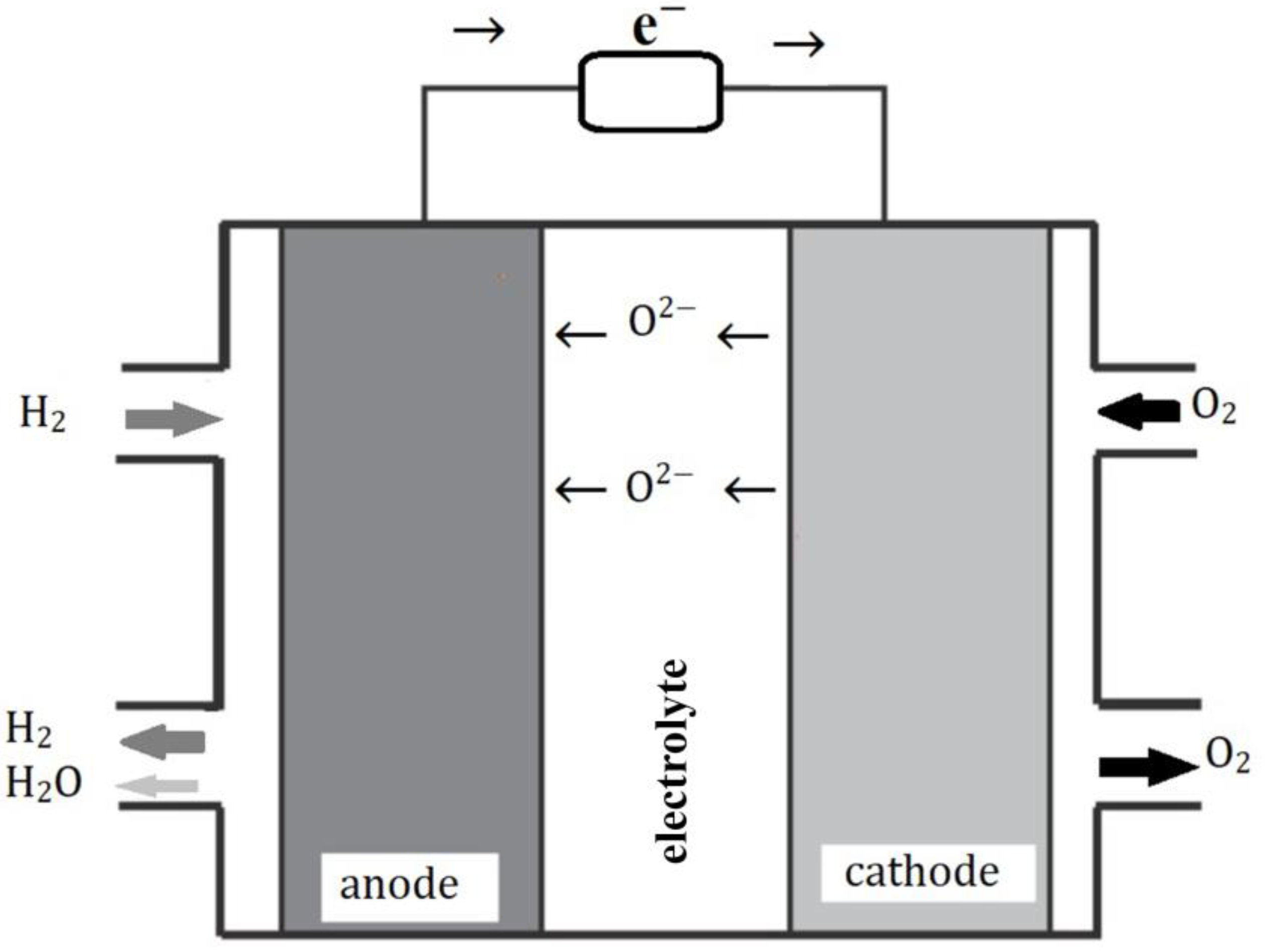
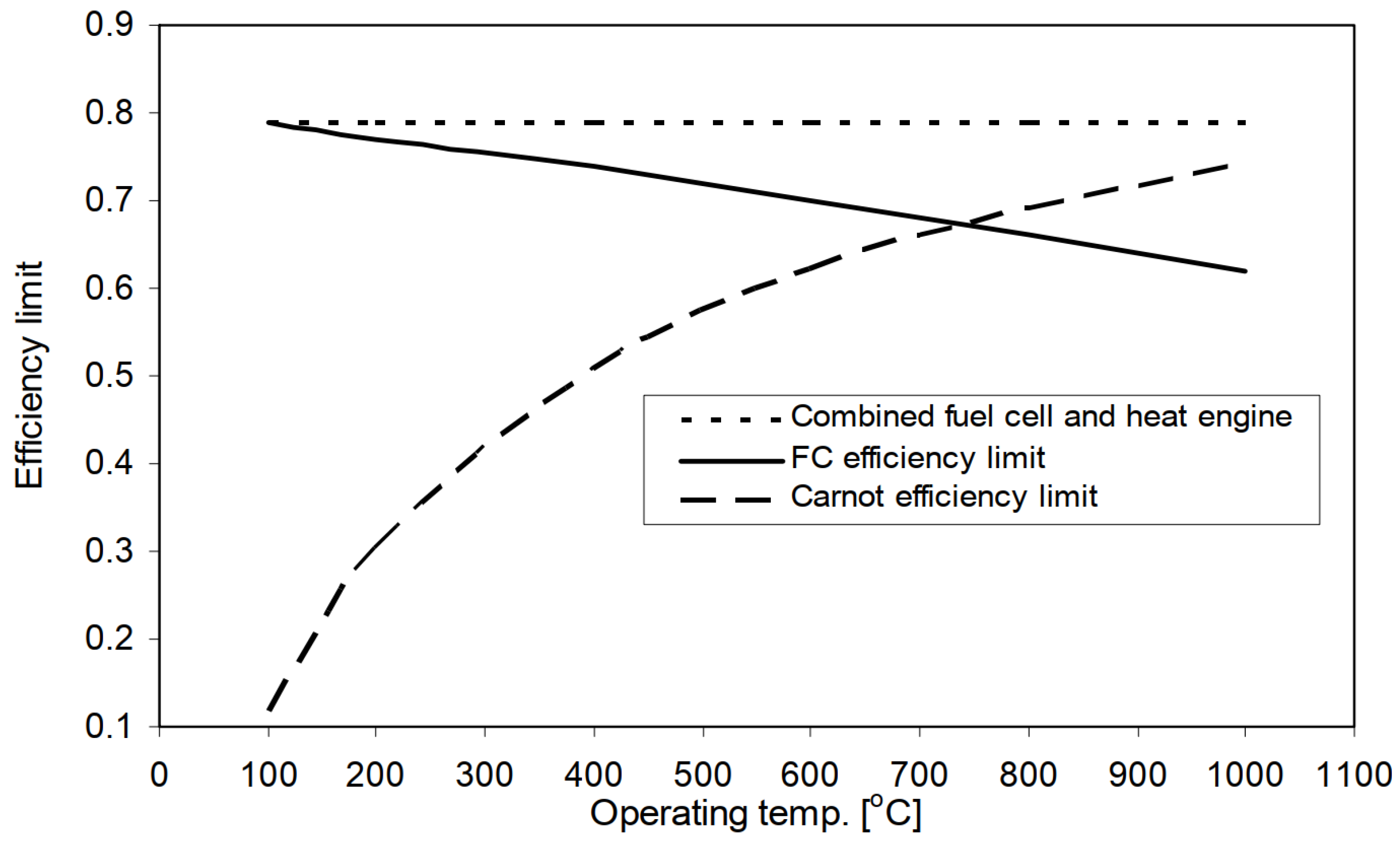
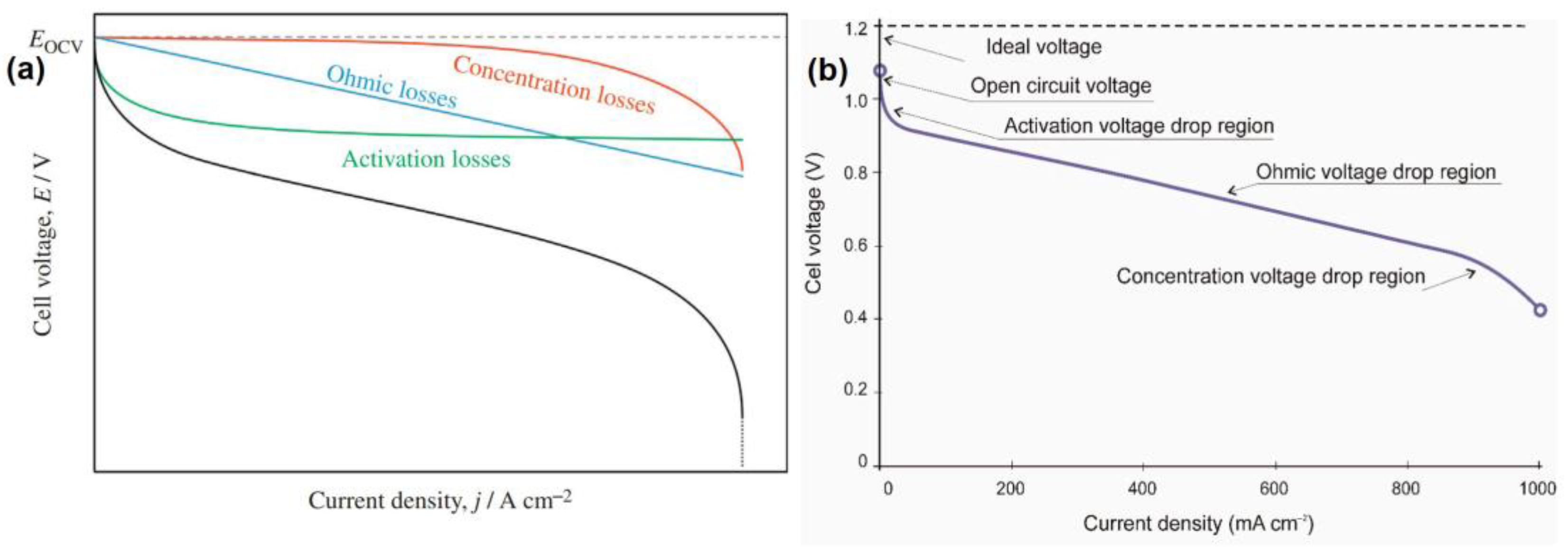
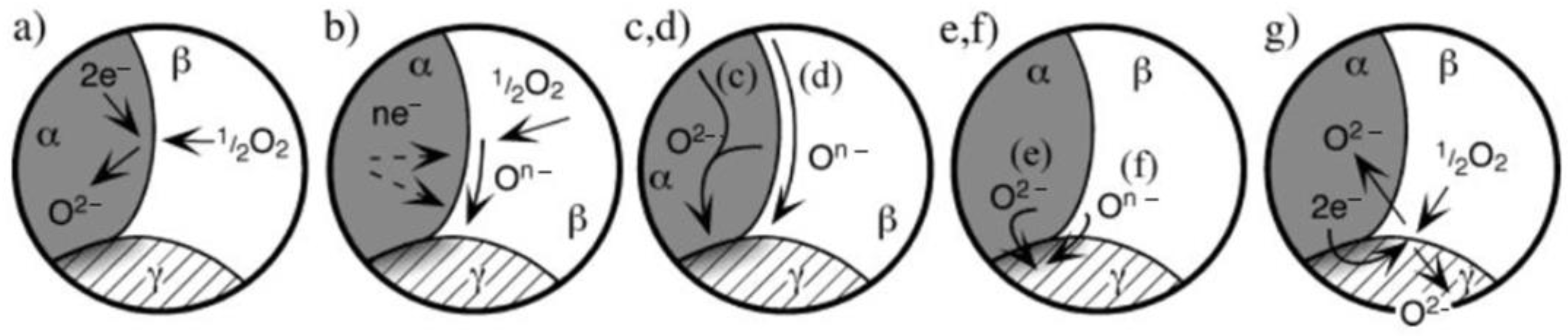
Table 1.
Comparison of fuel cells with other power-generating systems [11].
Table 1.
Comparison of fuel cells with other power-generating systems [11].
| Reciprocating Engine: Diesel | Turbine Generator | Photovoltaic | Wind Turbine | Fuel Cells | |
|---|---|---|---|---|---|
| Power range | 500 kW to 50 MW | 500 kW to 5 MW | 1 kW to 1 MW | 10 kW to 1 MW | 200 kW to 2 MW |
| Efficiency | 35% | 29–42% | 6–19% | 25% | 40–85% |
| Capital cost (USD/kW) | 200–350 | 450–870 | 6600 | 1000 | 1500–3000 |
| Operation and Maintenance cost (USD/kW) | 0.005–0.015 | 0.005–0.0065 | 0.001–0.004 | 0.01 | 0.0019–0.0153 |
Table 2.
Comparison of different types of fuel cells [6].
Table 2.
Comparison of different types of fuel cells [6].
| Fuel Cell | Operating Temperature (°C) | Power (kW) | Efficiency (%) | Application |
|---|---|---|---|---|
| PEM | 60–110 | 0.01–250 | 40–55% | Portable, mobile, and low power generation |
| AFC | 70–130 | 0.1–50 | 50–70% | Mobile, space, and military |
| PAFC | 175–210 | 50–1000 | 40–45% | Mobile to large-scale power generation and CHP |
| MCFC | 550–650 | 200–100,000 | 50–60% | Large-scale power generation |
| SOFC | 500–1000 | 0.5–2000 | 40–72% | Vehicle auxiliary power units, medium- to large-scale power generation and CHP, off-grid power, and micro-CHP |
| DMFC | 70–130 | 0.001–100 | 40% | Mobile and portable |
Table 3.
Advantages and disadvantages of the main coating processes in the fabrication of SOFCs.
| Fabrication Technique | Advantages | Disadvantages |
|---|---|---|
| CVD |
|
|
| PVD |
|
|
| ALD |
|
|
| AD |
|
|
| Dip coating |
|
|
| Spin coating |
|
|
| Screen Printing |
|
|
| Tape casting |
|
|
Disclaimer/Publisher’s Note: The statements, opinions and data contained in all publications are solely those of the individual author(s) and contributor(s) and not of MDPI and/or the editor(s). MDPI and/or the editor(s) disclaim responsibility for any injury to people or property resulting from any ideas, methods, instructions or products referred to in the content. |
© 2023 by the authors. Licensee MDPI, Basel, Switzerland. This article is an open access article distributed under the terms and conditions of the Creative Commons Attribution (CC BY) license (https://creativecommons.org/licenses/by/4.0/).
Share and Cite
MDPI and ACS Style
Choolaei, M.; Vostakola, M.F.; Horri, B.A. Recent Advances and Challenges in Thin-Film Fabrication Techniques for Low-Temperature Solid Oxide Fuel Cells. Crystals 2023, 13, 1008. https://doi.org/10.3390/cryst13071008
AMA Style
Choolaei M, Vostakola MF, Horri BA. Recent Advances and Challenges in Thin-Film Fabrication Techniques for Low-Temperature Solid Oxide Fuel Cells. Crystals. 2023; 13(7):1008. https://doi.org/10.3390/cryst13071008
Chicago/Turabian StyleChoolaei, Mohammadmehdi, Mohsen Fallah Vostakola, and Bahman Amini Horri. 2023. "Recent Advances and Challenges in Thin-Film Fabrication Techniques for Low-Temperature Solid Oxide Fuel Cells" Crystals 13, no. 7: 1008. https://doi.org/10.3390/cryst13071008
Note that from the first issue of 2016, this journal uses article numbers instead of page numbers. See further details here.