


Structure–Property Correlation between Friction-Welded Work Hardenable Al-4.9Mg Alloy Joints
by
 , ,
, ,
Aditya M. Mahajan
1,
K. Vamsi Krishna
1,
M. J. Quamar
1,
Ateekh Ur Rehman
2,
Bharath Bandi
3 and
N. Kishore Babu
1,* 1
Department of Metallurgical and Materials Engineering, National Institute of Technology Warangal, Warangal 506004, India
2
Department of Industrial Engineering, College of Engineering, King Saud University, Riyadh 11451, Saudi Arabia
3
Warwick Manufacturing Group (WMG), University of Warwick, Coventry CV4 7AL, UK
*
Author to whom correspondence should be addressed.
Crystals 2023, 13(7), 1119; https://doi.org/10.3390/cryst13071119
Submission received: 20 June 2023
/
Revised: 11 July 2023
/
Accepted: 14 July 2023
/
Published: 18 July 2023
(This article belongs to the Special Issue Welding and Joining of Metallic Materials: Microstructure and Mechanical Properties)
Abstract
:Friction welding of aluminum alloys holds immense potential for replacing riveted joints in the structural sections of the aeronautical and automotive sectors. This research aims to investigate the effects on the microstructural and mechanical properties when AA5083 H116 joints are subjected to rotary friction welding. To evaluate the quality of the welds, optical and scanning electron microanalysis techniques were utilized, revealing the formation of sound welds without porosity. The microstructural examination revealed distinct weld zones within the weldment, including the dynamically recrystallized zone (DRZ), thermo-mechanically affected zone (TMAZ), heat-affected zone (HAZ), and base metal (BM). During the friction-welding process, grain refinement occurred, leading to the development of fine equiaxed grains in the DRZ/weld zone. Tensile testing revealed that the weldment exhibited higher strength (YS: 301 ± 6 MPa; UTS: 425 ± 7 MPa) in the BM region compared to the base metal (YS: 207 ± 5 MPa; UTS: 385 ± 9 MPa). However, the weldment demonstrated slightly lower elongation (%El: 13 ± 2) compared to the base metal (%El: 15 ± 3). The decrease in ductility observed in the weldment can be attributed to the presence of distinct weld zones within the welded sample. Also, the tensile graph of the BM showed serrations throughout the curve, which is a characteristic phenomenon known as the Portevin–Le Chatelier effect (serrated yielding) in Al-Mg alloys. This effect occurs due to the influence of dynamic strain aging on the material’s macroscopic plastic deformation. Fractography analysis showcased a wide range of dimple sizes, indicating a ductile fracture mode in the weldment. These findings contribute to understanding the microstructural and mechanical behavior of AA5083 H116 joints subjected to rotary friction welding.
1. Introduction
Aluminum is a versatile metal bearing excellent properties, such as low density, high thermal and electrical conductivity, along with high strength-to-weight ratios. These properties make it an ideal choice for the aerospace, automotive, and shipping industries. Nonetheless, these properties are enhanced or altered by the effect of various alloying elements based on the specified application [1]. The 5xxx series is one such alloy, with magnesium as the primary alloying element. These alloys are considered to be among the strongest of all non-heat-treatable aluminum alloys, and this strength is attained through cold working [2]. The temper designation “H116” in alloys belonging to the 5xxx series signifies that the material has undergone a distinctive blend of cold working and thermal treatment processes. This treatment imparts exceptional resistance to corrosion caused by water and high-humidity conditions. Furthermore, it minimizes the potential impact of stress-corrosion sensitization resulting from exposure to high temperatures [3]. In alloys like AA5059, AA5086, and AA5083, these properties impart excellent weldability, corrosion resistance, and a high strength-to-weight ratio, making them ideal for building shipbuilding and vehicle bodies [4]. Due to these excellent properties and wide range of applications, it becomes essential to join these metals.
Conventionally, these alloys are joined using different fusion-welding techniques, such as metal inert gas (MIG) welding, tungsten inert gas (TIG) welding, etc. However, these joining techniques often result in the formation of various welding defects, such as porosity, distortion, and hot cracking [5]. Samiuddin et al. [6] studied the microstructural and mechanical properties of TIG welded Al-5083 butt joints. They observed that porosity and solidification cracking were the most common defects, resulting in an 18.26% loss of base metal strength after welding. Porosity is caused by the entrapment of hydrogen gas during the solidification process, as hydrogen is highly soluble in molten aluminium, leading to the formation of bubble-like nucleation [7]. Another frequent defect observed in the joining of these alloys is the degradation of the heat-affected zone (HAZ), which is more common in commercial alloys due to the higher weight percentage of alloying elements [8]. As mentioned, cold working is the major strengthening mechanism in 5xxx series alloys and is negatively affected by fusion welding. Cetinel et al. [9] investigated the weldment of AA5083 and AA6061 joined through TIG welding. They observed a significant loss of cold work after welding, resulting in the degradation of strength and hardness. Some reports suggest that the evaporation of volatile elements at high temperatures and the formation of columnar grains during solidification are the main causes of strength loss and weld metal degradation during TIG welding [10,11]. Furthermore, welding defects like solidification cracking in these alloys are highly influenced by the weld metal composition [12]. The composition of the welding metal is influenced by both the filler metal used and the extent of dilution that occurs during welding at elevated temperatures. Therefore, it is essential to select the correct filler metal as it can adulterate the homogeneity of the base metal.
Solid-state welding is one of the more advantageous joining methods for aluminum alloys, as it avoids melting and the defects caused during these processes, such as porosity and solidification cracking. Rotary friction welding (RFW) is a versatile solid-state welding technique currently being used as a promising method for welding aluminum alloys. The principal operation of the rotary friction-welding technique can be divided into three major steps: (i) Softening of the material caused by the frictional heat generated due to the movement between the fraying surfaces, (ii) intermixing of the material or plastic deformation, and (iii) forging of the hot metal [13]. These welding techniques overcome flaws such as the loss of volatile alloying elements and distortion, thereby providing a high-quality joint [14]. Pouraliakbar et al. [15] studied the dynamic and softening phenomena of the Al-6Mg alloy during the two-step deformation through the hot compression test. They reported that the softening of the material can be influenced by strain rate. Lienert et al. [16] successfully joined SiC-reinforced 8009 aluminum by inertia friction welding with a minor loss in tensile and hardness properties. Kimura et al. [17] conducted a study to investigate how different friction welding conditions impact the mechanical properties of friction-welded joints in the AA5052 aluminum alloy. The optimum friction speed was found to be 27.5 s−1, and an excellent joint with approximately 93% joint efficiency was observed. This phenomenon was attributed to the mild softening occurring in the peripheral region of the weld, as well as the distinct anisotropic properties observed between the longitudinal and radial directions of the base metal. Elumalai et al. [18] optimized the welding parameters for AA7068 weldment joined by rotary friction welding, and they found that friction (rotational) speed had the highest effect on welding strength. Beygi et al. [19] reviewed the influence of alloying elements on intermetallic formation during friction stir welding (FSW) of aluminum to steel (dissimilar metal joining). They stated that Fe-Al forms different intermetallic compounds (IMCs) such as Fe2Al5 and FeAl3 at the weld interface, whereas Si in the alloy will give solid-solution strengthening and some alloying elements like Ni and Cr in steels retard the diffusion of IMC’s and acts as grain refiners. Sahin et al. [20] examined the microstructural and mechanical properties of near-nanostructured Al 5083 alloys that were subjected to rotary friction welding, which resulted in improved tensile and fatigue strength of the welded samples. However, the significant increase in hardness and mechanical properties was due to the refinement in grain size. Similarly, Pouraliakbar et al. [21] studied the impact of rotation speed (400–1600 rpm), dwell-time (3–60 s), and cooling media (air and water) on microstructural modification (crystalline size) in stir zone (SZ) while performing friction stir spot processing (FSSP) on Al-Cu-Mg alloy. They reported that the weld cooled underwater inhibited more grain growth compared to cooling taking place in the air.
Based on the author’s current understanding, minimal research has been conducted on rotary friction-welded aluminum (5xxx series) alloys. The purpose of this study is to explore the alterations in the microstructure that arise during the rotary friction welding of AA5083 H116 aluminum alloys. Furthermore, the research involves examining different weld zones and analyzing several mechanical properties, including hardness, tensile strength, and fracture analysis of the weldments. Also, the H116 temper condition enhances the alloy’s corrosion resistance, making it useful in a broad range of industries, including shipbuilding. The findings and insights gained from this research endeavor will contribute to the existing knowledge base and provide valuable information for future advancements in the field.
2. Experimental Materials and Methods
2.1. Parent Metal
The parent metals used for rotary friction welding were AA5083 H116 (work hardened) aluminum alloy rods with a length of 100 mm and a diameter of 20 mm. To ensure perpendicularity, these samples were face-turned. The chemical composition details of the base metal sample, AA5083 H116, are provided in Table 1.
2.2. Welding Details
A continuous drive rotary friction welding machine (ETA Technology in Bangalore, India) with a capacity of 100 KN was employed for the welding process [22]. A manually operated personal computer-controlled system displayed the welding data, such as friction pressure and rotational speed. The base metal rods (AA5083 H116) were secured in the respective chucks. As the spindle began rotating at a predetermined speed, the specimens were brought into contact with an initial force (friction pressure). The relative motion or interaction between the specimens resulted in the generation of frictional heat at the contacting region. The combination of frictional heat and a rotary mechanical force led to severe plastic deformation (flash). A sudden pressure (forging pressure) was applied to complete the rotary friction-welding process. The flash was expelled, carrying away the major impurities. The presence of flash on both sides of the weldment indicates that the heat generated during welding was sufficient to produce a sound weld [23].
Several trials were conducted to optimize the welding parameters, such as rotational speed, burn-off length, upset force, and other friction-welding parameters. The ranges of parameters for the welding trials were selected based on the literature. Due to the limited availability of raw materials, only a limited number of experiments could be carried out. Rotational speed, burn-off length, and upset force were varied one parameter at a time to achieve the best welding. The rotational speed was explored in the range of 1200–1400 rpm [24]. A rotational speed of 1400 rpm was finalized, as speeds below 1400 rpm took considerably longer time at the friction stage, and unusual cracks were observed in the flash, indicating insufficient heat generation for complete plastic deformation. Further tests were conducted while maintaining a constant speed of 1400 rpm and varying the friction burn-off in 1 mm increments. The most appropriate flash was observed at 5 mm, beyond which there was no significant advantage except for material wastage. Once these two parameters were set, the best joint was observed at an upset force of 24 kN. Methods such as visual inspection and drop tests were employed to optimize the welding parameters. The welding parameters used for the final welding are displayed in Table 2.
2.3. Metallographic Examination
To section the welded specimens along the cross-section, wire-cut electrical discharge machining (EDM) was employed. Subsequently, they were cold-mounted to ensure straight alignment. The mechanical polishing of the samples was performed using SiC papers ranging from 600 to 200 grit, followed by fine cloth polishing using 3 to 0.5 μm diamond paste. For etching the samples, Keller’s reagent (consisting of 1.5 mL HCl, 1 mL HF, 2.5 mL HNO3, and 95 mL H2O) was utilized for approximately 15–20 s. Microstructural analysis was carried out utilizing an optical microscope and a TESCAN scanning electron microscope (SEM) (Model: VEGA 3 LMU, Brno, Czech Republic). The examination was carried out at an accelerating voltage of 20 KV and a working distance of 9.97 mm. Elemental analysis across the weldment was performed using energy-dispersive X-ray spectroscopy (EDS). The X-ray diffractometer (PANalytical, Malvern, UK) was employed for XRD analysis of the weldment. The X-ray diffractor was configured with a scan current of 30 mA, a step size of 0.01 degrees, and a wavelength of 1.547 Å. A continuous scan mode was used with CuK radiation and incident split detectors. The scan range was specified to be between 5.0 and 90.0 degrees.
2.4. Mechanical Testing
To investigate the mechanical behavior of the AA5083 joints welded using rotary friction welding, several properties, including tensile strength, hardness, and fracture analysis, were examined. The samples were prepared according to ASTM standards. To measure the hardness variation across the weldment, a Vickers micro-indentation device (Shimadzu, HMV 2T E, Kyoto, Japan) was utilized. A load of 50 gm was applied for 15 s on both sides of the weld. The tensile properties of the weldment were assessed using a KAPPA 100 SS-CF universal testing machine from Austria. Tensile tests were conducted at room temperature, employing a crosshead speed of 0.5 mm/min.
3. Results and Discussion
3.1. Base Metal Microstructure
The optical micrographs of the AA5083 base metal alloy are shown in Figure 1. Figure 1a represents the transverse plane (along the cross-section), while Figure 1b represents the longitudinal plane (along the central axis). The microstructure predominantly consists of a heterogeneous mixture of unevenly scattered grains with a segregated microstructure (Figure 1a). Elongated grains can be observed along the longitudinal plane (Figure 1b) of the base metal rods. These pancake-shaped grains result from the rolling operation during manufacturing. Radetic et al. [25] reported that compression along the strain plane leads to this elongation and the formation of lamellar/pancake-shaped grains. They suggested that while these grains are stretched along the rolling direction, they contract equally in the direction perpendicular to it. Solute strengthening, dislocation strengthening, grain refinement, and precipitate hardening are some of the major strengthening mechanisms in non-heat-treatable AA5083 aluminum alloys [26,27]. The presence of point defects generated by the major alloying elements Mn and Mg in AA5083 restricts dislocation motion and enhances material strength at low strain rates. While these alloys derive strength through Mg solute atoms via solute strengthening, an increased Mg content can decrease corrosion resistance [28]. Therefore, work hardening and grain refinement remain the most efficient methods for improving the strength of AA5083 [29]. Figure 2a shows the SEM microstructure of the AA5083 base metal. Furthermore, EDS analysis (Figure 2b) of the base metal microstructure reveals the presence of Mg-rich β (Al3Mg2) precipitates/secondary phases embedded in the α (aluminum) matrix. Many reports suggest the presence of other phases such as Al3Mn2, Al-(Fe, Si, Mn, Cr), Al6Mn, and Mg2Si in this alloy [30].
Figure 3 illustrates the visual view of the rotary friction-welded AA5083 H116 joint. As evident from the figure, sound welds with superior quality are produced, exhibiting an even and uniform flash on both sides of the weldment. This indicates that the heat generated during rotary friction is sufficient for the successful deformation of the base material. Figure 4 displays the macrostructure image of the rotary friction-welded AA5083 H116 joint from a cross-sectional view. It shows a balanced amount of flash on both sides, as well as grain deformation lines across the weld interface. The presence of flash assists in the removal of unwanted oxide layers and other debris, resulting in a clean and seamless weld [5]. These deformation lines are the result of severe plastic deformation that occurs during rotary friction welding [31].
3.2. Microstructure of Weld-Interface
During the rotary friction welding of AA5083 H116, Figure 5 illustrates the various weld zones that form along the weld interface. A detailed microstructural examination conducted across the weld interface revealed the division of the weldment into four distinct zones: (a) dynamically recrystallized zone (DRZ), (b) thermo-mechanically affected zone (TMAZ), (c) heat-affected zone (HAZ), and (d) base metal (BM) [31]. The DRZ exhibited fine (equiaxed) grains, characterized by an average grain size of 5 ± 2 μm, as revealed by microstructural analysis. The refinement of these grains can be attributed to the extreme forces and plastic deformation experienced during rotary friction welding. The continuous rotational movement of the base material promotes the formation of fine recrystallized grains, which significantly influences the final mechanical properties of the weldment [32]. It has been reported that continuous dynamic recrystallization (CDRX) plays a crucial role in the grain refinement mechanism during the friction welding of aluminum alloys [33]. CDRX involves the rearrangement of dislocations to produce subgrains, absorption of dislocations in low-angle grain boundaries, and the eventual formation of high-angle grain boundaries and new dynamically recrystallized grains [34]. It can be observed that the width of the DRZ is reduced towards the center of the weldment, indicating the differential forces experienced during the various stages of friction welding [31]. This phenomenon is observed on either side of the friction weld interface. The TMAZ consists of deformed grains arranged in lines along the direction of flash flow, which provides insight into the direction of deformation. On the other hand, the HAZ exhibits a grain arrangement similar to that of the base metal. Long, elongated grains are observed in the base metal due to deformation during the rolling process. AA5083 being a strain-hardened alloy, these grain shapes are commonly observed, highlighting the alloy’s high-strength properties. However, a slight increase in grain width can be observed in the HAZ, which can be attributed to the high thermal exposure during rotary friction welding.
The EBSD orientation mapping of the friction-welded AA5083 H116 zones is shown in Figure 6, where (a–d) represents the various weld zones formed during rotary friction welding of AA5083 H116, namely DRZ, TMAZ, HAZ, and BM, respectively. It is observed that the BM Al5083 alloy comprises elongated grains parallel to the rolling direction along with equiaxed grains in between the elongated grains as shown in Figure 6d. The average grain size of the equiaxed grains in the BM is 12 ± 3 µm while the larger elongated grains showed an average length of 70 ± 5 μm along the rolling direction. The inverse pole figure (IPF) showed the large portion of BM planes orientated in [101] direction. In contrast, the other zones like DRZ, TMAZ, and HAZ showed the orientation of planes in all directions.
The stir zone comprises fine equiaxed recrystallized grains (DRZ) structure (Figure 6a). The DRZ exhibited the smallest average grain size at the welding center compared to HAZ, TMAZ, and BM. The presence of dynamic recrystallization during the friction welding process accounts for this phenomenon. The DRZ exhibits an average grain size of 5 ± 2 µm. The TMAZ is situated adjacent to the DRZ on both sides, featuring an average grain size of 22 ± 4 µm. TMAZ exhibits a larger grain size when compared to DRZ. This is attributed to lower/partial recrystallization. The grains within the TMAZ exhibit an elongated morphology parallel to the welding interface, which arises from the intense plastic deformation experienced during the frictional stage of welding. Conversely, the HAZ adjacent to the TMAZ displays a coarser grain size of 32 ± 3 µm. As the HAZ is relatively far away from the weld center, it experiences less plastic deformation and heat, which results in the absence of recrystallization. Consequently, the grains formed in the HAZ are coarser compared to those in the TMAZ. Significantly, HAZ exhibits noticeable grain coarsening, which can be attributed to the annealing effect (loss of work hardening) that occurs during the welding process.
Figure 7a,b show the SEM micrograph of the AA5083 H116 friction-welded joint interface and EDS analysis of the weld interface, respectively. The EDS analysis reveals the presence of intermetallic compounds enriched with Fe and Mg. It also demonstrates the uniform intermixing of the main strengthening precipitates, such as β (Al3Mg2), along with various other intermetallic compounds like Al3Mn2 and Al13Fe4 in AA5083 H116. These contribute to the joint’s strength, along with grain refinement during welding. Figure 8a,b show the XRD pattern of the AA5083 H116 base metal and rotary friction-welded AA5083 joint, respectively. The XRD pattern only identifies the Al phase, and the absence of Mg is observed in both conditions (base and weld). This is attributed to the development of the FCC supersaturated solid solution in the Al-Mg alloy, which leads to the diffusion of Mg atoms in the Al lattice [35]. For the welded sample, the scan area is focused on the DRZ/weld zone. The XRD spectra exhibit prominent peaks at 2θ angles of 38.36°, 44.57°, 64.79°, 77.82°, and 81.99°, corresponding to the hkl miller index planes of (111), (200), (220), (311), and (222), respectively. The (111) peak shows the highest peak intensity and texture coefficient, indicating preferred orientation growth.
3.3. Mechanical Properties
Figure 9 illustrates the hardness variation across the weld interface of the rotary friction-welded AA5083 H116 joint. A significant increase in hardness (107 ± 3 HV) can be observed along the DRZ of the weld interface. This can be attributed to grain refinement (recrystallization) that occurs during friction welding, resulting in fine (equiaxed) grains. This grain refinement is a consequence of the severe plastic deformation that takes place during friction welding. Additionally, a noticeable but relatively lower increase in hardness (96 ± 2 HV) can be observed in the TMAZ of the weld interface. This increase is attributed to the partial recrystallization of grains, as sufficient thermal exposure allows for partial recrystallization. The TMAZ exhibits finer grains compared to the HAZ. In the HAZ, grain coarsening and the loss of cold work result in the lowest hardness (82 ± 2 HV) along the weld interface [36]. Furthermore, a hardness of 88 ± 3 HV is observed in the BM region of the weld interface.
Figure 10 depicts a visual view of the failed tensile sample of the rotary friction-welded AA5083 H116 joint. The nature of the fracture is revealed through visual inspection of the fractured sample. Features such as limited necking and a 45° angle along the fracture axis indicate a ductile fracture.
Furthermore, the fracture occurred in the HAZ of the weldment, suggesting that the weld joint interface formed by rotary friction welding possesses superior strength compared to the BM and HAZ. The formation of fine equiaxed grains can be attributed to dynamic recrystallization across the welding interface resulting from severe plastic deformation during friction welding [32]. Reports also indicate a significant loss of work hardening in the HAZ due to thermal exposure during welding, which leads to a reduction in strength [36]. Figure 11 displays the tensile graphs of the rotary friction-welded AA5083 H116 joint and the base metal AA5083 H116. The graph illustrates that rotary friction welding produces a sound weld with superior mechanical properties. The weldment exhibits a YS of 301 ± 6 MPa and a UTS of 425 ± 7 MPa, compared to the BM (YS: 207 ± 5 MPa; UTS: 385 ± 9 MPa). The superior strength of the weldment may be attributed to the formation of fine equiaxed grains in the DRZ. However, the weldment exhibited slightly lower % elongation (%El: 13 ± 2) compared to the BM (%El: 15 ± 3). This reduction in ductility of weldment can be attributed to the formation of various weld zones within the welded sample. The tensile graph of the base metal displays serrations across the curve, which is attributed to a common phenomenon in Al-Mg alloys known as the Portevin–Le Chatelier effect (serrated yielding). This effect is generally caused by the influence of dynamic strain aging on the macroscopic plastic flow of the material. Dislocations moving across the lattice interact with solute atoms, forming a solute atmosphere. The vacancies generated during deformation increase solute mobility in this region, leading to a decrease in dislocation velocity and a locking condition. These locking interactions result in serrations (also known as ‘locking serrations’) where the stress–strain curve experiences rapid spikes in flow stress followed by discontinuous fallbacks [37]. Table 3 presents the tensile properties of the BM and the rotary friction-welded AA5083 H116 joint.
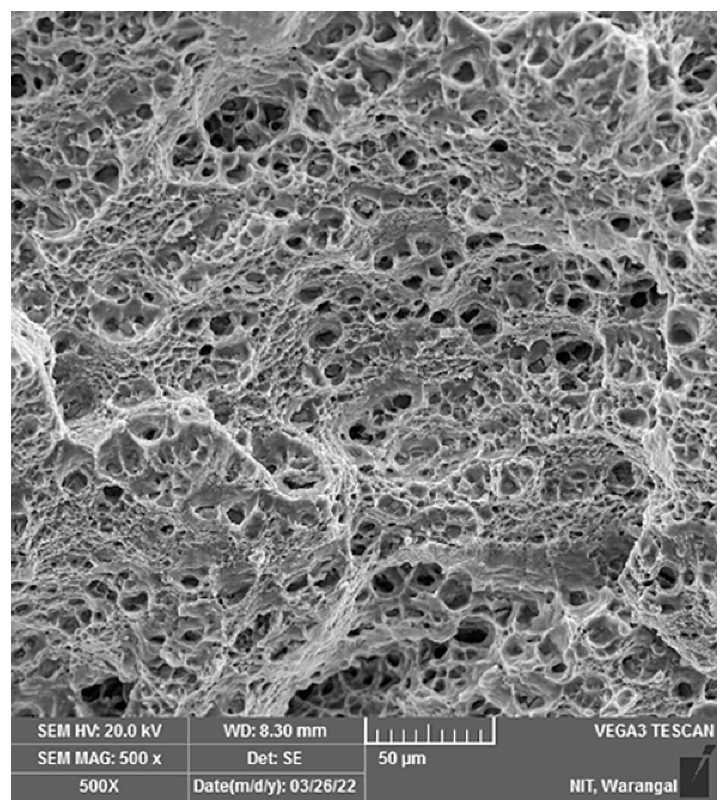
Figure 12 depicts the fractographs of the failed rotary friction-welded AA5083 H116 joint. The fractographs clearly show a dimpled rupture as the mode of failure. The fracture surfaces exhibit features such as dimples, indicating a ductile failure mode. A detailed microscopic investigation of the fracture surfaces reveals subtle changes in overall fracture morphology and intrinsic fracture characteristics. The fractographs also suggest that the majority of the fractured surface is occupied by trans-granular bonding, characterized by the presence of dimples, with some exceptions, such as interfacial bonding resulting from rotary friction welding. The interaction of the base samples during rotary friction welding promotes interface bonding, which is evident from the pattern of large dimples on the fracture surface morphology, thereby enhancing the mechanical properties of the weld.
4. Conclusions
The research on rotary friction welding of AA5083 H116 was successfully presented in this study. The investigation focused on the microstructural and mechanical properties of the weldment, and the following conclusions can be drawn:
- Analysis using optical and electron microscopy revealed the presence of flawless welds of high quality, devoid of any defects such as cracks or porosity.
- Close to the weld interface, two distinct microstructural zones were identified: the dynamically recrystallized zone (DRZ) and the thermomechanically affected zone (TMAZ). The process of rotary friction welding caused significant plastic deformation in the DRZ, resulting in grain refinement. The recrystallized zone exhibited fine equiaxed grains with an average size of 5 ± 2 μm, while the TMAZ was characterized by elongated grains.
- A notable increase in hardness was observed along the recrystallized zone (DRZ) of the weldment. This enhancement can be attributed to the formation of refined grains during the welding process.
- The tensile test specimen failed within the heat-affected zone (HAZ) of the weldment, indicating the superior strength of the weld interface compared to the base metal and HAZ. The weldment demonstrated higher tensile values (YS: 301 ± 6 MPa; UTS: 425 ± 7 MPa) compared to the base metal (YS: 207 ± 5 MPa; UTS: 385 ± 9 MPa). The increased strength of the weldment can be attributed to the presence of fine equiaxed grains in the DRZ.
- The tensile graph of the BM displays serrations across the curve, which is attributed to a common phenomenon in Al-Mg alloys known as the Portevin–Le Chatelier effect (serrated yielding). This effect is generally caused by the influence of dynamic strain aging on the macroscopic plastic flow of the material.
- The weldment exhibited a slightly lower percentage of elongation (%El: 13 ± 2) compared to the base metal (%El: 15 ± 3). This decrease in ductility can be attributed to the formation of distinct weld zones within the welded sample.
Author Contributions
Conceptualization, A.M.M., K.V.K. and M.J.Q.; methodology, A.M.M., K.V.K., B.B., N.K.B., A.U.R. and M.J.Q.; formal analysis, A.M.M., B.B., N.K.B. and A.U.R.; investigation, A.M.M., K.V.K., B.B., N.K.B., A.U.R. and M.J.Q.; resources, A.M.M., K.V.K., B.B., N.K.B., A.U.R. and M.J.Q.; data curation, A.M.M., N.K.B. and A.U.R.; writing—original draft preparation, A.M.M., K.V.K., B.B., N.K.B., A.U.R. and M.J.Q.; writing—review and editing, A.M.M., N.K.B. and A.U.R.; visualization, A.M.M., N.K.B., A.U.R. and M.J.Q.; supervision, N.K.B. and A.U.R.; project administration, N.K.B. and A.U.R.; funding acquisition, A.U.R. All authors have read and agreed to the published version of the manuscript.
Funding
This research was funded by through Researchers Supporting Project number (RSPD2023R701), King Saud University, Riyadh, Saudi Arabia.
Data Availability Statement
Data are contained within this article.
Acknowledgments
The authors are thankful to King Saud University for funding this work through Researchers Supporting Project number (RSPD2023R701), King Saud University, Riyadh, Saudi Arabia.
Conflicts of Interest
The authors declare no conflict of interest.
References
- Mathers, G. The Welding of Aluminum and Its Alloys; Woodhead Publishing Ltd.: Cambridge, UK, 2002. [Google Scholar]
- Wahid, M.A.; Siddiquee, A.N.; Khan, Z.A. Aluminum Alloys in Marine Construction: Characteristics, Application, and Problems from a Fabrication Viewpoint. Mar. Syst. Ocean Technol. 2020, 15, 70–80. [Google Scholar] [CrossRef]
- Kaufman, J.G. Introduction to Aluminium Alloy Tempers; ASM International: Materials Park, OH, USA, 2000. [Google Scholar]
- Sielski, R.A. Research Needs in Aluminum Structure. Ships Offshore Struct. 2008, 3, 57–65. [Google Scholar] [CrossRef]
- Olson, D.L.; Siewert, T.A.; Liu, S.; Edwards, G.R. Welding, Brazing, and Soldering; ASM International: Materials Park, OH, USA, 1993. [Google Scholar]
- Samiuddin, M.; Li, J.; Taimoor, M.; Siddiqui, M.N.; Siddiqui, S.U.; Xiong, J. Investigation on the Process Parameters of TIG-Welded Aluminum Alloy through Mechanical and Microstructural Characterization. Defence Technol. 2021, 17, 1234–1248. [Google Scholar] [CrossRef]
- Praveen, P.; Yarlagadda, P.K.D.V. Meeting Challenges in Welding of Aluminum Alloys through Pulse Gas Metal Arc Welding. J. Mater. Process. Technol. 2005, 164–165, 1106–1112. [Google Scholar] [CrossRef]
- Torok, I.; Juhasz, K.; Meilinger, A.; Balogh, A. Main Characteristics of Fusion and Pressure Welding of Aluminium Alloys. Metals 2012, 2, 91. [Google Scholar]
- Cetinel, H.; Ayvaz, M. Microstructure and Mechanical Properties of AA 5083 and AA 6061 Welds Joined with AlSi5 and AlSi12 Wires. Mater. Test. 2014, 56, 884–890. [Google Scholar] [CrossRef]
- Babu, N.K.; Talari, M.K.; Pan, D.; Sun, Z.; Wei, J.; Sivaprasad, K. Microstructural Characterization and Grain Refinement of AA6082 Gas Tungsten Arc Welds by Scandium Modified Fillers. Mater. Chem. Phys. 2012, 137, 543–551. [Google Scholar] [CrossRef]
- Banerjee, K.; Militzer, M.; Perez, M.; Wang, X. Nonisothermal Austenite Grain Growth Kinetics in a Microalloyed X80 Linepipe Steel. Metall. Mater. Trans. A 2010, 41, 3161–3172. [Google Scholar] [CrossRef]
- Koilraj, M.; Sundareswaran, V.; Vijayan, S.; Koteswara Rao, S.R. Friction Stir Welding of Dissimilar Aluminum Alloys AA2219 to AA5083—Optimization of Process Parameters Using Taguchi Technique. Mater. Des. 2012, 42, 1–7. [Google Scholar] [CrossRef]
- Thomas, M.; Nicholas, E.D.; Needham, J.C.; Murch, M.G.; Temple Smith, P.; Dawes, C. International Patent Application No. PCT/GB92/02203 and GB Patent Application No. 9125978.8; Weld Institute (TWI): Cambridge, UK, 1991. [Google Scholar]
- Nicholas, E.D. Developments in the Friction Stir Welding of Metals. Materials 2019, 12, 139. [Google Scholar]
- Pouraliakbar, H.; Pakbaz, M.; Firooz, S.; Jandaghi, M.R.; Khalaj, G. Study on the dynamic and static softening phenomena in Al–6Mg alloy during two-stage deformation through interrupted hot compression test. Measurement 2016, 77, 50. [Google Scholar] [CrossRef]
- Lienert, T.J.; Baeslack, W.A.; Ringnalda, J.; Fraser, H.L. Inertia-Friction Welding of SiC-Reinforced 8009 Aluminium. J. Mater. Sci. 1996, 31, 2149–2157. [Google Scholar] [CrossRef]
- Kimura, M.; Choji, M.; Kusaka, M.; Seo, K.; Fuji, A. Effect of Friction Welding Conditions on Mechanical Properties of A5052 Aluminium Alloy Friction Welded Joint. Sci. Technol. Weld. Join. 2006, 11, 209–215. [Google Scholar] [CrossRef]
- Elumalai, B.; Omsakthivel, U.; Yuvaraj, G.; Giridharan, K.; Vijayanand, M.S. Optimization of Friction Welding Parameters on Aluminium 7068 Alloy. Mater. Today Proc. 2021, 45, 1919–1923. [Google Scholar] [CrossRef]
- Beygi, R.; Galvao, I.; Akhavan-Safar, A.; Pouraliakbar, H.; Fallah, V.; da Silva, L.F. Effect of Alloying Elements on Intermetallic Formation during Friction Stir Welding of Dissimilar Metals: A Critical Review on Aluminum/Steel. Metals 2023, 13, 768. [Google Scholar] [CrossRef]
- Sahin, M.; Balasubramanian, N.; Misirli, C.; Akata, H.E.; Can, Y.; Ozel, K. On Properties at Interfaces of Friction Welded Near-Nanostructured Al 5083 Alloys. Int. J. Adv. Manuf. Technol. 2012, 61, 935–943. [Google Scholar] [CrossRef]
- Pouraliakbar, H.; Beygi, R.; Fallah, V.; Monazzah, A.H.; Jandaghi, M.R.; Khalaj, G.; da Silva, L.F.; Pavese, M. Processing of Al-Cu-Mg alloy by FSSP: Parametric analysis and the effect of cooling environment on microstructure evolution. Mater. Lett. 2022, 308, 131157. [Google Scholar] [CrossRef]
- Masaaki, K.; Masahiro, K.; Koichi, K. Effect of Friction Welding Conditions on Joint Properties of Austenitic Stainless Steel Joints by Friction Stud Welding. Weld. Int. 2018, 32, 274–288. [Google Scholar] [CrossRef]
- Shete, N.; Deokar, S.U. A Review Paper on Rotary Friction Welding. IOP Conf. Ser. Mater. Sci. Eng. 2017, 5, 1557. [Google Scholar]
- Sasmito, A.; Ilman, M.N.; Iswanto, P.T.; Muslih, R. Effect of Rotational Speed on Static and Fatigue Properties of Rotary Friction Welded Dissimilar AA7075/AA5083 Aluminium Alloy Joints. Metals 2022, 12, 99. [Google Scholar] [CrossRef]
- Radetić, T.; Popović, M.; Romhanji, E.; Milović, B.; Dodok, R. Microstructure Evolution of the Hot-Rolled Modified AA 5083 Alloys during the Two-Stage Thermal Treatment. In Proceedings of the 4th International Conference Processing and Structure of Materials, Palic, Serbia, 27–29 May 2010. [Google Scholar]
- Huskins, E.L.; Cao, B.; Ramesh, K.T. Strengthening Mechanisms in an Al–Mg Alloy. Mater. Sci. Eng. A 2010, 527, 1292–1298. [Google Scholar] [CrossRef]
- Engler, O.; Miller-Jupp, S. Control of Second-Phase Particles in the Al-Mg-Mn Alloy AA 5083. J. Alloys Compd. 2016, 689, 998–1010. [Google Scholar] [CrossRef]
- Gubicza, J.; Chinh, N.Q.; Horita, Z.; Langdon, T.G. Effect of Mg Addition on Microstructure and Mechanical Properties of Aluminum. Mater. Sci. Eng. A 2004, 387–389, 55–59. [Google Scholar] [CrossRef] [Green Version]
- Krishna, K.S.V.B.R.; Chandra Sekhar, K.; Tejas, R.; Naga Krishna, N.; Sivaprasad, K.; Narayanasamy, R.; Venkateswarlu, K. Effect of Cryorolling on the Mechanical Properties of AA5083 Alloy and the Portevin–Le Chatelier Phenomenon. Mater. Des. 2015, 67, 107–117. [Google Scholar] [CrossRef]
- Yi, G.; Sun, B.; Poplawsky, J.D.; Zhu, Y.; Free, M.L. Investigation of Pre-Existing Particles in Al 5083 Alloys. J. Alloys Compd. 2018, 740, 461–469. [Google Scholar] [CrossRef]
- Li, P.; Wang, S.; Xia, Y.; Hao, X.; Lei, Z.; Dong, H. Inhomogeneous Microstructure and Mechanical Properties of Rotary Friction Welded AA2024 Joints. J. Mater. Res. Technol. 2020, 9, 5749–5760. [Google Scholar] [CrossRef]
- Barcellona, A.; Buffa, G.; Fratini, L. Process Parameters Analysis in Friction Stir Welding of AA6082-T6 Sheets. In Proceedings of the ESAFORM Conference, Brescia, Italy, 28 April 2004. [Google Scholar]
- Buffa, G.; Fratini, L.; Shivpuri, R. CDRX Modelling in Friction Stir Welding of AA7075-T6 Aluminum Alloy: Analytical Approaches. J. Mater. Process. Technol. 2007, 191, 356–359. [Google Scholar] [CrossRef]
- Galiyev, A.; Kaibyshev, R.; Gottstein, G. Correlation of Plastic Deformation and Dynamic Recrystallization in Magnesium Alloy ZK60. Acta Mater. 2001, 49, 1199–1207. [Google Scholar] [CrossRef]
- Wagih, A. Mechanical Properties of Al–Mg/Al2O3 Nanocomposite Powder Produced by Mechanical Alloying. Adv. Powder Technol. 2015, 26, 253–258. [Google Scholar] [CrossRef]
- Palanivel, R.; Koshy Mathews, P.; Murugan, N.; Dinaharan, I. Effect of Tool Rotational Speed and Pin Profile on Microstructure and Tensile Strength of Dissimilar Friction Stir Welded AA5083-H111 and AA6351-T6 Aluminum Alloys. Mater. Des. 2012, 40, 7–16. [Google Scholar] [CrossRef]
- McCormick, P.G. The Portevin-Le Chatelier Effect in an Al-Mg-Si Alloy. Acta Metall. 1971, 19, 463–471. [Google Scholar] [CrossRef]
Figure 1.
The optical microstructure of the AA5083 base metal in (a) transverse plane (along the cross-section) and (b) longitudinal plane (along the central axis).
Figure 1.
The optical microstructure of the AA5083 base metal in (a) transverse plane (along the cross-section) and (b) longitudinal plane (along the central axis).
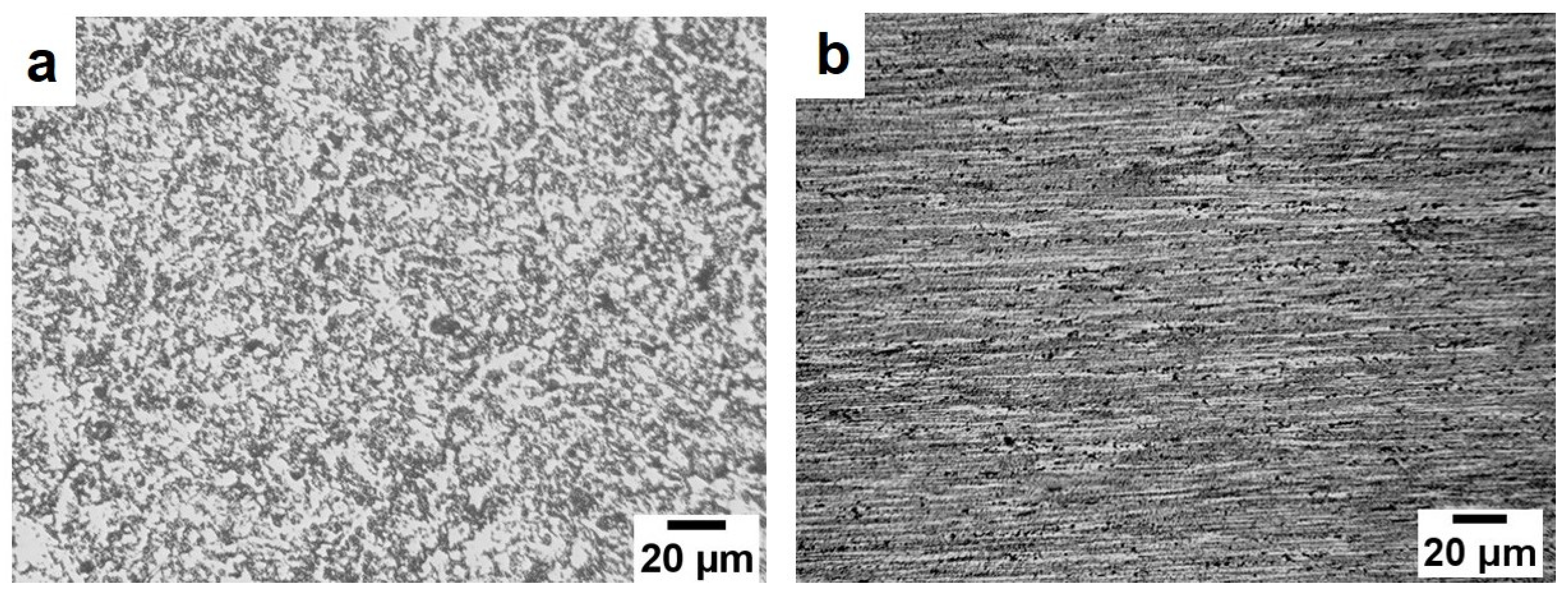
Figure 2.
SEM micrograph of the (a) AA5083 H116 base metal and (b) EDS analysis.
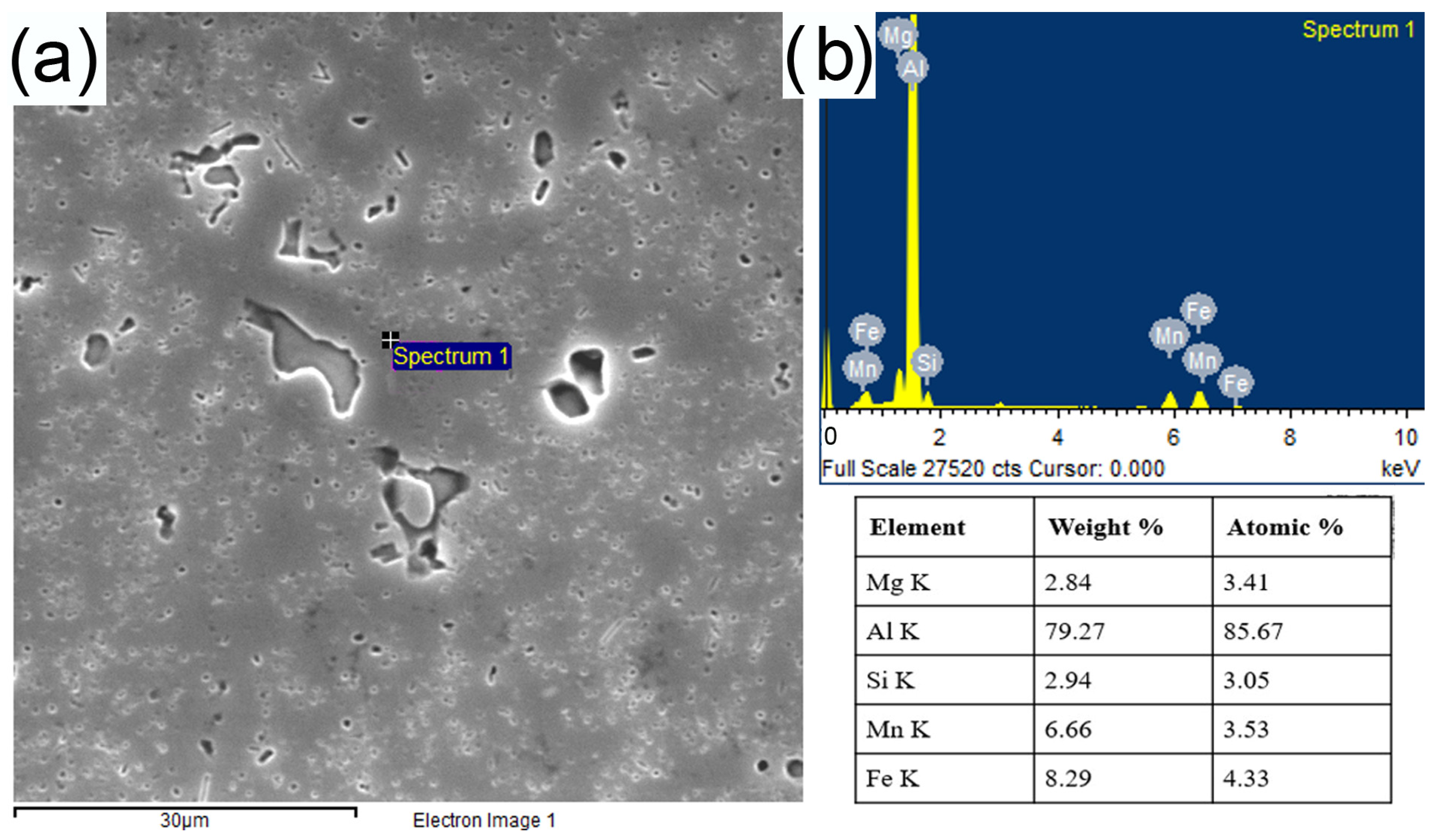
Figure 3.
Visual view of rotary friction-welded AA5083 H116 joint.
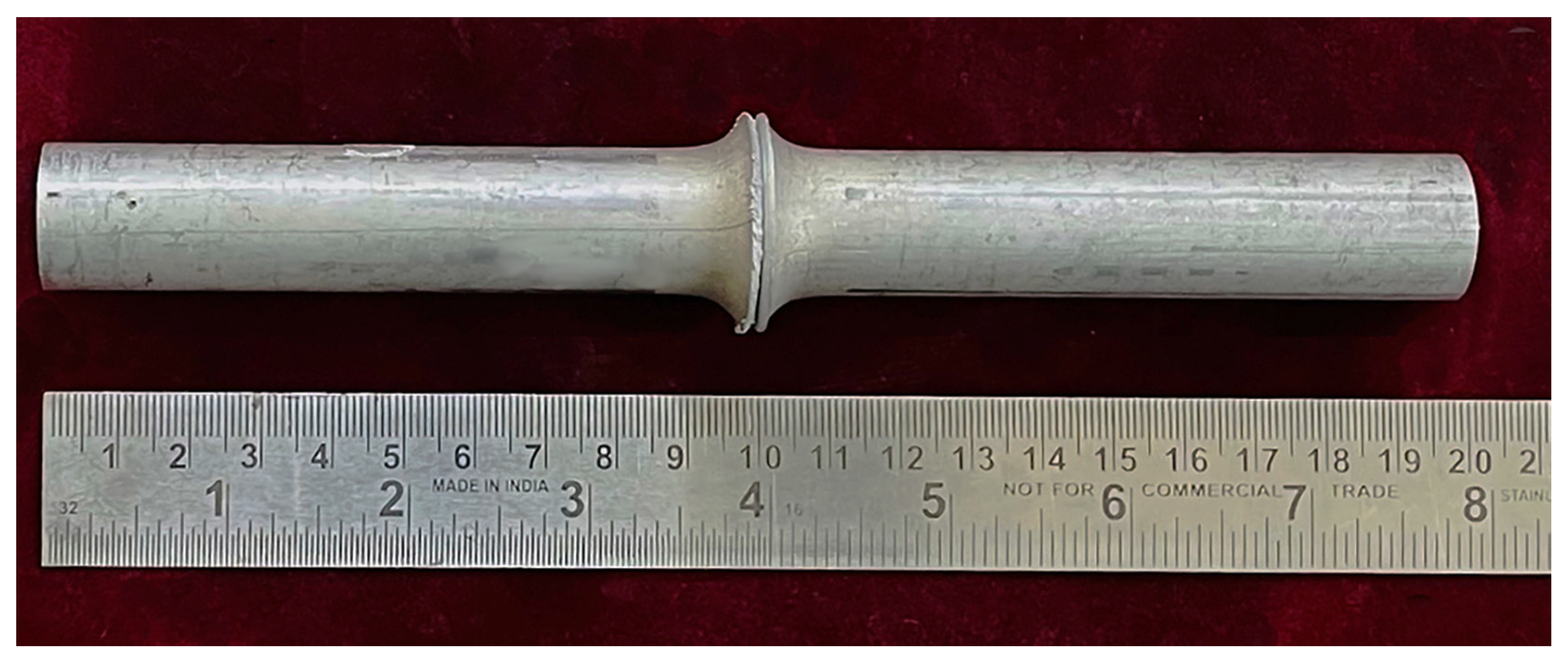
Figure 4.
Macrostructure of rotary friction-welded AA5083 H116 joint.
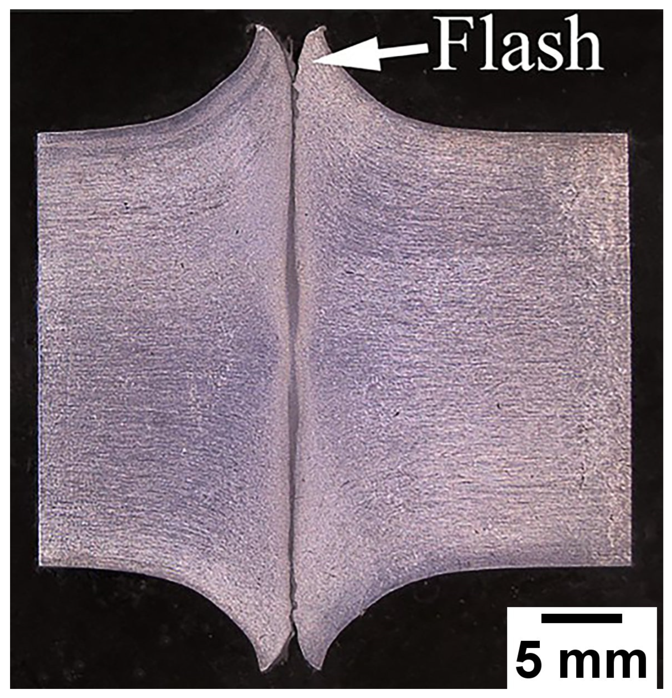
Figure 5.
Microstructure across the various weld zones formed along the weld interface during rotary friction welding of AA5083 H116 joint.
Figure 5.
Microstructure across the various weld zones formed along the weld interface during rotary friction welding of AA5083 H116 joint.
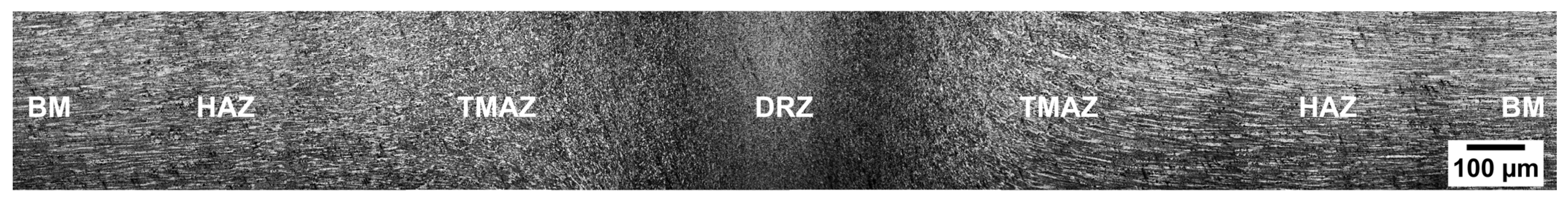
Figure 6.
EBSD orientation mapping of the AA5083 H116 friction-welded samples (a) DRZ, (b) TMAZ, (c) HAZ, and (d) BM.
Figure 6.
EBSD orientation mapping of the AA5083 H116 friction-welded samples (a) DRZ, (b) TMAZ, (c) HAZ, and (d) BM.

Figure 7.
SEM micrograph of the AA5083 H116 friction-welded joint (a) weld interface and (b) EDS analysis of the weld interface.
Figure 7.
SEM micrograph of the AA5083 H116 friction-welded joint (a) weld interface and (b) EDS analysis of the weld interface.

Figure 8.
XRD pattern of the (a) AA5083 H116 base metal and (b) rotary friction-welded AA5083 joint.
Figure 8.
XRD pattern of the (a) AA5083 H116 base metal and (b) rotary friction-welded AA5083 joint.
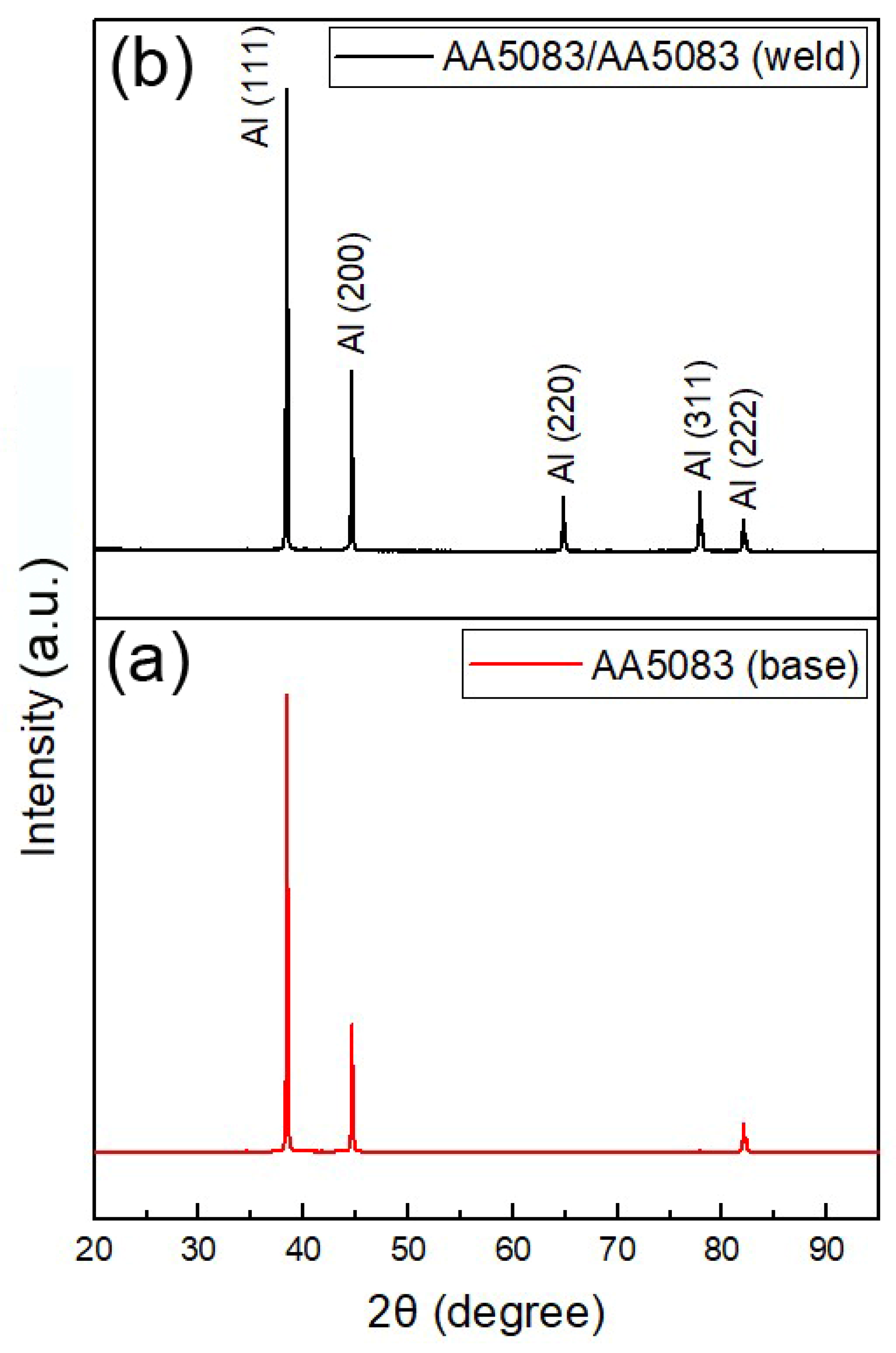
Figure 9.
Microhardness distribution across the weld interface of AA5083 joint.

Figure 10.
Failure location of tensile specimen of AA5083 H116 joint.
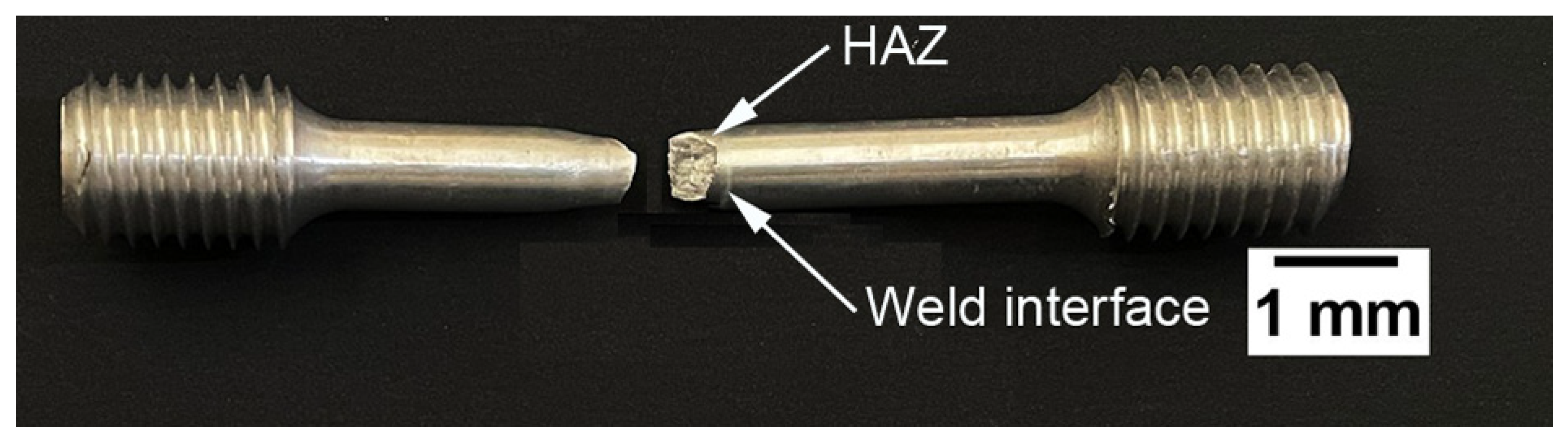
Figure 11.
Typical tensile curves of AA5083 base compared with rotary friction-welded AA5083 H116 joint.
Figure 11.
Typical tensile curves of AA5083 base compared with rotary friction-welded AA5083 H116 joint.

Figure 12.
Fracture surface of rotary friction-welded AA5083 H116 joint.

Table 1.
Chemical composition of AA5083 H116.
| Element | Zn | Mn | Mg | Cu | Cr | Fe | Si | Al |
|---|---|---|---|---|---|---|---|---|
| Wt. % | 0.11 | 0.53 | 4.9 | 0.03 | 0.09 | 0.27 | 0.04 | Bal |
Table 2.
Welding Parameters.
| Parameters | Explored Ranges | Selected Values |
|---|---|---|
| Rotational speed (rev/min) | 1200–1400 | 1400 |
| Friction burn-off (mm) | 2–5 | 5 |
| Upset force (kN) | 19–24 | 24 |
| Soft force (kN) | (Constant) | 2 |
| Soft force time (s) | (Constant) | 4 |
| Friction force (kN) | (Constant) | 12 |
| Upset time (s) | (Constant) | 3 |
Table 3.
Tensile properties of the AA5083 H116 base metal and friction welds made on AA5083 H116 alloy.
Table 3.
Tensile properties of the AA5083 H116 base metal and friction welds made on AA5083 H116 alloy.
| Name | Yield Stress (YS), MPa | Ultimate Tensile Strength (UTS), MPa | % Elongation (El%) |
|---|---|---|---|
| AA5083/AA5083 (weld) | 301 ± 6 | 425 ± 7 | 13 ± 2 |
| AA5083 H116 (base) | 207 ± 5 | 385 ± 9 | 15 ± 3 |
Disclaimer/Publisher’s Note: The statements, opinions and data contained in all publications are solely those of the individual author(s) and contributor(s) and not of MDPI and/or the editor(s). MDPI and/or the editor(s) disclaim responsibility for any injury to people or property resulting from any ideas, methods, instructions or products referred to in the content. |
© 2023 by the authors. Licensee MDPI, Basel, Switzerland. This article is an open access article distributed under the terms and conditions of the Creative Commons Attribution (CC BY) license (https://creativecommons.org/licenses/by/4.0/).
Share and Cite
MDPI and ACS Style
Mahajan, A.M.; Krishna, K.V.; Quamar, M.J.; Rehman, A.U.; Bandi, B.; Babu, N.K. Structure–Property Correlation between Friction-Welded Work Hardenable Al-4.9Mg Alloy Joints. Crystals 2023, 13, 1119. https://doi.org/10.3390/cryst13071119
AMA Style
Mahajan AM, Krishna KV, Quamar MJ, Rehman AU, Bandi B, Babu NK. Structure–Property Correlation between Friction-Welded Work Hardenable Al-4.9Mg Alloy Joints. Crystals. 2023; 13(7):1119. https://doi.org/10.3390/cryst13071119
Chicago/Turabian StyleMahajan, Aditya M., K. Vamsi Krishna, M. J. Quamar, Ateekh Ur Rehman, Bharath Bandi, and N. Kishore Babu. 2023. "Structure–Property Correlation between Friction-Welded Work Hardenable Al-4.9Mg Alloy Joints" Crystals 13, no. 7: 1119. https://doi.org/10.3390/cryst13071119
Note that from the first issue of 2016, this journal uses article numbers instead of page numbers. See further details here.