


Effect of Ultrasonic Rolling on the Organization and Properties of a High-Speed Laser Cladding IN 718 Superalloy Coating

1
School of Mechanical and Electrical Engineering, China University of Mining and Technology, XuZhou 221116, China
2
Jiangsu Key Laboratory of Mine Mechanical and Electrical Equipment, China University of Mining and Technology, XuZhou 221116, China
*
Author to whom correspondence should be addressed.
Crystals 2023, 13(8), 1214; https://doi.org/10.3390/cryst13081214
Submission received: 16 June 2023
/
Revised: 28 July 2023
/
Accepted: 4 August 2023
/
Published: 5 August 2023
(This article belongs to the Special Issue Laser-Induced Surface Modification)
Abstract
:To repair or improve the performance of H13 hot working molds through the additive manufacturing process, IN 718 was coated on H13 die steel by high-speed laser cladding followed by an ultrasonic surface rolling process (USRP). The mechanism of ultrasonic surface rolling on the mechanical properties of the coating was studied. After USRP, the coating exhibited severe plastic deformation; the microscopic organization of the surface layer was refined and the particle size was significantly reduced. The violent plastic deformation of the coating caused by USRP improved the dislocation density and the grain boundary density, providing an improved yield strength of the coating and improving the high-temperature wear resistance of the coating. After USRP, the surface hardness of the coating increased by 30%. Compared with the coating without USRP, the wear resistance of the coating greatly improved; the wear rate was reduced by 51% and the wear mechanism of the coating changed from large-area adhesive wear and severe abrasive wear to small-area adhesive wear and slight abrasive wear. The IN 718 coating after USRP had a higher hardness and greater wear resistance, significantly improving the service life of H13 steel.
1. Introduction
H13 mold steel is widely used in the manufacture of hot working molds and die-casting molds due to its quenching behavior, toughness, and resistance to hot cracking after quenching and tempering. The working environment of H13 steel is severe and is often affected by cold and hot cycles. The surface is mostly affected by thermal wear, high-temperature oxidation, corrosion, and other defects. The failure of H13 steel not only wastes resources, but also leads to an increase in the processing cost [1]. Mold replacements result in a longer processing time and higher costs. Traditional repair methods such as welding waste materials have a low forming quality and high porosity [2].
Additive manufacturing (AM) technology manufactures solid parts by gradually accumulating materials. Compared with traditional material removal technology, AM technology does not require traditional tools and fixtures or multi-channel processing procedures. It can quickly and accurately manufacture parts of any complex shape on a single device which significantly shortens the processing cycle [3]. High-speed laser-cladding technology is a new type of surface modification technology that has emerged in recent years. By changing the intersection position of the laser and powder flow, a cladding layer is formed at an extremely high scanning speed. This results in good-quality forming characteristics with a low dilution, high efficiency, and high bonding strength. Compared with traditional laser-cladding technology, it has the advantages of a high processing efficiency and a high laser utilization rate [4]. The macroscopic properties, microstructure, and corrosion resistance of the coating created using ultra-high-speed laser cladding technology demonstrate its one-of-a-kindness. The distinctive technical qualities of ultra-high speed laser cladding, namely its microstructure characteristics, are attributed to it being more compact, fine, and homogeneous when compared to ordinary laser cladding coating [5]. Li et al. [6] used ultra-high-speed laser cladding and conventional laser cladding to create a thick, defect-free, and metallurgically bonded 431 stainless steel corrosion-resistant coating. The results demonstrate that the microstructure of the ultra-high-speed laser cladding coating is mostly made up of fine dendrites which are finer and more uniform than the microstructure of conventional laser cladding. The Cr content distribution in the ultra-high speed laser cladding coating is more homogeneous within and between dendrites. To improve and repair the surface properties of H13 mold steel, researchers have proposed different additive manufacturing options. Yan et al. [7] prepared 5CrNiMo composite coatings on the surface of H13 steel using high-speed laser cladding; this significantly improved the wear resistance of the substrate. Kou et al. [8] improved the impact toughness and wear resistance of H13 tool steel by refining the microstructure with nanoparticles. Yuan et al. [9] prepared iron-based and cobalt-based fusion cladding layers on H13 steel. The cobalt-based cladding layer increased the wear resistance of the substrate more successfully than the iron-based cladding layer in a comparative analysis.
IN 718 is a type of high-temperature alloy with a comprehensive performance. A yield strength below 650 °C ranks it first in wrought high-temperature alloys. It has good fatigue, radiation, oxidation, and corrosion resistance as well as an effective processing performance and structural stability. It can be used to manufacture various parts with complex shapes and has been widely used in the aerospace, nuclear energy, and petroleum industries [10]. These characteristics ensure that the parts manufactured by IN718 have consistent performance and long service life. By using IN718 as the cladding material, the thermal stability and wear resistance of the substrate (H13 steel) can be increased. The low wear resistance of the alloy limits its application in scenarios with high wear-resistance requirements such as abrasive steel. Despite the fact that numerous researchers have undertaken substantial research on Inconel 718 in recent years, there are still issues that require additional investigation.
As an emerging plastic deformation method, Severe Plastic Deformation (SPD) can introduce large strain during the deformation process so as to effectively refine the metal and obtain a complete large-size bulk sample. By controlling the microstructure during the deformation process, a coating with high strength and large plasticity can be obtained at the same time [11]. The ultrasonic surface rolling process (USRP) is an SPD-based surface modification technique that uses dynamic impact as a rolling force to cause a plastic flow on a metal surface [12]. A machining head composed of a super hard material rolls the metal surface under static extrusion. The mechanical qualities of the surface layer are increased by rolling. As a result, USRP creates a thicker and harder grain surface layer and compresses residual stresses. Compared with conventional cold rolling, USRP produces deeper surface residual compressive stress layers under low-pressure hydrostatic conditions [13].
Ye [14] compared turning and ultrasonic surface rolling to prove that ultrasonic surface rolling could refine the uppermost surface grains and improve the surface characteristics. Auezhan et al. [15] treated the titanium alloy Ti6Al4V using ultrasonic surface rolling. This resulted in a refinement of the grain size from 35.5 μm to 200 nm and a 1.4-fold increase in the surface hardness. Liang et al. [16] observed that the USRP of a TC17 alloy imparted a significant reduction in the surface roughness and a decrease in the surface roughness from 0.5~1.07 μm to 0.04~0.12 μm. The surface morphology and surface roughness were close to those of mechanical-polisher samples, deepening the work-hardening layer and reducing the coefficient of friction.
Although USRP is currently a popular research direction, there are few studies on the effect of ultrasonic rolling on superalloys. The effect of ultrasonic rolling on the high-temperature wear resistance of superalloys has a high research value. In this paper, nickel-based (IN 718) coatings were prepared on the surface of H13 mold steel by high-speed laser cladding. Subsequently, the coating was ultrasonically rolled. The influence of the ultrasonic rolling surface modification mechanism on the microstructure and mechanical properties of the cladding layer was studied to expand the field of use of H13 steel molds. The findings of this study analyze the viability of laser technology and other process combinations to enhance material quality and serve as a reference for strengthening and mending H13 die steel using additive manufacturing technology.
2. Materials and Methods
2.1. Preparation of the Coatings
In this experiment, the cladding layer was prepared using Zhongke Zhongmei ZKZM-6000 high-speed laser-cladding equipment. The performance characteristics are listed in Table 1. The substrate chosen was H13 mold steel with dimensions of 100 mm × 80 mm × 25 mm.
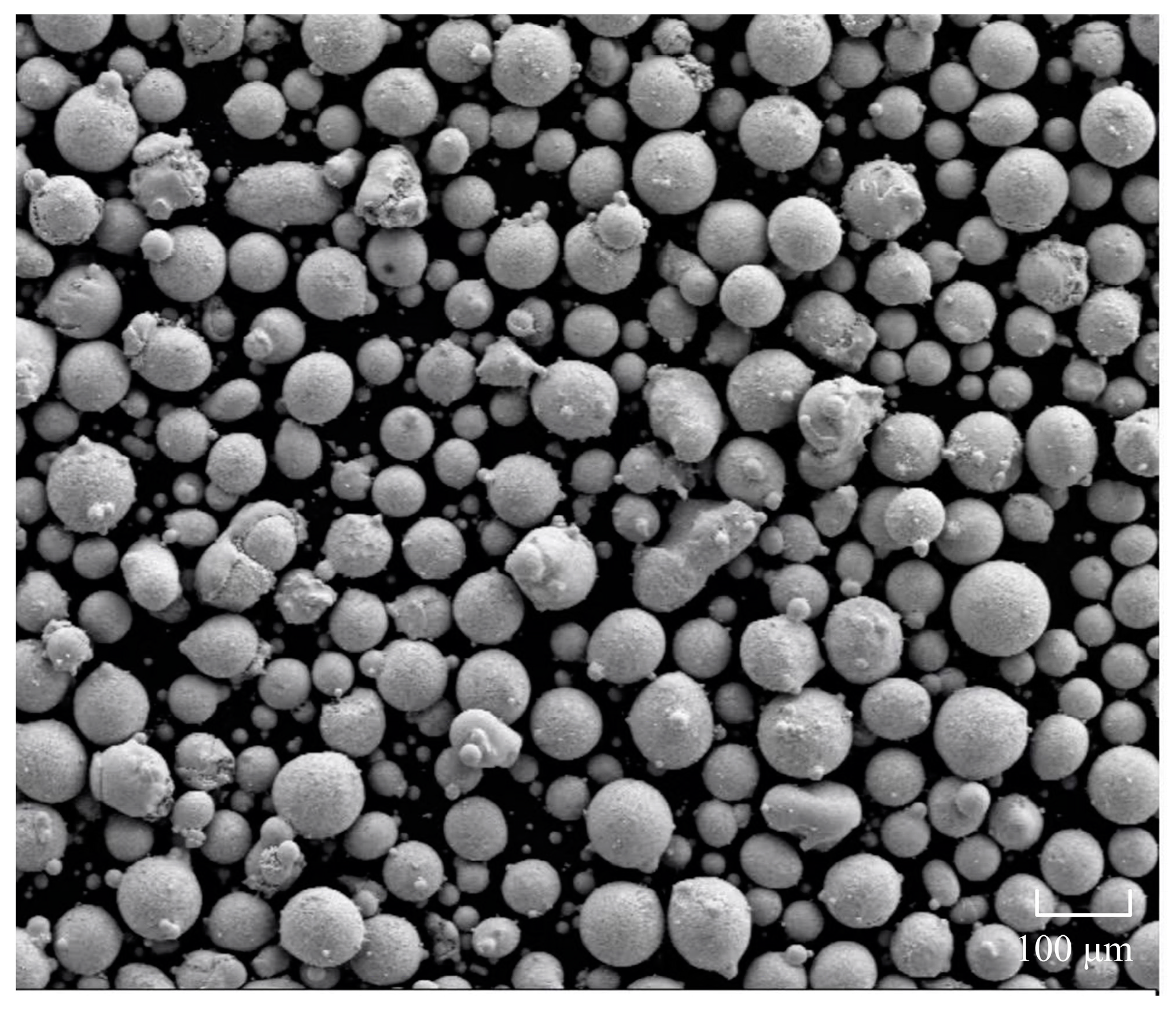
The laser-cladding material was IN 718 self-fluxing alloy powder. The powder was spherical and its size was in the range of 45~105 microns. The powder was produced by the Jiangsu Willari Company. The morphology of the IN 718 powder is shown in Figure 1. Its chemical composition is shown in Table 2. During the laser-cladding process, a coaxial powder supply device was used. With the help of an inert gas flow (argon), the powder supply and the protection of the melted areas were ensured. The powder supply flow rate was 18 L/min. The values of the cladding process parameters were a laser power of 2500 W, a scanning speed of 3000 mm/min, and a feed speed of 20 g/min. A continuous laser was used in the process of laser cladding. Our choice of laser cladding parameters is based on previous research on laser cladding nickel-based alloys [17].
All the samples were milled after cladding. The thickness of the cladding layer before milling was 1.5 mm, the milling thickness was 0.3 mm, the milling speed was 80 m/min, and the milling width was 15 mm.
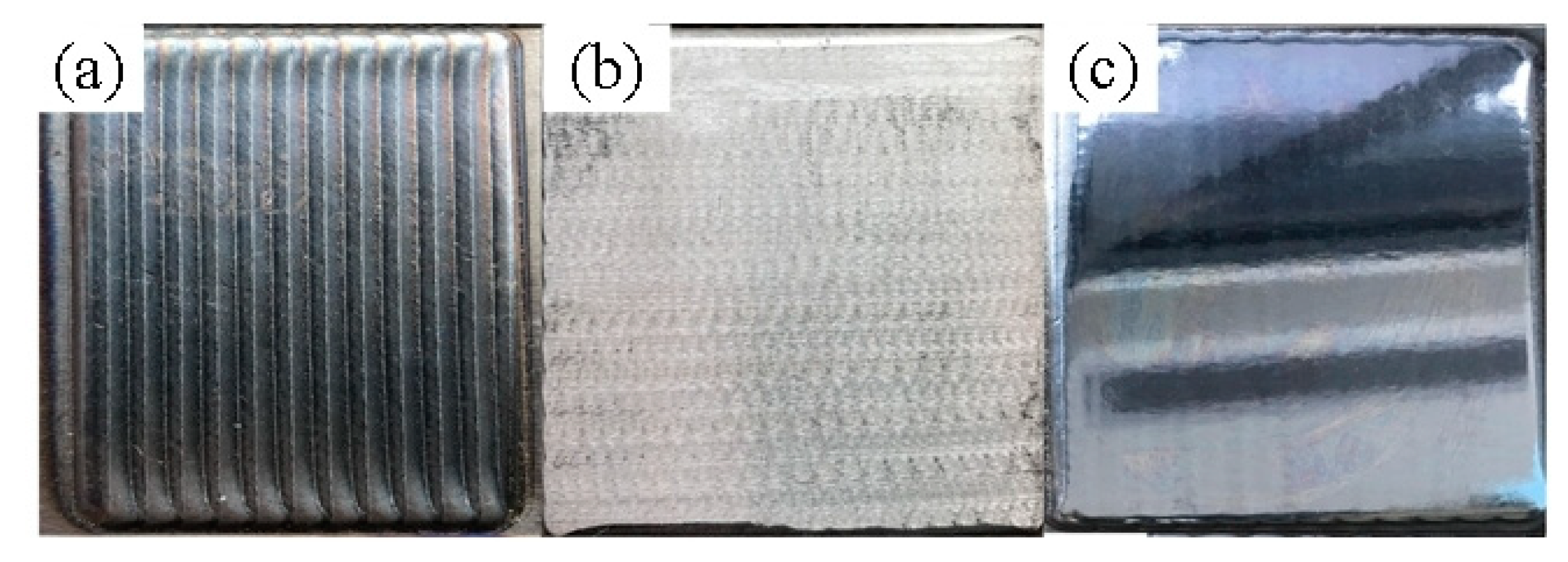
Subsequently, several samples were treated with three USRPs at room temperature. For the ultrasonic processing, the drum diameter was 12 mm, the ultrasonic vibration frequency was 30 kHz, the oscillation amplitude was 10 μm, and the applied static force was 200 N. The ultrasonic rolling parameters were chosen based on earlier research on ultrasonic rolling of cobalt-based alloys [18]. The schematic diagram of the ultrasonic rolling implementation device is shown in Figure 2. The principle of the ultrasonic rolling process and the processed samples are shown in Figure 3 and Figure 4, respectively.
2.2. Characterization of the Coatings
The frictional wear performance of each specimen was examined using an HT-1000 high-temperature friction and wear testing machine before and after rolling at 600 °C. Surface flaws on the worn samples were removed using sandpaper; the samples were then cleaned with alcohol before testing. The following experimental parameters were used: a grinding-ball rotation radius of 4 mm, a load of 7 N, a wear time of 30 min, and a grinding-ball diameter of 5 mm. The counter-abrasive material was Si3N4. The friction-wear samples were scanned and modeled using a DSX1000 digital microscope. The wear cross-sections before and after rolling were calculated and analyzed by scanning the samples with a depth-of-field camera.
The cross-sections of the samples were polished by MTP-200 metallographic grinding and polishing machine. These were then polished with SiO2 abrasive paste, etched with aqua regia, and analyzed in terms of the physical phase using an X-ray diffractometer (XRD; Bruker, D8-Advanced). The target used for XRD testing was a copper target with a voltage of 40 kV, a current of 30 mA, and diffraction angles of 20°–100°. The surfaces of the samples were cleaned with ethanol by an ultrasonic cleaner for 5 min before being etched with an aqua regia solution (HCl:HNO3 = 3:1) for 60 s to study the microstructure. To remove any residual solution and contaminants, the etched samples were washed with an ethanol solution. A scanning electron microscope (FESEM; Quanta 250) was used to analyze the microstructure of the samples.
A Vickers microhardness tester (HVS-1000) was used to measure the microhardness along the cross-sectional depth of the coating under a load of 3 N and a dwell time of 15 s. A series of test values were used to determine the microhardness distribution along the vertical coating direction. The vertical distance between the consecutive test areas was constantly maintained at 50 μm. The average result was obtained after each test had been conducted three times along the same horizontal line. The main sources of errors in the microhardness measurements were errors in the load, errors in the dwell-time control, errors in the flatness of the specimen surface, and errors in the calculation of the area of indentations.
3. Results and Discussion
3.1. Microstructure and Physical Phase Analysis
The coating of IN 718 was mainly composed of a γ-(Fe, Ni) solid solution and co-crystal tissues (Laves phase). The atomic radii of Ni and Fe are close and the Ni atoms could easily replace Fe atoms in γ-Fe to form displaced solid solutions. Due to its inherent elemental separation behavior, IN 718 usually forms a large number of low-melting point co-crystal compounds in the last cured tree frame [19]—the so-called Laves phase—which is usually harmful to the mechanical properties of the coating.
Figure 5 shows the cross-sectional FESEM images of the IN 718 coating over the entire cladding width, including the melted layer, the white band of the adhesion area, and the interface with the substrate which was mainly composed of planar crystals. The coating bonded well to the substrate and there were no obvious cracks in the coating. There were a few small holes in the middle and lower parts of the coating. The size of these pores was not large; they may have been caused by the incomplete escape of gas in the molten pool. According to the supercooling theory [20] proposed by Tiller, the formation of a microscopic tissue morphology during solidification is mainly affected by the ratio of the temperature gradient G and the solidification rate R at the solid–liquid interface. A decrease in the G/R value facilitates the formation of equiaxed grains. The solidification rate R and the laser scanning speed V were calculated as follows [21]:
where α is the angle between the laser scanning direction and the normal molten pool boundary. G at the bottom of the molten pool was slightly lower but R at the bottom was close to 0; thus, G/R reached a maximum value. As shown in Figure 5d, the bottom of the coating was mainly relatively thick columnar crystals. The GR value in the middle region of the coating decreased, forming cellular crystals and shorter columnar dendrites. These were well developed, as shown in Figure 5c. The α-value of the top region tended to be 0, indicating the smallest G/R at the liquid–gas interface in the top region. This led to the coexistence of extremely short and equiaxed grains, as shown in Figure 5b.
The EDS method is utilized in this research to examine the element composition of the two phases of IN718 in Figure 6. The EDS test determined the elements Fe, Ni, Cr, Nb, Al, Ti, Mo, Mn, and Si. According to Table 3, the mass fraction of Nb in phase A might reach 21.8%. In phase B, the mass fraction of Nb is only 0.31%. Because the average niobium level in IN 718 superalloy is roughly 5.25% (Table 2), phase A is judged to be the Laves phase. The element composition of phase B is comparable to that of powder element, indicating that phase B is the matrix phase. As a result, in the solidified IN 718 alloy, niobium segregation occurs. According to NIE et al. [22], the high concentration of Nb in the interdendritic zone promotes the establishment of Nb-rich Laves phase. After laser cladding, IN718 features a Laves phase between dendrites. The Laves phase is thought to be an intermetallic compound phase with a topologically close-packed structure. It possesses less than five independent slip systems, which is common for brittle phases, and it is very resistant to dislocations. It can improve the hardness of the material to some amount. When the stress level from dislocation pile-up is high the Laves phase is easily ruptured, reducing the alloy’s strength and flexibility. As a result, superalloys strive to avoid the precipitation of hazardous phases such as the Laves phase [23]. The mechanical characteristics of the Laves of various sizes and forms varied significantly [24].
Figure 7a shows the microstructure diagram of the coating after USRP. Region A was approximately 12 μm high and exhibited severe plastic deformation. Slight plastic deformation occurred within the B region. After scanning electron microscopy observations and measurements, the height of region B was approximately 40 μm. Figure 7b,c shows the top area of the coating before and after USRP, demonstrating that the top had severe plastic deformation of the coating after USRP. It is well known that severe plastic deformation facilitates fine-grained metal materials whilst improving mechanical properties such as microhardness and strength. Plastic deformation can refine the grain and increase the dislocation density. Displaced slip, accumulation, and rearrangement can lead to the formation of small-angle grain boundaries and substructures, improving the mechanical properties [25]. Under the dual action of static pressure and ultrasonic vibration, the surface and grains of the samples treated with USRP were squeezed and extended. The top of the surface was severely deformed, the grains were extruded and elongated, and the growth direction was parallel to the machining surface. Figure 7d shows the local magnification view of region B. The red lines in Figure 5b and Figure 7d represent the approximate direction of the grain growth. The grain growth direction in Figure 5b is more vertical; that in Figure 7d is closer to the horizontal direction. The horizontal direction was the machining direction; thus, the grain growth direction in the slightly deformed area changed from the ultrasonic rolling to the machining direction. As Figure 7d demonstrates, the length of the crystal significantly shortened, the length of most dendritical crystals reduced to less than 10 μm, and the grain size significantly reduced. At greater depths of the deposited composite layer, a decrease in the effect of plastic deformation produced by ultrasonic lamination was observed. The static pressure and ultrasonic vibration were greatly attenuated in the middle of the coating. The microstructure was almost unaffected; there was no significant change compared with before USRP. Similarly, the bottom of the coating remained intact.
Figure 8 shows the XRD diffraction profile of the front and rear coating of USRP. The γ-(Fe, Ni) phase was the matrix phase in the IN 718 cladding layer. As IN 718 is a supersaturation alloy, the γ′ phase and the γ phase were close to the dot matrix constant; the mismatch was only approximately 0.4%. This was co-localized with the matrix; thus, there was a basic overlap with the γ diffraction peak [26]. The common precipitated phases of IN 718 (such as the Laves and δ phases) did not clearly show their diffraction lines in the XRD spectrum due to their limited content. According to the literature [27], the diffraction peak of XRD is significantly widened; the change in the half-height width of the diffraction peak caused by the rolling treatment was mainly caused by the grain size. The grain size was calculated using the Scheele formula as follows:
where D represents the grain size (nm); k represents a constant, generally 1; λ represents the wavelength of X-rays (nm); β represents the half-height width of the diffraction peak (rad); and θ represents the half-diffraction angle (rad). The diffraction peak half-height width and the diffraction intensity peak of the rolled samples were compared with the samples without ultrasonic surface rolling process using the JADE. As per the Scheele formula, the coating grain size decreased. This indicated that USRP could refine the grain [28]. According to the theory of [29], the change in the phase structure of metal materials is mainly affected by the elemental composition of the material and the cooling conditions of the metal solidification process. In this experiment, only the coating was rolled; no other elements were introduced and the cooling conditions did not change. Thus, the phase composition of the superalloy coating did not change after rolling.
3.2. Microhardness
Figure 9 shows the microhardness curves of the coating before and after the rolling treatment. The average hardness value of the IN 718 milling sample was 294.05 HV. The average hardness value after the USRP of the IN 718 milling sample was 383.66 HV, an increase in approximately 30% compared with the average hardness of 264.68 HV of the H13 substrate. The main reason for the increase in hardness was the process of hardening during rolling due to the plastic flow on the material surface. The tool head vibrated the sample surface with a high frequency under a certain static load, creating a plastic flow on the rolling sample surface and compacting the coating structure. Hardness is defined as the ability of a material to resist plastic deformation. The smaller the grain size in a microstructure, the greater the grain boundaries and resistance to the plastic flow [30]. Plastic deformation and residual stress increasing produce a significant amount of dislocation nucleation [31] which improves the material’s deformation resistance and increases the hardness of the coated surface following ultrasonic surface rolling. The increase in hardness was due to the combined strengthening effect of deformation hardening and the fine-grain strengthening effect. The relationship between Hall–Petch (refined particles) and Taylor (dense dislocation) is provided by Equation (2) [32] as follows:
where σs is the yield strength of the material; σ0 is the friction force to be overcome to move a single dislocation; d is the average grain size; and k is a constant. According to Equation (3), σs is inversely proportional to d. On the top of the coating, the grains of the coated tissue grew in directions parallel to the plastic flow direction, mainly as equiaxed grains. In the crystal dislocation motion, the smaller-sized grains formed a greater number of dislocation walls and exhibited dislocation entanglement. Thus, the dislocation significantly changed and the yield strength was larger [33]. The fine grains and phase dispersion could be strengthened by high-frequency vibrations, improving the hardness and yield strength [34]. The harder the coating, the better its ability to resist plastic formation.
3.3. High-Temperature Friction and Wear Resistance
Figure 10 is the friction coefficient curve. The friction coefficient fluctuates greatly in the first 8 min of the experiment and enters the stable friction stage after 8 min. The experimental data after eight minutes were selected for comparison. The average friction coefficient of IN 718 before USRP is 0.390. The average friction coefficient of IN 718 decreased to 0.364 after USRP. In addition, the friction coefficients of the two coatings were significantly smaller than that of the H13 substrate.
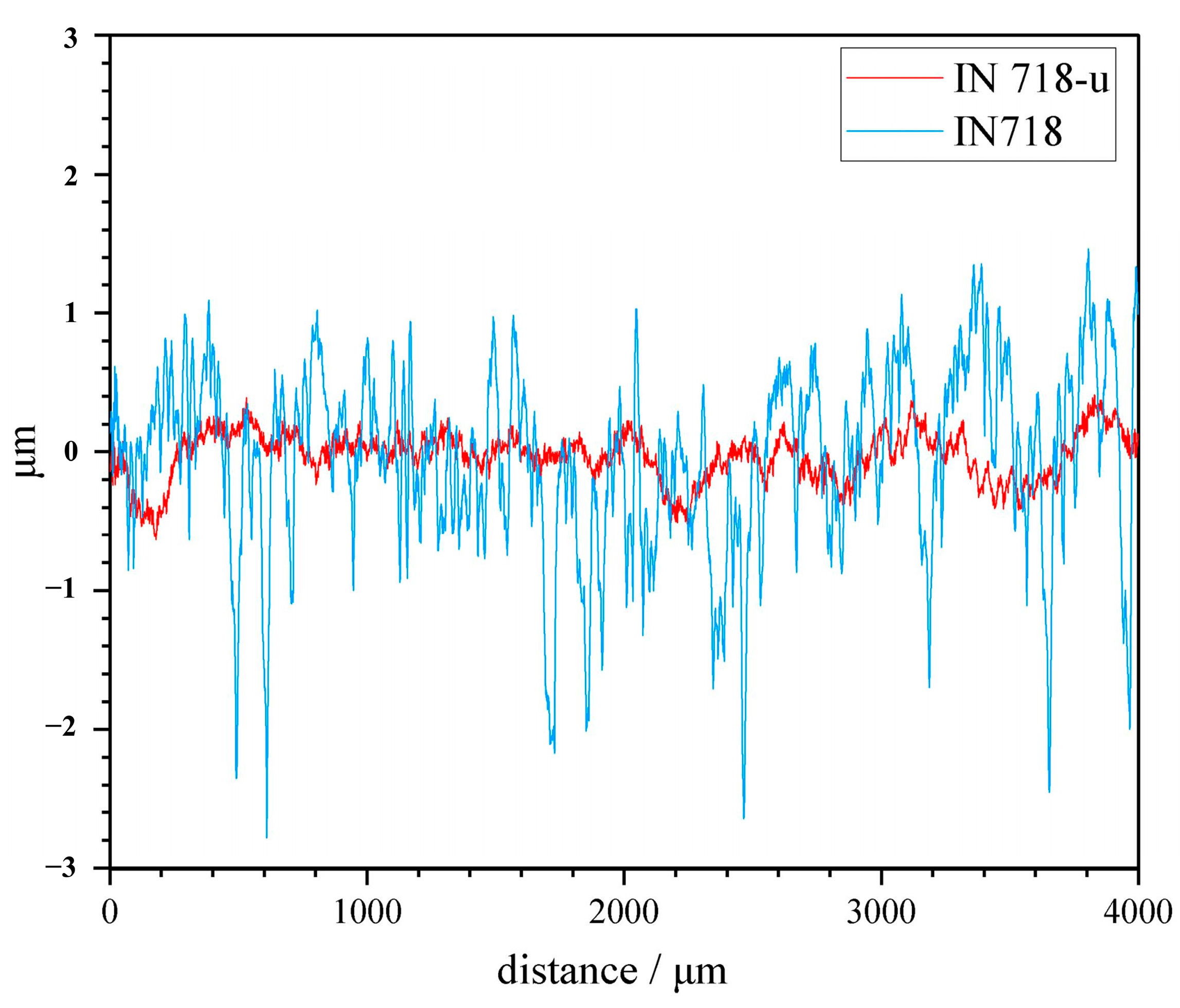
Figure 11 shows the surface roughness of the worn sample. The average surface roughness of the coating without USRP is 0.502 μm. After USRP, the surface roughness of IN 718 decreased to 0.137 μm. It can be seen that USRP can significantly reduce the surface roughness of the coating. Plastic flow occurs on the surface of the metal material due to the high-frequency vibration of the ultrasonic tool head, causing the original uneven surface to achieve the effect of cutting peak and filling a valley, reducing the roughness value of the coating surface. The surface of the material and the contact area increased and the normal pressure reduced. Thus, the friction-wear-process running stage and the friction coefficient were reduced, improving the wear resistance of the coating.
Three-dimensional contour modeling was performed using a DSX1000 digital microscope. Friction-wear samples were scanned using a depth-of-field camera to quantify the wear volume before and after USRP. The scans are shown in Figure 12, where Figure 12a (IN 718) indicates the coating without USRP and Figure 12b (IN 718) represents the coating after USRP. With five isometric cross-sections as reference values, the cross-section area of IN 718 before USRP was 9534.99 (μm)2; after rolling, it was 6296.87 (μm)2. According to the volume equation V = SL, where the radius of friction φ = 4 mm and L = 25,133 μm, the wear rate was calculated, as shown in Figure 13. Figure 13 demonstrates that the wear resistance of the coating after laser cladding significantly improved compared with the substrate, especially after USRP. The wear rate of the coating after USRP was 4.99 × 10⁻⁴ mm3/(Nm). The wear rate of the coating without USRP was 7.56 × 10⁻⁴ mm3/(Nm). After USRP, the wear rate of the coating decreased by 51%. Thus, USRP improved the wear resistance of the coating.
Figure 14 shows the high-temperature wear morphology of the front and rear USRP coatings. The wear pattern of the samples after USRP clearly improved after the high-temperature friction-wear experiment. The USRP front-wear width was 776.44 μm. The wear surface of the IN 718 sample before USRP covered a wide area and had a large depth with the presence of an unstripped oxide layer and a large number of adhesive layers. There were many furrows parallel to the wear direction and debris accumulated on the wear surface. All these phenomena indicated that severe adhesive wear and grinding wear occurred in the coating during high-temperature sliding wear, accompanied by oxidative wear. This resulted in a relatively high friction coefficient and wear rate of the coating. After USRP, the wear width was substantially reduced to 622.22 mm. Shallow adhesive pits were observed on the wear surface with significantly fewer unshed oxide layers. This was because the large strain and strain rate applied by the ultrasonic rolling process caused violent plastic deformation as well as the grain refinement and strength improvement of the coating surface. This enhanced the plastic deformation resistance of the coating. The plastic deformation of the surface after USRP in the friction-wear process was more difficult and the surface material was less likely to separate; that is, the difficulty of the adhesive wear phenomenon increased, thus improving the wear resistance of the coating surface. As shown in Figure 9, the surface hardness of the coating after USRP significantly improved. We used the wear theory of Holm and Archards [35] as follows:
where V is the amount of wear, S is the wear distance, W is the load, and H is the hardness of the material. According to the formula, the coating wear amount after USRP should have been reduced and the coating wear rate should have decreased.
The degree of adhesive and abrasive wear of the coating is greatly reduced after USRP, which eventually leads to a reduction in the quantity of grinding. As can be observed, USRP may effectively lower the wear rate of the IN718 coating, enhancing its wear resistance.
4. Conclusions
A nickel-based (IN 718) coating was prepared on the surface of H13 die steel using high-speed laser cladding. Subsequently, the cladding was ultrasonically rolled. The influence of the ultrasonic rolling surface modification on the coating microstructure and wear resistance was studied using observations of the coating microtissue and a high-temperature friction–wear test. The research results demonstrated the applicability of ultrasonic surface rolling technology in the field of high-temperature-alloy laser-clad layers, improving the wear resistance of high-temperature alloys and improving their life. We present the following conclusions:
- (1)
- The microstructure close to the top of the coating surface was composed of fine dendrites and equiaxed crystals. The middle tissue of the coating was composed of dendrite crystals and cell crystals. The microstructure at the bottom of the coating was mainly coarse columnar crystals. Planar crystals appeared at the junction between the bottom of the coating and the substrate. The Laves phase was often distributed in the IN 718-coated interdendritic channels;
- (2)
- Under the dual action of static pressure and ultrasonic vibration, the top of the IN 718 coating after USRP produced a sharp deformed area of approximately 12 μm. The particles were extruded and elongated; the growth direction was parallel to the processed surface. Minor plastic deformation occurred within 40 μm of the severely deformed area. The growth direction of the grain was also affected and had an obvious trend towards the machining direction;
- (3)
- After USRP, the phase composition of the IN 718 coating did not significantly change. γ-(Fe, Ni) was dominant; the other phases had a low content and no obvious diffraction peak. The half-height width of the diffraction peak increased after USRP;
- (4)
- The coating hardness substantially increased after USRP, from 294.05 HV to 383.66 HV. Thanks to the increased surface hardness and reduced grain size after USRP, the surface roughness of the coating was greatly reduced. The coating wear rate reduced and changed from severe adhesive wear and abrasive wear to slight adhesive wear and insignificant abrasive wear.
Author Contributions
Conceptualization, Q.N.; writing—original draft preparation, J.H.; investigation, H.J.; writing—review and editing, Q.N. and J.H.; metrology, H.L. All authors have read and agreed to the published version of the manuscript.
Funding
Fundamental Research Funds for the Central Universities (2020ZDPYMS22), Priority Academic Program Development of Jiangsu Higher Education Institutions (PAPD).
Institutional Review Board Statement
Not applicable.
Informed Consent Statement
Not applicable.
Data Availability Statement
The data presented in this study are available on request from the corresponding author.
Acknowledgments
This work was supported by the Fundamental Research Funds for the Central Universities (2020ZDPYMS22), a project funded by the Priority Academic Program Development of Jiangsu Higher Education Institutions (PAPD). The authors are grateful for the support of the Advanced Analysis and Computation Center, China University of Mining and Technology, for providing the X-ray diffraction equipment (Bruker, D8 Advance) and the scanning electron microscope (FESEM, Quanta 250).
Conflicts of Interest
The authors declare no conflict of interest.
References
- Wang, J.T.; Liu, S.P.; Fan, Y.P.; He, Z.R. A short review on selective laser melting of H13 steel. Int. J. Adv. Manuf. Technol. 2020, 108, 453–2466. [Google Scholar] [CrossRef]
- Qu, H.; Tang, C.; Gu, T. Research on microstructure and high-temperature friction and wear properties of a cobalt-based alloy for hot extrusion die. Baosteel Tech. Res. 2020, 14, 10–20. [Google Scholar]
- DebRoy, T.; Wei, H.L.; Zuback, J.S.; Mukherjee, T.; Elmer, J.W.; Milewski, J.O.; Beese, A.M.; Wilson-Heid, A.; De, A.; Zhang, W. Additive manufacturing of metallic components—Process, structure and properties. Prog. Mater. Sci. 2017, 92, 112–224. [Google Scholar] [CrossRef]
- Wu, Y.; Liu, Y.; Chen, W.J. Research status and development direction of extreme high-speed laser material deposition. Electr. Weld. Mach. 2020, 50, 109800. [Google Scholar]
- Schopphoven, T.; Gasser, A.; Wissenbach, K.; Poprawe, R. Investigations on ultra-high-speed laser material deposition as alternative for hard chrome plating and thermal spraying. J. Laser Appl. 2016, 28, 022501. [Google Scholar] [CrossRef]
- Li, L.; Shen, F.; Zhou, Y.; Tao, W.; Wang, W.; Wang, S. Comparison of Microstructure and Corrosion Resistance of 431 Stainless Steel Coatings Prepared by Extreme High-Speed Laser Cladding and Conventional Laser Cladding. Chin. J. Lasers 2019, 46, 1002010. [Google Scholar]
- Yan, Q.; Yang, K.; Wang, Z.D.; Chen, M.Z.; Sun, G.F.; Ni, Z.H. Surface roughness optimization and high-temperature wear performance of H13 coating fabricated by extreme high-speed laser cladding. Opt. Laser Technol. 2022, 149, 107823. [Google Scholar] [CrossRef]
- Kou, S.Q.; Dai, J.N.; Wang, W.X.; Zhang, C.K.; Wang, S.Y.; Li, T.Y.; Chang, F. Enhancement of Wear Resistance on H13 Tool and Die Steels by Trace Nanoparticles. Metals 2022, 12, 348. [Google Scholar] [CrossRef]
- Yuan, X.; Wang, J.; Zhu, Q.H. Microstructure and wear resistance of iron-based and cobalt-based cladding layers of H13 steel. Trans. CHINA Weld. Inst. 2018, 39, 105–109. [Google Scholar]
- Hosseini, E.; Popovich, V.A. A review of mechanical properties of additively manufactured Inconel 718. Addit. Manuf. 2019, 30, 100877. [Google Scholar] [CrossRef]
- Liu, M.; Li, J.Y.; Ma, Y.; Yuan, T.Y.; Mei, Q.S. Surface nanocrystallization and property of Ti6Al4V alloy induced by high pressure surface rolling. Surf. Coat. Technol. 2016, 289, 94–100. [Google Scholar] [CrossRef]
- Wang, H.; Song, G.; Tang, G. Evolution of surface mechanical properties and microstructure of Ti6Al4V alloy induced by electropulsing-assisted ultrasonic surface rolling process. J. Alloys Compd. 2016, 681, 146–156. [Google Scholar] [CrossRef]
- Bozdana, A.T.; Gindy, N.N.Z. Comparative experimental study on effects of conventional and ultrasonic deep cold rolling processes on Ti6Al4V. Mater. Sci. Technol. 2008, 24, 1378–1384. [Google Scholar] [CrossRef]
- Ye, H.; Zhu, J.; Liu, Y.; Liu, W.; Wang, D. Microstructure and mechanical properties of laser cladded CrNi alloy by hard turning (HT) and ultrasonic surface rolling (USR). Surf. Coat. Technol. 2020, 393, 125806. [Google Scholar] [CrossRef]
- Amanov, A.; Cho, I.S.; Kim, D.E.; Pyun, Y.S. Fretting wear and friction reduction of CP titanium and Ti6Al4V alloy by ultrasonic nanocrystalline surface modification. Surf. Coat. Technol. 2012, 207, 135–142. [Google Scholar] [CrossRef]
- Tan, L.; Yao, C.; Zhang, D.; Ren, J.; Shen, X. Effects of different mechanical surface treatments on surface integrity of TC17 alloys. Surf. Coat. Technol. 2020, 398, 126073. [Google Scholar] [CrossRef]
- Hao, J.; Hu, F.; Le, X.; Liu, H.; Yang, H.; Han, J. Microstructure and high-temperature wear behaviour of Inconel 625 multi-layer cladding prepared on H13 mould steel by a hybrid additive manufacturing method. J. Mater. Process. Technol. 2021, 291, 117036. [Google Scholar] [CrossRef]
- Ji, H.W.; Hao, J.B.; Liu, Q.W.; Liu, H.; Yang, H.F.; Liu, X.H. Effect of Ultrasonic Rolling on Microstructure and Mechanical Properties of GH5188 High-temperature Alloy Coatings by High-speed Laser Cladding. J. Netshape Form. Eng. 2022, 15, 146–155. [Google Scholar]
- Liu, S.; Liu, D. Effect of hard phase content on the mechanical properties of TiC-316 L stainless steel cermets. Int. J. Refract. Met. Hard Mater. 2019, 82, 273–278. [Google Scholar] [CrossRef]
- Tiller, W.A.; Jackson, K.A.; Rutter, J.W.; Chalmers, B. The redistribution of solute atoms during the solidification of metals. Acta Metall. 1953, 1, 46–55. [Google Scholar] [CrossRef]
- Gan, Z.; Yu, G.; He, X.; Li, S. Numerical simulation of thermal behavior and multicomponent mass transfer in direct laser deposition of Co-base alloy on steel. Int. J. Heat Mass Transf. 2017, 104, 28–38. [Google Scholar] [CrossRef] [Green Version]
- Nie, P.; Ojo, O.A.; Li, Z. Numerical modeling of microstructure evolution during laser additive manufacturing of a nickel-based superalloy. Acta Mater. 2014, 77, 85–95. [Google Scholar] [CrossRef]
- Sui, S.; Chen, J.; Fan, E.; Yang, H.; Lin, X.; Huang, W. The influence of Laves phases on the high-cycle fatigue behavior of laser additive manufactured Inconel 718. Mater. Sci. Eng. A 2017, 695, 6–13. [Google Scholar] [CrossRef]
- Sui, S.; Tan, H.; Chen, J.; Zhong, C.; Li, Z.; Fan, W.; Gasser, A.; Huang, W. The influence of Laves phases on the room temperature tensile properties of Inconel 718 fabricated by powder feeding laser additive manufacturing. Acta Mater. 2019, 164, 413–427. [Google Scholar] [CrossRef]
- Paul, C.P.; Mishra, S.K.; Tiwari, P.; Kukreja, L.M. Solid-particle erosion behaviour of WC/Ni composite clad layers with different contents of WC particles. Opt. Laser Technol. 2013, 50, 155–162. [Google Scholar] [CrossRef]
- Ren, Z.; Lai, F.; Qu, S.; Zhang, Y.; Li, X.; Yang, C. Effect of ultrasonic surface rolling on surface layer properties and fretting wear properties of titanium alloy Ti5Al4Mo6V2Nb1Fe. Surf. Coat. Technol. 2020, 389, 125612. [Google Scholar] [CrossRef]
- Chen, X.; Dai, X.; Qian, H.; Yang, B.; Zhao, J. Effects of surface nanocrystallization on the oxide film formed on 316LN stainless steel in a high-temperature aqueous environment. Mater. Corros. 2022, 73, 125–133. [Google Scholar] [CrossRef]
- Amanov, A.; Umarov, R. The effects of ultrasonic nanocrystal surface modification temperature on the mechanical properties and fretting wear resistance of IN 690 alloy. Appl. Surf. Sci. 2018, 441, 515–529. [Google Scholar] [CrossRef]
- Hua, Y.X. Introduction to Metallurgical Process Kinetics, 1st ed.; Metallurgical Industry Press: Beijing, China, 2004; Volume 11, pp. 82–94. [Google Scholar]
- Liu, W.H.; Lu, Z.P.; He, J.Y.; Luan, J.H.; Wang, Z.J.; Liu, B.; Liu, Y.; Cheen, M.W.; Liu, C.T. Ductile CoCrFeNiMox high entropyalloys strengthened by hard intermetallic phases. Acta Mater. 2016, 116, 332–342. [Google Scholar] [CrossRef]
- Wang, B.; Xu, W.; Zhou, X.; Li, X.Y.; Qiao, J.S. Formation of stable equiaxial nanograined Al via combined plastic deformation. Scr. Mater. 2021, 203, 114054. [Google Scholar] [CrossRef]
- Bahl, S.; Suwas, S.; Ungar, T.; Chatterjee, K. Elucidating microstructural evolution and strengthening mechanisms in nanocrystalline surface induced by surface mechanical attrition treatment of stainless steel. Acta Mater. 2017, 122, 138–151. [Google Scholar] [CrossRef]
- Wang, G.; Croaker, P.; Dargusch, M.; McGuckin, D. Simulation of convective flow and thermal conditions during ultrasonic treatment of an Al-2Cu alloy. Comput. Mater. Sci. 2017, 134, 116–125. [Google Scholar] [CrossRef] [Green Version]
- Qiu, Z.; Zhang, P.; Wei, D. Tribological behavior of CrCoNiAlTiY coating synthesized by double-glow plasma surface alloying technique. Tribol. Int. 2015, 92, 512–518. [Google Scholar] [CrossRef]
- Yingxia, Y.; Bolin, H.; Zongmin, L.; Siyong, L.; Songsong, X. Experimental Research on Microhardness and Wear Resistance of MB8 Magnesium Alloy Treated by Ultrasonic Impact. Rare Met. Mater. Eng. 2017, 46, 1798–1802. [Google Scholar] [CrossRef] [Green Version]
Figure 1.
IN 718 powder shape.

Figure 2.
Schematic diagram of the ultrasonic surface rolling process implementation device.

Figure 3.
Schematic of the ultrasonic surface rolling process.

Figure 4.
Processed samples: (a) after laser cladding; (b) after milling; and (c) after USRP.

Figure 5.
FESEM images of the IN 718 superalloy coating: (a) surface area of the coating; (b) top area of the coating; (c) middle area of the coating; and (d) lower area of the coating.
Figure 5.
FESEM images of the IN 718 superalloy coating: (a) surface area of the coating; (b) top area of the coating; (c) middle area of the coating; and (d) lower area of the coating.

Figure 6.
Local FESEM images of in 718 coating.

Figure 7.
FESEM images of coating: (a) IN 718 coating after USRP; (b) top after USRP; (c) top without USRP; and (d) 30 μm from the surface after USRP.
Figure 7.
FESEM images of coating: (a) IN 718 coating after USRP; (b) top after USRP; (c) top without USRP; and (d) 30 μm from the surface after USRP.

Figure 8.
XRD diffraction pattern before and after the IN 718-coated USRP.

Figure 9.
Microhardness curves of the coatings.

Figure 10.
Friction coefficient curve of the coatings.

Figure 11.
Surface roughness of the coatings.

Figure 12.
Three-dimensional profile of high-temperature wear form: (a) without USRP and (b) after USRP.
Figure 12.
Three-dimensional profile of high-temperature wear form: (a) without USRP and (b) after USRP.

Figure 13.
Histogram of wear rate.

Figure 14.
Wear morphology of superalloy coating: (a,b) without USRP and (c,d) after USRP.


Table 1.
ZKZM-6000 high-speed laser parameters.
| Performance | Parameters |
|---|---|
| Output power | 6000 w |
| Spot diameter | 5 mm |
| Focal length | 280 mm |
| Powder-feeding capacity | 6~150 g/min |
Table 2.
IN 718 nickel-based alloy powder composition.
| Element | Ni | Cr | Mo | Nb | Fe | Si | Al | Ti | Mn |
|---|---|---|---|---|---|---|---|---|---|
| content (wt.%) | 50.00 | 19.00 | 3.05 | 5.25 | Balance | 0.35 | 0.5 | 0.9 | 0.35 |
Table 3.
The element content of point A and point B.
| Point | Element | Ni | Cr | Mo | Nb | Fe | Si | Al | Ti | Mn |
|---|---|---|---|---|---|---|---|---|---|---|
| A | Content(wt.%) | 45.42 | 16.08 | 2.10 | 21.8 | 11.25 | 1.26 | 0.50 | 1.26 | 0.33 |
| B | Content(wt.%) | 53.64 | 19.12 | 2.21 | 0.31 | 21.82 | 0.37 | 0.48 | 0.80 | 0.35 |
Disclaimer/Publisher’s Note: The statements, opinions and data contained in all publications are solely those of the individual author(s) and contributor(s) and not of MDPI and/or the editor(s). MDPI and/or the editor(s) disclaim responsibility for any injury to people or property resulting from any ideas, methods, instructions or products referred to in the content. |
© 2023 by the authors. Licensee MDPI, Basel, Switzerland. This article is an open access article distributed under the terms and conditions of the Creative Commons Attribution (CC BY) license (https://creativecommons.org/licenses/by/4.0/).
Share and Cite
MDPI and ACS Style
Hao, J.; Niu, Q.; Ji, H.; Liu, H. Effect of Ultrasonic Rolling on the Organization and Properties of a High-Speed Laser Cladding IN 718 Superalloy Coating. Crystals 2023, 13, 1214. https://doi.org/10.3390/cryst13081214
AMA Style
Hao J, Niu Q, Ji H, Liu H. Effect of Ultrasonic Rolling on the Organization and Properties of a High-Speed Laser Cladding IN 718 Superalloy Coating. Crystals. 2023; 13(8):1214. https://doi.org/10.3390/cryst13081214
Chicago/Turabian StyleHao, Jingbin, Qingwei Niu, Haowen Ji, and Hao Liu. 2023. "Effect of Ultrasonic Rolling on the Organization and Properties of a High-Speed Laser Cladding IN 718 Superalloy Coating" Crystals 13, no. 8: 1214. https://doi.org/10.3390/cryst13081214
Note that from the first issue of 2016, this journal uses article numbers instead of page numbers. See further details here.