Rare-Earth Calcium Oxyborate Piezoelectric Crystals ReCa4O(BO3)3: Growth and Piezoelectric Characterizations


Abstract
:
1. Introduction

| Symmetry | Crystals | Growth Method | Tc/Tm (°C) | deff (pC/N) |
|---|---|---|---|---|
| Trigonal | LGS | Cz | 1430 [39] | 6~7 |
| CTGS | Cz | ~1370 [40] | ~10 | |
| CTAS | Cz | – | ~5 | |
| GaPO4 | Flux/hydrothermal | 970 [41] # | ~5 | |
| LN | Cz | 1150 | ~70 [42] | |
| Tetragonal | SLG | Cz | ~1650 [43] | ~14 [44] |
| CAS | Cz | 1500 | ~6 [22] | |
| BTS | Cz | 1445 | ~18 [23] | |
| Monoclinic | ReCOB | Cz/Bridgman | 1400~1520 [1] | ~15 |
2. Crystal Growth
2.1. Polycrystalline Preparation
2.2. Approaches for ReCOB Crystal Growth
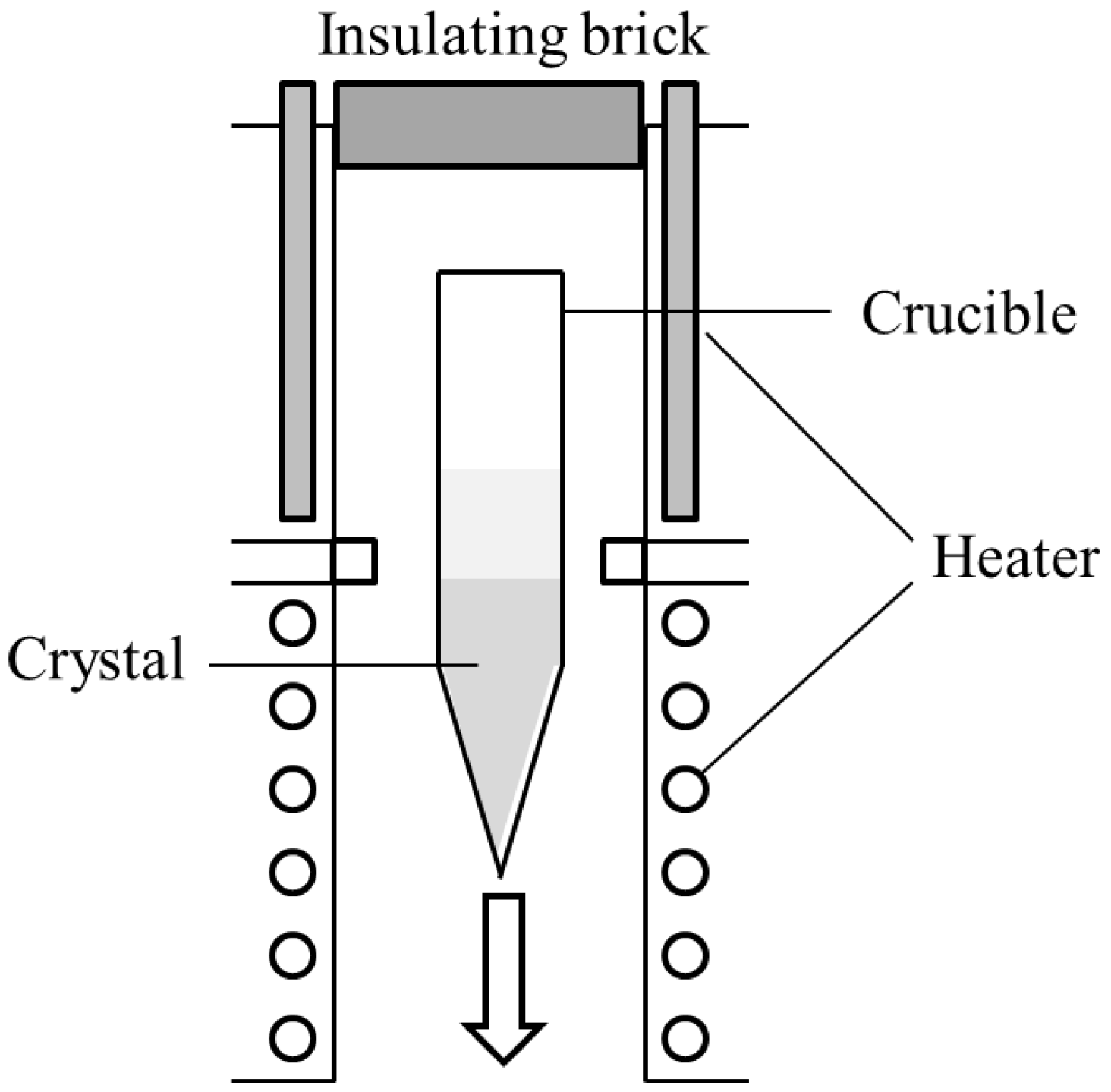
2.2.1. Bridgman Method

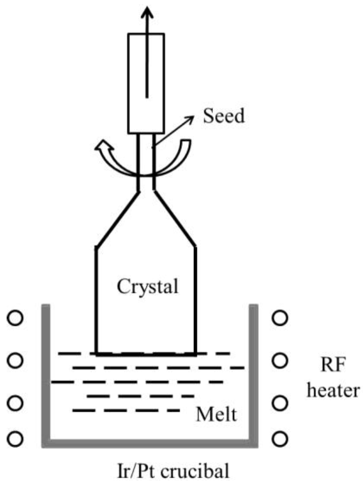
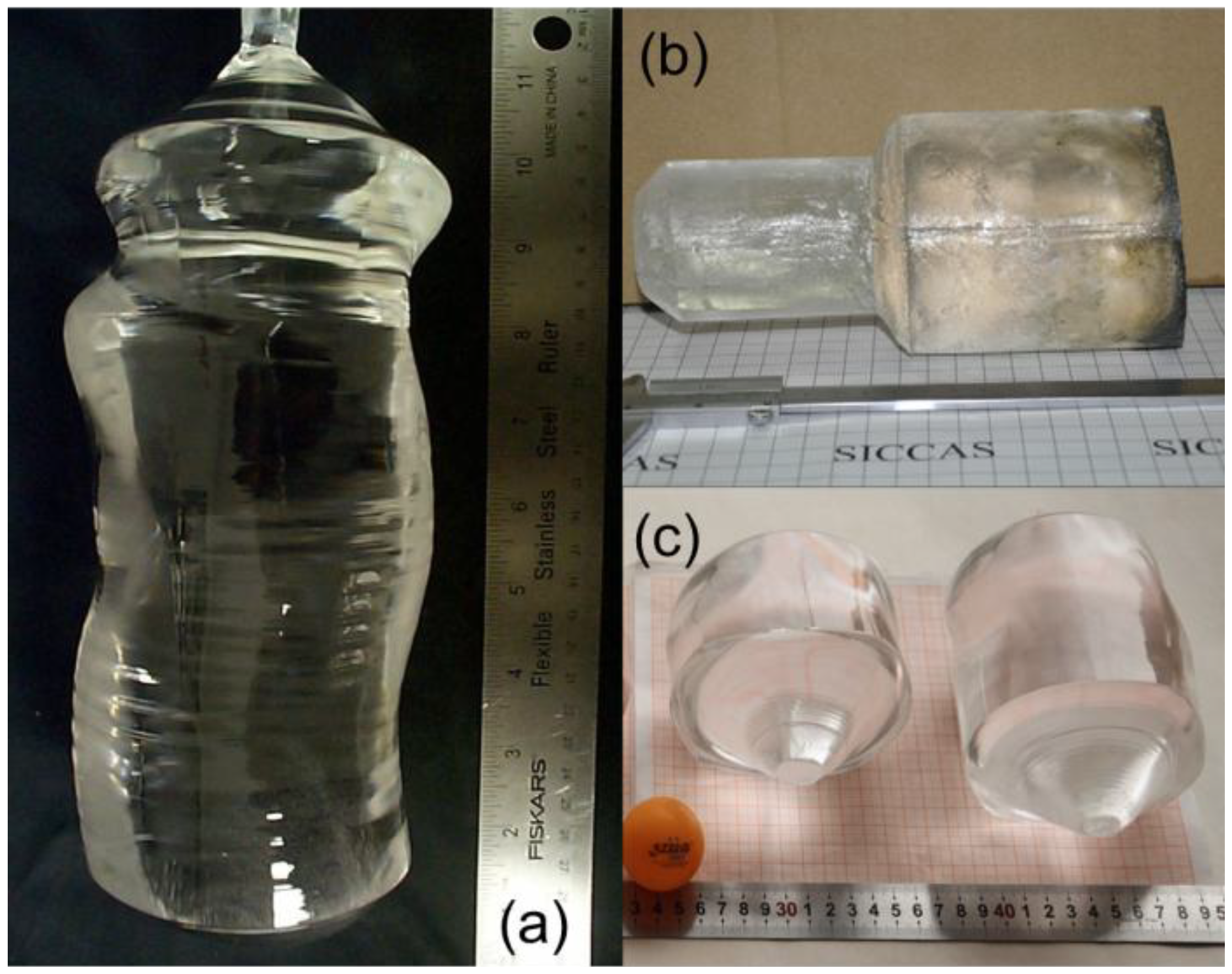
2.2.2. Cz Pulling Method


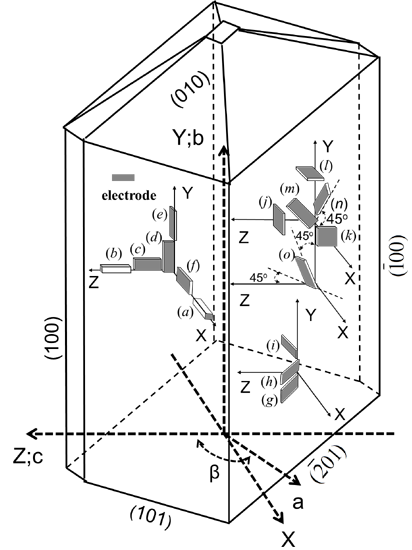
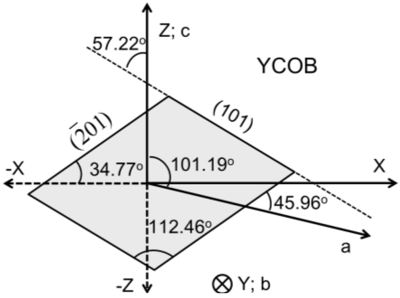
3. Orientation of Monoclinic ReCOB Crystals

| Crystals | TmCOB | ErCOB | YCOB | TbCOB | GdCOB | SmCOB | NdCOB | PrCOB | LaCOB | |
|---|---|---|---|---|---|---|---|---|---|---|
| Parameters (Å/Å3/°) * | a | 8.068 | 8.075 | 8.078 | 8.072 | 8.104 | 8.114 | 8.145 | 8.177 | 8.173 |
| b | 16.01 | 16.01 | 16.02 | 16.00 | 16.03 | 16.06 | 16.07 | 16.16 | 16.09 | |
| c | 3.522 | 3.530 | 3.534 | 3.545 | 3.558 | 3.579 | 3.607 | 3.629 | 3.627 | |
| β | 101.11 | 101.43 | 101.19 | 101.25 | 101.25 | 101.38 | 101.37 | 101.40 | 101.40 | |
| V | 446.56 | 447.25 | 448.01 | 449.06 | 453.38 | 457.24 | 462.81 | 469.95 | 467.41 | |
| Formula weight * | 521.33 | 519.74 | 441.65 | 511.33 | 509.99 | 502.78 | 496.98 | 493.33 | 491.68 | |
| ∠1 (°) # | 112.59 | 112.45 | 112.46 | 112.41 | 112.26 | 111.99 | 111.78 | 111.66 | 111.62 | |
| ∠2 (°) # | 34.74 | 34.70 | 34.77 | 34.75 | 34.85 | 34.94 | 35.08 | 35.14 | 35.14 | |
| ∠3 (°) # | 45.85 | 46.13 | 45.96 | 46.00 | 46.10 | 46.32 | 46.45 | 46.54 | 46.57 | |
4. Electro-Elastic Material Constants Determination


4.1. Dielectric Permittivity


 is the dielectric permittivity for the Zʹ-axis.
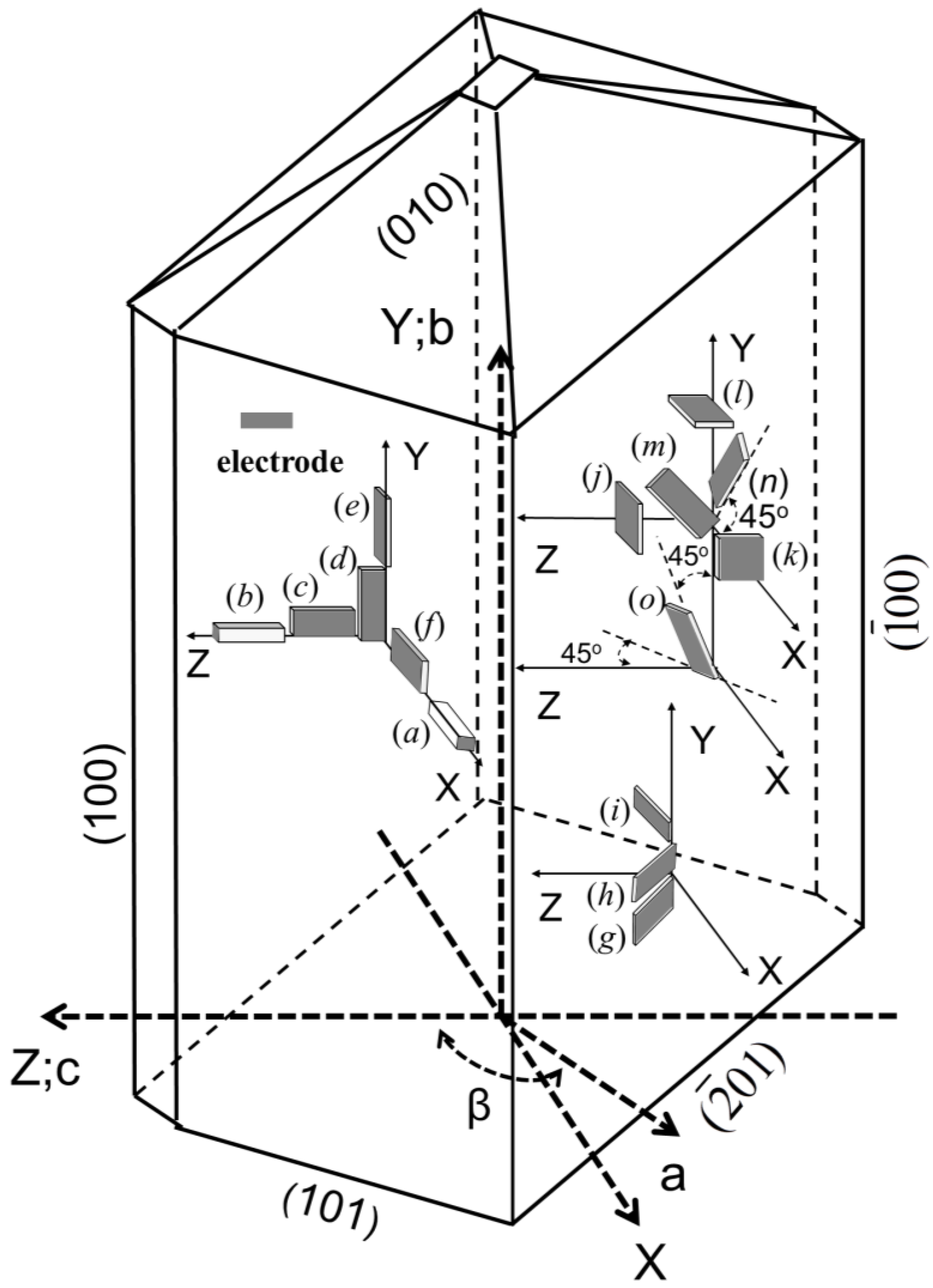
| Crystal Cuts | Modes | Material constants |
|---|---|---|
| X rod (a) | longitudinal extension | d11 |
| Z rod (b) | d33 | |
| ZX plate (f) | transverse extension | s11, d31, s22, d12, d32, s33, d13 |
| XY plate (d) | ||
| ZY plate (e) | ||
| XZ plate (c) | ||
| XZ plate (c) | width shear * | s44, d24 |
| ZX plate (f) | s66, d26 | |
| (XZw)45° (g) | s46 | |
| XZ plate (c) | thickness shear | s55, d15, d35 |
| ZX plate (f) | ||
| (XZw)45° (g) | transverse extension | s13, s15, s35 |
| (XZw)30° (h) | ||
| (XZw)−30° (i) | ||
| (XYt)45° (m) | transverse extension | s12, s23, s25 |
| (ZXt)45° (n) | ||
| (YZtw)45°/−45° (o) | ||
| X cut (k) | – | ε11, ε22, ε33, ε13 |
| Y cut (l) | ||
| Z cut (j) | ||
| (XZw)45° (g) |
4.2. Piezoelectric Coefficients and Elastic Compliances
4.2.1. Piezoelectric Coefficients d11 and d33


4.2.2. Piezoelectric Coefficients d12, d13, d31, and d32


4.2.3. Piezoelectric Coefficients d15, d35, d24, and d26


4.2.4. Elastic Compliances s12, s13, s15, s23, s25, s35 and s46


| Elastic Compliances sEij (pm2/N) | |||||||||||||
| Crystals | s11 | s12 | s13 | s15 | s22 | s23 | s25 | s33 | s35 | s44 | s46 | s55 | s66 |
| ErCOB | 7.3 | – | – | – | 6.7 | – | – | 8.9 | – | 31.2 | – | 21.6 | 16.6 |
| YCOB a | 7.2 | −0.8 | −2.47 | −0.4 | 7.0 | 0.55 | 0.54 | 8.9 | −0.12 | 34.5 | −0.37 | 21.0 | 16.3 |
| YCOB b | 7.15 | −0.35 | −2.8 | 0.74 | 6.91 | −0.68 | −0.46 | 8.79 | −1.2 | 35.0 | 3.5 | 23.0 | 15.0 |
| GdCOB b | 7.6 | −1.2 | −3.9 | 0.4 | 7.15 | −4.6 | −1.5 | 8.94 | 0.32 | 28.0 | 1.7 | 23.0 | 18.0 |
| GdCOB c | 7.6 | −0.92 | −0.95 | −0.99 | 7.1 | −0.92 | −14 | 8.9 | −0.33 | 17.0 | 14.0 | 19.0 | 18.0 |
| GdCOB | 7.6 | −1.0 | −1.0 | −0.4 | 7.3 | 1.2 | 2.8 | 8.9 | −0.6 | 31.7 | −0.9 | 20.0 | 18.0 |
| NdCOB d | 8.3 | −1.4 | −3.7 | 2.0 | 7.4 | −0.7 | 1.8 | 9.4 | −0.4 | 30.9 | 0.3 | 22.4 | 20.5 |
| NdCOB e | 8.3 | −2.0 | −3.5 | −0.9 | 7.5 | −1.6 | 0.5 | 9.4 | 0.9 | 34.0 | 1.0 | 22.0 | 20.0 |
| PrCOB | 9.0 | – | – | – | 7.9 | – | – | 10.4 | – | 33.9 | – | – | 18.7 |
| LaCOB f | 8.82 | −1.1 | −2.6 | 1.1 | 4.78 | −1.2 | 3.4 | 10.1 | −1.3 | 34.0 | 1.3 | 19.0 | 18.0 |
| Relative Dielectric Permittivities εTij/ε0 | |||||||||||||
| Crystals | ε11 | ε13 | ε22 | ε33 | |||||||||
| ErCOB | 9.5 | – | 11.8 | 10.0 | |||||||||
| YCOB a | 9.65 | 0.95 | 11.8 | 9.55 | |||||||||
| YCOB b | 9.57 | −0.96 | 11.4 | 9.52 | |||||||||
| GdCOB b | 10.5 | 0.8 | 14.0 | 10.4 | |||||||||
| GdCOB c | 9.03 | 0.75 | 12.35 | 10.25 | |||||||||
| GdCOB | 9.4 | 0.9 | 13.3 | 9.4 | |||||||||
| NdCOB d | 9.9 | −1.6 | 15.5 | 10.2 | |||||||||
| NdCOB e | 9.9 | −0.8 | 15.0 | 10.0 | |||||||||
| PrCOB | 9.8 | – | 15.3 | 10.1 | |||||||||
| LaCOB b | 9.87 | 1.2 | 14.3 | 9.87 | |||||||||
| LaCOB f | 9.87 | −1.24 | 14.9 | 9.87 | |||||||||
| Piezoelectric Coefficients dij (pC/N) | |||||||||||||
| Crystals | d11 | d12 | d13 | d15 | d24 | d26 | d31 | d32 | d33 | d35 | |||
| ErCOB | 1.7 | 3.4 | −4.3 | −1.4 | 3.9 | 7.6 | −0.7 | −2.8 | 1.5 | −5.5 | |||
| YCOB a | 1.7 | 3.9 | −4.2 | −1.1 | 4.4 | 7.9 | −0.77 | −2.5 | 1.4 | −5.0 | |||
| YCOB b | 1.4 | 3.8 | −4.2 | −7.2 | −2.6 | 8.0 | −0.22 | −2.3 | 0.83 | 2.2 | |||
| GdCOB b | 2.8 | 4.8 | −3.8 | −6.9 | 0.45 | 11 | −0.77 | −2.4 | 2.5 | −4 | |||
| GdCOB c | 2.4 | 4.0 | −4.5 | 0.66 | −2.8 | 2.4 | −1.1 | −2.2 | 2.0 | −2.7 | |||
| GdCOB | 2.4 | 4.1 | −4.7 | −2.2 | 5.1 | 11.1 | −1.1 | −2.5 | 2.0 | −3.8 | |||
| NdCOB d | 2.7 | 4.1 | −4.8 | 3.0 | 4.1 | 15.0 | −1.9 | −3.7 | 2.1 | 2.3 | |||
| NdCOB e | 1.7 | 3.9 | −4.9 | – | – | – | −1.4 | −2.5 | 1.5 | - | |||
| PrCOB | 2.5 * | 3.9 | −5.2 | −1.9 | 3.1 | 15.8 | −1.5 | −2.5 | 2.0 * | 3.3 | |||
| LaCOB | 2.4 * | 4.7 | – | – | 4.0 | 11.8 | – | – | 2.0 * | – | |||
| LaCOB b | 2.1 | 3.9 | −3.9 | – | – | – | −0.55 | −2.2 | 1.5 | – | |||
| LaCOB f | 1.28 | 3.89 | −3.89 | 0.62 | 6.41 | 8.73 | −0.55 | −2.22 | 1.10 | – | |||
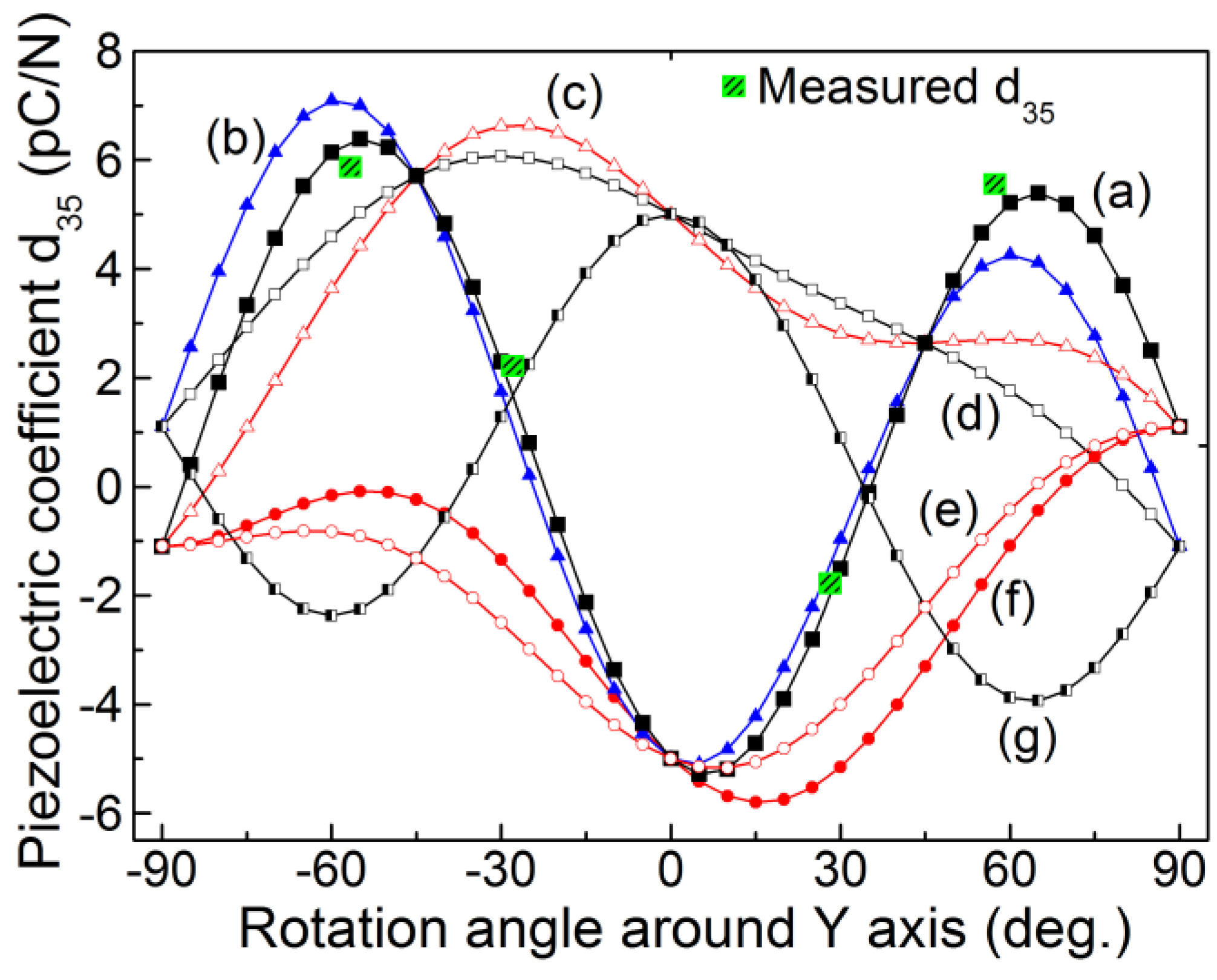
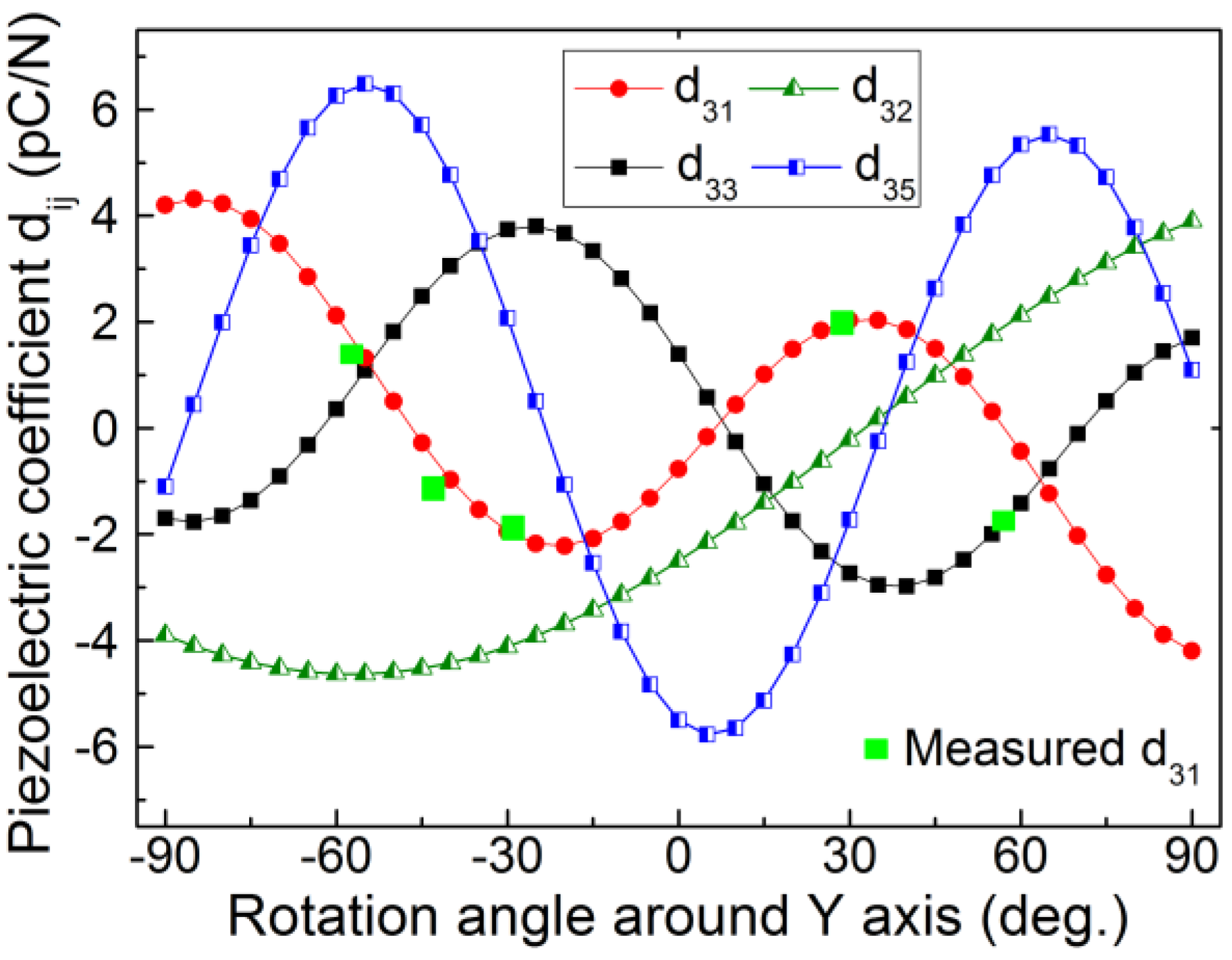
4.2.5. Determination of the Sign of the Piezoelectric Coefficients


 were determined by Equations (9)–(11), and the results were plotted in Figure 7. It is noted that the measured for different crystal cuts is in good agreement with the calculated results (Equation (20)).
5. The Investigation of Optimum Crystal Cuts
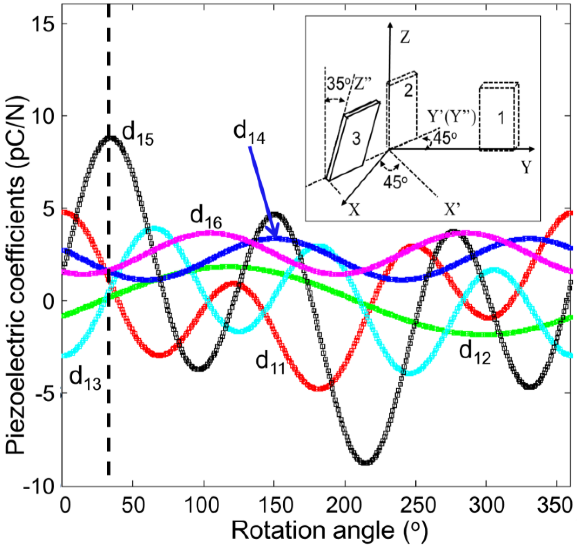
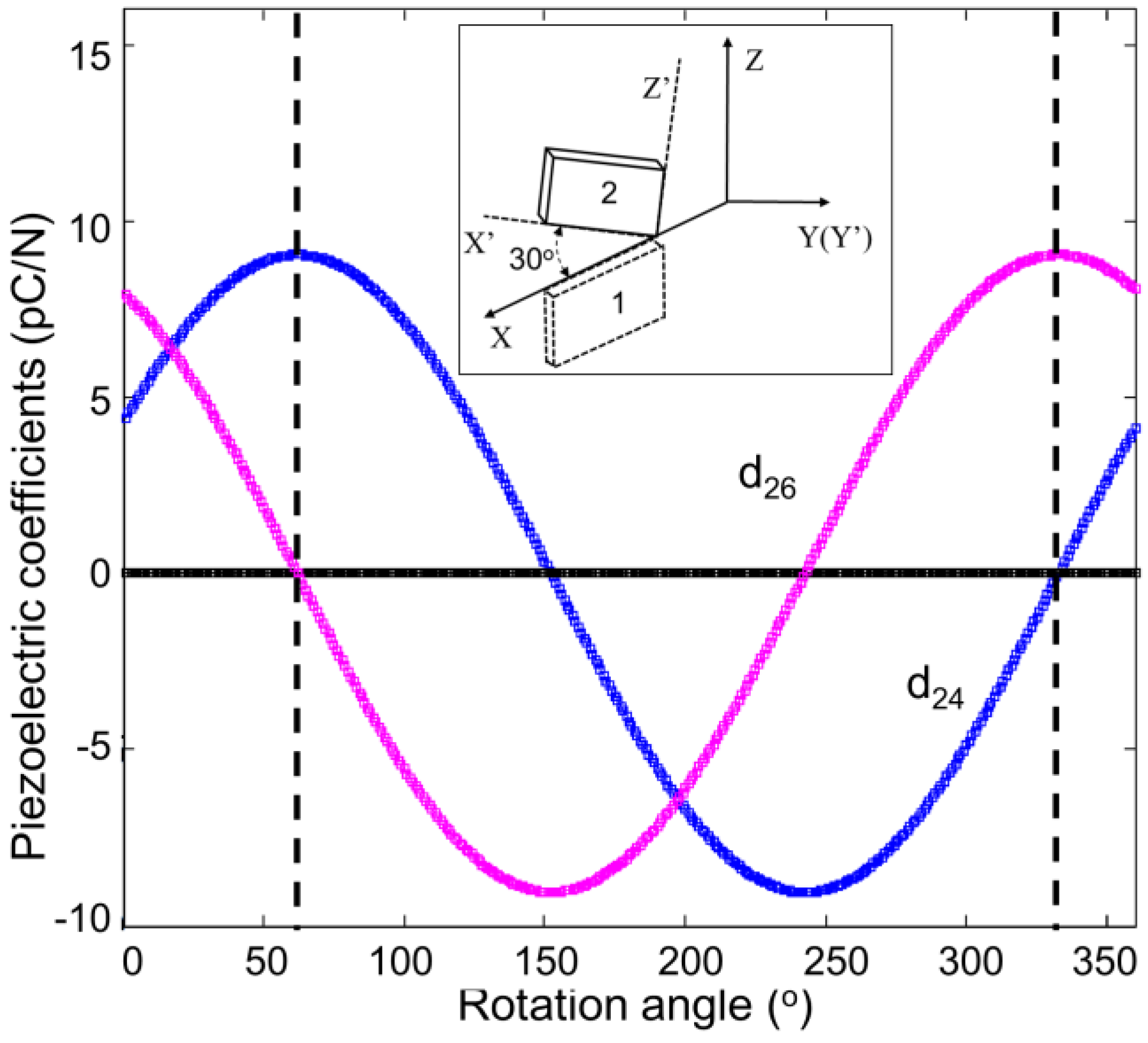
5.1. Rotated Crystal Cuts with Maximized Values
 ,
,  and
and  equal to d33, d35 and d24, respectively, when rotated around the Y-axis for ±90°. Meanwhile, when rotated around the X- and Z-axes for ±90°,
  and equal to d13 and d32, respectively.


| Crystals | d24 (pC/N) | d26 (pC/N) | Crystal Cuts | Maximum d26 (pC/N) |
|---|---|---|---|---|
| ErCOB | 3.9 | 7.6 | (YXt)-25° | ~8.5 |
| YCOB | 4.4 | 7.9 | (YXt)-30° | ~9.0 |
| GdCOB | 4.7 | 11.5 | (YXt)-20° | ~12.0 |
| SmCOB | 4.1 | 12.7 | (YXt)-20° | ~13.3 |
| NdCOB | 4.1 | 15.0 | (YXt)-15° | ~15.5 |
| PrCOB | 3.1 | 15.8 | (YXt)-10° | ~16.1 |
| LaCOB | 4.0 | 11.8 | (YXt)-20° | ~12.4 |
5.2. Rotated Crystal Cuts without Piezoelectric Cross-Talk


6. Summary and Future Research
6.1. Significance of ReCOB Crystals
6.2. Future Research
Acknowledgments
Author Contributions
Conflicts of Interest
References
- Zhang, S.J.; Yu, F.P. Piezoelectric materials for high temperature sensors. J. Am. Ceram. Soc. 2011, 94, 3153–3170. [Google Scholar] [CrossRef]
- Zhang, S.J.; Jiang, X.N.; Lapsley, M.; Moses, P.; Shrout, T.R. Piezoelectric accelerometers for ultrahigh temperature application. Appl. Phys. Lett. 2010, 96. [Google Scholar] [CrossRef]
- Zhang, S.J.; Frantz, E.; Xia, R.; Everson, W.; Randi, J.; Snyder, D.W.; Shrout, T.R. Gadolinium calcium oxyborate piezoelectric single crystals for ultrahigh temperature (>1000 °C) applications. J. Appl. Phys. 2008, 104. [Google Scholar] [CrossRef]
- Jiang, X.N.; Kim, K.; Zhang, S.J.; Johnson, J.; Sakazar, G. High-temperature piezoelectric sensing. Sensors 2014, 14, 144–169. [Google Scholar]
- Shrout, T.R.; Eitel, R.; Randall, R.A. High performance, high temperature perovskite piezoelectric ceramics. In Piezoelectric Materials in Devices; EPFL Swiss Federal Institute of Technology: Lausanne, Switzerland, 2002. [Google Scholar]
- Fritze, H.; Schneider, O.; She, H.; Tuller, H.L.; Borchardt, G. High temperature bulk acoustic wave properties of langasite. Phys. Chem. Chem. Phys. 2003, 5, 5207–5214. [Google Scholar] [CrossRef]
- Zhang, S.J.; Zheng, Y.Q.; Kong, H.K.; Xin, J.; Frantz, E.; Shrout, T.R. Characterization of high temperature piezoelectric crystals with an ordered langasite structure. J. Appl. Phys. 2009, 105. [Google Scholar] [CrossRef]
- Yu, F.P.; Zhao, X.; Pan, L.H.; Yuan, D.R.; Zhang, S.J. Investigation of zero temperature compensated cuts in langasite-type piezocrystals for high temperature applications. J. Phys. D Appl. Phys. 2010, 43. [Google Scholar] [CrossRef]
- Hornsteiner, J.; Born, E.; Riha, E. Langasite for high temperature surface acoustic wave applications. Phys. Status Solidi A 1997, 163, R3–R4. [Google Scholar] [CrossRef]
- Sauerwald, J.; Richter, D.; Ansorge, E.; Schmidt, B.; Fritze, H. Langasite based miniaturized functional structures: Preparation, high-temperature properties and applications. Phys. Status Solidi A 2011, 208, 390–403. [Google Scholar]
- Yu, F.P.; Zhang, S.J.; Zhao, X.; Yuan, D.R.; Qin, L.F.; Wang, Q.M.; Shrout, T.R. Investigation of Ca3TaGa3Si2O14 piezoelectric crystals for high temperature sensors. J. Appl. Phys. 2011, 109. [Google Scholar] [CrossRef]
- Xin, J.; Zheng, Y.Q.; Kong, H.K.; Chen, H.; Tu, X.N.; Shi, E.W. Growth of a new ordered langasite structure crystal Ca3TaAl3Si2O14. Cryst. Growth Des. 2008, 8, 2617–2619. [Google Scholar]
- Fritze, H. High-temerature bulk acoustic wave sensors. Meas. Sci. Technol. 2011, 22. [Google Scholar] [CrossRef]
- Fritze, H. High-temerature piezoelectric crystals and devices. J. Electroceram. 2011, 26, 122–161. [Google Scholar] [CrossRef]
- Li, J.; Liang, X.M.; Xu, G.G.; Zhao, H.Y.; Wang, J.Y. Flux growth of GaPO4 crystal. Piezoelectr. Acoustrooptocs. 2007, 29, 695–696. [Google Scholar]
- Philippot, E.; Ibanez, A.; Goiffon, A.; Cochez, M.; Zarka, A.; Capelle, B.; Schwartzel, J.; Détaint, J. A quartz-like material: Gallium phosphate (GaPO4): Crystal growth and characterization. J. Cryst. Growth 1993, 130, 195–208. [Google Scholar] [CrossRef]
- Millichamp, J.; Ali, E.; Brandon, N.P.; Brown, R.J.C.; Hodgson, D.; Kalyvas, C.; Manos, G.; Brett, D.J.L. Application of a GaPO4 crystal microbalance for the detection of coke formation in high-temperature reactors and solid oxide fuel cells. Ind. Eng. Chem. Res. 2011, 50, 8371–8375. [Google Scholar] [CrossRef]
- Schiopu, P.; Cristea, I.; Grosu, N.; Cracium, A. Development of SAW filters based on GaPO4. In Proceedings of the 2011 IEEE 17th International Symposium for Design and Technology in Electronic Packaging (SIITME), Timisoara, Romania, 20–23 October 2011.
- Traon, O.L.; Masson, S.; Chartier, C.; Janiaud, D. LGS and GaPO4 piezoelectric crystals: New results. Solid State Sci. 2010, 12, 318–324. [Google Scholar] [CrossRef]
- Zhang, Y.Y.; Zhang, H.J.; Yu, H.H.; Sun, S.Q.; Wang, J.Y.; Jiang, M.H. Characterization of disordered melilite Nd:SrLaGa3O7 crystal. IEEE J. Quantum Electron. 2011, 47, 1506–1513. [Google Scholar] [CrossRef]
- Hagiwara, M.; Noguchi, H.; Hoshina, T.; Takeda, H.; Fujihara, S.; Kodama, N.; Tsurumi, T. Growth and characterization of Ca2Al2SiO7 piezoelectric single crystals for high temperature sensor applications. Jpn. J. Appl. Phys. 2013, 52. [Google Scholar] [CrossRef]
- Takeda, H.; Hagiwara, M.; Noguchi, H.; Hoshina, T.; Takahashi, T.; Kodama, N.; Tsurumi, T. Calcium aluminate silicate Ca2Al2SiO7 single crystal applicable to piezoelectric sensors at high temperature. Appl. Phys. Lett. 2013, 102. [Google Scholar] [CrossRef]
- Shen, C.; Wang, J.Y.; Zhang, H.J.; Yin, X.; Zhang, Y.Y.; Xu, H.H.; Han, S.J. Growth and determination of electro-elastic constants of Ba2TiSi2O8 crystal. J. Chin. Ceram. Soc. 2012, 40, 1311–1315. [Google Scholar]
- Kimura, M.; Fujino, Y.; Kawanura, T. New piezoelectric crystals: Synthetic fresnoite (Ba2Si2TiO8). Appl. Phys. Lett. 1976, 29, 227–228. [Google Scholar] [CrossRef]
- Halliyal, A.; Bhalla, A.S.; Markgraf, S.A.; Cross, L.E.; Newnham, R.E. Unusual pyroelectric and piezoelectric properties of fresoite (Ba2TiSi2O8) single crystal and polar glass-ceramics. Ferroelectrics 1985, 62, 27–38. [Google Scholar] [CrossRef]
- Kimura, M. Elastic and piezoelectric properties of Ba2Si2TiO8. J. Appl. Phys. 1977, 48, 2850–2856. [Google Scholar] [CrossRef]
- Mockel, R.; Reuther, C.; Gotze, J. REECOB: 20 years of rare earth element calcium oxoborates crystal growth research. J. Cryst. Growth 2013, 371, 70–76. [Google Scholar] [CrossRef]
- Furuya, H.; Yoshimura, M.; Kobayashi, T.; Murase, K.; Mori, Y.; Sasaki, T. Crystal growth and characterization of GdxY1−xCa4O(BO3)3 crystal. J. Cryst. Growth 1999, 198–199, 560–563. [Google Scholar] [CrossRef]
- Zhang, S.J.; Cheng, Z.X.; Lu, J.H.; Li, G.M.; Lu, J.R.; Shao, Z.S.; Chen, H.C. Studies on the effective nonlinear coefficient of GdCa4O(BO3)3 crystal. J. Cryst. Growth 1999, 205, 453–456. [Google Scholar] [CrossRef]
- Zhang, S.J.; Cheng, Z.X.; Zhang, S.J.; Han, J.R.; Sun, L.K.; Chen, H.C. Growth and noncritical phase-matching third-harmonic-generation of GdxY1−xCa4O(BO3)3 crystal. J. Cryst. Growth 2000, 213, 415–418. [Google Scholar] [CrossRef]
- Zhang, H.J.; Jiang, H.D.; Wang, J.Y.; Hu, X.B.; Yu, G.W.; Yu, W.T.; Gao, L.; Liu, J.A.; Zhang, S.J.; Jiang, M.H. Growth and characterization of a LaCa4O(BO3)3 crystal. Appl. Phys. A Mater. Sci. Proc. 2004, 78, 889–893. [Google Scholar] [CrossRef]
- Adams, J.J.; Ebbers, C.A.; Schaffers, K.I.; Payne, S.A. Nonlinear optical properties of LaCa4O(BO3)3. Opt. Lett. 2001, 26, 217–219. [Google Scholar] [CrossRef]
- Aka, G.; Kahn-Harari, A.; Mougel, F.; Vivien, D.; Salin, F.; Coquelin, P.; Colin, P.; Pelenc, D.; Damelet, J.P. Linear- and nonlinear-optical properties of a new gadolinium calcium oxoborate crystal, Ca4GdO(BO3)3. J. Opt. Soc. Am. B 1997, 14, 2238–2247. [Google Scholar] [CrossRef]
- Yu, F.P.; Zhang, S.J.; Zhao, X.; Guo, S.Y.; Duan, X.L.; Yuan, D.R.; Shrout, T.R. Investigation of the dielectric and piezoelectric properties of ReCa4O(BO3)3 crystals. J. Phys. D Appl. Phys. [CrossRef]
- Kim, K.; Zhang, S.J.; Huang, W.B.; Yu, F.P.; Jiang, X.N. YCa4O(BO3)3 (YCOB) high temperature vibration sensor. J. Appl. Phys. 2011, 109. [Google Scholar] [CrossRef]
- Sotnikov, A.; Schmidt, H.; Weihnacht, M.; Zhang, S.J.; Shrout, T.R.; Yu, F.P. Elastic constants of YCa4O(BO3)3 and NdCa4O(BO3)3 single crystals by the pulse-echo ultrasonic method. In Proceedings of the 2012 IEEE International Ultrasonics Symposium (IUS), Dresden, Germany, 7–10 October 2012.
- Nakao, H.; Nishida, M.; Shikida, T.; Shimizu, H.; Takeda, H.; Shiosaki, T. Growth and SAW properties of rare-earth calcium oxoborate crystals. J. Alloys Compd. 2006, 408–412, 582–585. [Google Scholar]
- Yu, F.P.; Zhang, S.J.; Cheng, X.F.; Duan, X.L.; Ma, T.F.; Zhao, X. Crystal growth, structure and thermal properties of noncentrosymmetric single crystals PrCa4O(BO3)3. CrystEng Comm 2013, 15, 5226–5231. [Google Scholar] [CrossRef]
- Shimamura, K.; Takeda, H.; Kohnp, T.; Fukuda, T. Growth and characterization of lanthanum gallium silicate La3Ga5SiO14 single crystals for piezoelectric applications. J. Cryst. Growth 1997, 163, 388–392. [Google Scholar] [CrossRef]
- Wang, Z.M.; Yuan, D.R.; Cheng, Z.X.; Duan, X.L.; Sun, H.Q.; Shi, X.Z.; Wei, X.C.; Lü, Y.Q.; Xu, D.; Lü, M.K.; et al. Growth of a new ordered langasite structure compound Ca3TaGa3Si2O14 single crystal. J. Cryst. Growth 2003, 253, 398–403. [Google Scholar] [CrossRef]
- Armand, P.; Beaurain, M.; Ruffle, B.; Menaert, B.; Balitsky, D.; Clement, S.; Papet, P. Characterizations of piezoelectric GaPO4 single crystals grown by the flux method. J. Cryst. Growth 2008, 310, 1455–1459. [Google Scholar] [CrossRef]
- Warner, A.W.; Onoe, M.; Coquin, G.A. Determine elastic piezoelectric and dielectric properties of class 3m. J. Acoust. Soc. Am. 1967, 42, 1223–1231. [Google Scholar] [CrossRef]
- Terentiev, A.V.; Prokoshin, P.V.; Yumashev, K.V.; Mikhailov, V.P.; Ryba-Romanowski, W.; Golab, S.; Pisarski, W. Passive mode locking of a Nd3+:SrLaGa3O7 laser. Appl. Phys. Lett. 1995, 67, 2442–2444. [Google Scholar] [CrossRef]
- Zhang, Y.Y.; Yin, X.; Yu, H.H.; Cong, H.J.; Zhang, H.J.; Wang, J.Y.; Boughton, R.I. Growth and piezoelectric properties of melilite ABC3O7 crystals. Cryst. Growth Des. 2012, 12, 622–628. [Google Scholar] [CrossRef]
- Liu, Y.Q.; Wei, L.; Yu, F.P.; Wang, Z.P.; Zhao, Y.G.; Han, S.; Zhao, X.; Xu, X.G. Crystal growth and efficient second-harmonicgeneration of the monoclinic LaCa4O(BO3)3 crystal. CrystEng Comm 2013, 15, 6035–6039. [Google Scholar]
- Pan, Z.B.; Zhang, H.J.; Yu, H.H.; Wang, J.Y. Czochralski growth of large aperture YCOB crystal. J. Chin. Ceram. Soc. 2013, 41, 55–57. [Google Scholar]
- Ilyukhin, A.B.; Dzhurinskii, B.F. Crystal structures of binary oxoborates LnCa4O(BO3)3 (Ln = Gd, Tb, and Lu) and Eu2CaO(BO3)2. Russ. J. Inorg. Chem. 1993, 38, 917–920. [Google Scholar]
- Wu, A.H.; Jiang, L.W.; Qian, G.X.; Zheng, Y.Q.; Xu, J.; Shi, E.W. Bridgman growth of large-aperture yttrium calcium oxyborate crystal. Mater. Res. Bull. 2012, 47, 2689–2691. [Google Scholar] [CrossRef]
- Aka, G.; Kahn-Harari, A.; Vivien, D.; Benitez, J.M.; Salin, F.; Godard, J. A new nonlinear and neodymium laser self-frequency doubling crystal with congruent melting Ca4GdO(BO3)3, (GdCOB). Eur. J. Solid State Inorg. Chem. 1996, 33, 723–736. [Google Scholar]
- Luo, J.; Fan, S.J.; Xie, H.Q.; Xiao, K.C.; Qian, S.X.; Zhong, Z.W.; Qian, G.X.; Sun, R.Y.; Xu, J.Y. Thermal and nonlinear optical properties of Ca4YO(BO3)3. Cryst. Res. Technol. 2001, 36, 1215–1221. [Google Scholar] [CrossRef]
- Yu, F.P.; Duan, X.L.; Zhang, S.J.; Yu, Y.G.; Ma, T.F.; Zhao, X. Temperature dependence of electro-elastic properties of yttrium calcium oxyborate single crystals. In Proceedings of the 2012 Symposium on Piezoelectricity, Acoustic Waves and Device Applications, Shanghai, China, 23–25 November 2012.
- Zheng, Y.Q.; Wu, A.H.; Gao, P.; Tu, X.N.; Liang, X.Y.; Hou, J.; Yang, L.M.; Wang, T.; Qian, L.J.; Shi, E.W. Laser damage threshold and nonlinear optical properties of large aperture elements of YCOB crystal. In Proceedings of Pacific Rim Laser Damage 2011: Optical Materials for High Power Lasers, Shanghai, China, 12 January 2012.
- Fei, Y.T.; Chai, B.H.T.; Ebbers, C.A.; Liao, Z.M.; Schaffers, K.I.; Thelin, P. Large-aperture YCOB crystal growth for frequency conversion in the high average power laser system. J. Cryst. Growth 2006, 290, 301–306. [Google Scholar] [CrossRef]
- IEEE Standard on Piezoelectricity; ANSI/IEEE Standard; IEEE: New York, NY, USA, 1987.
- Liu, Y.Q.; Yu, F.P.; Wang, Z.P.; Hou, S.; Yang, L.; Xu, X.G.; Zhao, X. Bulk growth and nonlinear optical properties of thulium calcium oxyborate single crystals. CrystEng Comm 2014. [Google Scholar] [CrossRef]
- Yuan, D.S.; Jia, Z.T.; Wang, J.; Gao, Z.L.; Zhang, J.J.; Fu, X.W.; Shu, J.; Yin, Y.R.; Hu, Q.Q.; Tao, X.T. Bulk growth, structure, and characterization of the new monoclinic TbCa4O(BO3)3 crystal. CrystEngComm 2014, 16, 4008–4015. [Google Scholar] [CrossRef]
- Yu, F.P.; Hou, S.; Zhang, S.J.; Lu, Q.M.; Zhao, X. Electro-elastic properties of YCa4O(BO3)3 piezoelectric crystals. Phys. Status Solidi A 2014, 211, 574–579. [Google Scholar] [CrossRef]
- Shimizu, H.; Nishida, T.; Takeda, H.; Shiosaki, T. Dielectric, elastic and piezoelectric properties of RCa4O(BO3)3 (R = rare-earth elements) crystals with monoclinic structure of point group m. J. Cryst. Growth 2009, 311, 916–920. [Google Scholar] [CrossRef]
- Pawlaczyk, C.; Markiewiz, E.; Kłos, A.; Hofman, W.; Pajaczkowska, A. Elastic and piezoelectric properties of gadolinium calcium oxoborate GdCa4O(BO3)3 crystal. Phys. Status Solidi A 2006, 203, 2103–2118. [Google Scholar]
- Yu, F.P.; Zhang, S.J.; Zhao, X.; Yuan, D.R.; Wang, C.M.; Shrout, T.R. Characterization of neodymium calcium oxyborate piezoelectric crystal with monoclinic phase. Cryst. Growth Des. 2010, 10, 1871–1877. [Google Scholar] [CrossRef]
- Karaki, T.; Adachi, M.; Kuniyoshi, Y. Evaluation of material constants in NdCa4O(BO3)3 piezoelectric single crystal. J. Electroceram. 2008, 21, 823–826. [Google Scholar] [CrossRef]
- Shimizu, H.; Kodama, K.; Takeda, H.; Nishida, T.; Shikida, T.; Okamura, S.; Shiosaki, T. Evaluation of material constants and temperature properties in lanthanum calcium oxoborate LaCa4O(BO3)3 single crystals. Jpn. J. Appl. Phys. 2004, 43, 6716–6720. [Google Scholar] [CrossRef]
- Yu, F.P.; Zhang, S.J.; Zhao, X.; Yuan, D.R.; Wang, Q.M.; Shrout, T.R. High temperature piezoelectric properties of yttrium calcium oxyborate single crystals. Phys. Status Solidi R 2010, 4, 103–105. [Google Scholar]
- Gautschi, G. Piezoelectric Sensorics: Force, Strain, Pressure, Acceleration and Acoustic Emission Sensors, Materials and Amplifiers, 2nd ed.; Springer-Verlag: Berlin, Germany, 2002. [Google Scholar]
© 2014 by the authors; licensee MDPI, Basel, Switzerland. This article is an open access article distributed under the terms and conditions of the Creative Commons Attribution license (http://creativecommons.org/licenses/by/3.0/).
Share and Cite
Yu, F.; Duan, X.; Zhang, S.; Lu, Q.; Zhao, X. Rare-Earth Calcium Oxyborate Piezoelectric Crystals ReCa4O(BO3)3: Growth and Piezoelectric Characterizations. Crystals 2014, 4, 241-261. https://doi.org/10.3390/cryst4030241
Yu F, Duan X, Zhang S, Lu Q, Zhao X. Rare-Earth Calcium Oxyborate Piezoelectric Crystals ReCa4O(BO3)3: Growth and Piezoelectric Characterizations. Crystals. 2014; 4(3):241-261. https://doi.org/10.3390/cryst4030241
Chicago/Turabian StyleYu, Fapeng, Xiulan Duan, Shujun Zhang, Qingming Lu, and Xian Zhao. 2014. "Rare-Earth Calcium Oxyborate Piezoelectric Crystals ReCa4O(BO3)3: Growth and Piezoelectric Characterizations" Crystals 4, no. 3: 241-261. https://doi.org/10.3390/cryst4030241