Article

Pb(In1/2Nb1/2)O3–Pb(Mg1/3Nb2/3)O3–PbTiO3 Piezoelectric Single-Crystal Rectangular Beams: Mode-Coupling Effect and Its Application to Ultrasonic Array Transducers

1
Department of Electrical Engineering, The Hong Kong Polytechnic University, Hung Hom, Kowloon, Hong Kong
2
Key Laboratory of Inorganic Functional Material and Device, Shanghai Institute of Ceramics, Chinese Academy of Sciences, Shanghai 201800, China
*
Author to whom correspondence should be addressed.
Crystals 2017, 7(4), 101; https://doi.org/10.3390/cryst7040101
Submission received: 6 February 2017 / Revised: 17 March 2017 / Accepted: 23 March 2017 / Published: 2 April 2017
(This article belongs to the Special Issue Crystal Growth for Optoelectronic and Piezoelectric Applications)

Abstract

:
Pb(In1/2Nb1/2)O3–Pb(Mg1/3Nb2/3)O3–PbTiO3 (PIN–PMN–PT) piezoelectric single-crystal rectangular beams with the PIN:PMN:PT ratio of 0.33:0.35:0.32 are prepared, and their mode-coupling effect is investigated both theoretically and experimentally for ultrasonic array transducer applications. The PIN–PMN–PT rectangular beams become a tall-narrow beam and a short-wide plate, and so exhibiting an uncoupled height-extensional (beam) mode and an uncoupled thickness-extensional (plate) mode, at a width-to-height ratio G (= L/H) of <0.7 and >6.0, respectively. With G varying in the range of 1.6 to 3.1, the beam mode not only couples strongly with the width (lateral) mode, but also coexists obviously with the plate mode, giving high electromechanical coupling coefficients k’33 and kt of ~0.75 and ~0.50, respectively. With the guide of the mode-coupling results, a multifrequency ultrasonic array transducer having three distinct operational frequencies of 1.52, 2.60, and 6.01 MHz, corresponding to the coupled/coexistent beam mode, lateral mode, and plate mode, respectively, is developed using a mode-coupled rectangular beam of G = 1.6. Two different single-frequency ultrasonic array transducers, fabricated using two different uncoupled rectangular beams, one operating in uncoupled beam mode with G = 0.6 at 2.24 MHz and one working in uncoupled plate mode with G = 10.0 at 5.75 MHz, are also developed for comparison.

1. Introduction

Longitudinal wave ultrasonic transducers are widely used in medical ultrasonic imaging, nondestructive evaluation, underwater sonar, and so on. Piezoelectric materials are generally chosen as the transduction elements to generate and receive longitudinal waves at the ultrasonic frequencies of interest. This, in turn, requires the piezoelectric transduction elements to work in a longitudinal resonance mode. Accordingly, the length-extensional mode in a piezoelectric bar (i.e., the bar mode), the thickness-extensional mode in a piezoelectric plate/disk (i.e., the plate/disk mode), and the height-extensional mode in a piezoelectric beam (i.e., the beam mode) are the three main types of longitudinal resonance modes commonly used in piezoelectric ceramic–polymer 1–3 composite ultrasonic transducers, single-element ultrasonic transducers, and ultrasonic array transducers, respectively [1,2,3].
Ultrasonic array transducers based on piezoelectric rectangular beams have been playing an important role in modern medical ultrasonic imaging systems. In particular, the uncoupled beam mode in the piezoelectric rectangular beams has been utilized to facilitate high sensitivity and wide bandwidth in single-frequency ultrasonic array transducers [4,5]. Recently, multifrequency ultrasonic array transducers have attracted a special attention to incorporate a low transmitting frequency with a high receiving frequency for simultaneously satisfying deep penetration and high resolution in a single transducer [3]. As the width-to-height ratio G (= L/H) of the piezoelectric rectangular beams has the determinative effect on their ultimate shape and hence the resulting uncoupled/coupled modes and frequencies, it is physically interesting and technologically important to study the mode-coupling effect in the piezoelectric rectangular beams as well as its application to the design and control of preferred operational modes and frequencies in the ultrasonic array transducers.
Pb(Zr1−xTix) (PZT) piezoelectric ceramics are the traditional candidates for ultrasonic transducers. Relaxor ferroelectric solid-solution single crystals near the morphotropic phase boundary (MPB) have been researched widely over the past decade because of their superior piezoelectric properties in comparison with those of the PZT ceramics. Among them, binary relaxor-based Pb(Mg1/3Nb2/3)O3–PbTiO3 (PMN–PT) single crystals are regarded as one of the most representative types and have received much interest in ultrasonic transducer applications over the past two decades [6,7,8]. More recently, ternary relaxor-based Pb(In1/2Nb1/2)O3–Pb(Mg1/3Nb2/3)O3–PbTiO3 (PIN–PMN–PT) single crystals, especially for those with the PIN:PMN:PT ratio of 0.33:0.35:0.32, have been synthesized and evaluated to show similarly strong piezoelectric properties as well as significantly higher MPB temperature, Curie temperature, and coercive field when compared with the PMN–PT single crystals [9,10,11,12,13].
In order to extend the potential application of the PIN–PMN–PT single crystals to ultrasonic array transducers, in this paper we prepare PIN–PMN–PT single-crystal rectangular beams with 0.33:0.35:0.32 PIN:PMN:PT ratio and investigate theoretically and experimentally their mode-coupling effect by changing their L and hence G value. Based on the results of mode coupling, a multifrequency ultrasonic array transducer is developed using a mode-coupled rectangular beam of G = 1.6 to excite three coupled/coexistent operational modes, namely beam mode, lateral mode, and plate mode, at three different operational frequencies of 1.52, 2.60, and 6.01 MHz, respectively. The performance of the multifrequency ultrasonic array transducer is evaluated and compared with those of two different single-frequency ultrasonic array transducers having two different uncoupled rectangular beams to respectively enable an uncoupled beam mode with G = 0.6 at 2.24 MHz and an uncoupled plate mode with G = 10.0 at 5.75 MHz.

2. Results and Discussion

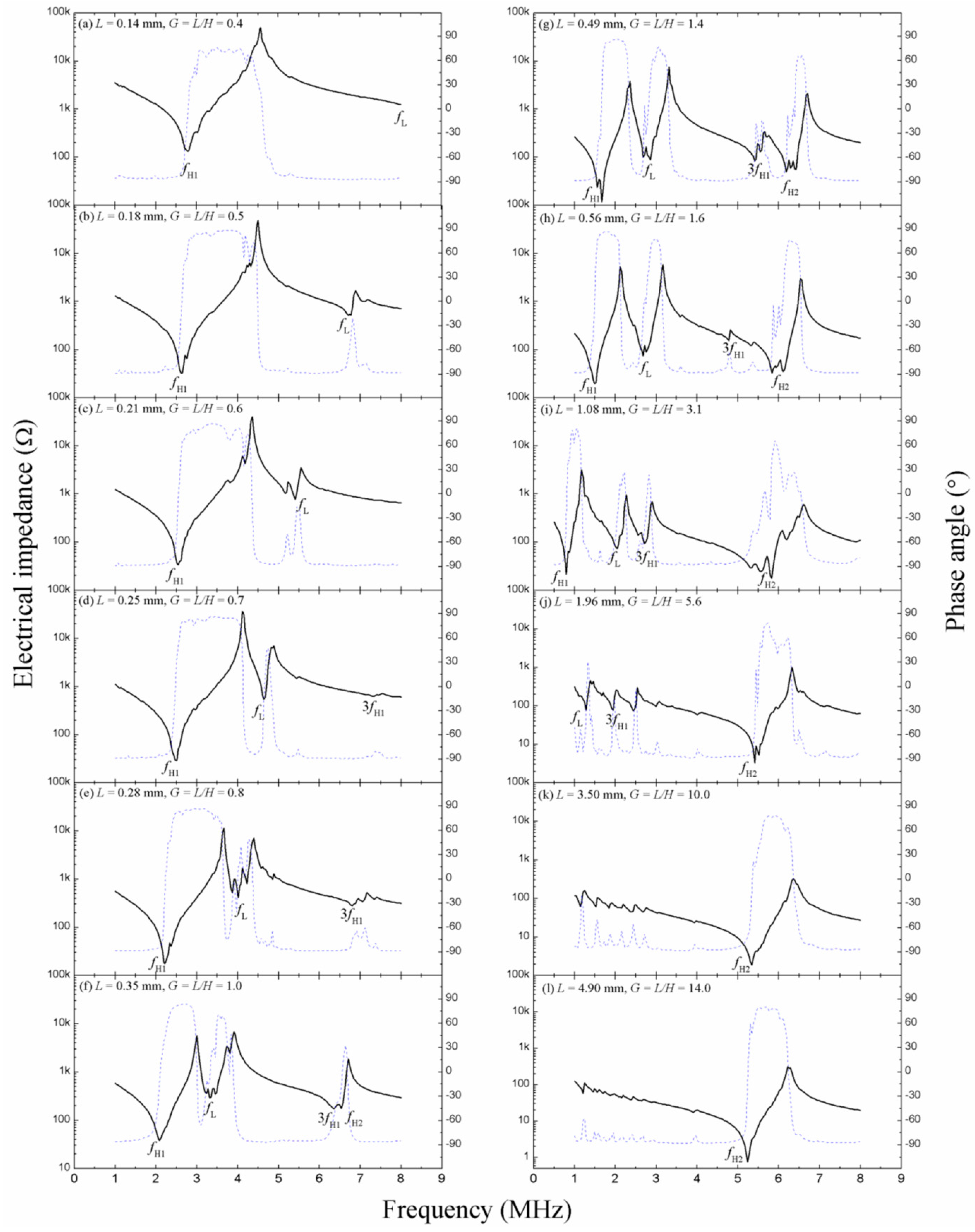
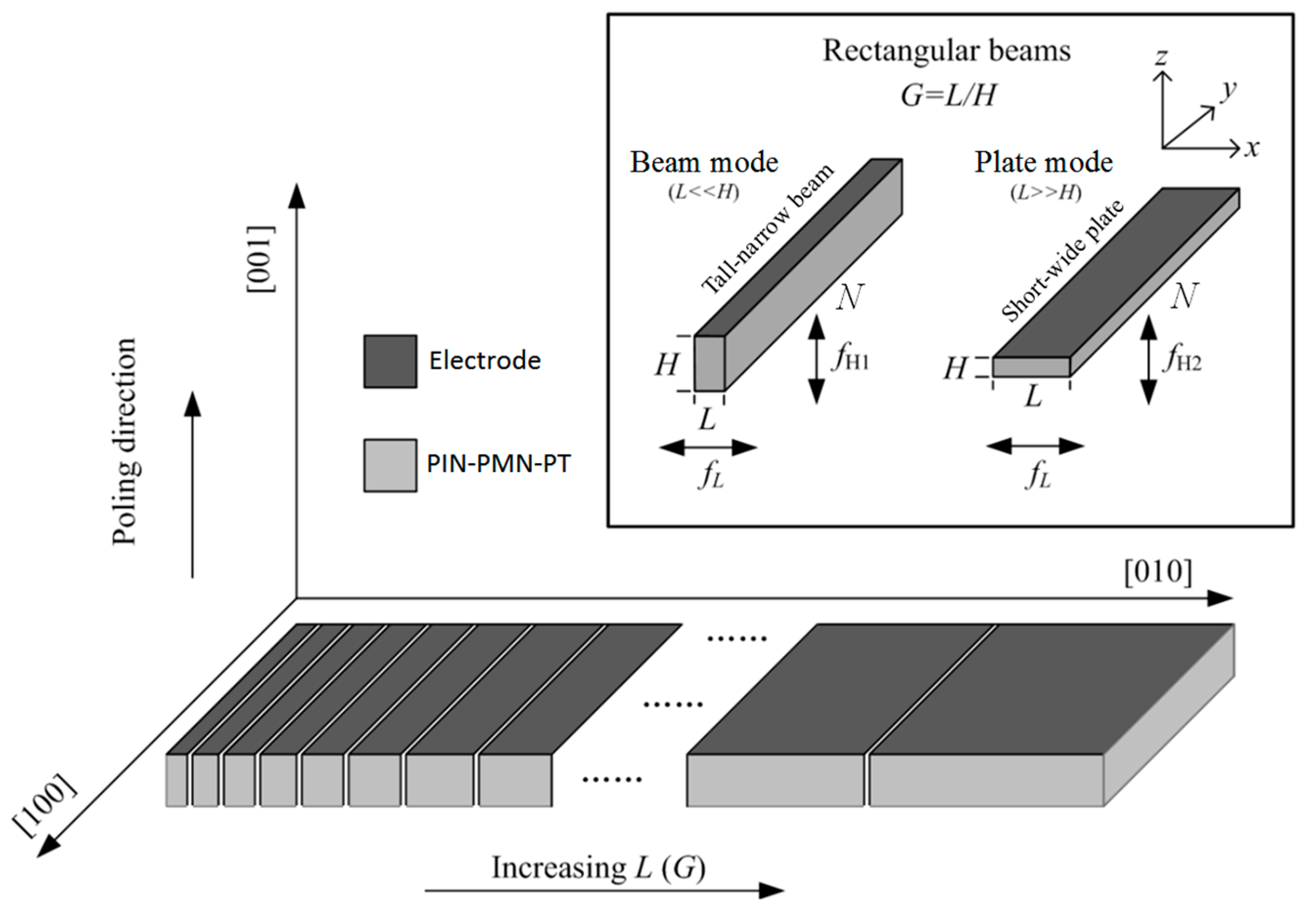
2.1. Mode Coupling Effect in PIN–PMN–PT Rectangular Beams

Figure 1 illustrates the crystallographic orientation and poling direction of an as-prepared PIN–PMN–PT rectangular plate with 0.33:0.35:0.32 PIN:PMN:PT ratio, together with its rectangular beams having the same length N (=13.0 mm) and height H (=0.35 mm) but with different widths L (=0.14–4.90 mm) and hence different width-to-height ratios G (=L/H = 0.4–14.0). Each rectangular beam has its L, N, and H aligned along the x-, y-, and z-axes, respectively, as well as its poling direction oriented in the [001] direction along the z-axis. Details of the preparation of the [001]-poled PIN–PMN–PT rectangular plate and its [001]-poled rectangular beams are provided in Section 3.1. These rectangular beams are very long (i.e., N >> L and H) so that the operational modes in the megahertz frequency range are mainly determined by the dimensions (i.e., L and H) of the rectangular cross-section and can be classified into three main types as follows.
(1)
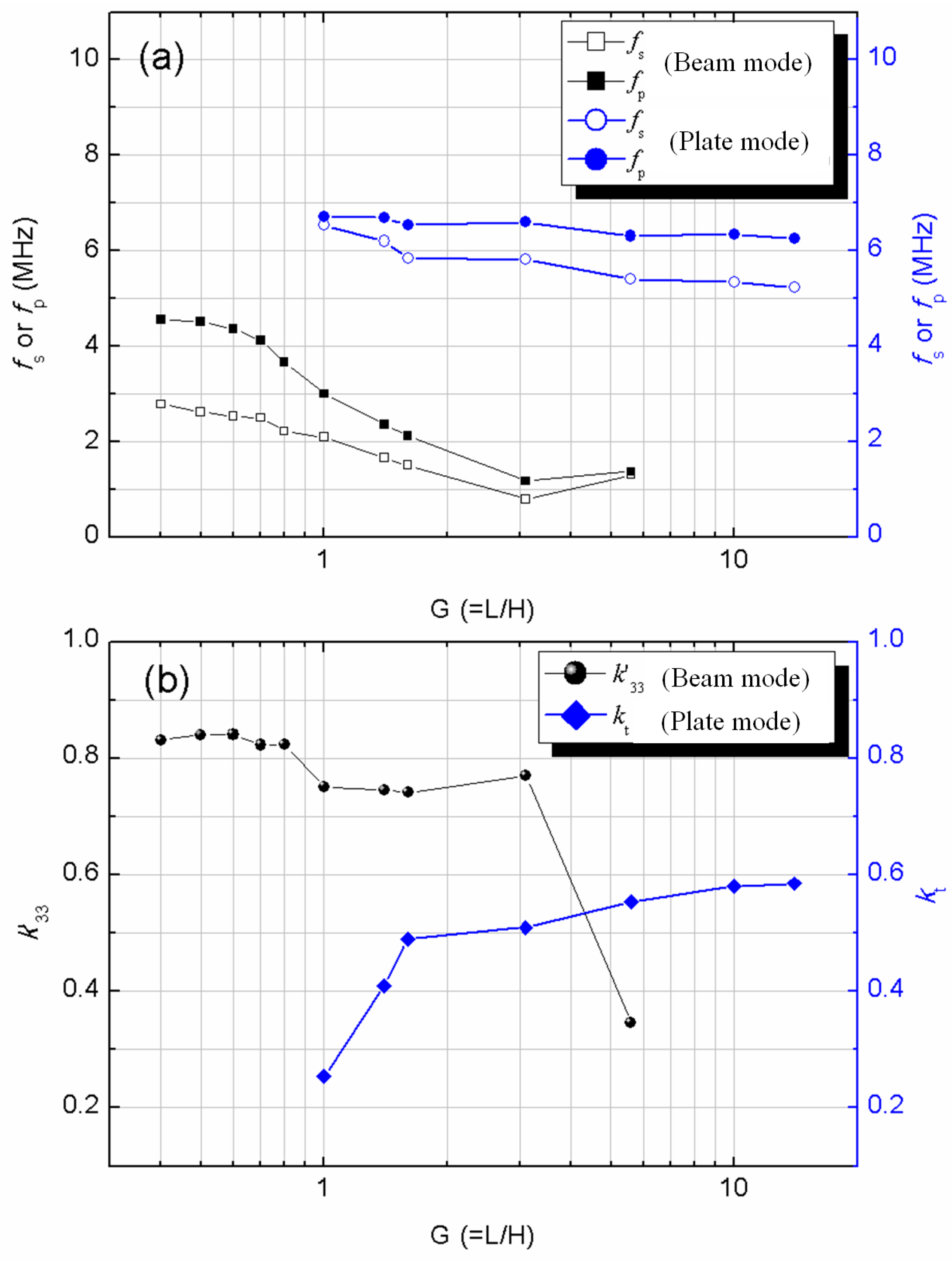
The height-extensional (beam) mode. When L << H such that G is small, the PIN–PMN–PT rectangular beams become tall-narrow beams and operate in beam mode. The beam mode frequency fH1 is essentially determined by the height H of the PIN–PMN–PT rectangular beams.
(2)
The thickness-extensional (plate) mode. When L >> H such that G is large, the PIN–PMN–PT rectangular beams become short-wide plates and operate in plate mode. The plate mode frequency fH2 is determined by the thickness of the short-wide plates which, in turn, corresponds to the height H of the PIN–PMN–PT rectangular beams.
(3)
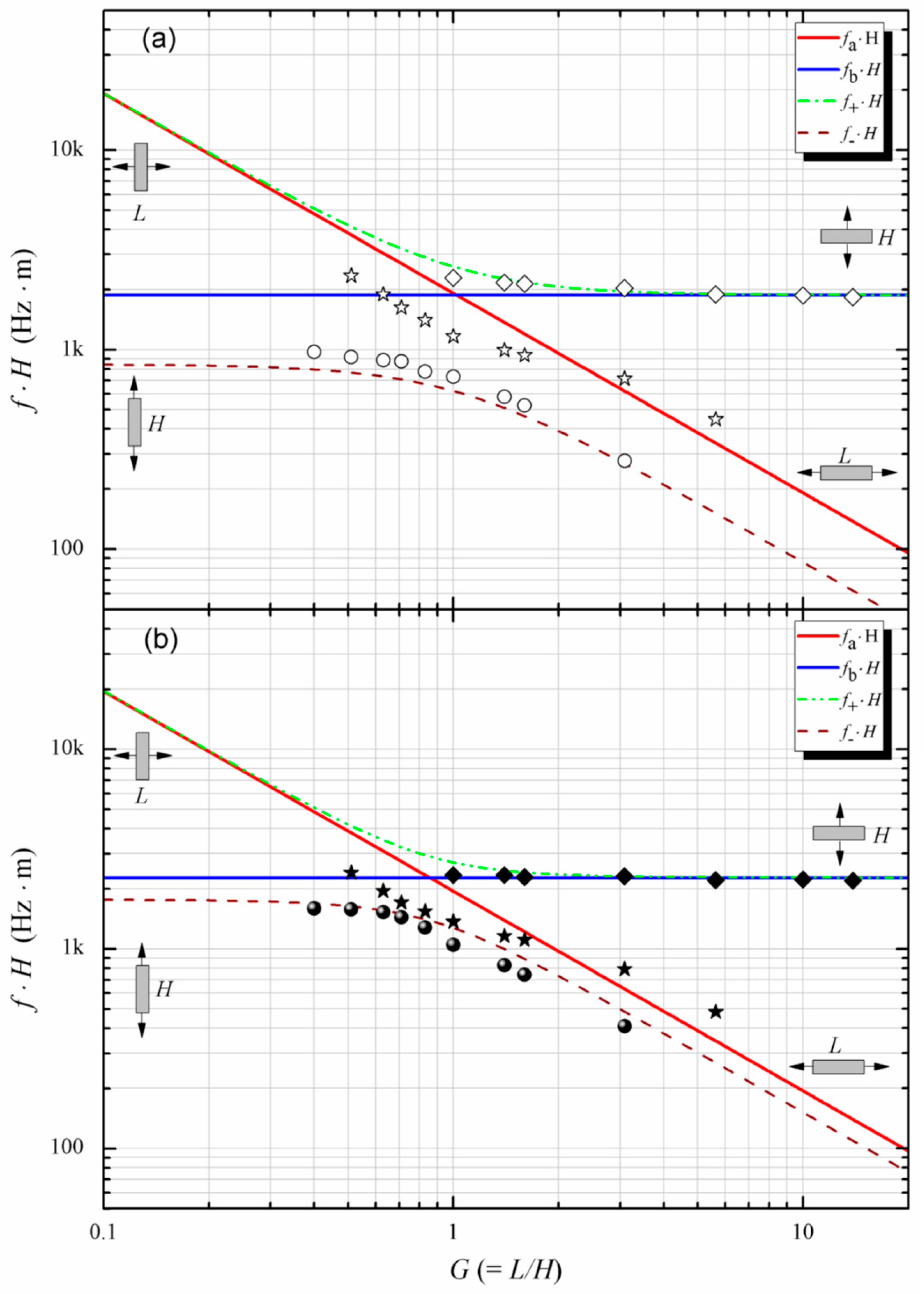
The width (lateral) mode. The lateral mode frequency fL is determined by the width L of the PIN–PMN–PT rectangular beams. When L is comparable with H, coupling of the modes fH1, fH2, and fL occurs. This mode-coupling effect can be predicted using the mode-coupling theory described in the following paragraph [14,15].
To obtain a physical insight into the effect of mode coupling in the PIN–PMN–PT rectangular beams illustrated in Figure 1, the resonance characteristics of the rectangular beams at megahertz frequencies is assumed to be controlled by L and H in the x- and z-directions, respectively. Therefore, a rectangular beam of such kind can be treated as an elastic object with two degrees of freedom which, in turn, are coupled through a single mechanism in accordance with the following biquadratic frequency equation [16,17]:
( f a 2 f 2 ) ( f b 2 f 2 ) = f a 2 f b 2 γ 2 ,
f a = 1 2 L c 11 ρ ,
f b = 1 2 H c 33 ρ ,
γ = c 13 c 11 c 33 ,
where fa is the uncoupled lateral mode frequency; fb is the uncoupled beam or plate mode frequency; γ is the coupling coefficient; c11, c12, c13, and c33 are the elastic stiffness coefficients of the rectangular beam, and ρ is the density of the rectangular beam. Equation (1) can be expressed in the following form:
f 2 = ( f a 2 + f b 2 ) ± ( f a 2 + f b 2 ) 2 4 f a 2 f b 2 ( 1 γ 2 ) 2 .
Substituting Equations (2) and (3) into Equation (5) and taking G = L/H, we have
f ± H = c 33 8 ρ ( 1 + 1 G 2 c 11 c 33 ± ( 1 + 1 G 2 c 11 c 33 ) 2 4 G 2 c 11 c 33 ( 1 γ 2 ) ) .
Equation (6) has two different solutions f+ and f, thus giving two different frequency branches: upper f+ branch and lower f branch. The coupled plate mode and the coupled beam mode are governed by these two frequency branches in terms of G.
In practice, the theoretical curves of the uncoupled (i.e., fa and fb) and coupled (i.e., f+ and f) mode frequencies at different G can be derived for both short-circuit and open-circuit conditions by substituting the piezoelectric material parameters with superscripts E and D into Equations (2), (3), and (6), respectively. Table 1 shows the piezoelectric material parameters of the PIN–PMN–PT single crystal for the present study [18]. It is noted that the measured series resonance frequency fs and parallel resonance frequency fp were compared with the mode-coupling predictions deduced using the short-circuit (E) parameters and open-circuit (D) parameters, respectively.
Figure 2 shows the measured electrical impedance and phase angle spectra of the PIN–PMN–PT rectangular beams with different L of 0.14–4.90 mm and different G of 0.4–14.0. When G is small (e.g., G = 0.4–0.7 in Figure 2a–d) such that the rectangular beams behave tall-narrow beams, the strongest resonance that appears quite steadily at the low frequency of ~2.5 MHz is the beam mode fH1, while the much weaker resonance that occurs initially at ~8 MHz (Figure 2a) shifts to the low-frequency side, and then couples with fH1 as a result of an increase in L (Figure 2b–d) is the lateral mode fL. This G range of <0.7 (Figure 2a–d) is preferable to develop single-frequency ultrasonic array transducers operating in uncoupled beam mode. When G is >0.7 (e.g., G = 0.8 in Figure 2e), fL starts to couple with fH1. By elevating G to 1.0–5.6 (Figure 2f–j), fL further decreases and couples with fH1, while the plate mode fH2 emerges and becomes the dominant mode at ~6.0 MHz. This highly coupled G range of 0.7–6.0 is unsuitable for single-frequency ultrasonic array transducer applications, but is capable of realizing multifrequency ultrasonic array transducers. It is interesting to note that the third harmonic of fH1 is detected and labeled as 3fH1. The even harmonics are not expected to be observed because the applied electric field has opposite polarities on the two electrode faces of the rectangular beams. By increasing G to >6.0 (e.g., G = 10.0 in Figure 2k and G = 14.0 in Figure 2l), fH1 becomes weakened and eventually negligible, while fL down-shifts to a frequency far below fH2. This G range of >6.0 (Figure 2k,l) gives a strong and clear fH2 at ~5.3 MHz and is desirable for fabricating single-frequency ultrasonic array transducers working in uncoupled plate mode.
The observed fH1, fL, and fH2 in Figure 2 for all rectangular beams with different G are summarized and plotted in Figure 3, together with the mode-coupling predictions (i.e., fa, fb, f+, and f) deduced using Equations (2), (3), and (6). Figure 3a,b plot the short-circuit (E) condition and the open-circuit (D) condition for each mode based on the series resonance frequency fs and the parallel resonance frequency fp, respectively. It is seen that the measured results agree with the mode-coupling predications, especially when G is <0.7 and >5.0. The dispersion between the measured results and the mode-coupling predications may be due to inaccurate material parameters and measurement errors. Nonetheless, the mode-coupling predictions are useful and can form an application guide for the design and control of preferred operational modes and frequencies in ultrasonic array transducers. Importantly, when G is small (i.e., G < 0.7), fL locates at the high-frequency side and is far away from fH1. This uncoupled fH1 with a high electromechanical coupling coefficient k’33 of ~0.75 can lead to beam-mode single-frequency ultrasonic array transducers at relatively low frequencies. When G is large (i.e., G > 6.0), fL occurs at the low-frequency side and again is far away from fH2. This uncoupled fH2 with a high electromechanical coupling coefficient kt of ~0.50 can result in plate-mode single-frequency ultrasonic array transducers with increased operational frequencies. When G is in the range of 1.6–3.1, fH1 not only couples with fL, but also coexists with fH2. These coupled/coexistent beam mode, lateral mode, and plate mode can be utilized to develop multifrequency ultrasonic array transducers.
Figure 4a shows the G dependence of the measured series resonance frequency fs and parallel resonance frequency fp for the beam mode (i.e., fH1) and the plate mode (i.e., fH2) in Figure 2. It is obvious that fs and fp of the beam mode drop slightly from 2.75 to 2.54 MHz and from 4.64 to 4.08 MHz, respectively, when G is increased from 0.4 to 0.7. After that, they drop rapidly and tend to merge with each other at ~1 MHz. For the plate mode, fs and fp separate gradually with increasing G from 1.0 to 5.6. They then remain relatively stable. Figure 4b gives the G dependence of the measured electromechanical coupling coefficient for the beam mode (k’33) and the plate mode (kt). For G ≤ 0.8, k’33 is as high as ~0.84, while kt is neglectable. At an elevated G of 0.8–5.6, there is an obvious drop in k’33 to ~0.75 and an emergence and increase in kt to ~0.50. When G is further elevated to 5.6, k’33 drops to ~0.35, while k t rises to ~0.56. Besides, a strong mode-coupling region is found in the G range of 1.6 to 3.1, in which both beam mode and plate mode coexist strongly and the corresponding electromechanical coefficients are ~0.75 and ~0.50, respectively.

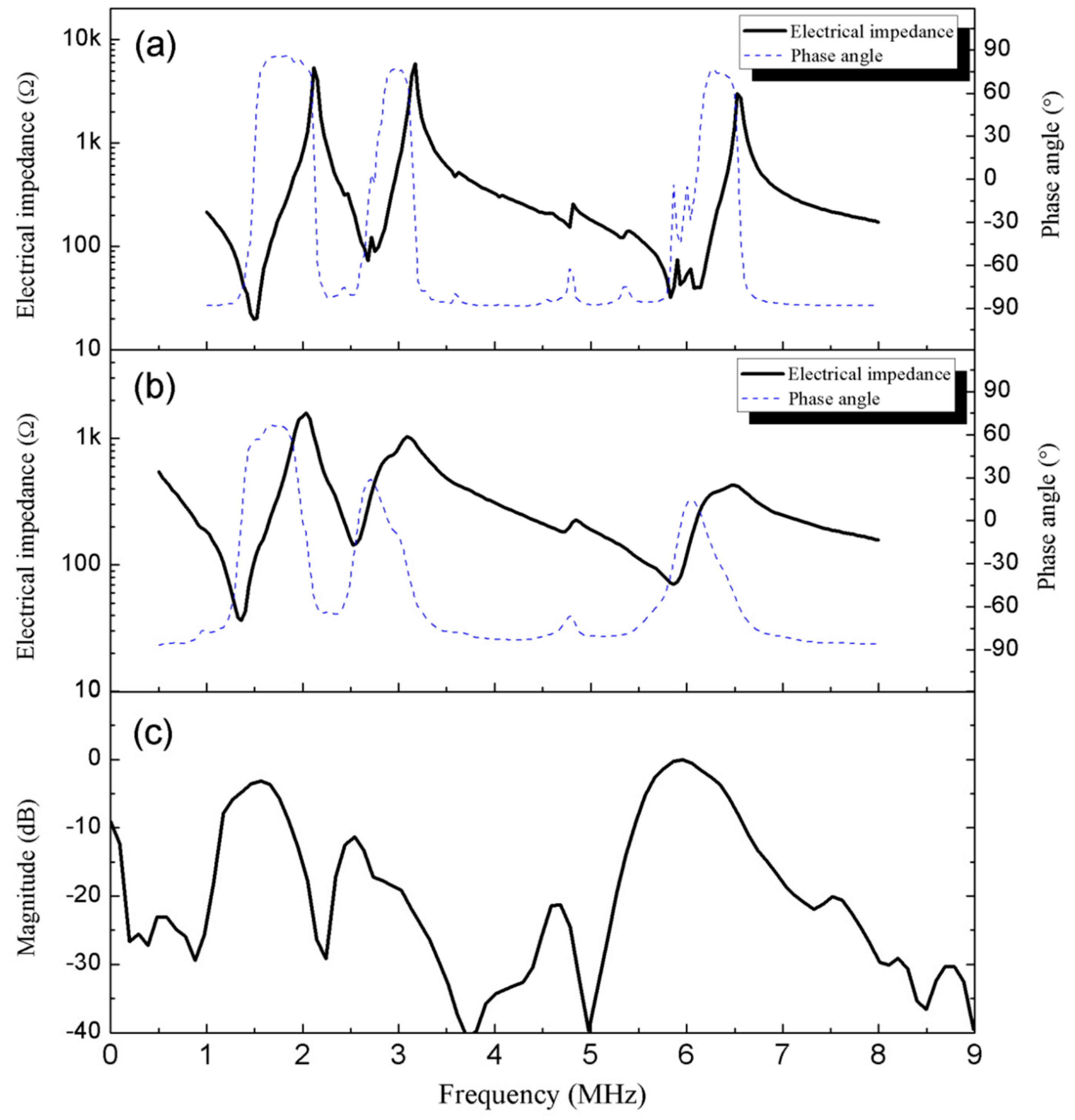
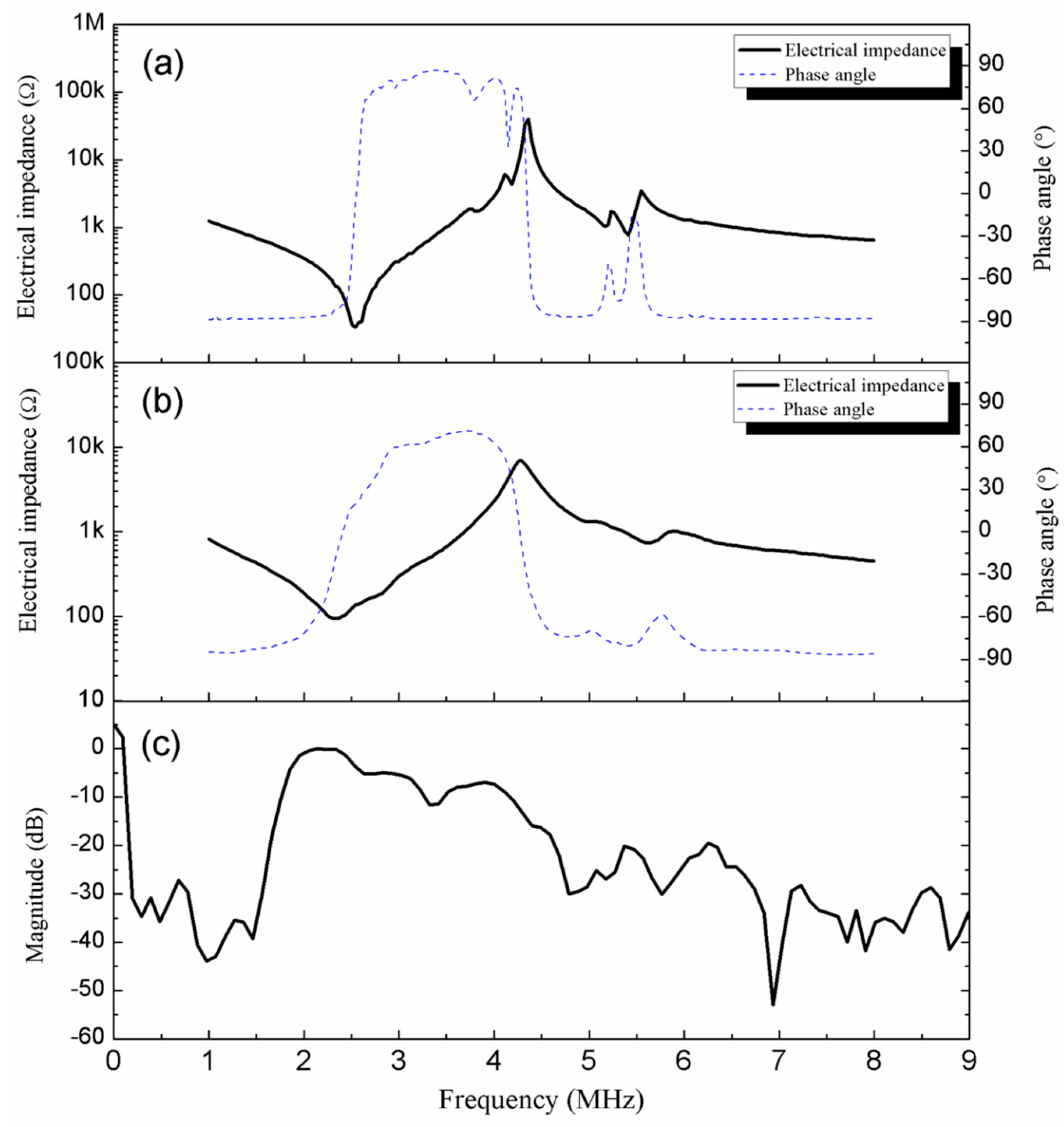
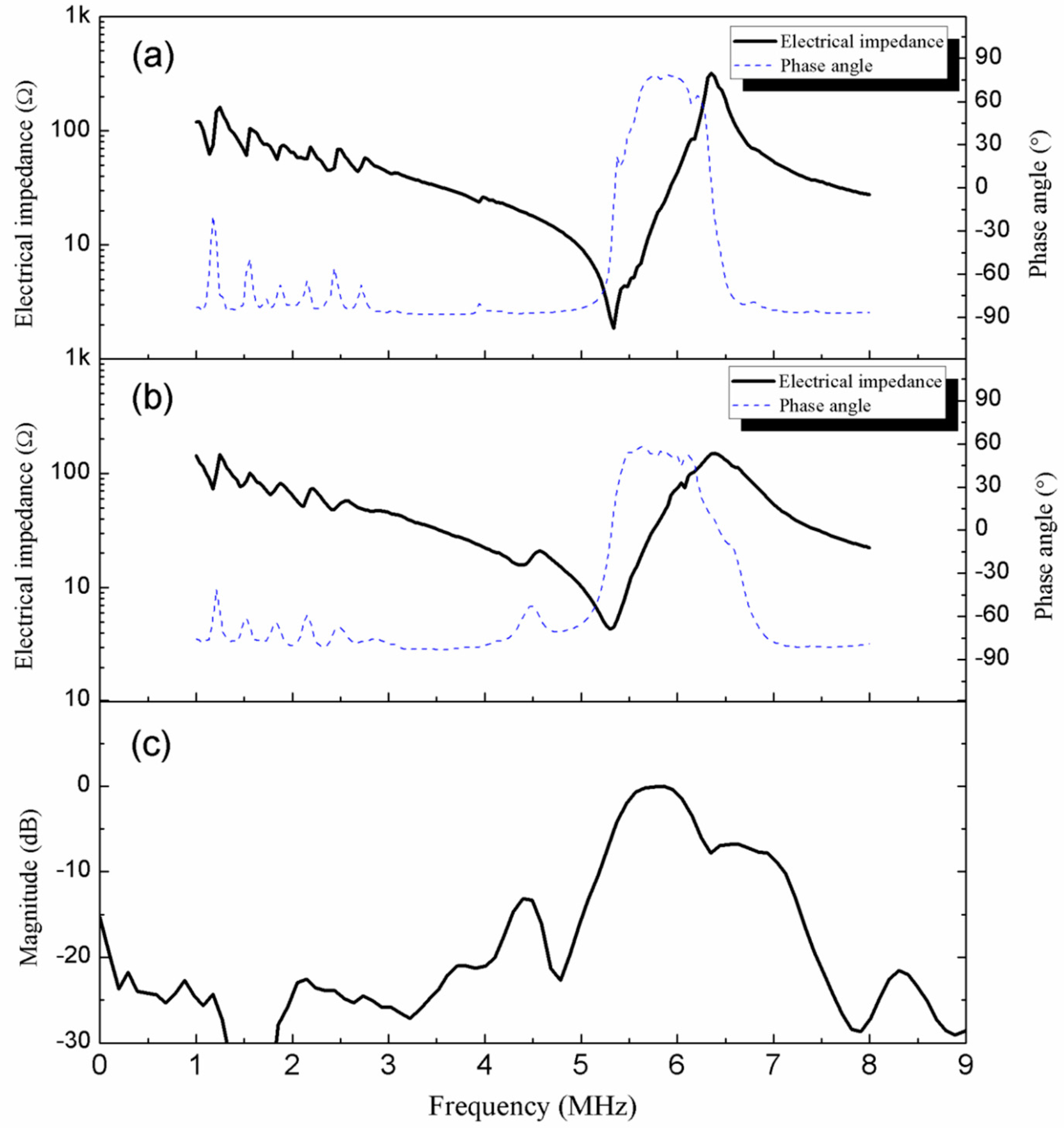
2.2. Performance of PIN–PMN–PT Multifrequency and Single-Frequency Ultrasonic Array Transducers

Figure 5a,b show the electrical impedance and phase angle spectra of a highly coupled PIN–PMN–PT rectangular beam with G = 1.6 and its resulting multifrequency ultrasonic array transducer, while Figure 5c illustrates the pulse-echo response spectrum of the multifrequency ultrasonic array transducer. From Figure 5a,b, there are three obvious electrical resonances at ~1.35, ~2.54, and ~5.87 MHz, corresponding to the coupled/coexistent beam mode, lateral mode, and plate mode of the mode-coupled rectangular beam (G = 1.6), respectively. The beam mode at ~1.35 MHz and the plate mode at ~5.87 MHz are both very strong. From Figure 5c, the three associated pulse-echo response peaks are found reasonably well at ~1.56, ~2.54, and ~5.97 MHz, respectively. According to Equations (9) and (10), the center frequency fC and −6 dB bandwidth BW−6dB of these three modes are determined to be 1.52 MHz and 46.5%, 2.60 MHz and 18.8% as well as 6.01 MHz and 15.2%, respectively.
Figure 6 and Figure 7 show the two single-frequency ultrasonic array transducers fabricated using two different uncoupled rectangular beams operating in uncoupled beam mode with G = 0.6 and uncoupled plate mode with G = 10.0, respectively. For the beam-mode ultrasonic array transducer in Figure 6, there is only one dominant pulse-echo response peak at ~2.3 MHz, with no strong peaks at high frequencies. For the plate-mode ultrasonic array transducer in Figure 7, similarly, there is only one dominant pulse-echo response peak at ~5.83 MHz, with no strong peaks at low frequencies. fC and BW−6dB of the beam-mode and plate-mode ultrasonic array transducers are found to be 2.24 MHz and 38.7% as well as 5.75 MHz and 15.8%, respectively.
Table 2 summarizes the design features and performance data of the multifrequency ultrasonic array transducer and the two single-frequency ultrasonic array transducers. Therefore, the mode-coupling effect in the PIN–PMN–PT rectangular beams play a crucial role in designing ultrasonic array transducers with controlled operational modes and frequencies.

3. Experiments for Materials and Transducers

3.1. Preparation of PIN–PMN–PT Rectangular Plates and Their Rectangular Beams

A high-quality relaxor-based ternary PIN–PMN–PT single crystal with the composition of 0.33PIN–0.35PMN–0.32PT was grown along the [111] crystallographic direction by a modified Bridgman technique [19,20]. High-purity oxide powders, including PbO, In2O3, MgO, Nb2O5, and TiO2, were used as the starting materials. After mixing the materials in accordance with the PIN:PMN:PT ratio of 0.33:0.35:0.32, the mixture was pre-synthesized with a two-step precursor route before being transferred into a sealed platinum crucible to prevent lead evaporation. An [111]-grown PIN–PMN–PT single crystal was employed as the seed crystal. The temperature profile used for the crystal preparation involved a rapid heating to 1400 °C and a soaking for 5 h. The seed crystal was dropped slowly at a rate of 0.1–0.8 mm/h through the heat zone into the platinum crucible. After the growth process, the furnace temperature was cooled at a rate of ~25 °C/h to room temperature.
The grown PIN–PMN–PT single crystal was oriented along the [001] direction using a X-ray diffractometer and then diced to (001) rectangular plates with dimensions of 30 mm (length) × 13 mm (width) × 0.35 mm (thickness) in the [010], [100] and [001] directions, respectively (Figure 1). After depositing with 500 nm-thick chromium/gold (Cr/Au) electrodes on the top and bottom surfaces normal to the thickness of the rectangular plates in the [001] direction by magnetron sputtering, the rectangular plates were poled along the [001] direction at room temperature under a dc electric field of 15 kV/cm for 15 min.
To prepare [001]-poled PIN–PMN–PT rectangular beams with a constant height H but with different widths L and hence different G (=L/H), the [001]-poled PIN–PMN–PT rectangular plates were diced along the width in the [100] direction using an 0.20 mm-thick nickel/diamond dicing blade mounted on a DAD 321 dicing saw (Disco Corp., Tokyo, Japan) (Figure 1). This gave various [001]-poled PIN–PMN–PT rectangular beams with the same length N of 13.0 mm along the y-axis and the same height H of 0.35 mm along the z-axis, but with different widths L of 0.14–4.90 mm along the x-axis and hence different width-to-height ratios G (=L/H) of 0.4–14.0.

3.2. Evaluation of PIN–PMN–PT Rectangular Beams

An impedance analyzer (Agilent 4294A) was used to measure the electrical impedance and phase angle spectra of the PIN–PMN–PT rectangular beams. According to the IEEE Standards on Piezoelectricity [21], the electromechanical coupling coefficients k 33 of the beam mode and k t of the plate mode, both in the PIN–PMN–PT rectangular beams, were determined, respectively, using the following relations:
k 33 = π 2 f s f p tan ( π 2 f p f s f p ) ,
k t = π 2 f s f p tan ( π 2 f p f s f p ) ,
where fs and fp are the series resonance frequency and parallel resonance frequency, respectively. In fact, the dimensions (i.e., L and H) of the rectangular cross-section and hence the value of G of the PIN–PMN–PT rectangular beams have the significant effects on their mode coupling and resonance characteristics, which have been discussed in Section 2.1. The electromechanical coupling coefficients of PZT piezoelectric resonators have been reported to depend heavily on the aspect ratio [22].

3.3. Fabrication of PIN–PMN–PT Multifrequency and Single-Frequency Ultrasonic Array Transducers

A multifrequency ultrasonic array transducer was fabricated based on the mode-coupling results obtained in Section 2.1. A PIN–PMN–PT rectangular plate with dimensions of 10 mm (length) × 13 mm (width) × 0.35 mm (thickness) was employed as the transduction element. An Araldite GY251/HY956 (100:18) epoxy layer cured on the bottom surface of the PIN–PMN–PT rectangular plate was used as the light backing layer without any front matching layer. The acoustic stack of the PIN–PMN–PT rectangular plate and the epoxy backing layer was diced along the width direction and into the backing layer at a depth of ~100 μm, thereby forming the PIN–PMN–PT rectangular beams. The diced width and center-to-center separation between two adjacent rectangular beams were measured to be 0.20 and 0.76 mm, respectively, so that the dimensions of the resulting PIN–PMN–PT rectangular beams were 13 mm (length N) × 0.56 mm (width L) × 0.35 mm (height H). This resulted in G = 1.6 in the strong mode-coupling region with a high k 33 of ~0.75 and a high kt of ~0.50. The core and ground wires of the coaxial cable were bonded on the top and bottom electrodes of the rectangular beams using an electrically conductive adhesive (E-solder 3022, Von Roll Isola USA Inc., Schenectady, NY, USA). Besides the multifrequency ultrasonic array transducer, two different single-frequency ultrasonic array transducers with their rectangular beams operating in uncoupled beam mode (G = 0.6) and uncoupled plate mode (G = 10.0) were fabricated using the same architecture and similar procedures for comparison.

3.4. Evaluation of PIN–PMN–PT Multifrequency and Single-Frequency Ultrasonic Array Transducers

The electrical impedance and phase angle spectra of the fabricated multifrequency and single-frequency ultrasonic array transducers were measured using a precision impedance analyzer (Agilent 4294A). Their transmission and reception performance was evaluated using a conventional pulse-echo response method [23]. The ultrasonic array transducer being evaluated was mounted on a holder and immersed in a water tank with a stainless steel target placed at its near field-far field transition, A / ( π λ ) , where A is the area of rectangular beams and λ is the acoustic wavelength in water at the center frequency of the ultrasonic array transducer. An ultrasonic pulser-receiver (Olympus Panametrics 5900PR) was employed to excite 1 μJ electrical impulses with 1 kHz repetition frequency to the ultrasonic array transducer. The time response of the echo was captured and displayed on a digitizing oscilloscope (Agilent Infinium 54810A). The frequency spectrum of the echo was obtained using the built-in FFT function of the digitizing oscilloscope. The center frequency fC and −6 dB bandwidth BW−6dB of the ultrasonic array transducer were determined from the measured pulse-echo response spectrum:
f C = 1 2 ( f 1 + f 2 ) ,
B W 6 dB = f 2 f 1 f C × 100 % ,
where f1 and f2 are the lower and upper −6 dB frequencies, respectively.

4. Conclusions

We have prepared PIN–PMN–PT single-crystal rectangular beams with 0.33:0.35:0.32 PIN:PMN:PT ratio and investigated both theoretically and experimentally their mode-coupling effect by changing their L and hence G value in order to extend the potential application of the PIN–PMN–PT single crystals to ultrasonic array transducers. We have found that the PIN–PMN–PT rectangular beams become tall-narrow beams and operate in uncoupled beam mode at G < 0.7; behave like short-wide plates and work in uncoupled plate mode at G > 6.0; and take an intermediate shape and function in strongly coupled/coexistent beam mode, lateral mode, and plate mode with high k’33 and k t of ~0.75 and ~0.50, respectively, in the G range of 1.6–3.1. With the guide of the mode-coupling results, we have developed a multifrequency ultrasonic array transducer based on a mode-coupled rectangular beam of G = 1.6 to impart three different operational modes of beam mode, lateral mode, and plate mode at three different operational frequencies of 1.52, 2.60, and 6.01 MHz, respectively. For comparison, we have also developed two different single-frequency ultrasonic array transducers using two different uncoupled rectangular beams of G = 0.6 and G = 10.0 to enable an uncoupled beam mode at 2.24 MHz and an uncoupled plate mode at 5.75 MHz, respectively. Our proposed multifrequency ultrasonic array transducer feature at least one low transmitting frequency (i.e., 1.52 or 2.60 MHz) and one high receiving frequency (i.e., 2.60 or 6.01 MHz) and may satisfy the requirements of deep penetration and high resolution in advanced medical ultrasonic imaging. Future work in this direction is in progress.

Acknowledgments

This work was supported by the Research Grants Council of the HKSAR Government (PolyU 5228/13E), The Hong Kong Polytechnic University (G-YK69), and the Natural Science Foundation of China (61405229).

Author Contributions

Wei Wang, as a PhD student of Siu Wing Or and Haosu Luo, performed both the theoretical and experimental work. Siu Wing Or conceived the project and guided Wei Wang in the study of the mode-coupling effect in the PIN–PMN–PT single-crystal rectangular beams, in the fabrication and evaluation of the ultrasonic array transducers, and in the writing of the current paper. Haosu Luo supported Wei Wang in the preparation of the PIN–PMN–PT single crystals.

Conflicts of Interest

The authors declare no conflict of interest.

References

  1. Zhou, D.; Cheung, K.F.; Lam, K.H.; Chen, Y.; Chiu, Y.C.; Dai, J.Y.; Chan, H.L.W.; Luo, H.S. Broad-band and high-temperature ultrasonic transducer fabricated using a Pb(In1/2Nb1/2)O3–Pb(Mg1/3Nb2/3)O3–PbTiO3 single crystal∕epoxy 1–3 composite. Rev. Sci. Instrum. 2011, 82, 055110. [Google Scholar] [CrossRef] [PubMed]
  2. Zhang, Y.Y.; Zhao, X.Y.; Wang, W.; Ren, B.; Liu, D.A.; Luo, H.S. Fabrication of PIMNT/epoxy 1–3 composites and ultrasonic transducer for nondestructive evaluation. IEEE Trans. Ultrason. Ferroelectr. Freq. Control 2011, 58, 1774–1781. [Google Scholar] [CrossRef] [PubMed]
  3. Wang, W.; Wang, S.; Zhang, Y.Y.; Zhao, X.Y.; Luo, H.S. Beam-mode piezoelectric properties of ternary Pb(In1/2Nb1/2)O3–Pb(Mg1/3Nb2/3)O3–PbTiO3 single crystals for medical linear array applications. J. Electron. Mater. 2011, 40, 2228–2233. [Google Scholar] [CrossRef]
  4. Chen, J.; Panda, R.; Rafter, P.G.; Gururaja, T.R. Wideband Piezoelectric Transducer for Harmonic Imaging. U.S. Patent 6532819 B1, 18 March 2003. [Google Scholar]
  5. Chen, J.; Panda, R. Review: Commercialization of piezoelectric single crystals for medical imaging applications. IEEE Ultrason. Symp. Proc. 2005, 1, 235–240. [Google Scholar]
  6. Service, R.F. Shape-changing crystals get shiftier. Science 1997, 275, 1878. [Google Scholar] [CrossRef]
  7. Lee, H.J.; Zhang, S.J.; Luo, J.; Li, F.; Shrout, T.R. Thickness-dependent properties of relaxor-PbTiO3 ferroelectrics for ultrasonic transducers. Adv. Funct. Mater. 2010, 20, 3154–3162. [Google Scholar] [CrossRef] [PubMed]
  8. Zhou, Q.F.; Lam, K.H.; Zheng, H.R.; Qiu, W.B.; Shung, K.K. Piezoelectric single crystal ultrasonic transducers for biomedical applications. Prog. Mater. Sci. 2014, 66, 87–111. [Google Scholar] [CrossRef] [PubMed]
  9. Xu, G.S.; Chen, K.; Yang, D.F.; Li, J.B. Growth and electrical properties of large size Pb(In1/2Nb1/2)O3–Pb(Mg1/3Nb2/3)O3–PbTiO3 crystals prepared by the vertical Bridgeman technique. Appl. Phys. Lett. 2007, 90, 032901. [Google Scholar] [CrossRef]
  10. Zhang, S.J.; Luo, J.; Hackenberger, W.; Sherlock, N.P.; Meyer, R.J., Jr.; Shrout, T.R. Electromechanical characterization of Pb(In0.5Nb0.5)O3–Pb(Mg1/3Nb2/3)O3–PbTiO3 crystals as a function of crystallographic orientation and temperature. J. Appl. Phys. 2009, 105, 104506. [Google Scholar] [CrossRef] [PubMed]
  11. Wang, W.; Zhao, X.Y.; Or, S.W.; Leung, C.M.; Zhang, Y.Y.; Jiao, J.; Luo, H.S. Broadband ultrasonic linear array using ternary PIN–PMN–PT single crystal. Rev. Sci. Instrum. 2012, 83, 095001. [Google Scholar] [CrossRef] [PubMed]
  12. Wang, W.; Or, S.W.; Yue, Q.W.; Zhang, Y.Y.; Jiao, J.; Ren, B.; Lin, D.; Leung, C.M.; Zhao, X.Y.; Luo, H.S. Cylindrically shaped ultrasonic linear array fabricated using PIMNT/epoxy 1–3 piezoelectric composite. Sens. Actuators A Phys. 2013, 192, 69–75. [Google Scholar] [CrossRef]
  13. Wang, W.; Or, S.W.; Yue, Q.W.; Zhang, Y.Y.; Jiao, J.; Leung, C.M.; Zhao, X.Y.; Luo, H.S. Ternary piezoelectric single-crystal PIMNT based 2–2 composite for ultrasonic transducer applications. Sens. Actuators A Phys. 2013, 196, 70–77. [Google Scholar] [CrossRef]
  14. Bui, T.; Chan, H.L.W.; Unsworth, J. A multifrequency composite ultrasonic transducer system. IEEE Ultrason. Symp. 1988, 2, 627–630. [Google Scholar]
  15. Or, S.W.; Chan, H.L.W. Mode coupling in lead zirconate titanate/epoxy 1–3 piezocomposite rings. J. Appl. Phys. 2001, 90, 4122–4129. [Google Scholar] [CrossRef]
  16. Selfridge, A.R. Design and Fabrication of Ultrasonic Transducer Arrays. Ph.D. Thesis, Stanford University, Stanford, CA, USA, 1982. [Google Scholar]
  17. Onoe, M.; Tiersten, H.F. Resonant frequencies of finite piezoelectric ceramic vibrators with high electromechanical coupling. IEEE Trans. Ultrason. Eng. 1963, 10, 32–38. [Google Scholar] [CrossRef]
  18. Luo, J.; Hackenberger, W.; Zhang, S.J.; Shrout, T.R. Elastic, piezoelectric and dielectric properties of PIN–PMN–PT crystals grown by Bridgman method. IEEE Ultrason. Symp. Proc. 2008, 1–4, 261–264. [Google Scholar]
  19. Zhang, Y.Y.; Li, X.B.; Liu, D.A.; Zhang, Q.H.; Wang, W.; Ren, B.; Lin, D.; Zhao, X.Y.; Luo, H.S. The compositional segregation, phase structure and properties of Pb(In1/2Nb1/2)O3–Pb(Mg1/3Nb2/3)O3–PbTiO3 single crystal. J. Cryst. Growth 2011, 318, 890–894. [Google Scholar] [CrossRef]
  20. Wang, W.; Li, X.B.; Or, S.W.; Leung, C.M.; Jiao, J.; Zhang, Y.Y.; Zhao, X.Y.; Luo, H.S. Temperature dependence of dielectric polarization and strain behaviors for rhombohedral PIMNT single crystal with different crystallographic orientations. J. Alloys Compd. 2012, 545, 57–62. [Google Scholar] [CrossRef]
  21. ANSI/IEEE Std. 176-1987, IEEE Standard on Piezoelectricity; The Institute of Electrical and Electronics Engineers: New York, NY, USA, 1987.
  22. Kim, M.; Kim, J.S.; Cao, W.W. Aspect ratio dependence of electromechanical coupling coefficient of piezoelectric resonators. Appl. Phys. Lett. 2005, 87, 132901. [Google Scholar] [CrossRef]
  23. Desilets, C.S.; Fraser, J.D.; Kino, G.S. The design of efficient broad-band piezoelectric transducers. IEEE Trans. Sonics Ultrason. 1978, 25, 115–125. [Google Scholar] [CrossRef]
Figure 1. Schematic diagram of the crystallographic orientation and poling direction of an as-prepared PIN–PMN–PT rectangular plate of 0.33:0.35:0.32 PIN:PMN:PT ratio, together with its rectangular beams having the same length N and height H but with different widths L and hence different width-to-height ratios G (=L/H).
Crystals 07 00101 g001
Figure 2. Measured electrical impedance and phase angle spectra of PIN–PMN–PT rectangular beams with different G (=L/H) of (a) 0.4; (b) 0.5; (c) 0.6; (d) 0.7; (e) 0.8; (f) 1.0; (g) 1.4; (h) 1.6; (i) 3.1; (j) 5.6; (k) 10.0; and (l) 14.0.
Crystals 07 00101 g002
Figure 3. Frequency constants (f·H) of PIN–PMN–PT rectangular beams as a function of G for (a) short-circuit (E) condition based on series resonance frequency fs and (b) open-circuit (D) condition based on parallel resonance frequency fp. The lines represent the mode-coupling predictions, while the symbols indicate the observed fH1, fL, and fH2 in Figure 2.
Crystals 07 00101 g003
Figure 4. Distributions of (a) series and parallel resonance frequencies fs and fp and (b) electromechanical coupling coefficients k 33 and k t with different G.
Crystals 07 00101 g004
Figure 5. (a) Electrical impedance and phase angle spectra of a PIN–PMN–PT rectangular beam with G = 1.6 and operating in coupled/coexistent beam mode, lateral mode, and plate mode; (b) electrical impedance and phase angle spectra of the resulting multifrequency ultrasonic array transducer; (c) pulse-echo response spectrum of the multifrequency ultrasonic array transducer in (b).
Crystals 07 00101 g005
Figure 6. (a) Electrical impedance and phase angle spectra of a PIN–PMN–PT rectangular beam with G = 0.6 and operating in uncoupled beam mode; (b) electrical impedance and phase angle spectra of the resulting beam-mode single-frequency ultrasonic array transducer; (c) pulse-echo response spectrum of the beam-mode single-frequency ultrasonic array transducer in (b).
Crystals 07 00101 g006
Figure 7. (a) Electrical impedance and phase angle spectra of a PIN–PMN–PT rectangular beam with G = 10.0 and operating in uncoupled plate mode; (b) electrical impedance and phase angle spectra of the resulting plate-mode single-frequency ultrasonic array transducer; (c) pulse-echo response spectrum of the plate-mode single-frequency ultrasonic array transducer in (b).
Crystals 07 00101 g007
Table 1. Piezoelectric material parameters of as-prepared Pb(In1/2Nb1/2)O3–Pb(Mg1/3Nb2/3)O3–PbTiO3 (PIN–PMN–PT) single crystal with 0.33:0.35:0.32 PIN:PMN:PT ratio.
ρ = 8100 kg/m3
c 11 E = 119 GN/m2 c 11 D = 123 GN/m2
c 12 E = 105 GN/m2 c 12 D = 109 GN/m2
c 13 E = 104 GN/m2 c 13 D = 90 GN/m2
c 33 E = 114 GN/m2 c 33 D = 167 GN/m2
Table 2. Summary of design features and performance data of multifrequency ultrasonic array transducer and two single-frequency ultrasonic array transducers.
Design Features and Performance DataMultifrequency Ultrasonic Array TransducerBeam-Mode Single-Frequency Ultrasonic Array TransducerPlate-Mode Single-Frequency Ultrasonic Array Transducer
Width-to-height ratio G1.60.610.0
Operational mode(s)Coupled/coexistent beam mode fH1, lateral mode fL, plate mode fH2Uncoupled beam mode fH1Uncoupled plate mode fH2
Center frequency fC (MHz)1.52, 2.60, 6.012.245.75
−6 dB bandwidth BW−6dB (%)46.5, 18.8, 15.238.715.8
Backing layerAraldite GY251/HY956 (100:18) epoxy layer
Front matching layerNil

