
Validation of the Concurrent Atomistic-Continuum Method on Screw Dislocation/Stacking Fault Interactions


1
The George W. Woodruff School of Mechanical Engineering, Georgia Institute of Technology, Atlanta, GA 30332-0405, USA
2
Department of Aerospace Engineering, Iowa State University, Ames, IA 50011, USA
3
Department of Mechanical and Aerospace Engineering, University of Florida, Gainesville, FL 32611-6250, USA
4
School of Materials Science and Engineering, Georgia Institute of Technology, Atlanta, GA 30332-0245, USA
*
Author to whom correspondence should be addressed.
Crystals 2017, 7(5), 120; https://doi.org/10.3390/cryst7050120
Submission received: 7 March 2017
/
Revised: 10 April 2017
/
Accepted: 19 April 2017
/
Published: 26 April 2017
(This article belongs to the Special Issue Plasticity of Crystals and Interfaces)
Abstract
:Dislocation/stacking fault interactions play an important role in the plastic deformation of metallic nanocrystals and polycrystals. These interactions have been explored in atomistic models, which are limited in scale length by high computational cost. In contrast, multiscale material modeling approaches have the potential to simulate the same systems at a fraction of the computational cost. In this paper, we validate the concurrent atomistic-continuum (CAC) method on the interactions between a lattice screw dislocation and a stacking fault (SF) in three face-centered cubic metallic materials—Ni, Al, and Ag. Two types of SFs are considered: intrinsic SF (ISF) and extrinsic SF (ESF). For the three materials at different strain levels, two screw dislocation/ISF interaction modes (annihilation of the ISF and transmission of the dislocation across the ISF) and three screw dislocation/ESF interaction modes (transformation of the ESF into a three-layer twin, transformation of the ESF into an ISF, and transmission of the dislocation across the ESF) are identified. Our results show that CAC is capable of accurately predicting the dislocation/SF interaction modes with greatly reduced DOFs compared to fully-resolved atomistic simulations.
1. Introduction
Stacking faults (SFs) are planar defects that are commonly observed in face-centered cubic (FCC) metals during plastic deformation [1]. Depending on how the stacking sequence is disturbed, two types of SFs are possible: intrinsic SF (ISF) and extrinsic SF (ESF) [1]. For example, in nanocrystalline Al with an average grain size smaller than 18 nm, an ISF transecting a grain can be formed when a leading partial dislocation nucleated from grain boundaries and triple junctions transits across the grain without the nucleation of a trailing partial dislocation [2]. Thereafter, another dislocation on an intersecting slip plane may interact with the ISF, altering its stacking sequence [3]. In other words, ISFs may serve as barriers to dislocation motion, resulting in a higher yield stress. Through a set of molecular dynamics (MD) simulations of screw dislocation/SF interactions in five FCC metals, Wei and Wei [4] identified three reaction modes for the ISF (i.e., transformation into an ESF, annihilation, and direct transmission of the dislocation) and the ESF (i.e., transformation into a three-layer twin, transformation into an ISF, and direct transmission of the dislocation), respectively. In the same material, the specific interaction mode depends on both applied shear strain and boundary condition [5]. Across materials, the SF energy (SFE) is usually considered one of the most important material parameters that influence these interactions [6]. The significance of the SFE has also been confirmed in previous MD simulations [7,8,9,10,11,12] of interactions between a screw dislocation and a coherent twin boundary, which shares structural similarity to SFs.
While MD has been widely employed to study problems involving dislocations and SFs, the size of its simulation cell is usually limited to less than 50 nm. On the other hand, dislocations interactions fields are long range. Therefore, multiscale modeling techniques such as the concurrent atomistic-continuum (CAC) method [13] are especially useful in describing dislocation behavior at length scales that are typically inaccessible to most classical atomistic methods such as MD. Unlike many other coarse-grained atomistic approaches, CAC admits propagation of displacement discontinuities (dislocations and associated ISFs) through a lattice in both atomistic and coarse-grained domains, by employing a unified atomistic-continuum integral formulation with elements that have discontinuities between them. In quasistatic CAC, the goal is to minimize the internal energy of the system, which has contributions from both atomistic and coarse-grained domains [13]. In the coarse-grained domain, the internal energy is a function of the nodal forces and the nodal displacements, which are solved through finite element equations using first order Gaussian quadrature; the nonlocal nonlinear force-displacement relationship within and between elements are obtained from the atomistic force field, i.e., from the interatomic potential, which is the only constitutive relation.
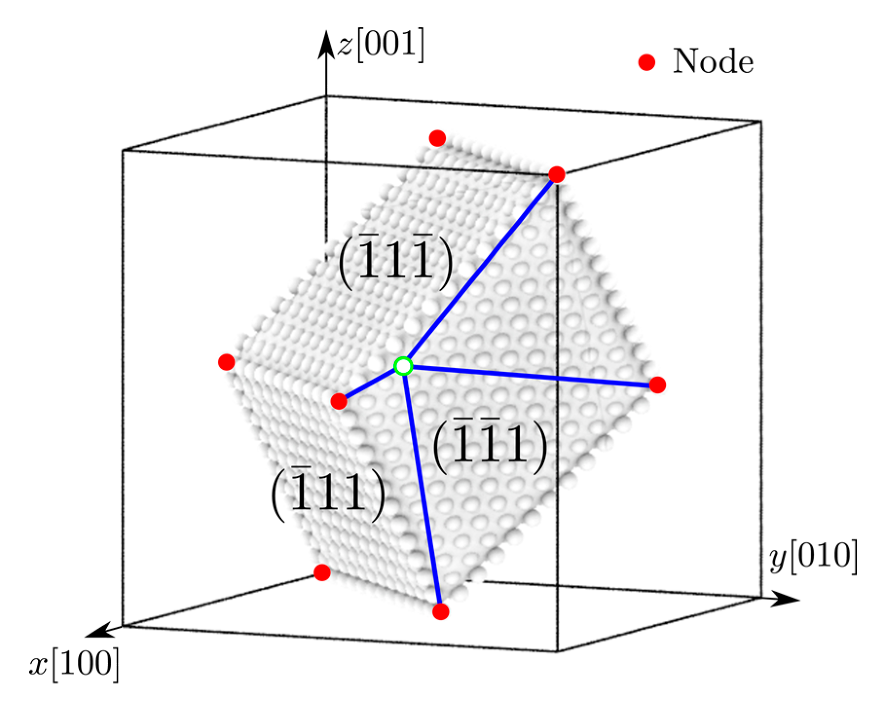
To accommodate dislocations in the coarse-grained domain in an FCC lattice, the rhombohedral isoparametric elements with all faces on {111} slip planes are employed, as shown in Figure 1. It follows that the atomic positions are linearly interpolated from the nodal positions. As such, each element is assumed as a hyperelastic body. According to linear elasticity theory, the stress field of one dislocation at a long distance is mainly determined by its Burgers vector and character angle, which are accurately tracked in the coarse-grained domain as described in our previous work [13]. As a result, the coarse-grained domain in CAC preserves both core effects and long range stress fields of dislocations.
However, because of the linear interpolation function used in the current CAC implementation, only line defects (e.g., dislocations) and planar defects with a thickness up to two atomic layers (e.g., ISFs) can be accommodated between elements, as shown in Figure 2a,b. Planar defects involving three or more adjacent atomic layers, e.g., ESFs and three-layer twins, cannot be readily described between rhombohedral elements [14]. So far, two approaches have been introduced into CAC for these multi-layer planar defects: (i) developing ribbon elements whose thickness is dictated by that of the planar defect [15]; and (ii) locally refining elements to atomic scale such that planar defects are rendered at full atomistic resolution [16].
For screw dislocation/ISF interactions, the ISF can be accommodated between rhombohedral elements, as shown in Figure 2b, yet the transformation of an ISF into an ESF, a possible outcome of interactions with dislocations [4], would not be permitted. However, the other two interaction modes, i.e., annihilation of the ISF and direct transmission of the screw dislocation across the ISF [4], can be accommodated between rhombohedral elements because these two modes do not increase the thickness of the SF. Similarly, for screw dislocation/ESF interactions, the transformation of an ESF into a three-layer twin would not be allowed by introducing only one layer of atoms between elements, as shown in Figure 2c. On the other hand, transformation of an ESF into an ISF and direct transmission of the screw dislocation across the ESF can in principle be modelled using rhombohedral elements with one layer of atoms in between. Therefore, it is interesting to validate these hypotheses and explore how each interaction mode operates in CAC simulations. From the methodological viewpoint, we will show that with a significant reduction in the degrees of freedom (DOFs), CAC is able to simulate dislocation/SF interactions, an important building block for coarse-grained modeling of more complicated dislocation/microstructure interactions in the bulk.
2. Materials and Methods
Figure 3a presents the computational cell used to study the interactions between a screw dislocation and an ISF or an ESF in a single crystal for three FCC metals: Ni, Al, and Ag. The lattice orientations are , , and . Periodic boundary conditions (PBCs) are applied along the x direction, while nodes/atoms within 2 nm from boundaries along the other two axes are fixed. Four models, Model-AT, Model-0, Model-1, and Model-2, are constructed and distinguished by the number of layers of atoms introduced between elements, as shown in Figure 3b–f. In all models, atoms are used to fill in along the jagged surfaces provided by elements of exterior boundaries to create smooth surfaces [13,18,19]. Around the SF, Model-AT introduces an atomistic domain with a thickness of 3 nm, and Model-0 contains only rhombohedral elements with surfaces corresponding to {111} slip planes, while Model-1 and Model-2 introduce one and two layers of atoms between rhombohedral elements, respectively. In the coarse-grained domain, second nearest neighbor elements [13] with a uniform size corresponding to 2197 atoms per element are adopted. Within each element, piecewise continuous first order shape and interpolation functions are employed; between elements, neither displacement continuity nor interelement compatibility is required. Each simulation cell contains 1510 elements and about 1 million atoms; as a result, the largest model, Model-AT, has 1,194,066 DOFs in total compared with 4,499,456 DOFs in an equivalent full atomistic model. The simulation cell size, which in the three materials differs only by their lattice parameter (3.52 Å for Ni, 4.05 Å for Al, and 4.09 Å for Ag), is 30.08 nm by 69.39 nm by 36.76 nm for Ag. The embedded-atom method (EAM) potentials of Mishin et al. [20] (for Ni and Al) and Williams et al. [21] (for Ag) are employed for interatomic interactions.
By shifting two adjacent atomic planes against each other by , an ISF is constructed, as shown in Figure 3b,c. Repeating the shift between an adjacent set of two planes results in an ESF, as shown in Figure 3d–f. At about 23 nm left of the SF, a straight screw dislocation with Burgers vector is introduced using a Volterra knife in the coarse-grained domain, following our earlier work [18,19]. The screw dislocation is considered infinitely long because of the PBCs imposed along its length direction (x axis). First, both the dislocation and SF are energy minimized using a conjugate gradient method [13]. Then, a simple shear strain γzx is applied by fixing the lower boundary while displacing the upper boundary along the positive x direction (boundaries are normal to the z axis); all nodes and atoms in the left and right boundaries (normal to the y axis) are displaced linearly in the x direction, as shown in Figure 3a. Subsequently, the quasistatic CAC is performed to minimize the total internal energy of the system. The energy minimization is considered to converge when the absolute energy variation between successive iterations divided by the energy magnitude of the latest iteration is smaller than 10−5. The temperature of the 3D system is effectively 0 K, making our results comparable to previous fully 3D MD simulations at 0.1 K [4] or 2 K [5]. Different shear strain levels with an increment of 1% are employed to assess the strain-dependent interaction mode. In the coarse-grained domain, post-processing is performed after the atomic positions are interpolated from the nodal positions. Simulation results are visualized using ParaView [22] and OVITO [23]. Simulations in this paper are performed using clusters Comet and Bridges on Extreme Science and Engineering Discovery Environment (XSEDE) [24].
3. Results and Discussion
For all three materials, the [110] full screw dislocation dissociates into two [112]
Shockley partial dislocations upon energy minimization [13,18,19], i.e.,:
First, the applied shear strain γzx and the corresponding resolved shear stress need to be sufficiently high to overcome the Peierls stress in the coarse-grained domain [25] to set the screw dislocation in motion. Once reaching the SF, the two partial dislocations begin to come together. The recombination reaction of the two partial dislocations into a perfect screw dislocation at the SF occurs at a critical γzx of 1.1%, 0.6%, and 1.5% for Ni, Al, and Ag, respectively, and is given by:
Note that reaction (2) is always followed at the SF before any further motion can proceed. In other words, the leading dislocation is not absorbed by or transmitted across the SF when the trailing partial is still to the left of the SF. The full dislocation will then react with the ISF/ESF following different interaction modes. Therefore, only the simulation results with γzx ≥ 2% are discussed in the remainder of this paper.
3.1. Intrinsic Stacking Fault
Two screw dislocation/ISF interaction modes are observed:
(i) the full dislocation dissociates into two Shockley partials on the ISF plane, i.e.,:
which then propagate oppositely and annihilate the ISF, as shown in Figure 4b;
(ii) the full dislocation is transmitted across the ISF and glides on a plane that is lower than the incoming slip plane along the z direction. Then the leading partial dislocation is nucleated from the ISF, followed by the nucleation of the trailing partial dislocation, as shown in Figure 4c. The re-dissociation of the full dislocation to the right side of the ISF follows reaction (1).
Table 1 presents dislocation/ISF interaction modes for a variety of materials, models, and applied shear strains. For these two interaction modes in which the ISF is either annihilated or penetrated, Model-0 predicts the same interaction mode as Model-AT for all materials and shear strains. This validates our earlier hypothesis that rhombohedral elements alone can describe certain dislocation/ISF interactions in which the thickness of the SF does not increase.
All materials exhibit annihilation of the ISF, while Ni and Ag also experience dislocation transmission across the ISF with an increasing applied shear strain, a common sequence for screw dislocation/ISF interactions [4,5]. Previous MD simulations [4] found that whether the ISF is annihilated or penetrated depends on a competition between the nucleation of the trailing partial dislocation along the ISF and the nucleation of the leading partial dislocation on the other side of the ISF. More specifically, the smaller the ratio of the stable SFE to the unstable SFE, the more likely the screw dislocation is transmitted across the ISF subject to the same applied shear strain. Among the three materials in the present work, this ratio is 0.34 for Ni, 0.87 for Al, and 0.16 for Ag [4,20,21]. As such, Ag requires the lowest minimum strain (3%) for dislocation transmission, and only the ISF annihilation is observed in Al with γzx up to 6%. Note that in Al, the ISF is annihilated even in the absence of an incoming lattice dislocation when γzx ≥ 7%; specifically, the restoration of the perfect lattice arrangement is initiated at a random location in the ISF and spreads out across the ISF, as marked by the open circle and arrows in Figure 4. This shear-induced ISF annihilation is not observed in Ni and Ag for γzx up to 10%.
3.2. Extrinsic Stacking Fault
Three screw dislocation/ESF interaction modes are observed:
(i) the full dislocation dissociates into two Shockley partials adjacent to the first HCP plane, i.e.,:
which then transform the ESF into a three-layer twin, as shown in Figure 5b;
(ii) the full dislocation dissociates into two Shockley partials adjacent to the second HCP plane following reaction (3), transforming the ESF to an ISF, as shown in Figure 5c;
(iii) the full dislocation is transmitted across the ESF and glides on a plane that is lower than the incoming slip plane along the z direction. Then, the leading partial dislocation is nucleated from the ESF, followed by the nucleation of the trailing partial dislocation, as shown in Figure 5d. The re-dissociation of the full dislocation to the right side of the ESF follows reaction (1).
Table 2 presents dislocation/ESF interaction modes for a variety of materials, models, and applied shear strains. It is found for all materials and shear strains that Model-2 always predicts the same interaction mode as Model-AT. Model-1, however, only correctly captures dislocation transmission and transformation of the ESF into an ISF. While Model-AT predicts that the ESF is transformed into a three-layer twin, e.g., when γzx = 2% in all three materials, Model-1 predicts the transformation of the ESF into an ISF, which is clearly aphysical. This suggests that (i) Model-1 is applicable only when the ESF does not increase its thickness (e.g., transformed into a three-layer twin) and (ii) Model-2 is viable to replace Model-AT to reduce the DOFs while accurately replicating all possible single dislocation/ESF interaction modes. Note that the three-layer twin may be transformed into a four-layer twin upon impingement of an additional incoming screw dislocation; for this reaction, Model-2 is no longer applicable, giving rise to the need for a new model with three layers of atoms between rhombohedral elements.
With an increasing applied shear strain, Ni and Ag exhibit transformation of the ESF into a three-layer twin, transformation of the ESF into an ISF, and dislocation transmission across the ESF, while Al exhibits only the first and the last interaction modes. Previous MD simulations [4] found that the transmission of a screw dislocation across an ESF is favored in materials with a large ratio of the twin boundary migration energy to the unstable SFE. Among the three materials in this paper, this ratio is 0.82 for Ni, 0.42 for Al, and 0.92 for Ag [4,20,21]. Hence, Al and Ag have the highest (6%) and the lowest (4%) minimum strain for dislocation transmission, respectively. In contrast to the case of an ISF, no shear-induced annihilation of the ESF is observed for all three materials for γzx up to 10%.
3.3. Coarse-Graining Efficiency
The coarse-graining efficiency of the quasistatic CAC was discussed in detail in Reference [13]. In this paper, the energy minimization is considered to converge when the absolute energy variation between successive iterations divided by the current energy magnitude is smaller than 10−5. The runtime t for the models in Figure 3b–f, as well as a fully-resolved atomistic model of the same size (i.e., all atoms without any coarse-graining), is presented in Table 3 for the case of dislocation/ISF interactions in Ni subject to an applied shear strain of 3%. The coarse-graining efficiency ψ is calculated with respect to the runtime of the fully-resolved atomistic model. It is found that Model-0 has the highest ψ of 8.47. In other words, within the runtime of a fully-resolved atomistic simulation, more than eight CAC simulations with the Model-0 can be conducted. This highlights the advantage of CAC in facilitating parametric studies, which are useful in many common metal plasticity problems involving different materials, applied stresses/strains, dislocation types, boundary conditions, etc. We remark that while Model-AT results in nearly the same speedup as Model-0, introducing atoms between any two elements (as in Model-AT) would be cumbersome for 3D bulk lattice interactions, for which the fully coarse-grained model, i.e., Model-0, will be more useful and efficient.
4. Conclusions
In this paper, we performed CAC simulations to study the screw dislocation/SF interactions in three FCC metals. Results are summarized as follows:
1. Two dislocation/ISF interaction modes are observed in Ni and Ag: annihilation of the ISF and the transmission of the screw dislocation across the ISF. In Al, the ISF is always annihilated by the dislocation when the applied shear strain γzx ≤ 6%; with a higher γzx, the ISF is annihilated even in the absence of the lattice dislocation. CAC simulations with only rhombohedral elements around the ISF predict accurate dislocation/ISF interaction modes for the three materials within the range of strains applied in this paper;
2. Three dislocation/ESF interaction modes are observed in Ni and Ag: transformation of the ESF into a three-layer twin, transformation of the ESF into an ISF, and transmission of the dislocation across the ESF. In Al, only the first and the last modes are observed. CAC simulations with two layers of atoms between rhombohedral elements predict all three dislocation/ESF interaction modes correctly, while those with only one layer of atoms between elements fail to predict the transformation of the ESF into a three-layer twin.
We emphasize that it is not our intent here to improve understanding of screw dislocation/SF interactions, which have been explored in References [4,5]. Rather, this paper establishes the applicability of the CAC approach to predict dislocation/SF interaction modes with greatly reduced DOFs compared with fully-resolved atomistic simulations. Future work includes developing adaptive mesh refinement schemes in CAC [16] which can automatically adjust the number of layers of atoms between rhombohedral elements, exploring the dislocation/SF interactions at finite temperature using dynamic CAC, and investigating more complicated dislocation/microstructure interactions in materials from nano- to micro-scales.
Acknowledgments
Liming Xiong acknowledges the support from the Department of Energy, Office of Basic Energy Sciences under Award Number DE-SC0006539. The work of Liming Xiong was also supported in part by the National Science Foundation under Award Number CMMI-1536925. Any opinions, findings, and conclusions or recommendations expressed in this material are those of the authors and do not necessarily reflect the views of the National Science Foundation. The authors thank Thomas G. Payne for helpful discussions. This work used the Extreme Science and Engineering Discovery Environment (XSEDE), which is supported by National Science Foundation grant number ACI-1053575.
Author Contributions
Under the direction of David L. McDowell and Youping Chen, Shuozhi Xu conceived the research, performed computer simulations, and wrote the paper. Shuozhi Xu and Liming Xiong developed the model and analyzed the data. All authors discussed the results and revised the paper.
Conflicts of Interest
The authors declare no conflict of interest.
References
- Hull, D.; Bacon, D.J. Introduction to Dislocations, 5th ed.; Butterworth-Heinemann: Oxford, UK, 2011. [Google Scholar]
- Yamakov, V.; Wolf, D.; Phillpot, S.R.; Mukherjee, A.K.; Gleiter, H. Deformation-mechanism map for nanocrystalline metals by molecular-dynamics simulation. Nat. Mater. 2004, 3, 43–47. [Google Scholar] [CrossRef] [PubMed]
- Yamakov, V.; Wolf, D.; Phillpot, S.R.; Gleiter, H. Dislocation-dislocation and dislocation-twin reactions in nanocrystalline Al by molecular dynamics simulation. Acta Mater. 2003, 51, 4135–4147. [Google Scholar] [CrossRef]
- Wei, H.; Wei, Y. Interaction between a screw dislocation and stacking faults in FCC metals. Mater. Sci. Eng. A 2012, 541, 38–44. [Google Scholar] [CrossRef]
- Mianroodi, J.R.; Svendsen, B. Modeling dislocation-stacking fault interaction using molecular dynamics. Proc. Appl. Math. Mech. 2013, 13, 11–14. [Google Scholar] [CrossRef]
- Zhu, Y.T.; Wu, X.L.; Liao, X.Z.; Narayan, J.; Kecskés, L.J.; Mathaudhu, S.N. Dislocation-twin interactions in nanocrytalline fcc metals. Acta Mater. 2011, 59, 812–821. [Google Scholar] [CrossRef]
- Fang, Q.; Sansoz, F. Influence of intrinsic kink-like defects on screw dislocation—Coherent twin boundary interactions in copper. Acta Mater. 2017, 123, 383–393. [Google Scholar] [CrossRef]
- Jin, Z.-H.; Gumbsch, P.; Ma, E.; Albe, K.; Lu, K.; Hahn, H.; Gleiter, H. The interaction mechanism of screw dislocations with coherent twin boundaries in different face-centered cubic metals. Scr. Mater. 2006, 54, 1163–1168. [Google Scholar] [CrossRef]
- Zhu, T.; Li, J.; Samanta, A.; Kim, H.G.; Suresh, S. Interfacial plasticity governs strain rate sensitivity and ductility in nanostructured metals. Proc. Natl. Acad. Sci. USA 2007, 104, 3031–3036. [Google Scholar] [CrossRef] [PubMed]
- Zheng, Y.G.; Lu, J.; Zhang, H.W.; Chen, Z. Strengthening and toughening by interface-mediated slip transfer reaction in nanotwinned copper. Scr. Mater. 2009, 60, 508–511. [Google Scholar] [CrossRef]
- Ezaz, T.; Sangid, M.D.; Sehitoglu, H. Energy barriers associated with slip-twin interactions. Philos. Mag. 2011, 91, 1464–1488. [Google Scholar] [CrossRef]
- Chassagne, M.; Legros, M.; Rodney, D. Atomic-scale simulation of screw dislocation/coherent twin boundary interaction in Al, Au, Cu, and Ni. Acta Mater. 2011, 59, 1456–1463. [Google Scholar] [CrossRef]
- Xu, S.; Che, R.; Xiong, L.; Chen, Y.; McDowell, D.L. A quasistatic implementation of the concurrent atomistic-continuum method for FCC crystals. Int. J. Plast. 2015, 72, 91–126. [Google Scholar] [CrossRef]
- Xiong, L.; Deng, Q.; Tucker, G.; McDowell, D.L.; Chen, Y. A concurrent scheme for passing dislocations from atomistic to continuum domains. Acta Mater. 2012, 60, 899–913. [Google Scholar] [CrossRef]
- Xiong, L.; Deng, Q.; Tucker, G.; McDowell, D.L.; Chen, Y. Coarse-grained atomistic simulations of dislocations in Al, Ni, and Cu crystals. Int. J. Plast. 2012, 38, 86–101. [Google Scholar] [CrossRef]
- Xu, S.; Xiong, L.; Deng, Q.; McDowell, D.L. Mesh refinement schemes for the concurrent atomistic-continuum method. Int. J. Solids Struct. 2016, 90, 144–152. [Google Scholar] [CrossRef]
- Stukowski, A. Structure identification methods for atomistic simulations of crystalline materials. Model. Simul. Mater. Sci. Eng. 2012, 20, 045021. [Google Scholar] [CrossRef]
- Xu, S.; Xiong, L.; Chen, Y.; McDowell, D.L. Sequential slip transfer of mixed-character dislocations across Σ3 coherent twin boundary in FCC metals: A concurrent atomistic-continuum study. npj Comput. Mater. 2016, 2, 15016. [Google Scholar] [CrossRef]
- Xu, S.; Xiong, L.; Chen, Y.; McDowell, D.L. Comparing EAM potentials to model slip transfer of sequential mixed character dislocations across two symmetric tilt grain boundaries in Ni. JOM 2017, 69, 814. [Google Scholar] [CrossRef]
- Mishin, Y.; Farkas, D.; Mehl, M.J.; Papaconstantopoulos, D.A. Interatomic potentials for monoatomic metals from experimental data and ab initio calculations. Phys. Rev. B 1999, 59, 3393–3407. [Google Scholar] [CrossRef]
- Williams, P.L.; Mishin, Y.; Hamilton, J.C. An embedded-atom potential for the Cu-Ag system. Model. Simul. Mater. Sci. Eng. 2006, 14, 817–833. [Google Scholar] [CrossRef]
- Schroeder, W.; Martin, K.; Lorensen, B. The Visualization Toolkit: An Object Oriented Approach to 3D Graphics, 4th ed.; Kitware: New York, NY, USA, 2006. [Google Scholar]
- Stukowski, A. Visualization and analysis of atomistic simulation data with OVITO—The Open Visualization Tool. Model. Simul. Mater. Sci. Eng. 2010, 18, 015012. [Google Scholar] [CrossRef]
- Towns, J.; Cockerill, T.; Dahan, M.; Foster, I.; Gaither, K.; Grimshaw, A.; Hazlewood, V.; Lathrop, S.; Lifka, D.; Peterson, G.D.; et al. XSEDE: Accelerating scientific discovery. Comput. Sci. Eng. 2014, 16, 62–74. [Google Scholar] [CrossRef]
- Xu, S.; Xiong, L.; Chen, Y.; McDowell, D.L. An analysis of key characteristics of the Frank-Read source process in FCC metals. J. Mech. Phys. Solids 2016, 96, 460–476. [Google Scholar] [CrossRef]
Figure 1.
A 3D rhombohedral element with faces on {111} planes, the slip planes of FCC lattice. The position of each atom within each element, e.g., the green open circle, is interpolated from the nodal positions (red solid circles).
Figure 1.
A 3D rhombohedral element with faces on {111} planes, the slip planes of FCC lattice. The position of each atom within each element, e.g., the green open circle, is interpolated from the nodal positions (red solid circles).

Figure 2.
Atomic configurations of (a) a perfect lattice, (b) a lattice containing an ISF, and (c) a lattice containing an ESF. Colored by the adaptive common neighbor analysis (a-CNA) [17], green and red atoms have an FCC and hexagonal close-packed (HCP) local structures, respectively. Black lines illustrate boundaries of elements, within which there are no lattice defects. Different atomic planes that have the same configuration are labelled as A, B, and C, respectively. In (a,b), elements are employed immediately adjacent to each other; in (c), one layer of atoms on a plane is introduced between elements to accommodate the ESF, which involves three adjacent atomic layers.
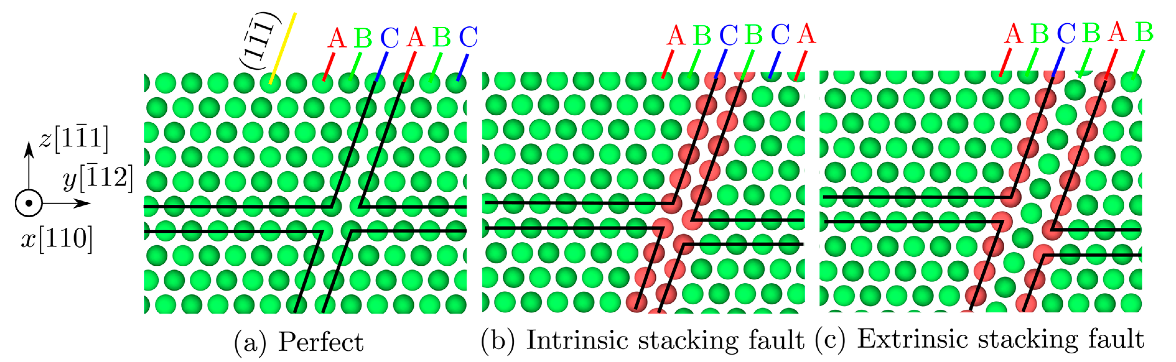
Figure 3.
(a) An illustration of the simulation cell for interactions between a screw dislocation and an SF. An ISF is described using Model-AT and Model-0, as shown in (b,c), respectively. An ESF is described using Model-AT, Model-1, and Model-2, as shown in (d–f), respectively. The red and gray circles are nodes and atoms, respectively. The gray shades are rhombohedral elements. The green line is the dislocation migration pathway if the dislocation is transmitted across the SF.

Figure 4.
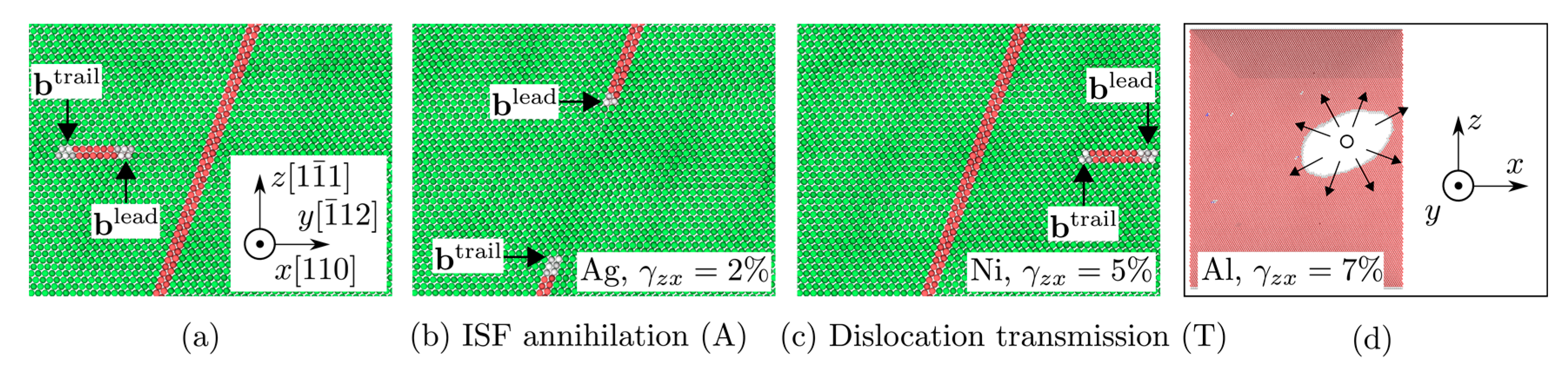
Atomic configurations of (a) a screw dislocation approaching the ISF (reaction 1) and range of observed reactions that includes (b) annihilation of the ISF (A, reaction 3) and (c) transmission of the screw dislocation across the ISF (T, reaction 1). In (a–c), the Burgers vectors of the leading (lead) and trailing (trail) partial dislocations are given in the corresponding reactions. The applied shear strain γzx is zero in (a). (d) Shear-induced annihilation of the ISF in the absence of an incoming lattice dislocation; specifically, the restoration of the perfect lattice arrangement is initiated within the ISF (open circle) and spreads out across the ISF (arrows). Atoms are colored in the same way as in Figure 2a–c, which possess the same orientation (shown in (a)), while (d) shows a different view with all FCC atoms deleted.
Figure 4.
Atomic configurations of (a) a screw dislocation approaching the ISF (reaction 1) and range of observed reactions that includes (b) annihilation of the ISF (A, reaction 3) and (c) transmission of the screw dislocation across the ISF (T, reaction 1). In (a–c), the Burgers vectors of the leading (lead) and trailing (trail) partial dislocations are given in the corresponding reactions. The applied shear strain γzx is zero in (a). (d) Shear-induced annihilation of the ISF in the absence of an incoming lattice dislocation; specifically, the restoration of the perfect lattice arrangement is initiated within the ISF (open circle) and spreads out across the ISF (arrows). Atoms are colored in the same way as in Figure 2a–c, which possess the same orientation (shown in (a)), while (d) shows a different view with all FCC atoms deleted.

Figure 5.
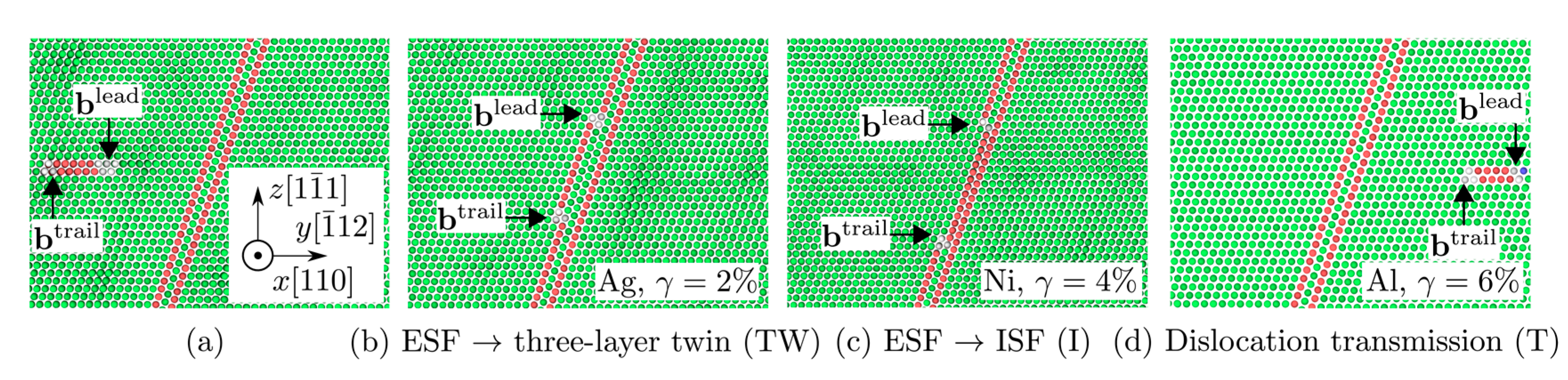
Atomic configurations of (a) a screw dislocation approaching the ESF (reaction 1) and range of observed reactions that includes (b) transformation of the ESF into a three-layer twin (TW, reaction 4), (c) transformation of the ESF into an ISF (I, reaction 3), and (d) transmission of the screw dislocation across the ESF (T, reaction 1). The applied shear strain γzx is zero in (a). The Burgers vectors of the leading (lead) and trailing (trail) partial dislocations are given in the corresponding reactions. Atoms are colored in the same way as in Figure 2, and the view is illustrated in (a).
Figure 5.
Atomic configurations of (a) a screw dislocation approaching the ESF (reaction 1) and range of observed reactions that includes (b) transformation of the ESF into a three-layer twin (TW, reaction 4), (c) transformation of the ESF into an ISF (I, reaction 3), and (d) transmission of the screw dislocation across the ESF (T, reaction 1). The applied shear strain γzx is zero in (a). The Burgers vectors of the leading (lead) and trailing (trail) partial dislocations are given in the corresponding reactions. Atoms are colored in the same way as in Figure 2, and the view is illustrated in (a).

Table 1.
Screw dislocation/ISF interaction modes for a variety of materials (Ni, Al, and Ag), models (Model-AT and Model-0), and applied shear strains γzx (2%~6%). Two modes are observed: annihilation of the ISF (A) and transmission of the screw dislocation across the ISF (T), a common sequence for screw dislocation/ISF interactions with an increasing applied shear strain.
| Material | Model | γzx = 2% | γzx = 3% | γzx = 4% | γzx = 5% | γzx = 6% |
|---|---|---|---|---|---|---|
| Ni | Model-AT | A | A | A | T | T |
| Ni | Model-0 | A | A | A | T | T |
| Al | Model-AT | A | A | A | A | A |
| Al | Model-0 | A | A | A | A | A |
| Ag | Model-AT | A | T | T | T | T |
| Ag | Model-0 | A | T | T | T | T |
Table 2.
Screw dislocation/ESF interaction modes for a variety of materials (Ni, Al, and Ag), models (Model-AT, Model-1, Model-2), and applied shear strains γzx (2%~6%). Three modes are observed: transformation of an ESF into a three-layer twin (TW), transformation of an ESF into an ISF (I), and transmission of the screw dislocation across the ESF (T), a common sequence for screw dislocation/ESF interactions with an increasing applied shear strain.
| Material | Model | γzx = 2% | γzx = 3% | γzx = 4% | γzx = 5% | γzx = 6% |
|---|---|---|---|---|---|---|
| Ni | Model-AT | TW | I | I | T | T |
| Ni | Model-1 | I | I | I | T | T |
| Ni | Model-2 | TW | I | I | T | T |
| Al | Model-AT | TW | TW | TW | TW | T |
| Al | Model-1 | I | I | I | I | T |
| Al | Model-2 | TW | TW | TW | TW | T |
| Ag | Model-AT | TW | I | T | T | T |
| Ag | Model-1 | I | I | T | T | T |
| Ag | Model-2 | TW | I | T | T | T |
Table 3.
The runtime t (s) and the coarse-graining efficiency ψ for different models. ψ is calculated with respect to the runtime of the fully-resolved atomistic model (Full-AT). Twenty-four cores are used in each run of dislocation/ISF interactions in Ni subject to an applied shear strain of 3%.
Table 3.
The runtime t (s) and the coarse-graining efficiency ψ for different models. ψ is calculated with respect to the runtime of the fully-resolved atomistic model (Full-AT). Twenty-four cores are used in each run of dislocation/ISF interactions in Ni subject to an applied shear strain of 3%.
| Full-AT | Model-AT | Model-0 | Model-1 | Model-2 | |
|---|---|---|---|---|---|
| t (s) | 7165 | 1043 | 846 | 876 | 924 |
| ψ | 1 | 6.87 | 8.47 | 8.18 | 7.75 |
© 2017 by the authors. Licensee MDPI, Basel, Switzerland. This article is an open access article distributed under the terms and conditions of the Creative Commons Attribution (CC BY) license (http://creativecommons.org/licenses/by/4.0/).
Share and Cite
MDPI and ACS Style
Xu, S.; Xiong, L.; Chen, Y.; McDowell, D.L. Validation of the Concurrent Atomistic-Continuum Method on Screw Dislocation/Stacking Fault Interactions. Crystals 2017, 7, 120. https://doi.org/10.3390/cryst7050120
AMA Style
Xu S, Xiong L, Chen Y, McDowell DL. Validation of the Concurrent Atomistic-Continuum Method on Screw Dislocation/Stacking Fault Interactions. Crystals. 2017; 7(5):120. https://doi.org/10.3390/cryst7050120
Chicago/Turabian StyleXu, Shuozhi, Liming Xiong, Youping Chen, and David L. McDowell. 2017. "Validation of the Concurrent Atomistic-Continuum Method on Screw Dislocation/Stacking Fault Interactions" Crystals 7, no. 5: 120. https://doi.org/10.3390/cryst7050120
Note that from the first issue of 2016, this journal uses article numbers instead of page numbers. See further details here.