Abstract
The effect of abrasive shape on the three-body abrasion behaviors of monocrystalline silicon was investigated via molecular dynamics. The axial ratio of abrasive particle varied from 1.00 to 0.40 to mimic abrasive shape. It has been observed that the particle’s movement became sliding instead of rolling when the axial ratio was smaller than a critical value 0.46. In the abrasion process, the friction force and normal force showed an approximately sinusoid-like fluctuation for the rolling ellipsoidal particles, while the front cutting of particle caused that friction force increased and became larger than normal force for sliding particles. The phase transformation process was tracked under different particle’ movement patterns. The Si-II and Bct5 phase producing in loading process can partially transform to Si-III/Si-XII phase, and backtrack to original crystal silicon under pressure release, which also occurred in the abrasion process. The secondary phase transformation showed difference for particles’ rolling and sliding movements after three-body abrasion. The rolling of particle induced the periodical and inhomogeneous deformation of substrates, while the sliding benefited producing high-quality surface in chemical mechanical polishing (CMP) process. This study aimed to construct a more precise model to understand the wear mechanism benefits evaluating the micro-electro-mechanical systems (MEMS) wear and CMP process of crystal materials.
1. Introduction
Monocrystalline silicon (Si), as the key component of micro-electro-mechanical systems (MEMS), has been broadly investigated, recently [1,2,3]. It is worthy to note that the mechanical characteristics of silicon, especially the relatively poor friction and wear behaviors, severely limit the working stability of MEMS [4,5]. The research indicated that in the wear process, the adhesive wear of silicon materials transformed to the abrasive wear because of the accumulation of wear debris between components, which can be accurately described by the three-body abrasion. This process finally leads to the failure of MEMS devices [6,7]. However, the interaction, controlling the worn behaviors and mechanisms, between abrasive particle and the silicon substrates, is still indistinct.
On the other hand, chemical mechanical polishing (CMP) technique is an important intermediate manufacture technology to improve the surface quality [8]. In the CMP process, the slurry is usually comprised of a liquid solution containing specific chemicals and abrasive particles that play a key role in the material polishing. The abrasive particles are usually driven over the wafer surface by the relative motion between the wafer and the pad. Microscopic analysis of polished surfaces manifested that the mechanical effects of slurry occurred as the repeated sliding, rolling, or indentation of abrasive particles against the wafer surface [8,9,10]. Clearly, it is of substantial importance to deeply understand the abrasive wear behaviors accompanying with possible phase transformation for achieving ideal surface planarization in CMP process.
There have been various methods, such as in situ experiment, X-ray diffraction, Raman spectroscopy, and transmission electron microscopy (TEM), to explore the abrasive wear behavior, especially for the three-body abrasion of silicon materials [4,11,12,13,14,15]. Oliver [16] evaluated various combinations of component factors, such as the size of abrasive particles, type of workpiece, and additives, based on CMP results. Su [17] studied the floating polishing process and manifested that the sliding action on particle surface contributed a driving force to produce the material removal, but the rolling action decreased machining efficiency. It was concluded that a slender particle shape is beneficial to strengthen the material removal of the CMP process. All of those wear models or experiments were proposed from a pure cutting removal mechanism of spherical particles. Actually, the abrasive particles in wear systems are not regular spheres for either wear of MEMS or CMP process. Anantheshwara et al. [11] stressed the dependence of particle movement pattern, including sliding, rolling, and their combinations occurring, on the particle geometry in nanoscale three-body abrasion. Fang et al. [18] assumed an ellipsoidal particle as the first approximation to model real particle contours in three-body abrasion. In addition, much effort has been paid for the abrasion properties of monocrystalline silicon at nanoscale by the molecular dynamics (MD) simulation [19,20,21,22,23]. For instance, Sun et al. [24,25] simulated three-body and two-body abrasive wear of monocrystalline silicon with sphere particle in geometry in the nanoscale. They became conscious of the rolling movement of sphere particle and found that the sliding of particle can prevent the large elastic recovery. Whilst, the friction and wear behaviors of diamond nanoparticles between other solid surfaces were studied via the MD method [26,27,28]. Eder et al. observed a linear dependence of the contact area on the applied load in accordance with Greenwood-Williamson contact mechanics for the cubic abrasive particles on atomically rough iron surface [27]. Ewen et al. stressed that the spherical carbon nanodiamonds show good wear and friction reduction at high coverage and low pressure [28]. Clearly, different geometries of abrasive particles could change the movement patterns of particles and thereby result in different wear behavior under various wear conditions.
Further, the complicated phase transformation and the ambiguous plastic deformation of monocrystalline silicon are avoided in experiments and theory models due to their complexity. The phase transformation of monocrystalline silicon at a relatively small load and the emergence of nanometer twins at a large load were confirmed [19,20]. The simulations on the mechanical properties and deformation mechanism of silicon indicated the appearance of the metastable phases, Si-II, Si-XII, and amorphous phase during nanoindentation process. Whilst, several simulated results showed that the Si-I transformed into two types of body-centered-tetragonal phase, i.e., β-Si and Bct5 with fivefold coordination [4,22,23]. The abrasive wear of monocrystalline silicon showed a new phase transformation route, i.e., an initial diamond cubic silicon turned into high density amorphous phase beneath the moving particle and, then transformed into low density metastable amorphous phase in both two-body and three-body abrasion [24,25]. Consequently, phase transformation of monocrystalline silicon is still a research focus due to its complexity and variability, especially in three-body abrasion process, although most of the simulations simplified and even neglected the effect of abrasive particle on the abrasion behavior.
Based on the current status of abrasive wear research, it is necessary to illustrate the role of abrasive geometry contour in the three-body abrasion of monocrystalline silicon. Therefore, the effects of axial ratio of particle on the movement pattern of particle, the interaction between particle and substrates, and the phase transformation of silicon were studied using MD simulation. The ellipsoidal particle was assumed to be an approximation of real abrasive particle and its axial ratio varied from 1.00, i.e., a complete sphere, to 0.40, at which the particle is a reasonable oblate spheroid. The damage degree of monocrystalline silicon surface was evaluated qualitatively by discussing the phase transformation results and elastic recovery.
2. Simulation Model and Methodology
MD simulations were performed with LAMMPS code [29]. Figure 1. shows the sandwich model of three-body abrasion. The two silicon substrates consisted of 292,800 atoms with dimensions of 43.40 × 8.10 × 16.30 nm along x-[100], y-[010] and z-[001] directions, and were composed of boundary atom, thermostat atom, and Newtonian atom. The boundary layers on the bottom substrate were fixed to be rigid for providing structural stability. The thermostat layers were kept at a constant temperature of 300 K to mimic the heat dissipation in real wear process, while the remaining layers were freely moved according the Newton motion law.
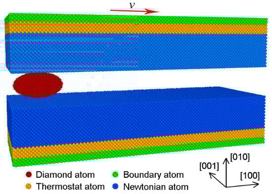
Figure 1.
The scheme of initial atomic model of three-body abrasion.
In the CMP process, ceria particles are usually used as abrasive particles with higher hardness when compared to monocrystalline silicon [30], which can be treated as rigid particles. In this work, the rigid diamond particles were modeled to facilitate the simulation process. To address the effect of abrasive axial ratio (γ) on the movement pattern of particle and deformed behavior of monocrystalline silicon, the geometry shape of particle varied from complete sphere to ellipsoid with different semi-axes a, b, and c. The corresponding parameters of particle are listed in Table 1. It can be found that the particle’ size or volume would be changed as the abrasive axial ratio was adjusted, simply by changing values of b, which means that the change of particle shape was accompanied by a variation of particle’ size.

Table 1.
Parameters of abrasive particle with different semi-axes a, b and c along x-, y-, and z-directions, respectively.
The interactive force between silicon atoms in the substrates were described by the Tersoff potential [31,32], and the interactive force between carbon atoms were ignored due to the rigid treatment. The interaction between silicon and diamond particle was depicted with Morse potential [24]:
where V(r) is a pair potential energy function, D = 0.435 eV is the cohesion energy, α = 4.6487 Å−1 is relevant to the elastic modulus, r and r0 = 1.9475 Å are the instantaneous and equilibrium distance between two atoms, respectively [21,33].
During simulating, periodic boundaries were applied in both x- and z-directions, but free boundary was set along y-direction. The equations of motion were integrated with the Velocity-Verlet algorithm with a time step 1 fs. At the beginning, a relaxation process of 100 ps was performed with NVT ensemble and Nose–Hoover thermostat [34,35]. Then, the upper specimen was moved along y-[010] direction to accomplish the constant loading of 80 nN, while the bottom specimen was kept motionless. After the second relaxation of 50 ps, the upper specimen moved horizontally along x-[100] direction on the (010) crystal plane at a constant sliding velocity 50 m/s. The sliding process of the upper specimen was lasted for 1000 ps, corresponding to the sliding distance of 50 nm. During the loading and sliding, all of the simulations were carried out at NVE ensemble with the Langevin thermostat to control the temperature of thermostat layer at 300 K.
3. Results and Discussion
3.1. Movement Pattern of Abrasive Particle
The movement pattern of abrasive particle is a very important factor in estimating the materials’ wear characteristics [18]. To measure the movement pattern of ellipsoidal particle, we expressed the atomic instantaneous configurations, as shown in Figure 2, and the semi-major axis was marked with a white dash line. From Figure 2a–d showing the change of particles’ axial ratio from 1.0 to 0.48, we can find that the position of the marked semi-major axis varied and the rotation angle between the semi-major axis and −x axis varied from 0° to 180° with simulation time. It can be concluded that the particle rolls if the axial ratio is larger than 0.48. When the axial ratio of particle was smaller than 0.48, the particle slid, as shown in Figure 2e,f. Resultantly, a particle with smaller axial ratio simulating the sharper particle shows a larger sliding tendency, which is much easier to plough the substrate surface in abrasion process. Furthermore, it is interesting that rolling occurred for the particle with the axial ratio 0.45 at the initial stage, as shown in Figure 2e, and then, the particle slid till the end of simulation process.
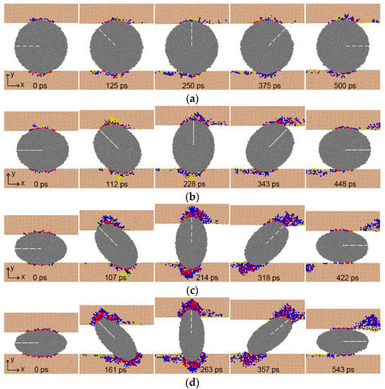
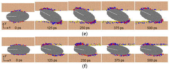
Figure 2.
Atomic instantaneous configurations with different axial ratio (a) 1.00; (b) 0.80; (c) 0.60; (d) 0.48; (e) 0.45; and (f) 0.40. Atoms were colored according to the coordination number: tan, perfect diamond (Si-I) atoms; yellow, Si-III/Si-XII atoms; blue, Bct5 atoms; red, Si-II atoms.
Figure 3 and Figure S1 (in Supplementary Material) show the displacement of upper specimen and the angular velocity of abrasive particle, respectively. For sphere particle, both the displacement along y-direction and angular velocity (around 0.6 × 10⁻² rad/ps) were constant. We can also find that the displacement-time curves for particles with the axial ratio 0.80, 0.60, and 0.48 showed sinusoidal curves and their amplitudes increased with the reducing axial ratio. From Figure 3b–d, the positive angular velocity illustrates that the ellipsoidal particle rolled as the axial ratio was larger than 0.48, as shown in Figure 2b–d. The angular velocity displaying an average fluctuation manifested the rolling movement of particle, namely, the increase in angular velocity demonstrates that the particle falls down from the upright posture to the lying in flat, and vice versa. Especially, the angular velocity of the particle with axial ratio 0.48 became very close to 0 around 400–500 ps and 900–1000 ps, meaning that the particle tended to slide over the short period of time. This indicates that the axial ratio 0.48 is close to a critical value causing the change of the particle movement pattern from rolling to sliding under the certain normal load (80 nN) and sliding velocity (50 m/s). When the axial ratio was less than 0.48, the displacement of upper specimen increased slightly and then kept constant (Figure S1), and in the meantime, the angular velocity of particle decreased from a nonzero value to zero (Figure 3e,f). This means that the beginning of particle sliding needs a critical tilt angle (about 22° and 12° for axial ratio 0.45 and 0.40, respectively), which provides the driving force of sliding.
Figure 3.
Angular velocity of abrasive center-of-mass vs. time at different abrasive axial ratio (a) 1.00; (b) 0.80; (c) 0.60; (d) 0.48; (e) 0.45; and (f) 0.40.
The prediction of the movement pattern of particle is very important to determine the worn morphology and understand the wear mechanism. Fang et al. have established the criterion of movement pattern of particle to quantify the correlation between theoretical and experimental studies [18,25,36,37,38,39], which was described by the following formulas and shown in Supplementary Material:
where is the coefficient of friction (COF) of particle, e and h is the distance between the central contact point of distributed forces on the particle surface and the geometric center of ellipsoidal particle along x and y direction, respectively.
The e/h was calculated from the modified equation [18], and the forces were assumed to be equally distributed at the contact zone (ASBC area in Figure S2 in Supplementary Material). Figure S3 shows the e/h curves and COF relative to the simulated time. The e/h was distinctly smaller for the rolling particle than that for the sliding particle, as well as the COF. The average value of COF and e/h as a function of the axial ratio was displayed in Figure 4. In this figure, both the e/h and COF increased with the decreasing axial ratio, but the e/h value exceeded μ when the axial ratio was smaller than a critical value 0.46. Consequently, relying on the criterion of movement pattern, there was a critical axial ratio (about 0.46) for ellipsoidal particle in three-body abrasion under the certain conditions. When the axial ratio reduced from a large value and then passed over the critical value, the abrasive particle would slide changing from rolling. It is noteworthy that the critical axial ratio maybe varies under different conditions with respect to key parameters, such as temperature, normal load, and sliding velocity [40,41].
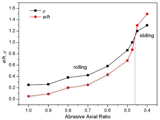
Figure 4.
Average friction coefficient (μ) and e/h value at different axial ratio of particles.
Furthermore, with the decrease of axial ratio, the friction coefficient increases obviously and even larger than 1.0 for the sliding particle, which is much larger than experimental results. As predicted by macroscale theory, the friction coefficient is comprised of the ploughing and adhesion components [42,43]. Actually, at the nanoscale, the adhesion friction occurring at the contact regions is very large and even larger than the ploughing friction, and also the contribution of chip or wear debris to friction force cannot be underestimated due to the accumulation of a large number of deformed atoms in front of particle [44]. Therefore, from the perspective of atomic scale, the large friction coefficient is reasonable. Clearly, the higher friction for particles’ sliding when compared to rolling at atomic scale matches the common results at the macroscale, which, however, seems to be challenged at some specific microscale. Coffey and Krim utilized quartz crystal microbalance to measure friction levels for molecularly thin methanol films sliding along C60 substrates in rapid and repressed rotational states, and they observed an increased friction for the case of rapid rotation C60 [45]. Thereafter, Braun and Tosatti indicated that rolling spherical lubricant molecules can indeed provide better tribological parameters than sliding atomic lubricants, however, it is as large as in macroscopic friction only for a low concentration of lubricant molecules, and for special systems and friction conditions [46]. By comparing these results, one needs to carefully check the ingredients of the macroscale and nanoscale systems before making the claim whether the rolling benefits the friction reduction.
It is necessary to analyze the friction force and normal force, as driving and resistant forces, to predict the particles’ movement pattern. As shown in Figure 5a, for the spherical particle that is rolled, both the friction force and normal force kept almost unchanged during the abrasion process. For the ellipsoidal particles which rolled, the friction force and normal force fluctuated in sinusoid-like curve approximately at the first half cycle. The curves, however, became much more complicated at the second half cycle. When the ellipsoidal particle fell down from upright posture the normal load decreased faster than the friction force. Sometimes normal load changed to negative value for axial ratio from 0.80 to 0.48 due to interatomic attractive force. Friction force was always the driving force and normal force resistant force whether the particle was in the rising or falling stage during rolling. For the sliding particles, as the front of ellipsoidal particle cut the specimen surface, a large number of Si atoms accumulated ahead of particle, which increased friction force substantially (see Figure 2e,f). Hence, the friction force increased significantly and even became larger than the normal force in Figure 5e,f. Similar results have already been reported by others [47].
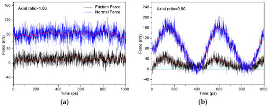
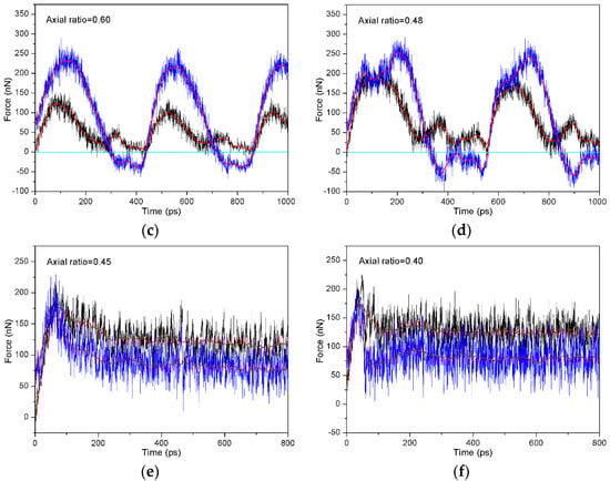
Figure 5.
Friction force and normal force vs. time at different axial ratio (a) 1.00; (b) 0.80; (c) 0.60; (d) 0.48; (e) 0.45; and (f) 0.40. Black line is friction force, blue line is normal force and red line is the fitness.
By analyzing the abrasion process, we considered that there exists a critical angle. Once passing over the critical angle, the particle would begin to roll, corresponding to the falling down stage, as presented in Figure 2d. Consequently, in a short period of time, the friction force turned to zero, while the repulsive normal force turned to attractive force, as shown in Figure 5b–d. Those indicate that the particle sharpness reflected by axial ratio can induce the change of interactive force, and thereby influenced the movement pattern.
3.2. Phase Transformation of Monocrystalline Silicon
The friction and normal forces vary with the change of abrasive shape, as shown in Figure 5, which controls the movement pattern of abrasive particle and then influences the deformation of monocrystalline silicon. Figure 2 shows the different phase transformation behaviors for monocrystalline silicon at different moving stages of the ellipsoidal particle. For instance, as the ellipsoidal particle is at the upright position, the phase transformation is larger in quantity than that in lying posture. Contrarily, the particles with spherical shape or sliding movement cause much less phase transformation in quantity when compared with the rolling movement.
To further obtain the phase distributions of monocrystalline silicon, the atomic configurations were extracted in Figure 6 and Figure 7 for the particle with axial ratio 0.80 and 0.40, respectively. Different regions on silicon surface were labeled to identify the phase features. In the initial loading region (T1–T3 in Figure 6 and Figure 7b–d), the Si-II phase with sixfold coordination and the Bct5 phase with fivefold coordination appeared interactively, some surface atoms (yellow) also appeared and separated the Si-II and Bct5 atoms, and the Si-III/Si-XII phase with fourfold coordination transformed from the initial diamond cubic structure appeared in a deeper position. This phase distribution is somewhat different from the previous observation, in which the Si-II phase surrounded by the Bct5 phase occurred at the center and side of the transformational region and a mixed phase of Si-I and Si-III/Si-XII was found beneath the particle [4,24,25]. That is mainly attributed to the small external load of 80 nN resulting in a very shallow indentation in this simulation process. With the particle moving away from the loading region, almost all of the phase-transformation atoms disappeared and transformed into the original Si-I atoms again, as shown in (e–g) of Figure 6 and Figure 7. The phase transformation after the particle departing was also confirmed by the atomic number difference in Figure 8. After 20 ps the particle moving off from T3 region, the number differences of phase-transformation Si-II and Bct5 atoms were less than zero, whilst that of Si-III/Si-XII was above zero. This indicates that a fraction of Si-II and Bct5 atoms transformed into Si-III/Si-XII atoms, rather than Si-I atoms.
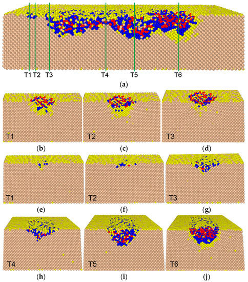
Figure 6.
(a), whole cross-section view of phase distribution induced by rolling of particle with axial ratio 0.80; (b–d), cross-section view of initial loading region labelled by T1–T3 before the top substrate moving and (e–g) after the top substrate moving; (h–j), cross-section view of particle lying region (T4), particle upright region (T5) and particle occupying region (T6). Atomic color is similar to that coding in Figure 2.
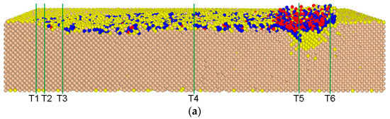
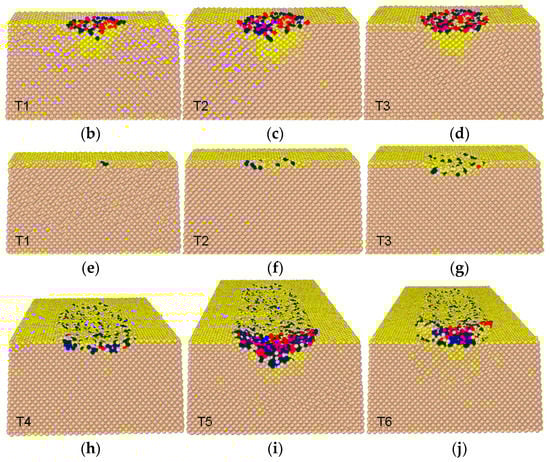
Figure 7.
(a), whole cross-section view of phase distribution induced by rolling of particle with axial ratio 0.40; (b–d), cross-section view of initial loading region labelled by T1–T3 before the top substrate moving and (e–g) after the top substrate moving; (h–j), cross-section view of particle sliding region (T4) and particle occupying region (T5 and T6). Atomic color is similar to that coding in Figure 2.
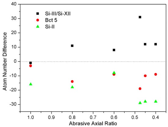
Figure 8.
Number difference of the transformational atoms induced by loading to the remaining atoms at the instant of 20 ps from the particle starting to move off.
For the particle rolling process, the specimen deformation showed a clear difference at different movement stages and exhibited a periodical feature, for instance, the depth of deformed region and the number of deformed atoms for the ellipsoidal particle at upright position (see Figure 6a,i) were larger than that at lying posture (Figure 6a,h). However, for the particle sliding process, the deformation of specimens was nearly homogeneous in the whole scratched region in Figure 7a,h. The particle with sliding movement pattern could scratch the substrate surface, and then lead to more atom accumulation ahead of particle, but less deformation within substrate, when compared with rolling movement. Consequently, we can find in Figure 6j and Figure 7i,j that the phase-transformation atoms induced by rolling particle were more than that by sliding particle. Figure 6a,h–j show after three-body abrasion, only a part of Bct5 atoms and many Si-II atoms transformed into Si-I or Si-III/Si-XII atoms, whilst the other Si-II and Bct5 atoms still remained. Whereas, Figure 7a,h–j show that the transformation from Si-II and Bct5 phase to Si-I phase increased, whilst the remained Si-II and Bct5 atoms were restricted only within several layers in the scratched region, and almost all of Si-III/Si-XII atoms generating from either Si-I or Si-II and Bct5 atoms disappeared because of the pressure releasing. The similar phase transformation phenomena were also observed in two-body abrasion [24,25].
To quantitatively reveal the effect of abrasive shape accompaning with change of particle’ size on the scratched region, we made a statistics of the remaining transformation atom in a range of 25 nm (at least including a whole rolling period) in scratched region at the end of the three-body abrasion, as shown in Figure 9. It can be found that the remaining Bct5 atoms increased dramatically, while the Si-II and Si-III/Si-XII atoms showed a slightly increase with the decrease of the axial ratio for rolling particles. However, the decrease of the axial ratio caused a modest reduction of the remaining transformation atoms for particle’s sliding process. The statistic data were in good agreement with results in Figure 6 and Figure 7. All of those results reveal that particle’s sliding movement induces more homogenous surface structure than the rolling movement. The geometry of particle with different axial ratio has a significant influence on the plastic deformation of monocrystalline silicon.
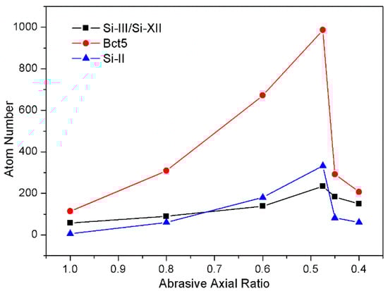
Figure 9.
Atom number of the remaining transformation atoms in the scratched region.
4. Damage Evaluation of Monocrystalline Silicon
It is important to evaluate the damage degree of monocrystalline silicon in the three-body abrasion process. Generally, the wear mechanism of materials comprises ploughing and cutting at macro scale [24]. However, the wear or deformation of crystal silicon at nanoscale becomes complicated with effect of abrasive particle shape, as shown in Figure 6, Figure 7 and Figure 8. From the abrasion configurations, as shown in Figure 2, it can be seen that the deformation behaviors of silicon specimens varied at different moving stages of abrasive particle. As ellipsoidal particle was at the upright position the phase transformation was larger in quantity than that in the lying posture, and the phase transformation that was caused by spherical particle or sliding ellipsoidal particles was much less when compared with rolling ellipsoidal particles.
In Figure 6 and Figure 8, we illustrated the complicated phase transformation, which induced the surface damage of monocrystalline silicon and was affected by the particle shape. For the particles’ rolling, the total number of phase-transformation atoms in the abrasion process and the number of remaining transformation atoms, in a range of 25 nm in the scratched region, increased with the decrease of the axial ratio, as shown in Figure 10. Meanwhile, Figure 6 shows that the deformation of silicon specimens exhibited an obvious periodicity, i.e., the number of transformational atoms and the depth of deformed region for particle with upright posture were larger than that with lying flat state. Those indicate that with the increase in the particle sharpness (i.e., smaller axial ratio), the rolling movement prominently caused the deterioration of surface quality. Whereas, the effects of the axial ratio on the number of transformational atoms (Figure 10) and the depth of deformed region were smaller for particles’ sliding movement, and the damage degree of specimen surface was nearly homogeneous in the whole scratched region (Figure 7). Clearly, the rolling process of ellipsoidal particle caused larger surface and subsurface damage.
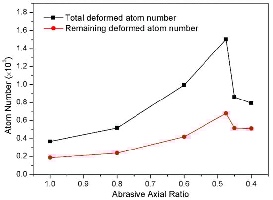
Figure 10.
Atom number of the total transformational atoms during the moving process of particles and the remaining transformational atoms in the scratched region.
On the other hand, the elastic recovery was an important factor to influence the abrasion behavior and damage degree of silicon material. We analyzed the evolution of the deformed region for both rolling and sliding movement by tracing atomic positions. It can be found that rolling ellipsoidal particle caused larger substrates deformation than the sliding particle. Therefore, the sliding movement of ellipsoidal particle in three-body abrasion benefits, producing high-quality surface of monocrystalline silicon wafer.
5. Conclusions
The MD simulation was implemented to investigate the influence of abrasive particle shape on the three-body abrasion process of monocrystalline silicon. The varying axial ratio reflecting the sharpness of ellipsoidal particle, accompanied by change of particle’ size, was used to mimic a relatively real abrasive particle. The results show the particle’ rolling movement pattern as the axial ratio decreased from 1.0 (complete sphere) to 0.48, with constant driving of the upper specimen. With the axial ratio less than 0.48, the movement of ellipsoidal particle transformed from rolling to sliding. Based on the criterion of the movement pattern, the movement pattern of particle can be predicted by comparing the value of e/h and coefficient of friction. The analysis of friction and normal forces indicates that the both two forces fluctuated in sinusoid-like curve approximately for the rolling ellipsoidal particles. As the ellipsoidal particle rolled away from the upright state, the friction force turned to zero and the repulsive normal force turned to attractive force. Due to the front cutting of sliding particle, the friction force increased significantly and became larger than the normal force. Then, the phase transformation process of monocrystalline silicon was tracked. The most of Si-II and Bct5 phase, generated in the initial loading process, transformed into original Si-I phase, but a part of them transformed into Si-III/Si-XII phase at the early stage of pressure release. During the moving process, the substrate deformation showed a periodical and inhomogeneous feature for particle’s rolling movement, but a nearly homogeneous feature for particle’s sliding. After three-body abrasion, there were a fraction of Bct5 atoms and lots of Si-II atoms transforming into Si-I or Si-III/Si-XII atoms, whilst the other Si-II and Bct5 atoms still remained for the rolling movement. For the sliding movement, there were only several layers of Si-II and Bct5 atoms remaining in the scratched region but the most of them transformed to Si-I atoms. Finally, the damage degree of monocrystalline silicon was evaluated qualitatively by discussing the phase transformation results and elastic recovery. The sliding movement of ellipsoidal particle was beneficial to produce high-quality surface than the rolling.
Furthermore, it is well known that in real CMP process, the polishing conditions are very complex, for instance the aqueous slurry consisting of abrasive particles in a mixture of several chemicals has an important effect on the polishing environment. The roughness of the particles also influences the polishing behaviors because the particles have facets or even sub-asperities in real life. Thus, it is necessary to take into account these factors in a more realistic MD scenario to reveal the complex process.
Supplementary Materials
The following are available online at www.mdpi.com/2073-4352/8/1/32/s1.
Acknowledgments
This work was supported by the National Natural Science Foundation of China [Grant No. 51375364, 51475359] and the Natural Science Foundation of Shaanxi Province of China [2014JM6219].
Author Contributions
Junqin Shi, Liang Fang and Kun Sun conceived and designed the simulation, and Junqin Shi wrote the paper; Xinqi Wei performed the simulation; Junqin Shi, Xinqi Wei and Juan Chen analyzed the data.
Conflicts of Interest
The authors declare no conflict of interest.
References
- Huang, H.; Yan, J.W. New insights into phase transformations in single crystal silicon by controlled cyclic nanoindentation. Scr. Mater. 2015, 102, 35–38. [Google Scholar] [CrossRef]
- Zhang, L.C.; Tang, C.Y. Friction and wear of diamond–silicon nano-systems: Effect of moisture and surface roughness. Wear 2013, 302, 929–936. [Google Scholar] [CrossRef]
- Zhang, L.; Zhao, H.W.; Yang, Y.H.; Huang, H.; Ma, Z.C.; Shao, M.K. Evaluation of repeated single-point diamond turning on the deformation behavior of monocrystalline silicon via molecular dynamic simulations. Appl. Phys. A 2014, 116, 141–150. [Google Scholar] [CrossRef]
- Kim, D.E.; Oh, S.I. Atomistic simulation of structural phase transformations in monocrystalline silicon induced by nanoindentation. Nanotechnology 2006, 17, 2259–2265. [Google Scholar] [CrossRef]
- Subhash, G.; Corwin, A.D.; de Boer, M.P. Evolution of Wear Characteristics and Frictional Behavior in MEMS devices. Tribol. Lett. 2014, 1, 177–189. [Google Scholar] [CrossRef]
- Alsem, D.H.; Dugger, M.T.; Stach, E.A.; Ritchie, R.O. Microscale friction and sliding wear of polycrystalline silicon thin structural films in ambient air. J. Microelectromech. S 2008, 17, 1144–1145. [Google Scholar] [CrossRef]
- Shen, S.; Meng, Y.; Zhang, W. Characteristics of the wear process of side-wall surfaces in bulk-fabricated Si-MEMS devices in nitrogen gas environment. Tribol. Lett. 2012, 47, 455–466. [Google Scholar] [CrossRef]
- Kasai, T.; Bhushan, B. Physics and tribology of chemical mechnical planarization. J. Phys. Condens. Matter 2008, 20, 225011. [Google Scholar] [CrossRef]
- Luo, J.F.; Dornfeld, D.A. Material removal mechanism in chemical mechanical polishing: Theory and modeling. IEEE Trans. Semicond. Manuf. 2001, 14, 112–133. [Google Scholar]
- Luo, J.F.; Dornfeld, D.A. Material removal regions in chemical mechanical planarization for submicron integrated circuit fabrication: Coupling effects of slurry chemicals, abrasive size distribution, and wafer-pad contact area. IEEE Trans. Semicond. Manuf. 2003, 16, 45–56. [Google Scholar]
- Anantheshwara, K.; Lockwood, A.J.; Mishra, R.K.; Inkson, B.J.; Bobji, M.S. Dynamical evolution of wear particles in nanocontacts. Tribol. Lett. 2012, 45, 229–235. [Google Scholar] [CrossRef]
- Gupta, M.C.; Ruoff, A.L. Static compression of silicon in the [100] and in the [111] directions. J. Appl. Phys. 1980, 51, 1072–1075. [Google Scholar] [CrossRef]
- Clarke, D.R.; Kroll, M.C.; Kirchner, P.D.; Cook, R.F. Amorphization and conductivity of silicon and germanium induced by indentation. Phys. Rev. Lett. 1988, 60, 2156–2159. [Google Scholar] [CrossRef] [PubMed]
- Mann, A.B.; Van, H.D.; Pethica, J.B.; Bowes, P.; Weihs, T.P. Contact resistance and phase transformations during nanoindentation of silicon. Philos. Mag. A 2002, 82, 1921–1929. [Google Scholar] [CrossRef]
- Bradby, J.E.; Williams, J.S.; Swain, M.V. In situ electrical characterization of phase transformations in Si during indentation. Phys. Rev. B 2003, 67, 085205. [Google Scholar] [CrossRef]
- Oliver, M.R. Chemical Mechanical Planarization of Semiconductor Materials; Springer: Heidelberg, Germany, 2004. [Google Scholar]
- Su, Y.T. Investigation of removal rate properties of a floating polishing process. J. Electrochem. Soc. 2000, 147, 2290–2296. [Google Scholar] [CrossRef]
- Fang, L.; Zhao, J.; Li, B.; Sun, K. Movement patterns of ellipsoidal particle in abrasive flow machining. J. Mater. Process. Technol. 2009, 209, 6048–6056. [Google Scholar] [CrossRef]
- Zhang, L.; Tanaka, H. Atomic scale deformation in silicon monocrystals induced by two-body and three-body contact sliding. Tribol. Int. 1998, 31, 425–433. [Google Scholar] [CrossRef]
- Mylvaganam, K.; Zhang, L.C. Nanotwinning in monocrystalline silicon upon nanoscratching. Scr. Mater. 2011, 65, 214–216. [Google Scholar] [CrossRef]
- Du, X.C.; Zhao, H.W.; Zhang, L.; Yang, Y.H.; Xu, H.L.; Fu, H.S.; Li, L.J. Molecular dynamics investigations of mechanical behaviours in monocrystalline silicon due to nanoindentation at cryogenic temperatures and room temperature. Sci. Rep. 2015, 5, 16275. [Google Scholar] [CrossRef] [PubMed]
- Eyben, P.; Clemente, F.; Vanstreels, K.; Pourtois, G.; Clarysse, T.; Duriau, E.; Hantschel, T. Analysis and modeling of the high vacuum scanning spreading resistance microscopy nanocontact on silicon. J. Vac. Sci. Technol. B 2010, 28, 401–406. [Google Scholar] [CrossRef]
- Kim, D.E.; Oh, S.I. Deformation pathway to high-pressure phases of silicon during nanoindentation. J. Appl. Phys. 2008, 104, 013502. [Google Scholar] [CrossRef]
- Sun, J.P.; Fang, L.; Han, J.; Han, Y.; Chen, H.W.; Sun, K. Abrasive wear of nanoscale single crystal silicon. Wear 2013, 307, 119–126. [Google Scholar] [CrossRef]
- Sun, J.P.; Fang, L.; Han, J.; Han, Y.; Chen, H.W.; Sun, K. Phase transformations of mono-crystal silicon induced by two-body and three-body abrasion in nanoscale. Comput. Mater. Sci. 2014, 82, 140–150. [Google Scholar] [CrossRef]
- Hu, C.Z.; Bai, M.L.; Lv, J.Z.; Kou, Z.H.; Li, X.J. Molecular dynamics simulation on the tribology properties of two hard nanoparticles (diamond and silicon dioxide) confined by two iron blocks. Tribol. Int. 2015, 90, 297–305. [Google Scholar] [CrossRef]
- Eder, S.J.; Feldbauer, G.; Bianchi, D.; Cihak-Bayr, U.; Betz, G.; Vernes, A. Applicability of macroscopic wear and friction laws on the atomic length scale. Phys. Rev. Lett. 2015, 115, 025502. [Google Scholar] [CrossRef] [PubMed]
- Ewen, J.P.; Gattinoni, C.; Thakkar, F.M.; Morgan, N.; Spikes, H.A.; Dini, D. Nonequilibrium molecular dynamics investigation of the reduction in friction and wear by carbon nanoparticles between iron surfaces. Tribol. Lett. 2016, 63, 38. [Google Scholar] [CrossRef]
- Plimpton, S. Fast parallel algorithms for short-range molecular dynamics. J. Comput. Phys. 1995, 117, 1–19. [Google Scholar] [CrossRef]
- Chen, Y.; Li, Z.N.; Miao, N.M. Polymethylmethacrylate (PMMA)/CeO2 hybrid particles for enhanced chemical mechanical polishing performance. Tribol. Int. 2015, 82, 211–217. [Google Scholar] [CrossRef]
- Tersoff, J. Modelling solid-state chemistry: Interatomic potentials for multicomponent system. Phys. Rev. B 1989, 39, 5566–5568. [Google Scholar] [CrossRef]
- Tersoff, J. New empirical model for the structural properties of silicon. Phys. Rev. Lett. 1986, 56, 632–635. [Google Scholar] [CrossRef] [PubMed]
- Zhao, H.; Shi, C.; Zhang, P.; Zhang, L.; Huang, H.; Yan, J. Research on the effects of machining-induced subsurface damages on mono-crystalline silicon via molecular dynamics simulation. Appl. Surf. Sci. 2012, 259, 66–71. [Google Scholar] [CrossRef]
- Nose, S. A unified formulation of the constant temperature molecular dynamics methods. J. Chem. Phys. 1984, 81, 511–519. [Google Scholar] [CrossRef]
- Hoover, W.G. Constant-pressure equations of motion. Phys. Rev. A 1986, 34, 2499–2500. [Google Scholar] [CrossRef]
- Fang, L.; Zhou, Q.D. A statistical model describing wear traces in three-body abrasion. Lubr. Sci. 1995, 2, 47–53. [Google Scholar] [CrossRef]
- Fang, L.; Kong, X.L.; Zhou, Q.D. A wear tester capable of monitoring and evaluating the movement pattern of abrasive particles in three-body abrasion. Wear 1992, 159, 115–120. [Google Scholar]
- Fang, L.; Kong, X.L.; Su, J.Y.; Zhou, Q.D. Movement patterns of abrasive particles in three-body abrasion. Wear 1993, 162, 782–789. [Google Scholar] [CrossRef]
- Fang, L.; Zhou, Q.D.; Rao, Q.C. An experimental simulation of cutting wear in three-body abrasion. Wear 1998, 218, 188–194. [Google Scholar] [CrossRef]
- Shi, J.Q.; Chen, J.; Wei, X.Q.; Fang, L.; Sun, K.; Sun, J.P.; Han, J. Influence of normal load on the three-body abrasion behaviour of monocrystalline silicon with ellipsoidal particle. RSC Adv. 2017, 7, 30929–30940. [Google Scholar] [CrossRef]
- Fang, L.; Sun, K.; Shi, J.Q.; Zhu, X.Z.; Zhang, Y.N.; Chen, J.; Sun, J.P.; Han, J. Movement patterns of ellipsoidal particles with different axial ratios in three-body abrasion of monocrystalline copper: A large scale molecular dynamics study. RSC Adv. 2017, 7, 26790–26800. [Google Scholar] [CrossRef]
- Bowden, F.P.; Tabor, D. The Friction and Lubrification of Solids; Clarendon Press: Oxford, UK, 1950–1954; Volume 1. [Google Scholar]
- Moore, D.F. Principles and Applications of Tribology; Pergamon Press Ltd.: Oxford, UK, 1975. [Google Scholar]
- Zhu, P.Z.; Hu, Y.Z.; Ma, T.B.; Wang, H. Molecular Dynamics Study on Friction Due to Ploughing and Adhesion in Nanometric Scratching Process. Tribol. Lett. 2011, 41, 41–46. [Google Scholar] [CrossRef]
- Coffey, T.; Krim, J. C60 Molecular Bearings and the Phenomenon of Nanomapping. PRL 2006, 96, 186104. [Google Scholar] [CrossRef] [PubMed]
- Braun, O.M.; Tosatti, E. Rack-and-pinion effects in molecular rolling friction. Philos. Mag. Lett. 2008, 88, 509–517. [Google Scholar] [CrossRef]
- Ren, J.Q.; Zhao, J.S.; Dong, Z.G.; Liu, P.K. Molecular dynamics study on the mechanism of AFM-based nanoscratching process with water-layer lubrication. Appl. Surf. Sci. 2015, 346, 84–98. [Google Scholar] [CrossRef]
© 2018 by the authors. Licensee MDPI, Basel, Switzerland. This article is an open access article distributed under the terms and conditions of the Creative Commons Attribution (CC BY) license (http://creativecommons.org/licenses/by/4.0/).